installation, connection, exchange - the geek...
TRANSCRIPT
Ro/Me/03/23 03.99.02 en
1 of 26
ROBOT
KR 350
Installation, Connection, Exchange

2 of 26
Ro/Me/03/23 03.99.02 en
e Copyright KUKA Roboter GmbHThis documentation or excerpts therefrommay not be reproduced or disclosed to third parties without the express permission of the publishers.Other functions not described in this documentation may be operable in the controller. The user has no claim to these functions, however, inthe case of a replacement or service work.We have checked the content of this documentation for conformity with the hardware and software described. Nevertheless, discrepanciescannot be precluded, for which reason we are not able to guarantee total conformity. The information in this documentation is checked on aregular basis, however, and necessary corrections will be incorporated in subsequent editions.Subject to technical alterations without an effect on the function.
PD Interleaf

3 of 26
Ro/Me/03/23 03.99.02 en
Contents
1 General 5. . . . . . . . . . . . . . . . . . . . . . . . . . . . . . . . . . . . . . . . . . . . . . . . . . . . . . . . .
2 Principal loads 7. . . . . . . . . . . . . . . . . . . . . . . . . . . . . . . . . . . . . . . . . . . . . . . . . . .
3 Mounting variants 8. . . . . . . . . . . . . . . . . . . . . . . . . . . . . . . . . . . . . . . . . . . . . . . .
3.1 Variant 1 (394.001--08.002) 9. . . . . . . . . . . . . . . . . . . . . . . . . . . . . . . . . . . . . . . . . . . . . . . . . . . . . .
3.2 Variant 2 (394.001--08.003) 11. . . . . . . . . . . . . . . . . . . . . . . . . . . . . . . . . . . . . . . . . . . . . . . . . . . . . .
4 Installing and connecting the robot 15. . . . . . . . . . . . . . . . . . . . . . . . . . . . . . .4.1 Floor--mounted robots 15. . . . . . . . . . . . . . . . . . . . . . . . . . . . . . . . . . . . . . . . . . . . . . . . . . . . . . . . . .
4.2 Ceiling--mounted robots 17. . . . . . . . . . . . . . . . . . . . . . . . . . . . . . . . . . . . . . . . . . . . . . . . . . . . . . . . .
5 Exchange 21. . . . . . . . . . . . . . . . . . . . . . . . . . . . . . . . . . . . . . . . . . . . . . . . . . . . . . .5.1 Exchanging floor--mounted robots 21. . . . . . . . . . . . . . . . . . . . . . . . . . . . . . . . . . . . . . . . . . . . . . . .
5.2 Exchanging ceiling--mounted robots 24. . . . . . . . . . . . . . . . . . . . . . . . . . . . . . . . . . . . . . . . . . . . . .

Installation, Connection, Exchange
4 of 26
Ro/Me/03/23 03.99.02 en
1 General
5 of 26
Ro/Me/03/23 03.99.02 en
Valid for KR 350/2KR 350 L280/2KR 350 L240/2
1 General
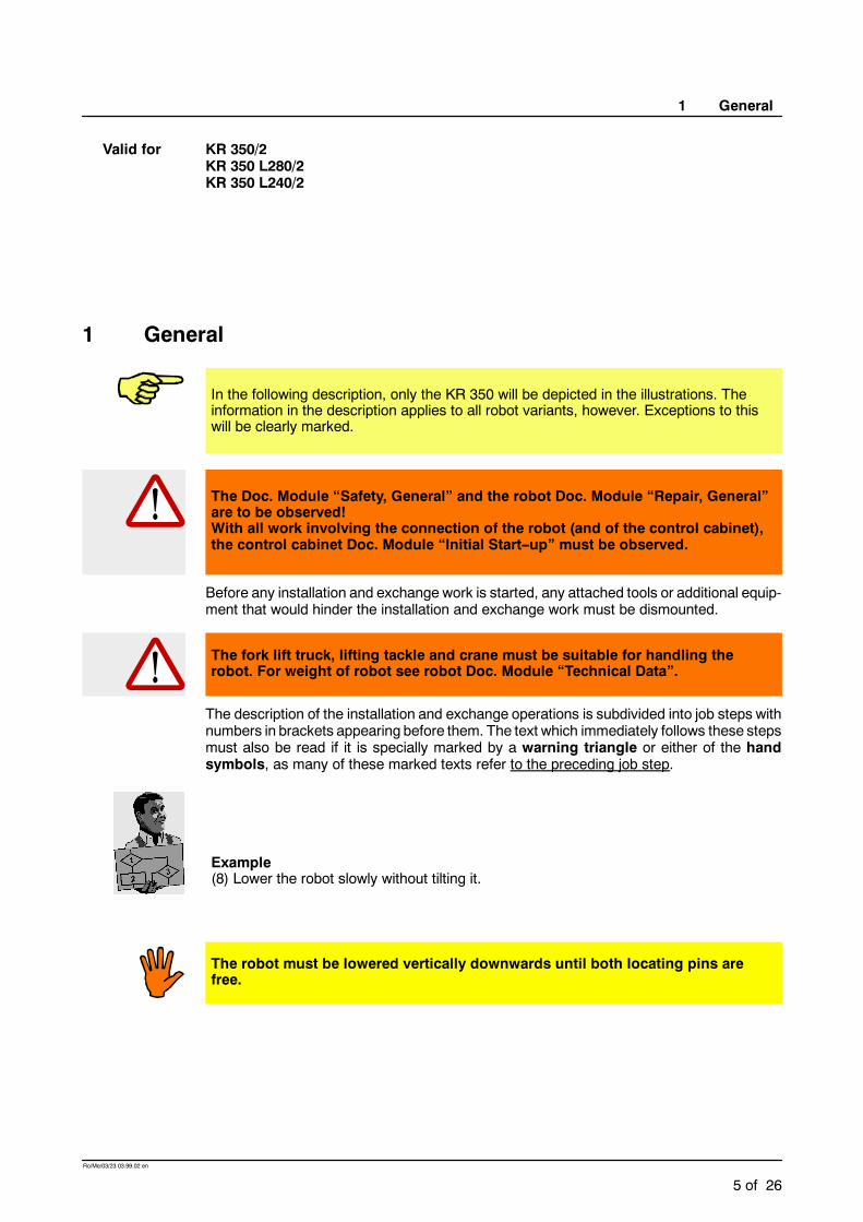
In the following description, only the KR 350 will be depicted in the illustrations. Theinformation in the description applies to all robot variants, however. Exceptions to thiswill be clearly marked.
The Doc. Module “Safety, General” and the robot Doc. Module “Repair, General”are to be observed!With all work involving the connection of the robot (and of the control cabinet),the control cabinet Doc. Module “Initial Start--up” must be observed.
Before any installation and exchange work is started, any attached tools or additional equip-ment that would hinder the installation and exchange work must be dismounted.
The fork lift truck, lifting tackle and crane must be suitable for handling therobot. For weight of robot see robot Doc. Module “Technical Data”.
The description of the installation and exchange operations is subdivided into job steps withnumbers in brackets appearing before them. The text which immediately follows these stepsmust also be read if it is specially marked by a warning triangle or either of the handsymbols, as many of these marked texts refer to the preceding job step.
Example(8) Lower the robot slowly without tilting it.
The robot must be lowered vertically downwards until both locating pins arefree.

Installation, Connection, Exchange
6 of 26
Ro/Me/03/23 03.99.02 en
Some of the specially marked texts refer exclusively to everything that follows -- until theinstruction is expressly revoked or the work is completed at the end of a section.
Example
Turn main switch on the robot control cabinet to “OFF” and secure it with a pad-lock to prevent unauthorized persons from switching it on again.

2 Principal loads
7 of 26
Ro/Me/03/23 03.99.02 en
2 Principal loads
Forces occur during operation of the robot which must be safely transmitted to the floor orceiling. The forces that have to be taken into account for floor-- and ceiling--mounted robotsare specified in Fig. 1. The drawings with their specifications can be used as a basis formoreextensive static investigations.
Fv = vertical force Fvmax = 28 000 NFh = horizontal force Fhmax = 15 000 NMk = tilting moment Mkmax = 50 000 NmMr = turning moment about axis 1 Mrmax = 26 500 Nm
Total mass = robot + total load for type
1940 kg + 500 kg KR 350/21956 kg + 430 kg KR 350 L280/21965 kg + 390 kg KR 350 L240/2
Fh
Fv
Mr
Mk
Fig. 1 Principal loads acting on floor (or ceiling) due to robot and total load

Installation, Connection, Exchange
8 of 26
Ro/Me/03/23 03.99.02 en
3 Mounting variants
Depending on the type, the robot can be installed on the floor or on the ceiling.
There are two mounting variations for installing the robot on the floor or on the ceiling:
G Variant 1 (394.001--08.002), see Section 3.1
G Variant 2 (394.001--08.003), see Section 3.2
If the robot is to be installed on the floor, being directly mounted on a concrete base, all perti-nent construction specifications must be observed concerning the grade of concrete (∫ B25according to DIN 1045) and the load--bearing capacity of thegroundwhenpreparing the con-crete foundation. It must beensured that the surfaceof the foundation is level and sufficientlysmooth. The anchors must be inserted with great care to ensure that the forces occurringduring the operation of the robot (Fig. 1) are transmitted safely to the ground.

3 Mounting variants (continued)
9 of 26
Ro/Me/03/23 03.99.02 en
3.1 Variant 1 (394.001--08.002)
Characteristic features:
-- For floor-- and ceiling--mounted robots
-- Robot installed on a steel structure prepared by the customer (or on a linear unitof series KL 1500)
-- Robot fastened by means of eight M24x100--8.8 ISO 4017 hexagon bolts.
Retighten M24x100--8.8 ISO 4017 hexagon bolts after 100 hours of operation.Tightening torque MA = 700 Nm.
Accessory: “frame mounting kit”
(1) Prepare mounting surfaces (Fig. 2/1) on steel structure in accordance with Fig. 2.M24
min. 115
min.350
220 M
8(2x)
1
4x
970
Fig. 2 Mounting surfaces for variant 1
(2) Drill eight holes for holding--down bolts (Fig. 3/3) and two holes for the locating pins(2, 5) as shown in Fig. 3.
The intended installation position of the robot, i.e. the correct orientation in relation tothe working envelope (Fig. 3/4), must be taken into account when drilling the holes.
(3) Insert locating pins (2, 5) and fasten each one with an M8x55 Allen screw (1) togetherwith lock washer.
The position of the locating pins in relation to the working envelope is important:Looking forwards (4) from the robot towards the working envelope -- the robot armpoints in this direction when A 1 is in its zero position --, then the sword pin (2) must beon the right and the round pin (5) on the left.

Installation, Connection, Exchange
10 of 26
Ro/Me/03/23 03.99.02 en
Section X - X
90 rotated
21 3min.25
10
max.6
ISO 4017 M24x100--8.8
1050
970¦ 0,1
960
960
220
220
min 115
min.350
410410
820
480
min115
1050
20H7M24
X
X
2
3
4
5
M8
MA=700 Nm
front
Fig. 3 Robot installation, variant 1
The steel foundation is now ready for the robot to be installed. The procedure for installingthe robot is described in Section 4.1 for floor--mounted robots, and in Section 4.2 for ceiling--mounted robots.

3 Mounting variants (continued)
11 of 26
Ro/Me/03/23 03.99.02 en
3.2 Variant 2 (394.001--08.003)
Characteristic features:
-- For floor--mounted robots only
-- Robot installed with four intermediate plates (Fig. 4/1) on the concrete foundation
-- Robot fastened to each intermediate plate with two M24x100 hexagon bolts (2)
-- Each intermediate plate fastened to concrete foundation with four safety anchors(3)
-- Easy removal and installationwith optimum repeatability of the installationposition
-- Considerable differences in level of the foundation can be bridged.
Accessory: “mounting base kit”
(1) Insert a set--up pin (Fig. 5/1) in two of the four intermediate plates (5) and fasten it withan M8x60 Allen screw (2) together with lock washer.
The set--up pins (1) are only used to install the plates correctly on the floor. They arethen replaced by locating pins (see step 14).
1
2
3
4
5
6
A1 center
1240
620
645
585
195
30±1
66
200
1240
970
960645585
19530±1
66
200
420
420
960
420 420
front
Fig. 4 Robot installation, variant 2

Installation, Connection, Exchange
12 of 26
Ro/Me/03/23 03.99.02 en
(2) Fasten each intermediate plate to the bottom of the robot by means of twoM24x100--8.8 hexagon bolts (Fig. 5/3) together with lock washers and centering rings(4) in accordance with Fig. 4.
(3) Lower robot onto the concrete foundation and align it correctly in relation to theworkingenvelope (Fig. 3/4).
To avoid distorting the robot base frame when fastening it to the intermediate plates,differences in level between the concrete foundation and the intermediate plates mustbe corrected using levelling compound (filling compound).
(4) Mark the position of the intermediate plates on the concrete foundation and determinethe magnitude of the differences in level.
(5) Lift off robot again together with intermediate plates.
1 2 3
45
Fig. 5 Intermediate plates for variant 2
(6) Apply levelling compound (Fig. 6/2) onto the marked areas on the concrete foundation(4).
“Knauf levelling compound”, for example, is a suitable compound for this purpose. It isapplied with a toothed spatula (tooth height > 2 x difference in level (5)).
The area (3) under each hexagon bolt (1) must be kept free from levelling com-pound or it must be cleared after the compound has been applied.

3 Mounting variants (continued)
13 of 26
Ro/Me/03/23 03.99.02 en
1 2
345
Fig. 6 Levelling compound
(7) Set down the robot in the still plastic levelling compound and adjust its position slightlyif necessary.
The robot can be levelled by turning an M20x40 hexagon bolt (Fig. 4/4) on eachintermediate plate.
(8) Allow the levelling compound to set for about three hours.
(9) Drill four anchor holes (Fig. 7/8) for each intermediate plate; minimumdepth in concrete160 mm.
The holes in the concrete foundation must be drilled through the holes (5) in theplates (6).
1
8
23 4
5
6
7
160
ø30
250
Fig. 7 Anchor boreholes for variant 2
(10) Insert anchors (7).

Installation, Connection, Exchange
14 of 26
Ro/Me/03/23 03.99.02 en
(11) Screw on hexagon nuts (4) together with lock washers and tighten hexagon nuts withtorque wrench in diagonally opposite sequence, increasing the tightening torque to thespecified value in several stages (MA = 300 Nm).
(12) Unscrew and remove all hexagon bolts (3) together with lock washers.
(13) Carefully lift robot vertically and remove centering rings that are then loose.
(14) Remove Allen screws (2) and replace both set--up pins (1) with locating pins.
The position of the locating pins in relation to the working envelope is important:Looking forwards from the robot towards the working envelope -- the robot arm points inthis direction when A 1 is in its zero position (Fig. 4) --, then the sword pin (5) must beon the right and the round pin (6) on the left.
Any levelling compound that has penetrated into the bottom of the holes mustbe removed from the eight tapped holes in the intermediate plates in order thatthe robot holding--down bolts can be screwed in completely.
(15) Set robot down onto intermediate plates (Fig. 7/6) and fasten it by means of eightM24x100 hexagon bolts (3) together with lock washers.
(16) Tighten hexagon screws (3) with torque wrench in diagonally opposite sequence,increasing the tightening torque to the specified value in several stages (MA = 700Nm).
(17) Retighten hexagon nuts (4) of the anchors after 24 hours with a tightening torque of300 Nm.
The levelling compound setting time of 24 hours must be strictly observed.
Retighten hexagon bolts (3) and hexagon nuts (4) after 100 hours of operation.
The robot is now ready to be installed in accordance with Section 4.1.

4 Installing and connecting the robot
15 of 26
Ro/Me/03/23 03.99.02 en
4 Installing and connecting the robot
4.1 Floor--mounted robots
Section 1 of this Doc. Module is to be observed.
This description applies to robots with mounting variant 1 (Section 3.1) and 2 (Section 3.2).If the robot is to be installed on the floor in an inclined position of more than 10˚, KUKAmustbe consulted beforehand.
The procedure for installing the robot (whether for the first time or as an exchange) is asfollows:
(1) Check that both locating pins (Fig. 8/2) and their fastening screws (1) are undamagedand fitted securely.
Damaged locating pins must be replaced by new ones.
21
Fig. 8 Locating pins
The robot must be in the transport position (Fig. 9)*.
A 1 A 2 A 3 A 4 A 5 A 6
0˚ - -40˚ +60˚ 0˚ +90˚ any
* Angle specificationsare referred to themechanical zero ofthe axis concerned.
I
h
l h
KR 350/2 1690 2420KR 350 L280/2 1780 2420KR 350 L240/2 1960 2420
Fig. 9 Transport position for floor--mounted robots
Installation, Connection, Exchange
16 of 26
Ro/Me/03/23 03.99.02 en
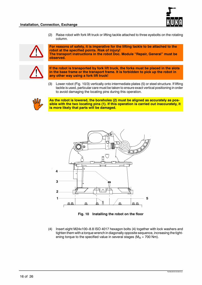
(2) Raise robot with fork lift truck or lifting tackle attached to three eyebolts on the rotatingcolumn.
For reasons of safety, it is imperative for the lifting tackle to be attached to therobot at the specified points. Risk of injury!The transport instructions in the robot Doc. Module “Repair, General” must beobserved.
If the robot is transported by fork lift truck, the forks must be placed in the slotsin the base frame or the transport frame. It is forbidden to pick up the robot inany other way using a fork lift truck!
(3) Lower robot (Fig. 10/3) vertically onto intermediate plates (5) or steel structure. If liftingtackle is used, particular caremust be taken to ensure exact vertical positioning in orderto avoid damaging the locating pins during this operation.
As the robot is lowered, the boreholes (2) must be aligned as accurately as pos-sible with the two locating pins (1). If this operation is carried out inaccurately, itis more likely that parts will be damaged.
1
2
4
5
3
Fig. 10 Installing the robot on the floor
(4) Insert eight M24x100--8.8 ISO 4017 hexagon bolts (4) together with lock washers andtighten themwith a torquewrench in diagonally opposite sequence, increasing the tight-ening torque to the specified value in several stages (MA = 700 Nm).

4 Installing and connecting the robot (continued)
17 of 26
Ro/Me/03/23 03.99.02 en
Retighten the eight hexagon bolts (4) after 100 hours of operation.
(5) Remove lifting tackle.
(6) Connect connecting cables.
Before performing the next step, it must be ensured that it is not possible foranyone to be injured within the range of the slowly moving robot.The robot may only be moved at manual traversing speed, with all applicablesafety rules and regulations being observed.
(7) Put robot into operation and move it into a suitable position to install end--effector andadditional equipment.
Turn main switch on the robot control cabinet to “OFF” and secure it with a pad-lock to prevent unauthorized persons from switching it on again.
(8) Install end--effector and additional equipment.
If any additional equipment (working range monitoring devices, etc.) is installedon the robot, the instructions and warnings in the relevant Doc. Modules mustbe strictly observed.
(9) Connect all other cables which have been removed.
(10) Put robot into operation.
4.2 Ceiling--mounted robots
Section 1 of this Doc. Module is to be observed.
This description only applies to ceiling--mounted robotswithmounting variant 1 (Section 3.1).
For installation on the ceiling, the robot can be transported in a transport frame -- already inthe correct orientation. It is removed from this frame by fork lift truck and brought to the siteof installation (Fig. 11). If the robot has to be turned over, the instructions applying to thecounterbalancing system in the robot Doc. Module “Adjustment Instructions” must beobserved.
If the robot is transported by fork lift truck, the forks must be placed in the slotsin the base frame or the transport frame. It is forbidden to pick up the robot inany other way using a fork lift truck!

Installation, Connection, Exchange
18 of 26
Ro/Me/03/23 03.99.02 en
Fig. 11 Transporting the robot for mounting on the ceiling
The procedure for mounting the robot on the ceiling (whether for the first time or as anexchange) is as follows:(1) Check that both locating pins (Fig. 8/2) and their fastening screws are undamaged and
fitted securely.
Damaged locating pins must be replaced by new ones.
The robot must be in the transport position (Fig. 12)*.
A 1 A 2 A 3 A 4 A 5 A 6
0˚ - -40˚ +60˚ 0˚ +90˚ any
* Angle specificationsare referred to themechanical zero ofthe axis concerned.
I
h
l h
KR 350/2 1690 2420KR 350 L280/2 1780 2420KR 350 L240/2 1960 2420
Fig. 12 Transport position for ceiling--mounted robots
(2) Raise the robot (Fig. 13/3) vertically with the fork lift truck and place it onto the ceilingstructure (5).
4 Installing and connecting the robot (continued)
19 of 26
Ro/Me/03/23 03.99.02 en
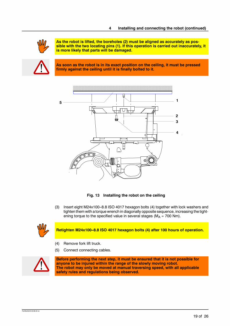
As the robot is lifted, the boreholes (2) must be aligned as accurately as pos-sible with the two locating pins (1). If this operation is carried out inaccurately, itis more likely that parts will be damaged.
As soon as the robot is in its exact position on the ceiling, it must be pressedfirmly against the ceiling until it is finally bolted to it.
1
2
4
5
3
Fig. 13 Installing the robot on the ceiling
(3) Insert eight M24x100--8.8 ISO 4017 hexagon bolts (4) together with lock washers andtighten themwith a torquewrench in diagonally opposite sequence, increasing the tight-ening torque to the specified value in several stages (MA = 700 Nm).
Retighten M24x100--8.8 ISO 4017 hexagon bolts (4) after 100 hours of operation.
(4) Remove fork lift truck.
(5) Connect connecting cables.
Before performing the next step, it must be ensured that it is not possible foranyone to be injured within the range of the slowly moving robot.The robot may only be moved at manual traversing speed, with all applicablesafety rules and regulations being observed.

Installation, Connection, Exchange
20 of 26
Ro/Me/03/23 03.99.02 en
(6) Put robot into operation and move it into a suitable position to install end--effector andadditional equipment.
Turn main switch on the robot control cabinet to “OFF” and secure it with a pad-lock to prevent unauthorized persons from switching it on again.
(7) Install end--effector and additional equipment.
If any additional equipment (working range monitoring devices, etc.) is installedon the robot, the instructions and warnings in the relevant Doc. Modules mustbe strictly observed.
(8) Connect all other cables which have been removed.
(9) Put robot into operation.

5 Exchange
21 of 26
Ro/Me/03/23 03.99.02 en
5 Exchange
To avoid the need for any major reprogramming after an exchange, the instructions given inthe Operating Handbook, Software KR C1A, Chapter “Start--up”, Section “Robot Mastering/Unmastering” must be accurately carried out every time a robot is exchanged.
5.1 Exchanging floor--mounted robots
D Removal
Turn main switch on the robot control cabinet to “OFF” and secure it with a pad-lock to prevent unauthorized persons from switching it on again.
(1) Remove end--effector (tool) and additional equipment.
The end--effector and additional equipment have to be removed if the robot is to bereplaced by another one or if they would otherwise impede the exchange work.
If the end--effector and additional equipment remain on the robot, this is liable tolead to adverse centers of gravity and collisions. The operator is deemedresponsible for any damage resulting in this respect.
Before performing the next step, it must be ensured that it is not possible foranyone to be injured within the range of the slowly moving robot.The robot may only be moved at manual traversing speed, with all applicablesafety rules and regulations being observed.
(2) Put robot into operation and move it into transport position (Fig. 14)*.
Installation, Connection, Exchange
22 of 26
Ro/Me/03/23 03.99.02 en
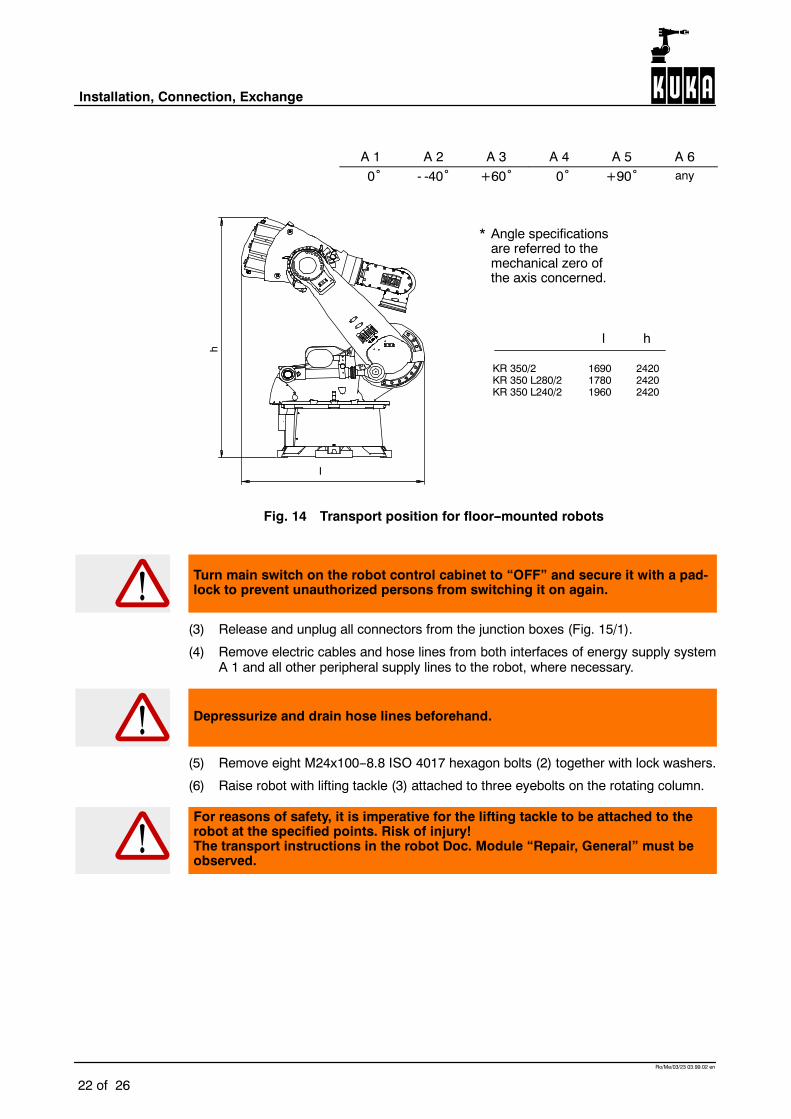
A 1 A 2 A 3 A 4 A 5 A 60˚ - -40˚ +60˚ 0˚ +90˚ any
* Angle specificationsare referred to themechanical zero ofthe axis concerned.
I
h
l h
KR 350/2 1690 2420KR 350 L280/2 1780 2420KR 350 L240/2 1960 2420
Fig. 14 Transport position for floor--mounted robots
Turn main switch on the robot control cabinet to “OFF” and secure it with a pad-lock to prevent unauthorized persons from switching it on again.
(3) Release and unplug all connectors from the junction boxes (Fig. 15/1).
(4) Remove electric cables and hose lines from both interfaces of energy supply systemA 1 and all other peripheral supply lines to the robot, where necessary.
Depressurize and drain hose lines beforehand.
(5) Remove eight M24x100--8.8 ISO 4017 hexagon bolts (2) together with lock washers.
(6) Raise robot with lifting tackle (3) attached to three eyebolts on the rotating column.
For reasons of safety, it is imperative for the lifting tackle to be attached to therobot at the specified points. Risk of injury!The transport instructions in the robot Doc. Module “Repair, General” must beobserved.

5 Exchange (continued)
23 of 26
Ro/Me/03/23 03.99.02 en
1
2
3
Fig. 15 Removal of floor--mounted robot
The robot can also be lifted by fork lift truck.
If the robot is transported by fork lift truck, the forks must be placed in the slotsin the base frame or the transport frame. It is forbidden to pick up the robot inany other way using a fork lift truck!
The robot must be lifted as vertically as possible until the locating pins are free.
(7) Lower robot onto a suitable support.
If the robot is not to be reinstalled for some time, it must be protected against corrosionbefore being put into storage.
D Installation
See Section 4.1.

Installation, Connection, Exchange
24 of 26
Ro/Me/03/23 03.99.02 en
5.2 Exchanging ceiling--mounted robots
D Removal
Turn main switch on the robot control cabinet to “OFF” and secure it with a pad-lock to prevent unauthorized persons from switching it on again.
(1) Remove end--effector (tool) and additional equipment.
The end--effector and additional equipment have to be removed if the robot is to be re-placed by another one or if they would otherwise impede the exchange work.
If the end--effector and additional equipment remain on the robot, this is liable tolead to adverse centers of gravity and collisions. The operator is deemedresponsible for any damage resulting in this respect.
Before performing the next step, it must be ensured that it is not possible foranyone to be injured within the range of the slowly moving robot.The robot may only be moved at manual traversing speed, with all applicablesafety rules and regulations being observed.
(2) Put robot into operation and move it into transport position (Fig. 16)*.
A 1 A 2 A 3 A 4 A 5 A 6
0˚ - -40˚ +60˚ 0˚ +90˚ any
* Angle specificationsare referred to themechanical zero ofthe axis concerned.
I
h
l h
KR 350/2 1690 2420KR 350 L280/2 1780 2420KR 350 L240/2 1960 2420
Fig. 16 Transport position for ceiling--mounted robots

5 Exchange (continued)
25 of 26
Ro/Me/03/23 03.99.02 en
Turn main switch on the robot control cabinet to “OFF” and secure it with a pad-lock to prevent unauthorized persons from switching it on again.
(3) Release and unplug all connectors from the junction boxes (Fig. 17/2).
(4) Remove electric cables and hose lines from both interfaces of energy supply systemA 1 and all other peripheral supply lines to the robot, where necessary.
Depressurize and drain hose lines beforehand.
If the robot is transported by fork lift truck, the forks must be placed in the slotsin the base frame. It is forbidden to pick up the robot in any other way using afork lift truck!
(5) Move the forks (3) of the fork lift truck into the slots designed for them on the robot andpress robot firmly against the ceiling.
1 2
3
Fig. 17 Removal of ceiling--mounted robot

Installation, Connection, Exchange
26 of 26
Ro/Me/03/23 03.99.02 en
(6) Remove eight M24x100--8.8 ISO 4017 hexagon bolts (1) together with lock washers.
(7) Lower robot slowly without tilting it.
The robot must be lowered vertically downwards until both locating pins arefree.
(8) Suspend robot in transport frame and if it needs to be turned over into the floor--mount-ing position (base frame at bottom, arm at top), turn the robot togetherwith the trans-port frame.
If the robot is not to be reinstalled for some time, it must be protected against corrosionbefore being put into storage.
D Installation
See Section 4.2.