installation and users’ manual f-11e - morco products · installation and users’ manual f-11e...
TRANSCRIPT

INSTALLATION AND USERS’ MANUALF-11E
SUPER COMPACT ROOM SEALED WATER HEATER
10.005.856 02

3
CONTENTS/SOMMAIRE/INHOUDSOPGAVEENGLISH:USERS INSTRUCTIONS
1.- CONTROL PANEL ........................................................................................... 42.- STARTING UP THE APPLIANCE......................................................................... 43.- OPERATION ................................................................................................... 44.- MAINTENANCE ............................................................................................. 65.- FROST PROTECTION....................................................................................... 7
TECHNICAL INSTRUCTIONS6.- DESCRIPTION OF THE APPLIANCE ................................................................... 87.- TECHNICAL CHARACTERISTICS ....................................................................... 108.- FUNCTIONAL DIAGRAM................................................................................. 119.- ELECTRICAL DIAGRAM .................................................................................... 12
10.- APPLIANCE DIMENSIONS ............................................................................... 1311.- GENERAL INSTALLATION REQUIREMENTS ........................................................ 1412.- INSTALLATION INSTRUCTIONS........................................................................ 1613.- COMMISSIONING INSTRUCTIONS ................................................................. 19
FRANÇAIS:INSTRUCTIONS D’UTILISATION
1.- PANNEAU DE COMMANDE............................................................................ 202.- MISE EN SERVICE DE L’APPAREIL...................................................................... 203.- FONCTIONNEMENT ...................................................................................... 204.- MAINTENANCE ............................................................................................. 225.- PROTECTION ANTI-GEL................................................................................... 23
INSTRUCTIONS TECHNIQUES6.- DESCRIPTION DE L’APPAREIL............................................................................ 247.- CARACTÉRISTIQUES TECHNIQUES .................................................................. 268.- SCHÉMA FONCTIONNEL................................................................................ 279.- SCHÉMA ÉLECTRIQUE..................................................................................... 28
10.- COTES D’ENCOMBREMENT............................................................................ 2911.- CRITÈRES GÉNÉRAUX D’INSTALLATION ............................................................ 3012.- INSTRUCTIONS D’INSTALLATION..................................................................... 3213.- INSTRUCTIONS DE MISE EN SERVICE .............................................................. 35
NEDERLANS:GEBRUIKERS-INSTRUCTIES
1.- BEDIENINGSPANEEL ....................................................................................... 362.- TOESTEL IN GEBRUIK NEMEN......................................................................... 363.- BEDIENING.................................................................................................... 364.- ONDERHOUD ................................................................................................ 385.- VORSTPREVENTIE ........................................................................................... 39
TECHNISCHE INSTRUCTIES6.- BESCHRIJVING VAN HET TOESTEL ................................................................... 407.- TECHNISCHE EIGENSCHAPPEN ...................................................................... 428.- FUNCTIE SCHEMA.......................................................................................... 439.- ELEKTRISCH SCHEMA ..................................................................................... 44
10.- AFMETINGEN VAN HET TOESTEL .................................................................... 4511.- ALGEMENE INSTALLATIEVOORWAARDEN ........................................................ 4612.- INSTALLATIE-INSTRUCTIES ................................................................................ 4813.- INSTRUCTIES INBEDRIJFSTELLING..................................................................... 51
4
USER
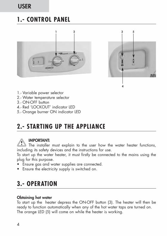
1.- Variable power selector 2.- Water temperature selector3.- ON-OFF button4.- Red ‘LOCKOUT’ indicator LED5.- Orange burner ON indicator LED
IMPORTANT: The installer must explain to the user how the water heater functions,
including its safety devices and the instructions for use.To start up the water heater, it must firstly be connected to the mains using theplug for this purpose.• Ensure gas and water supplies are connected.• Ensure the electricity supply is switched on.
Obtaining hot waterTo start up the heater depress the ON-OFF button (3). The heater will then beready to function automatically when any of the hot water taps are turned on.The orange LED (5) will come on while the heater is working.
1.- CONTROL PANEL
2.- STARTING UP THE APPLIANCE
3.- OPERATION
1 2 53
4
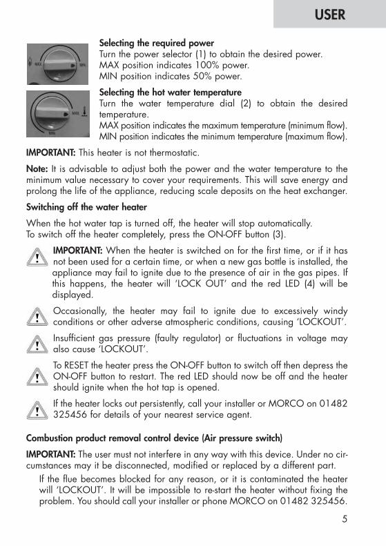
Selecting the required powerTurn the power selector (1) to obtain the desired power.MAX position indicates 100% power.MIN position indicates 50% power.
Selecting the hot water temperatureTurn the water temperature dial (2) to obtain the desiredtemperature.MAX position indicates the maximum temperature (minimum flow). MIN position indicates the minimum temperature (maximum flow).
IMPORTANT: This heater is not thermostatic.
Note: It is advisable to adjust both the power and the water temperature to theminimum value necessary to cover your requirements. This will save energy andprolong the life of the appliance, reducing scale deposits on the heat exchanger.
Switching off the water heater
When the hot water tap is turned off, the heater will stop automatically.To switch off the heater completely, press the ON-OFF button (3).
IMPORTANT: When the heater is switched on for the first time, or if it hasnot been used for a certain time, or when a new gas bottle is installed, theappliance may fail to ignite due to the presence of air in the gas pipes. Ifthis happens, the heater will ‘LOCK OUT’ and the red LED (4) will bedisplayed.
Occasionally, the heater may fail to ignite due to excessively windyconditions or other adverse atmospheric conditions, causing ‘LOCKOUT’.
Insufficient gas pressure (faulty regulator) or fluctuations in voltage mayalso cause ‘LOCKOUT’.
To RESET the heater press the ON-OFF button to switch off then depress theON-OFF button to restart. The red LED should now be off and the heatershould ignite when the hot tap is opened.
If the heater locks out persistently, call your installer or MORCO on 01482325456 for details of your nearest service agent.
Combustion product removal control device (Air pressure switch)
IMPORTANT: The user must not interfere in any way with this device. Under no cir-cumstances may it be disconnected, modified or replaced by a different part.
If the flue becomes blocked for any reason, or it is contaminated the heaterwill ‘LOCKOUT’. It will be impossible to re-start the heater without fixing theproblem. You should call your installer or phone MORCO on 01482 325456.
5
USER
6
USER
Note: before carrying out any maintenance or repair operations, the heater MUSTbe disconnected from the mains electric, and the gas and water supply.MORCO recommends yearly inspection of the heater by a qualified andcompetent service engineer.The following inspections should be carried out:• Check that the electrical installation is in good condition • Check for soundness of the gas and water installations.• Check for blockages and contamination of the flue assembly, especially
spiders webs and egg-sacks which can find their way along the flue and intothe venturii causing ‘LOCKOUT’.
• Check for correct gas pressure.• Check that the burner and heat exchanger are free of soot and other
contamination.
Cleaning the burnerRemove the burner and clean the bars with a soft brush or compressed air. Donot use chemical products.Remove the ignition and ionisation spark electrodes and clean the ends.The electrode unit should be replaced every three years.
Cleaning the heat exchangerClean the heat exchanger with hot water. If it is particularly dirty, leave it to soakin hot soapy water.Replace the heat exchanger seals when it is refitted.
Cleaning the coverClean the cover with a damp cloth. Do not use aggressive detergents.
Scale preventionIf the appliance is installed in a hard water area and if the following appear over time:• a reduction in the hot water temperature, or• a reduction in the hot water flowthis means that scale deposits have formed in the heat exchanger.To reduce this effect, we recommend obtaining the desired working temperatureby using the gas power control and the temperature selector, rather than bymixing cold water at the tap.
4.- MAINTENANCE
During freezing cold weather, the appliance must be drained down, leaving theappliance undrained during freezing conditions, will result in the appliance beingfrost damaged.It must be drained down in the following way: • Turn off the gas and electrical supply. • Turn off the mains water inlet stopcock. • Turn temperature control knob fully anticlockwise to minimum setting. • Turn on all hot and cold water taps. • Open all hot and cold drain cocks on the installation. Please refer to your
caravan owner’s handbook for the location of all drain cocks. • Disconnect the mains water inlet stopcock from the caravan pipework, this will
stop water refilling the pipework, if the stopcock fails due to frost damage. • Protect drain cocks and any open ended pipe from insects or debris. To turn the water on again, close all drain cocks, reconnect and open the mainswater inlet stopcock and turn off each hot and cold water taps as the water runsclear. We strongly recommend a qualified & competent service engineer is employedto do the drain down service.
7
USER
5.- FROST PROTECTION
INSTALLER
8
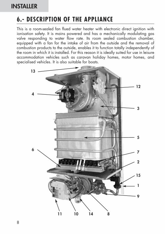
This is a room-sealed fan flued water heater with electronic direct ignition withionisation safety. It is mains powered and has a mechanically modulating gasvalve responding to water flow rate. Its room sealed combustion chamber,equipped with a fan for the intake of air from the outside and the removal ofcombustion products to the outside, enables it to function totally independently ofthe room in which it is installed. For this reason it is ideally suited for use in leisureaccommodation vehicles such as caravan holiday homes, motor homes, andspecialised vehicles. It is also suitable for boats.
6.- DESCRIPTION OF THE APPLIANCE
11
13
4
6
10
7
2
15
1
9
5
14 8
3
12
9
INSTALLER
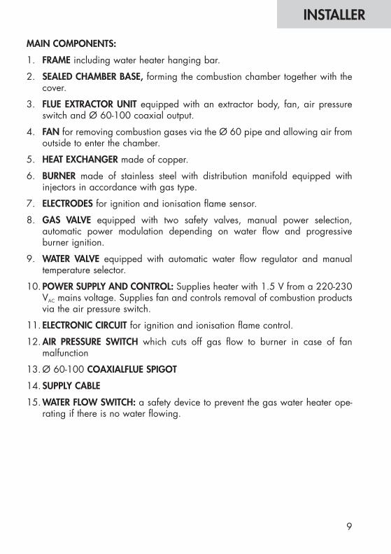
MAIN COMPONENTS:
1. FRAME including water heater hanging bar.
2. SEALED CHAMBER BASE, forming the combustion chamber together with thecover.
3. FLUE EXTRACTOR UNIT equipped with an extractor body, fan, air pressureswitch and Ø 60-100 coaxial output.
4. FAN for removing combustion gases via the Ø 60 pipe and allowing air fromoutside to enter the chamber.
5. HEAT EXCHANGER made of copper.
6. BURNER made of stainless steel with distribution manifold equipped withinjectors in accordance with gas type.
7. ELECTRODES for ignition and ionisation flame sensor.
8. GAS VALVE equipped with two safety valves, manual power selection,automatic power modulation depending on water flow and progressiveburner ignition.
9. WATER VALVE equipped with automatic water flow regulator and manualtemperature selector.
10. POWER SUPPLY AND CONTROL: Supplies heater with 1.5 V from a 220-230VAC mains voltage. Supplies fan and controls removal of combustion productsvia the air pressure switch.
11. ELECTRONIC CIRCUIT for ignition and ionisation flame control.
12. AIR PRESSURE SWITCH which cuts off gas flow to burner in case of fanmalfunction
13. Ø 60-100 COAXIALFLUE SPIGOT
14. SUPPLY CABLE
15. WATER FLOW SWITCH: a safety device to prevent the gas water heater ope-rating if there is no water flowing.

INSTALLER
Connector dimensions and pipe diametersGas inlet Natural 3/4”
Connections / inner Ø (mm) Butane-Propane 3/4”Cold Water Inlet 3/4”Hot Water Outlet 1/2”
Flue outlet (mm) Ø 60-100
Symbol Units Model F-11EPower and energy consumptionNominal output power Pn 19,2Mínimum output power Pmin. 6,7Power modulation range Pmin.- Pn kW 6,7-19,2Nominal energy consumption Qn 22,1Minimum energy consumption Qmin. 8,7Gas data
2 H Natural G20 202 E+ Natural G20/G25 20-25
Connection pressure 3+ Butane G30 mbar 28-30Propane G31 37
3 B/P Butane G30 302 H/2 E+ Natural G20 Hi=9,45 kWh/m3
m3/h 2,34Natural G25 Hi=8,13 h/m3 2,32
Consumo de gas 3+/(3B/P) Butane G30 Hi=12,68 kWh/kg kg/h 1,74Propane G31 Hi=12,87 kWh/kg 1,72
2 H/2 E+ Natural G20 12,7Burner pressure at Natural G25 16nominal power 3+/(3B/P) Butane G30 mbar 27
Propane G31 33,5Water dataWater flow Δ 50°C l/min 2,3-5,5
Δ 25°C l/min 3,7-11Max. operating pressure bar 13Min. operating pressure Max. tp. selector bar 0,12
Max. tp. selector bar 0,18Combustion productsFlow g/s 16Temperature °C 170Electrical dataElectrical supply V/Hz 220-230V~50HzMaximum absorbed power W 35
Certification, Category and Type Modelo F-11EEC type test certificate 99BO814Category I2E+ I2H I3+ I3B/P
Country of destination BE,FR ES,GB,IE,IT,PT BE,ES,FR,GB,IE,IT,PT NLType C12
Degree of electrical protection IP-44
7.- TECHNICAL CHARACTERISTICS
10
INSTALLER
11
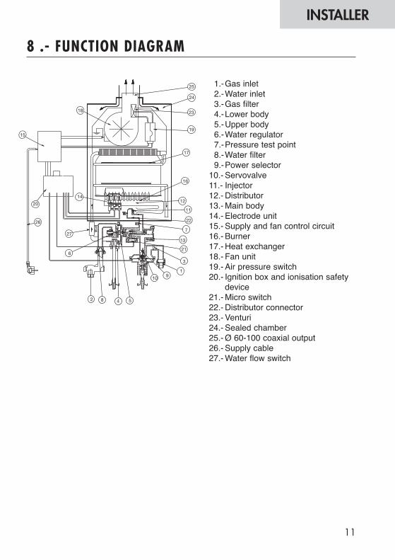
8 .- FUNCTION DIAGRAM
1.-Gas inlet 2.-Water inlet 3.-Gas filter4.-Lower body5.-Upper body6.-Water regulator7.-Pressure test point8.-Water filter9.-Power selector
10.- Servovalve11.- Injector12.- Distributor13.- Main body14.- Electrode unit15.- Supply and fan control circuit 16.- Burner17.- Heat exchanger18.- Fan unit19.- Air pressure switch 20.- Ignition box and ionisation safety
device21.- Micro switch22.- Distributor connector23.- Venturi24.- Sealed chamber 25.- Ø 60-100 coaxial output26.- Supply cable27.- Water flow switch
12
INSTALLER
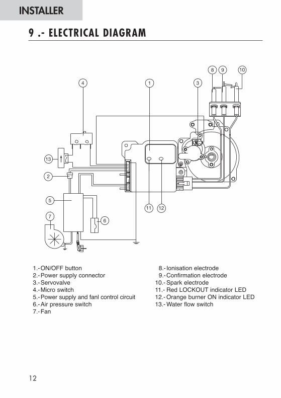
9 .- ELECTRICAL DIAGRAM
1.-ON/OFF button2.-Power supply connector3.-Servovalve4.-Micro switch5.-Power supply and fanl control circuit 6.-Air pressure switch 7.-Fan
8.- Ionisation electrode 9.-Confirmation electrode
10.- Spark electrode 11.- Red LOCKOUT indicator LED12.- Orange burner ON indicator LED13.- Water flow switch

13
INSTALLER
MODEL Weight Dimensions (mm)(kg) A B C D E F G H I J L M N O P Q R W X
11 Litre 15,5 330 595 230 247 60-100 25 122 230 8 50 513 50 61,5 592 75 14,5 143 125 143
10.- APPLIANCE DIMENSIONS
14
INSTALLER
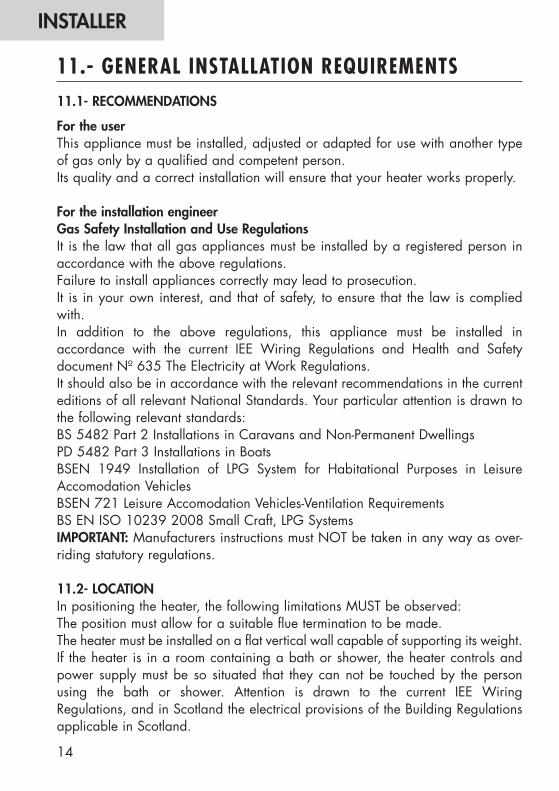
11.1- RECOMMENDATIONS
For the userThis appliance must be installed, adjusted or adapted for use with another typeof gas only by a qualified and competent person.Its quality and a correct installation will ensure that your heater works properly.
For the installation engineerGas Safety Installation and Use RegulationsIt is the law that all gas appliances must be installed by a registered person inaccordance with the above regulations.Failure to install appliances correctly may lead to prosecution.It is in your own interest, and that of safety, to ensure that the law is compliedwith.In addition to the above regulations, this appliance must be installed inaccordance with the current IEE Wiring Regulations and Health and Safetydocument Nº 635 The Electricity at Work Regulations.It should also be in accordance with the relevant recommendations in the currenteditions of all relevant National Standards. Your particular attention is drawn tothe following relevant standards:BS 5482 Part 2 Installations in Caravans and Non-Permanent DwellingsPD 5482 Part 3 Installations in BoatsBSEN 1949 Installation of LPG System for Habitational Purposes in LeisureAccomodation VehiclesBSEN 721 Leisure Accomodation Vehicles-Ventilation RequirementsBS EN ISO 10239 2008 Small Craft, LPG SystemsIMPORTANT: Manufacturers instructions must NOT be taken in any way as over-riding statutory regulations.
11.2- LOCATIONIn positioning the heater, the following limitations MUST be observed:The position must allow for a suitable flue termination to be made.The heater must be installed on a flat vertical wall capable of supporting its weight.If the heater is in a room containing a bath or shower, the heater controls andpower supply must be so situated that they can not be touched by the personusing the bath or shower. Attention is drawn to the current IEE WiringRegulations, and in Scotland the electrical provisions of the Building Regulationsapplicable in Scotland.
11.- GENERAL INSTALLATION REQUIREMENTS
15
INSTALLER
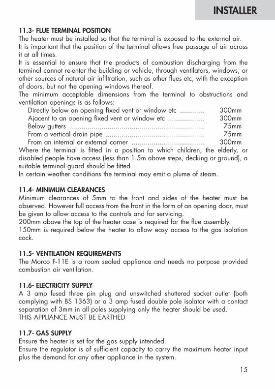
11.3- FLUE TERMINAL POSITIONThe heater must be installed so that the terminal is exposed to the external air.It is important that the position of the terminal allows free passage of air acrossit at all times.It is essential to ensure that the products of combustion discharging from theterminal cannot re-enter the building or vehicle, through ventilators, windows, orother sources of natural air infiltration, such as other flues etc, with the exceptionof doors, but not the opening windows thereof.The minimum acceptable dimensions from the terminal to obstructions andventilation openings is as follows:
Directly below an opening fixed vent or window etc ............ 300mmAjacent to an opening fixed vent or window etc .................. 300mmBelow gutters ................................................................... 75mmFrom a vertical drain pipe ................................................. 75mmFrom an internal or external corner .................................... 300mm
Where the terminal is fitted in a position to which children, the elderly, ordisabled people have access (less than 1.5m above steps, decking or ground), asuitable terminal guard should be fitted.In certain weather conditions the terminal may emit a plume of steam.
11.4- MINIMUM CLEARANCESMinimum clearances of 5mm to the front and sides of the heater must beobserved. However full access from the front in the form of an opening door, mustbe given to allow access to the controls and for servicing.200mm above the top of the heater case is required for the flue assembly.150mm is required below the heater to allow easy access to the gas isolationcock.
11.5- VENTILATION REQUIREMENTSThe Morco F-11E is a room sealed appliance and needs no purpose providedcombustion air ventilation.
11.6- ELECTRICITY SUPPLYA 3 amp fused three pin plug and unswitched shuttered socket outlet (bothcomplying with BS 1363) or a 3 amp fused double pole isolator with a contactseparation of 3mm in all poles supplying only the heater should be used.THIS APPLIANCE MUST BE EARTHED
11.7- GAS SUPPLYEnsure the heater is set for the gas supply intended.Ensure the regulator is of sufficient capacity to carry the maximum heater inputplus the demand for any other appliance in the system.
INSTALLER
16
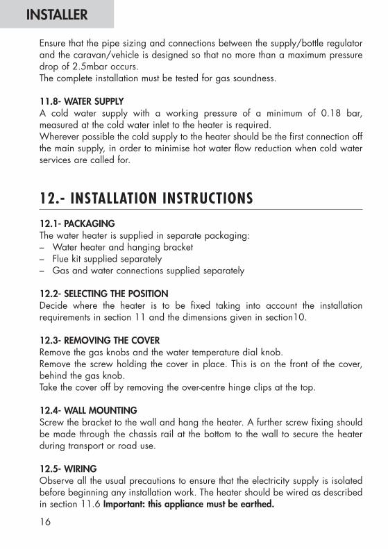
Ensure that the pipe sizing and connections between the supply/bottle regulatorand the caravan/vehicle is designed so that no more than a maximum pressuredrop of 2.5mbar occurs.The complete installation must be tested for gas soundness.
11.8- WATER SUPPLYA cold water supply with a working pressure of a minimum of 0.18 bar,measured at the cold water inlet to the heater is required.Wherever possible the cold supply to the heater should be the first connection offthe main supply, in order to minimise hot water flow reduction when cold waterservices are called for.
12.- INSTALLATION INSTRUCTIONS
12.1- PACKAGINGThe water heater is supplied in separate packaging:– Water heater and hanging bracket– Flue kit supplied separately– Gas and water connections supplied separately
12.2- SELECTING THE POSITION Decide where the heater is to be fixed taking into account the installationrequirements in section 11 and the dimensions given in section10.
12.3- REMOVING THE COVERRemove the gas knobs and the water temperature dial knob.Remove the screw holding the cover in place. This is on the front of the cover,behind the gas knob.Take the cover off by removing the over-centre hinge clips at the top.
12.4- WALL MOUNTINGScrew the bracket to the wall and hang the heater. A further screw fixing shouldbe made through the chassis rail at the bottom to the wall to secure the heaterduring transport or road use.
12.5- WIRING Observe all the usual precautions to ensure that the electricity supply is isolatedbefore beginning any installation work. The heater should be wired as describedin section 11.6 Important: this appliance must be earthed.

17
INSTALLER
12.6- WATER AND GAS CONNECTIONSThe water and gas pipes must be copper. Do not connect plastic pipes directly tothe heater. It is recommended that the copper is extended to below the floor ofthe caravan/vehicle before connecting to plastic.Ensure the gas pipe complies with the requirements in section 11.7.Remove any swarf or other residues in the pipes.Connect the heater using the corresponding joints and connectors supplied in thebag of accessories.Mount the cover and fix it to the appliance.Mount the gas and temperature dial knobs.
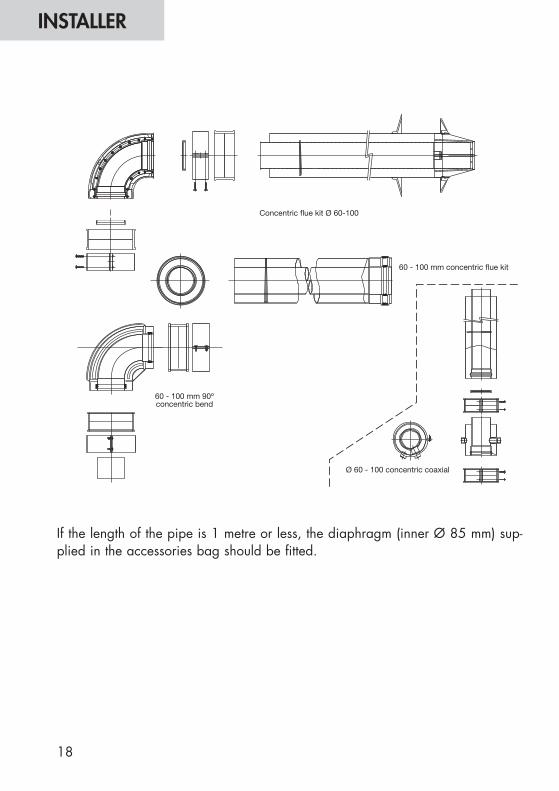
12.7- FLUE SYSTEMThe standard horizontal flue kit for the F-11E is part number RSF003. There arevarious other options available, including a vertical flue kit and other variationson the horizontal kit. Please ask for details. Never use a flue kit not specificallyapproved for use with this appliance.The horizontal pipe may be cut down to size to a minimum of 100 mm, to suitthe installation or extended to a maximum of a straight run of 4 meters. Elbowsare available but each will reduce the available length by 0.8 m.Installation in a caravan/vehicle will generally require only the use of part noRSF003.An external aluminium collar, part no RSF063 can be supplied to make the sealbetween the flue pipe and the external wall.
IMPORTANT:The flue assembly must be installed with a slight downwards incline to prevent theingress of rain water, which may damage the heater.
18
INSTALLER
If the length of the pipe is 1 metre or less, the diaphragm (inner Ø 85 mm) sup-plied in the accessories bag should be fitted.
19
INSTALLER
Before commissioning, ensure that the whole gas installation is purged and testedfor soundness.
IMPORTANT: To prevent damage to the gas valve soundness testing of the systemmust only be done with the isolation cock on the heater in the closed position. Anyover pressure such as is allowable to carry out a pipe soundness test couldpossibly damage the heater.
13.1- SETTINGSBefore leaving the factory the heater is pre-set in accordance with the informationon the data plate. No adjustment is necessary and under no circumstances shouldany of the seals be broken.
13.2- GAS CIRCUITTurn on the gas supply and check for leaks downstream of the isolation cock usingleak detector spray.
13.3- WATER CIRCUITTurn on the water supply and check for leaks.
13.4- INITIAL OPERATIONOperate the heater as per the instructions in section 2 and 3 of this manual.
13.5- FINAL CHECKSRe-light and test for gas soundnessCarry out an operating gas pressure test to ensure maximum potentialperformance.
13.6- USERS INSTRUCTIONSUpon completion of testing the system the installer should:– Give the instructions to the user and explain how the heater works.– Demonstrate the operation of the heater.– Explain the LOCKOUT and how to re-set.– Stress the importance of an annual service by a qualified and competent ser-
vice engineer.– Explain to the user how to proceed in case of freezing cold weather (drain
down the water circuit, turn off the gas and electrical supply).Explain the precautions to be taken to avoid frost damage
13.- COMMISSIONING INSTRUCTIONS

For more detailed servicing information, workshop manuals, technical advice,spare parts, product training, please ring MORCO on 00 44 1482 325456 orcontact us at the address below. Our qualified registered advisors are readyto help you.
Pour plus d’informations sur les notices, les prescriptions techniques, les piè-ces détachées, la formation sur le produit, etc., veuillez appeler MORCO au00 44 1482 325456 ou nous contacter à l’adresse suivante. Nos technicienscertifiés sont à votre disposition.
Voor gedetaillerdere informatie omtrent onderhoud, reparatiehandleidingen,technische adviezen en product-training wordt u verzocht MORCO te bellen.Nr: 00 44 1482 325456 of met ons contact op te nemene op onderstaandadres. Onze gekwalificeerde bij de aangesloten adviseurs staan klaar om ute helpen.
MORCO PRODUCTS LTDMorco House
Riverview RoadBeverley
East YorkshireHU17 0LDENGLAND
Telephone Number: 01482 325456Fax Number: 01482 212869
Web Address: www.morcoproducts.co.uk