gb24 & gb30 - morco products
TRANSCRIPT
User & Installation Instructions
GB24 & GB30
preheatpreheatmin min
max
mode
reset
off status burner
max
e
GB24
Morco House, Riverview Road, Beverley, East Yorkshire, HU17 0LDMorco Products LtdTel: 01482 325456 Fax: 01482 212869Website: www.morcoproducts.co.uk
To Domestic Hot Water:
GB24/30 Minimum 8.0 kW (27,296 Btu/h)GB24 Maximum 24.2 kW (82,570 Btu/h)GB30 Maximum 30.3 kW (103,384 Btu/h)
To Central Heating:
GB24/30 Minimum 8.0 kW (27,296 Btu/h)GB24/30 Maximum 24.2 kW (82,570 Btu/h)
BOILER OUTPUT
UIN 209783 A03April 2014

2
Combination Boiler
Destination Country:
BE = Belgium CH = SwitzerlandCZ = Czech Republic ES = SpainFR = FranceGB = UK GR = Greece IE = IrelandIT = ItalyNL = NetherlandsPL = Poland PT = PortugalSI = Slovenia
Morco GB24 & GB30
3
CoNTENTS
SECTIoN PAGE
1 Users Instructions ..........................................................................................................................................4
2 GeneralSpecifications ...................................................................................................................................8
3 Technical Data ...............................................................................................................................................10
4 General Installation Requirements.................................................................................................................12
5 Installation Instructions ..................................................................................................................................14
6 Commissioning Instructions ...........................................................................................................................23
7 Routine Servicing Instructions .......................................................................................................................25
8 Fact Sheets ....................................................................................................................................................31
9 Fault Codes....................................................................................................................................................32
10 Combustion Ratio Check ...............................................................................................................................34
11 Warranty ........................................................................................................................................................36
4
SECTION 1 - USERS INSTRUCTIONS
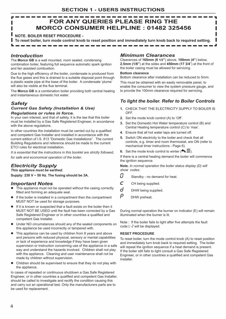
Minimum ClearancesClearances of 165mm (6 1/2”) above, 100mm (4”) below, 2.5mm (1/8”) at the sides and 450mm (17 3/4”) at the front of the boiler casing must be allowed for servicing.Bottom clearanceBottom clearance after installation can be reduced to 5mm. This must be obtained with an easily removable panel, to enable the consumer to view the system pressure gauge, and to provide the 100mm clearance required for servicing.
To light the boiler. Refer to Boiler Controls1. CheCK ThAT The eleCTRICITy SUPPly To BoIleR IS
oFF.2. Set the mode knob control (A) to ‘off’.3. Set the Domestic hot Water temperature control (B) and
Central heating temperature control (C) to ‘max’.4. ensure that all hot water taps are turned off.5. Switch oN electricity to the boiler and check that all
controls, e.g. timer and room thermostat, are oN (refer to mechanical timer instructions - Page 6).
6. Set the mode knob control to winter ( ).If there is a central heating demand the boiler will commence the ignition sequence.Note. In normal operation the boiler status display (D) will show codes:
Standby - no demand for heat.
Ch being supplied.
DhW being supplied.
DhW preheat.
During normal operation the burner on indicator (e) will remain illuminated when the burner is lit.
Note:Iftheboilerfailstolightafterfiveattemptsthefaultcode will be displayed.
RESET PRoCEDURETo reset boiler, turn the mode control knob (A) to reset position and immediately turn knob back to required setting. The boiler will repeat the ignition sequence if a heat demand is present. If the boiler still fails to light consult a Gas Safe Registered Engineer,orinothercountriesaqualifiedandcompetentGasInstaller.
IntroductionThe Morco GB is a wall mounted, room sealed, condensing combination boiler, featuring full sequence automatic spark ignition and fan assisted combustion.Duetothehighefficiencyoftheboiler,condensateisproducedfromthefluegasesandthisisdrainedtoasuitabledisposalpointthrougha plastic waste pipe at the base of the boiler. A condensate ‘plume’ willalsobevisibleattheflueterminal.The Morco GB is a combination boiler providing both central heating and instantaneous domestic hot water.
SafetyCurrent Gas Safety (Installation & Use) Regulations or rules in force.In your own interest, and that of safety, it is the law that this boiler must be installed by a Gas Safe Registered engineer, in accordance with the above regulations.Inothercountriestheinstallationmustbecarriedoutbyaqualifiedand competent Gas Installer and installed in accordance with the current edition of I.S. 813 “Domestic Gas Installations”. The current Building Regulations and reference should be made to the current eTCI rules for electrical installation.It is essential that the instructions in this booklet are strictly followed, for safe and economical operation of the boiler.
Electricity SupplyThis appliance must be earthed.Supply: 230 V ~ 50 Hz. The fusing should be 3A.
Important Notes This appliance must not be operated without the casing correctly
fittedandforminganadequateseal. If the boiler is installed in a compartment then the compartment
mUST NoT be used for storage purposes. If it is known or suspected that a fault exists on the boiler then it
mUST NoT Be USeD until the fault has been corrected by a Gas SafeRegisteredEngineerorinothercountriesaqualifiedandcompetent Gas Installer.
Under No circumstances should any of the sealed components on this appliance be used incorrectly or tampered with.
This appliance can be used by children from 8 years and above and persons with reduced physical, sensory or mental capabilities or lack of experience and knowledge if they have been given supervision or instruction concerning use of the appliance in a safe way and understand the hazards involved. Children shall not play with the appliance. Cleaning and user maintenance shall not be made by children without supervision.
Children should be supervised to ensure that they do not play with the appliance.
In cases of repeated or continuous shutdown a Gas Safe Registered Engineer,orinothercountriesaqualifiedandcompetentGasInstaller,should be called to investigate and rectify the condition causing this and carry out an operational test. only the manufacturers parts are to be used for replacement.
FoR ANy qUERIES PLEASE RING THEMoRCo CoNSUMER HELPLINE : 01482 325456
NoTE. BoILER RESET PRoCEDURE - To reset boiler, turn mode control knob to reset position and immediately turn knob back to required setting.

5
SECTION 1 - USERS INSTRUCTIONS
BOILER CONTROLS
Operation
Winter conditions - i.e. CH and DHW required.ensure the mode knob control (A) is set to winter ( ) Theboilerwillfireandsupplyheattotheradiatorsbutwillgivepriority to DhW on demand.
Summer conditions - i.e. DHW only required.Set the mode knob control to Summer ( ).
Set the Ch external controls to oFF.
Note. The pump will operate briefly as a self-check once every 24 hours, regardless of system demand.
Pre-heat is enabled if the pre-heat indicator (F) is lit. To switch pre-heat on or off move the DhW/Pre-heat control knob (B) fully clockwise and then return it to the required DhW temperature setting.
Control of water temperatureDomestic Hot WaterThe DhW temperature is limited by the boiler controls to 64oC maximum at low draw-off rate, adjustable via the DhW temperature control (B).
DuetosystemvariationsandseasonaltemperaturefluctuationsDHWflowrates/temperaturerisewillvary,requiringadjustmentat the draw off tap : the lower the rate the higher the temperature, and vice versa.
Central HeatingThe boiler controls the central heating radiator temperature to a maximum of 80oC and a minimum of 45ºC, adjustable via the Ch temperature control (C).
Theboilerisahighefficiencycombinationboilerwhichismostefficientwhenoperatingincondensingmode.
The boiler will operate in this mode if the Ch temperature control (C) is set to the ‘e’ position (economy mode). This control should be set to maximum for very cold periods
To shut down the boilerSet the mode knob control to oFF
To relight the boilerRepeat the procedure detailed in ‘To light the boiler’.
Frost protectionIf the holiday home or park home is to be left unoccupied during cold periods when there is a threat of freezing, the domestic hot and cold water circuits must be drained as follows:
- Turn off the cold water supply
- open all hot and cold water taps
- open all drain plugs in the hot and cold water system (do not drainthecentralheatingcircuit,whichshouldhavebeenfilledwith antifreeze if installed in a caravan holiday home or park home).
Refer to the holiday home or Park home owner’s handbook for the drain plug positions and further instructions on draining down.
Please note there are no drain plugs on the boiler. leave all taps and drain plugs open until next use to allow any residual water to continue to drain.
When installed in a Caravan holiday home or Park home the heatingcircuitandradiatorsshouldbefilledwithanapprovedantifreeze (see section 4.8). The level of antifreeze should be checked annually by a competent person. If the home is occupied during very cold and freezing weather, the central heating should be run continuously and the room stat or thermostatic radiator valves set at a minimum of 15ºC.
If the home is unoccupied for even a short period, the hot and cold water system must be drained down. This is the only way to guarantee against frost damage.
ALL FRoST DAMAGE IS oUTSIDE oF THE WARRANTy.
Boiler Overheat ProtectionThe boiler controls will shut down the boiler in the event of overheating. Should this occur, a fault code will be displayed.
Refer to fault chart.
Flame FailureShould this occur a fault code will be displayed. Refer to fault chart.
Approx.flowtemperaturesfortheboilerthermostatsettingsare:
Knob Setting Flow Temperature Minimum 40oC (104oF) Maximum 64oC (147oF)
continued . . . . . .
Legend
A. Mode Control KnobB. DHW/Preheat Control KnobC. CH Control KnobD. Boiler StatusE. Burner ‘on’ IndicationF. Pre Heat on/off IndicationG. Mechanical TimerH. Pressure GaugeJ.K.
Condensate DrainGas Isolation Valve(on position shown)
A B C D
G
H
JK
EF1920
21
2223
241
23
45 6 7 8
9
1011
1213
1415
1617
18
00I
preheatpreheatmin min
max
mode
reset
off status burner
max
e

6
SECTION 1 - USERS INSTRUCTIONS
To unblock a frozen condensate pipe;
1. Follow the routing of the plastic pipe from its exit point on the appliance, through its route to its termination point.
locate the frozen blockage. It is likely that the pipe is frozen at the most exposed point external to the building or where thereissomeobstructiontoflow.Thiscouldbeattheopenend of the pipe, at a bend or elbow, or where there is a dip in the pipe in which condensate can collect. The location of the blockageshouldbeidentifiedascloselyaspossiblebeforetaking further action.
2. Apply a hot water bottle, microwaveable heat pack or a warm damp cloth to the frozen blockage area. Several applications may have to be made before it fully defrosts. Warm water can also be poured onto the pipe from a watering can or similar. Do NoT use boiling water.
3. Caution when using warm water as this may freeze and cause other localised hazards.
4. Oncetheblockageisremovedandthecondensatecanflowfreely, reset the appliance. (Refer to “To light the boiler”)
5. If the appliance fails to ignite, call your Gas Safe Registered engineer, orinothercountriesaqualifiedandcompetentGasInstaller.
Preventative solutionsDuring cold weather, set the boiler stat to maximum, (must return to original setting once cold spell is over)Place the heating on continuous and turn the room stat down to 15ºC overnight. (Return to normal after cold spell).
Escape of gasShould a gas leak or fault be suspected contact the Gas Supplier without Delay. TURN oFF ALL GAS SUPPLIES.Do NOT search for gas leaks with a naked flame.
CleaningFor normal cleaning simply dust with a dry cloth. To remove stubborn marks and stains, wipe with a damp cloth andfinishoffwithadrycloth.DO NOT use abrasive cleaning materials.
MaintenanceThe appliance should be serviced at least once a year by a Gas SafeRegisteredEngineer,orinothercountriesaqualifiedandcompetent Gas Installer.
Loss of system water pressureThe pressure gauge indicates the central heating system pressure. If the pressure is seen to fall below the original installation pressure of 1-2 bar over a period of time then a water leak may be indicated. In this event re-pressurise the boiler. If unable to do so or if the pressure continues to drop a Gas SafeRegisteredEngineer,orinothercountriesaqualifiedandcompetent Gas Installer should be consulted. INDICaTED By “F1” (LOw waTER PRESSURE) - THE BOILER wILL NOT OPERaTE IF THE PRESSURE HaS REDUCED TO LESS THaN 0.3 BaR UNDER THIS CONDITION.
Condensate DrainThisapplianceisfittedwithasiphoniccondensatetrapsystemthat reduces the risk of the appliance condensate from freezing. however should the condensate pipe to this appliance freeze, please follow these instructions:a. If you do not feel competent to carry out the defrosting
instructions below please call your local Gas Safe Registered Engineer,orinothercountriesaqualifiedandcompetentGasInstaller for assistance.
b. If you do feel competent to carry out the following instructions please do so with care when handling hot utensils. Do not attempt to thaw pipework above ground level.
If this appliance develops a blockage in its condensate pipe, its condensate will build up to a point where it will make a gurgling noise prior to locking out an “l2” fault code. If the appliance is reset it will make a gurgling noise prior to it locking out on a failed ignition “l2” code.
MECHANICAL 24 HoUR TIMERPRoGRAMMING THE TIMER1. Decide what times you would like the timeswitch to switch oN and oFF.2. Push segments towards the programme ring for an oFF period and
push away from ring for an oN period. The minimum switching interval is 15 minutes and this can be increased in 15 minute steps.
3. Bring the timeswitch into the correct condition by manually turning the programme ring clockwise through a 24 hour cycle.
4. Turn the programme ring clockwise until the correct time of day on the ring lines up with the time indicator.
Note. The segment dial can be turned when the time controller is operating. In case of power failure, re-adjust the time controller to the correct time of day, turning the dial in a clockwise direction.
Permanent overrideBy rotating the central switch so that the symbol (1) lines up with the time indicator ( ) the unit will be permanently oN.With the symbol ( ) lining up with the time indicator ( ) the unit acts as a timeswitch.With the symbol ( ) lining up with the time indicator ( ) the unit will be permanently oFF.
192021
2223
241
23
45
6 7 89
1011
1213
1415
1617
18
Time & ControlIndicator
24hr Programme Ring
Timer control segments1 Segment = 15 minsPush towards programme ring = OFFPush away from programme ring = ON
OFF segment
ON segment
Permanently ON
Permanently OFF
Timer Control
PRESSURE GAUGE
192021
2223
241
23
45 6 7 8
9
1011
1213
1415
1617
18
00I
preheatpreheatmin min
max
mode
reset
off status burner
max
e

7
SECTION 1 - USERS INSTRUCTIONS
PoINTS FoR THE BoILER USERNote. In line with our current warranty policy we would ask that you check through the Troubleshooting guide to identify any problems external to the boiler prior to requesting a service engineers visit. Should the problem be found to be other than with the appliance we reserve the right to levy a charge for the visit, or for any pre-arranged visit where access is not gained by the engineer.
yeS
yeS
No HoT WATER
Check the mains switch (fused spur) is turned on and ensure
switch mode control knob (A) is in the summer or winter position
Is water coming out of the hot water tap when turned on?
No CENTRAL HEATING
Check the mains switch (fused spur) is turned on and ensure
switch mode control knob (A) is in the winter position
Does the boiler operate and provide central heating?
Check the time settings on the programmer are as you require
and adjust if necessary
Check the timer is in an “oN” position and the room thermostat
is turned up
No HoT WATER oR CENTRAL HEATING
Check the fused spur is turned on and ensure switch mode
control knob (A) is in the winter position
See boiler “operation modes” and “Fault Codes” section
Does the boiler have a display showing on the front control
panel?
See boiler “Fault Codes” section. If ‘0’ is displayed then contact morco if your appliance
is under warranty or a Gas Safe Registered engineer, or in othercountriesaqualifiedand
competent Gas Installer, if out of warranty.
yeS
No
Contact a Gas Safe Registered engineer, or in other countries aqualifiedandcompetentGas
Installer.
No
See boiler “operation modes” and “Fault Codes” section. If “0” is
displayed then contact a Gas Safe Registered engineer, or in other
countriesaqualifiedandcompetentGas Installer.
No
Contact a Gas Safe Registered engineer, or in other countries aqualifiedandcompetentGas
Installer.
TRoUBLESHooTING
DISPLAy CoDE oN BoILER DESCRIPTIoN
The boiler is in standby mode awaiting either a central heating call or hot water demand.
The boiler has a call for central heating but the appliance has reached the desired temperature set on the boiler.
The boiler has a call for hot water but the appliance has reached the desired temperature set on the boiler.
The boiler is operating in central heating mode.
The boiler is operating in pre heat mode.
The water in the cental heating circuit is less than 5ºC. If heating is switched on, this display code will change to “c”.
The boiler is operating in hot water mode.
oPERATIoN MoDES Note. These letters are permanently displayed while in that mode.

8
SECTION 2 - gENERAL SPECIFICATIONS
2.1 GENERAL SPECIFICATIoNSThe morco GB range of boilers are wall mounted, full sequence, automaticsparkignitionlowwatercontent,fannedflue,highefficiencycondensingcombinationboilers.
Note.Duetothehighefficiencyoftheboileraplumeofwatervapour will format the terminal during operation. The boiler is supplied for use with Propane only at 37mbar supply pressure. It is particularly suitable for caravan holiday home and park home use.
maximum heat output in either heating or hot water for the GB24 is 24.2kW (82,570 Btu/hr)
maximum heat output in heating mode for the GB30 is 24.2 kW (82,570 Btu/hr) with 30.3 kW (103,384 Btu/hr) available for hot water production.
Theboilerissuppliedwithastandardconcentricfluewithadditionalextensions,fluedeflectorandverticalfluekitsavailableas optional extras.
The boiler is suitable for connection to fully pumped, sealed heating systems oNly. Adequate arrangements for completely draining the system by provision of drain cocks must be provided in the installation pipework.
The boiler contains the following components:Cast Aluminium heat exchangerDomestic hot Water Plate heat exchangerDiverter ValveCirculating PumpPressure GaugeSafety Valve and Central heating expansion VesselAutomatic BypassDaily Pump and Diverter Valve exercisemechanical 24hr Timer
The boiler temperature controls are visible, located in the control panel. These enable the user to control both Ch and DhW temperatures independently. There is the additional feature of a DhW preheat facility. operating and fault codes are displayed on the status panel.
1 Expansion Vessel2 Pump3 Auto Air Vent4 Water Pressure Switch5 Flow Thermistor6 Return Thermistor7 Divertor Valve8 Fan9 Venturi10 DHW Plate Heat Exchanger11 Ignition Electrode12 Flame Detection Electrode13 Gas Valve14 Siphon / Trap15 DHW Flow Turbine16 System Pressure Gauge17 Sump Cover
Schematic Diagram 8
11
5
9
13
4
7
17
15 103
6
2
1
14
12
16
9
SECTION 2 - gENERAL SPECIFICATIONS
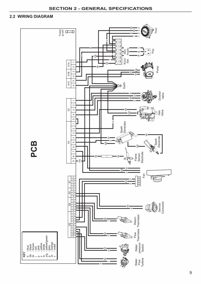
2.2 WIRING DIAGRAM
r
b
bkor
bk
1
X1A
Fuse
dat
4AT
X1B
X1C
X2
X3
X5
X6
X8
23
45
61
23
45
12
34
56
87
91
23
41
23
45
6
X7
12
34
51
23
45
67
89
1011
Wat
erFl
owTu
rbin
e
pbkrbk
Wat
erpr
essu
reS
witc
h
PCB
Flow
Ther
mis
tor
Ret
urn
Ther
mis
tor
Ear
th
y/g
br
bbk
bk
b
bbr
y/g
Ser
vice
Con
nect
or
- blu
e- b
lack
- bro
wn
- red
- pin
k- y
ello
w- w
hite
- yel
low
/gre
en- g
rey
- ora
nge
- vio
let
b bk br r p y w y/g
g or vKEY
py
Flam
eS
enso
rE
lect
rode
Fan
bkbkbk
b
y/g
bry/
g
y/g
Spa
rkE
lect
rode
Spa
rkG
ener
ator
bk
Gas
Valv
e
b
bk
bbr
bkb
Div
erto
rVa
lve
Pum
p
bk
r
y/g
y/gb
b
Tim
erP
lugbr
r
r
N
bbk
bk
Roo
mS
tat
Mai
nS
uppl
y
12
34
L

10
section 3 - tecHnicAL DAtA
Note. Gas consumption is calculated using a calorific value of 95.65 MJ/m3 (2569 Btu/ft3) gross or 88.0 MJ/m3 (2,360 Btu/ft3) nett
To obtain the gas consumption at a different calorific value:a. For l/s - divide the gross heat input (kW) by
the gross C.V. of the gas (MJ/m3)b. For ft3/h - divide the gross heat input (Btu/h)
by the gross C.V. of the gas (Btu/ft3) c. For m3/h - multiply l/s by 3.6.
Key to symbols
PMS = maximum operating pressure of water
C13 C33 = A room sealed appliance designed for connection via ducts to a horizontal or vertical terminal, which admits fresh air to the burner and discharges theproductsofcombustiontotheoutsidethroughorificeswhich,inthiscase, are concentric. The fan is up stream of the combustion chamber.
I3P = An appliance designed for use on 3rd Family gas, Group P only.
* The value is used in the UK Government’s Standard Assessment Procedure (SAP) for energy rating of dwellings. The test data from whichithasbeencalculatedhavebeencertifiedbyanotifiedbody.
Morco GB 24 30Gas supply I3p - G31 - 37mbarGas Supply Connection 15mm copper compressionInjector Size (mm) 3.75 3.75Inlet Connection Domestic hot Water G 1/2
outlet Connection Domestic hot Water G 1/2
Flow Connection Central heating G 3/4
Return Connection Central heating G 3/4
Flue Terminal Diameter mm (in) 100 (4)Average Flue Temp-mass Flow Rate (DhW) 63oC - 11g/s 68oC - 13g/smaximum Working Pressure (Sealed Systems) bar (lb/in2) 2.5 (36.3)maximum Domestic hot Water Inlet Pressure bar (lb/in2) 10.0 (145)minimum Domestic hot Water Inlet Pressure* bar (lb/in2) 0.8 (11.6) 1.3 (18.9)electrical Supply 230 V ~ 50 hz. Power Consumption W 146 152Fuse Rating external : 3A Internal : T4h hRC l250 VWater content Central heating litre (gal) 1.2 (0.26)Domestic hot Water litre (gal) 0.5 (0.11)Packaged Weight kg (lb) 33.8 (74.4) 34.1 (75.2)maximum Installation Weight kg (lb) 31 (68.3) 31.2 (68.8)Boiler Casing Size height mm (in) 700 (27.5) Width mm (in) 395 (15.5) Depth mm (in) 285 (11.2)
Table 1 - General Data
*Required for maximum flow rate. Boiler operates down to 2 l/min DHW delivery
maximum DhW Input : 24 30 Nett CV kW 24.3 30.4
Btu/h 82,912 103,725
Gross CV kW 26.4 33
Btu/h 90,077 112,596
Gas Consumption m3/h 1.00 1.25
ft3/h 35.33 44.20
kg/hr 1.83 2.26
maximum kW 24.2 30.3
DhW output Btu/h 82,570 103,384
DhW Flow Rate l/min 9.9 12.4at 35°C temp. rise. gpm 2.2 2.8
DHWSpecificRate l/min 11.5 14.5 gpm 2.5 3.2
Boiler Input : Max. Min. 24 30 24 30Boiler Input ‘Q’ Nett CV kW 24.3 24.3 8.0 8.0 Btu/h 82,912 82,912 27,296 27,296 Gross CV kW 26.4 26.4 8.7 8.7 Btu/h 90,077 90,077 29,684 29,684 Gas Consumption m3/h 1.00 1.25 0.329 0.329 ft3/h 35.33 44.20 11.62 11.62 kg/hr 1.83 2.26 0.58 0.58Boiler output : Non Condensing kW 24.2 24.2 8.00 8.00 70oC mean Water temp. Btu/h 82,570 82,570 27,296 27,296 Condensing kW 25.6 25.6 8.5 8.5 40oC mean Water temp. Btu/h 87,347 87,347 29,002 29,002
Seasonalefficiency*SEDBUK2005 91% 91.1%Seasonalefficiency*SEDBUK2009 89% 89%NOxClassification CLASS5
Table 2 - Performance Data - Central Heating Table 3 - Performance Data - Domestic Hot Water
11
section 3 - tecHnicAL DAtA
3952.5 2.5from case
700
Sideflue
dim. A
285
86.5
17
155
CH F
LOW
DHW
OUT
LET
COND
. DRA
IN
GAS
INLE
T
DHW
INLE
T
CH R
ETUR
N
PRV
43.5 65 28.5 28.5 60.6 75 37.556.4
Underside View - Dimensions to WallW
A L
L
W A L L
99103 99 99 103
Table 3 - Performance Data - Domestic Hot Water
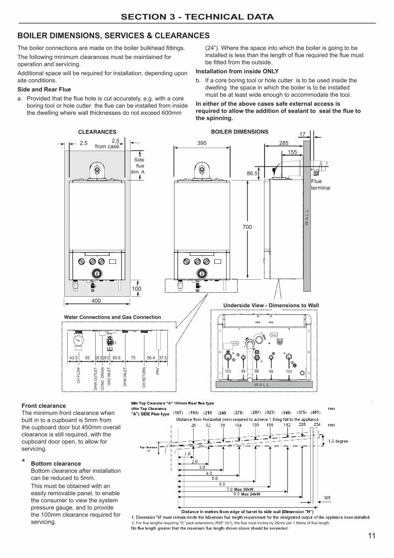
BoILER DIMENSIoNS, SERVICES & CLEARANCESTheboilerconnectionsaremadeontheboilerbulkheadfittings.The following minimum clearances must be maintained for operation and servicing.Additional space will be required for installation, depending upon site conditions.Side and Rear Fluea. Providedthattheflueholeiscutaccurately,e.g.withacore
boringtoolorholecutterthefluecanbeinstalledfrominsidethe dwelling where wall thicknesses do not exceed 600mm
(24”). Where the space into which the boiler is going to be installedislessthanthelengthoffluerequiredthefluemustbefittedfromtheoutside.
Installation from inside oNLyb. If a core boring tool or hole cutter is to be used inside the
dwelling the space in which the boiler is to be installed must be at least wide enough to accommodate the tool.
In either of the above cases safe external access is required to allow the addition of sealant to seal the flue to the spinning.
Front clearanceThe minimum front clearance when built in to a cupboard is 5mm from the cupboard door but 450mm overall clearance is still required, with the cupboard door open, to allow for servicing.
* Bottom clearance Bottom clearance after installation
can be reduced to 5mm. This must be obtained with an
easily removable panel, to enable the consumer to view the system pressure gauge, and to provide the 100mm clearance required for servicing.
Max 30kWMax 24kW
2.Forfluelengthsrequiring“D”packextensions(RSF341),thefluemustinclineby26mmper1Metreoffluelength.
12
SECTION 4 - gENEral INSTallaTION rEquIrEmENTS
4.1 RECoMMENDATIoNSCurrent Gas Safety (Installation and Use) Regulation or Rules in Force.Theboilerissuitableonlyforinstallationinthespecifiedcountriesand should be installed in accordance with the rules in force.In GB, the installation must be carried out by a Gas Safe RegisteredEngineer,orinothercountriesaqualifiedandcompetent Gas Installer. It must be carried out in accordance with the relevant requirement of the:• GasSafety(InstallationandUse)Regulations• AppropriateNationalStandards• TheWaterFittingsRegulations• CurrentIEEWiringRegulations• Health&SafetyDocumentNol.635• TheElectricityatworkRegulations1989.• BS5482Part1CodeofPracticeforDomesticbutaneand
propane gas burning installation in permanent dwellings, residential park homes and commercial premises.
• BSEN1949:2011SpecificationfortheinstallationofLPGSystems for habitation purposes in leisure accommodation vehicles and other road vehicles.
IMPoRTANTThe manufacturer’s notes mUST NoT be taken, in any way as overriding statutory obligations.
4.2 BoILER LoCATIoNTheboilermustbeinstalledonaflatandverticalwall,capableofadequately supporting the weight of the boiler and any ancillary equipment.Theboilermaybefittedonacombustiblewallandinsulationbetween the wall and the boiler is not necessary unless required by National Standards.For electrical Safety reasons there must be no access available from the rear of the boiler.Theboilermustnotbefittedoutside.
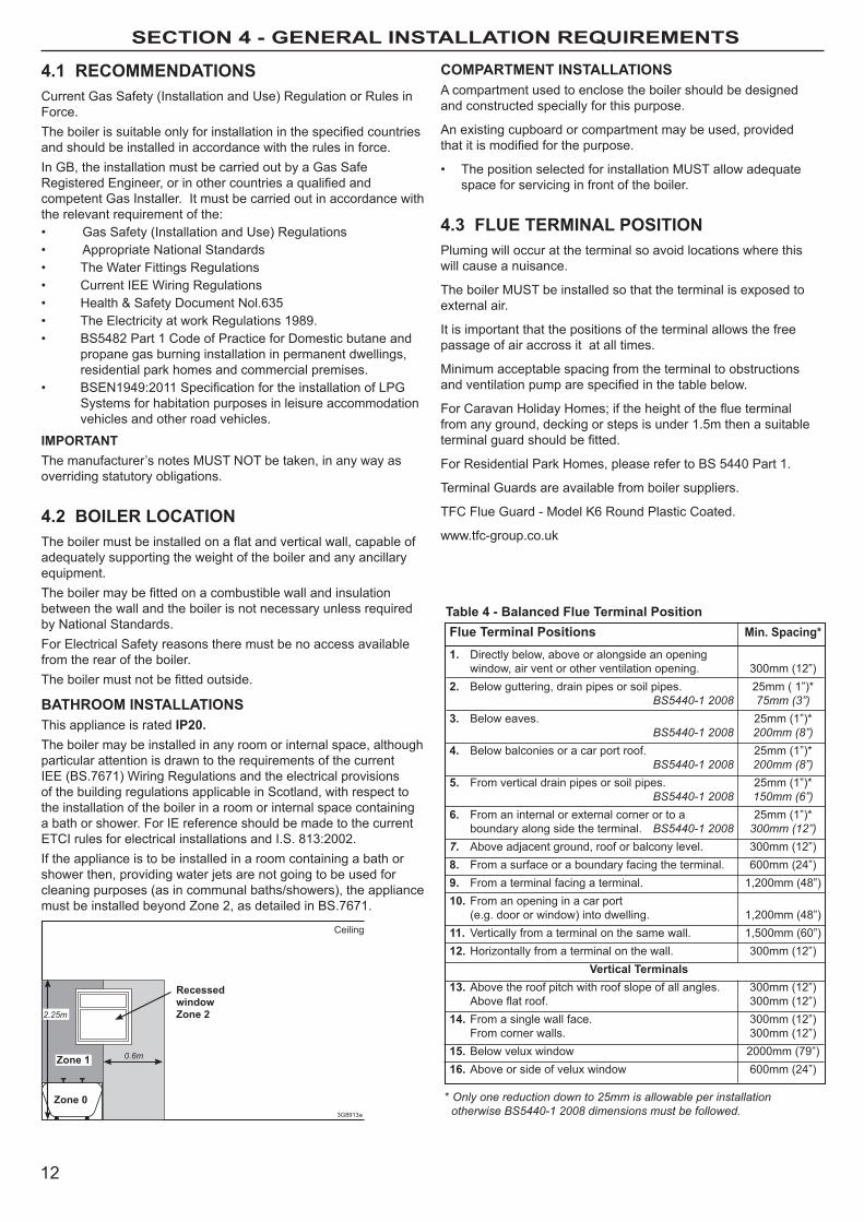
BATHRooM INSTALLATIoNSThis appliance is rated IP20. The boiler may be installed in any room or internal space, although particular attention is drawn to the requirements of the current Iee (BS.7671) Wiring Regulations and the electrical provisions of the building regulations applicable in Scotland, with respect to the installation of the boiler in a room or internal space containing a bath or shower. For Ie reference should be made to the current eTCI rules for electrical installations and I.S. 813:2002.If the appliance is to be installed in a room containing a bath or shower then, providing water jets are not going to be used for cleaning purposes (as in communal baths/showers), the appliance must be installed beyond Zone 2, as detailed in BS.7671.
0.6m
Zone 0
Recessed
window
Zone 2
Ceiling
3G8913a
2.25m
Zone 1
CoMPARTMENT INSTALLATIoNSA compartment used to enclose the boiler should be designed and constructed specially for this purpose.
An existing cupboard or compartment may be used, provided thatitismodifiedforthepurpose.
• ThepositionselectedforinstallationMUSTallowadequatespace for servicing in front of the boiler.
4.3 FLUE TERMINAL PoSITIoNPluming will occur at the terminal so avoid locations where this will cause a nuisance.
The boiler mUST be installed so that the terminal is exposed to external air.
It is important that the positions of the terminal allows the free passage of air accross it at all times.
minimum acceptable spacing from the terminal to obstructions andventilationpumparespecifiedinthetablebelow.
ForCaravanHolidayHomes;iftheheightoftheflueterminalfrom any ground, decking or steps is under 1.5m then a suitable terminalguardshouldbefitted.
For Residential Park homes, please refer to BS 5440 Part 1.
Terminal Guards are available from boiler suppliers.
TFC Flue Guard - model K6 Round Plastic Coated.
www.tfc-group.co.uk
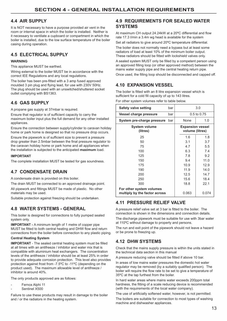
* Only one reduction down to 25mm is allowable per installation otherwise BS5440-1 2008 dimensions must be followed.
Flue Terminal Positions Min. Spacing*
1. Directly below, above or alongside an opening window, air vent or other ventilation opening. 300mm (12”)2. Below guttering, drain pipes or soil pipes. 25mm ( 1”)* BS5440-1 2008 75mm (3”)3. Below eaves. 25mm (1”)* BS5440-1 2008 200mm (8”)4. Below balconies or a car port roof. 25mm (1”)* BS5440-1 2008 200mm (8”)5. From vertical drain pipes or soil pipes. 25mm (1”)* BS5440-1 2008 150mm (6”)6. From an internal or external corner or to a 25mm (1”)* boundary along side the terminal. BS5440-1 2008 300mm (12”)7. Above adjacent ground, roof or balcony level. 300mm (12”)8. From a surface or a boundary facing the terminal. 600mm (24”)9. From a terminal facing a terminal. 1,200mm (48”)10. From an opening in a car port (e.g. door or window) into dwelling. 1,200mm (48”)11. Vertically from a terminal on the same wall. 1,500mm (60”)12. horizontally from a terminal on the wall. 300mm (12”) Vertical Terminals13. Above the roof pitch with roof slope of all angles. 300mm (12”) Aboveflatroof. 300mm(12”)14. From a single wall face. 300mm (12”) From corner walls. 300mm (12”)15. Below velux window 2000mm (79”)16. Above or side of velux window 600mm (24”)
Table 4 - Balanced Flue Terminal Position
13
SECTION 4 - gENEral INSTallaTION rEquIrEmENTS
4.4 AIR SUPPLyIt is NoT necessary to have a purpose provided air vent in the room or internal space in which the boiler is installed. Neither is it necessary to ventilate a cupboard or compartment in which the boiler is installed, due to the low surface temperature of the boiler casing during operation.
4.5 ELECTRICAL SUPPLyWARNINGThis appliance mUST be earthed.Wiring external to the boiler mUST be in accordance with the correct Iee Regulations and any local regulations.Theboilerhasbeenpre-fittedwitha3ampfusedapprovedmoulded3pinplugandflyinglead,forusewith230V50Hz.The plug should be used with an unswitched/shuttered socket outlet complying with BS1363.
4.6 GAS SUPPLyA propane gas supply at 37mbar is required.Ensurethatregulatorisofsufficientcapacitytocarrythemaximum boiler input plus the full demand for any other installed appliances.ensure the connection between supply/cylinder to caravan holiday home or park home is designed so that no pressure drop occurs.Ensurethepipeworkisofsufficientsizetopreventapressuredropgreaterthan2.5mbarbetweenthefinalpressureregulatortothe caravan holiday home or park home and all appliances when the installation is subjected to the anticipated maximum load.
IMPoRTANTThe complete installation mUST be tested for gas soundness.
4.7 CoNDENSATE DRAINA condensate drain is provided on this boiler.The drain mUST be connected to an approved drainage point.AllpipeworkandfittingsMUSTbemadeofplastic.Noothermaterials may be used.Suitable protection against freezing should be undertaken.
4.8 WATER SySTEMS - GENERALThis boiler is designed for connections to fully pumped sealed system only.IMPoRTANT - A minimum length of 1 metre of copper pipe MUSTbefittedtobothcentralheatingandDHWflowandreturnconnections from the boiler before connection to any plastic piping.Central Heating SystemIMPoRTANT-Thesealedcentralheatingsystemmustbefilledat all times with an antifreeze / inhibitor and water mix that is compatible with aluminium heat exchangers. The concentration levelsoftheantifreeze/inhibitorshouldbeatleast25%inorderto provide adequate corrosion protection. This level also provides protection against frost from -7.5ºC to -11ºC (depending on the product used). The maximum allowable level of antifreeze / inhibitorisaround40%.
The only products approved are as follows:
- Fernox Alphi 11- Sentinel X500
Failure to use these products may result in damage to the boiler and / or the radiators in the heating system.
4.9 REqUIREMENTS FoR SEALED WATER SySTEMSAtmaximumCHoutput24.24kWata20ºCdifferentialandflowrate 17.3 l/min a 3.4m wg head is available for the systemSet all radiators to give around 20ºC temperature differential.The boiler does not normally need a bypass but at least some radiatorsofloadatleast10%oftheminimumboileroutput.Theseradiatorsshouldbefittedwithlockshieldvalvesonly.AsealedsystemMUSTonlybefilledbyacompetentpersonusinganapprovedfillingloop(orotherapprovedmethod)betweenthemains water supply pipe and the central heating return pipe.Onceused,thefillingloopshouldbedisconnectedandcappedoff.
4.10 ExPANSIoN VESSELTheboilerisfittedwithan8litreexpansionvesselwhichissufficientforacoldfillcapacityofupto143litres.For other system volumes refer to table below.
Safety valve setting bar 3.0
Vessel charge pressure bar 0.5 to 0.75
System pre-charge pressure bar None 1.0
System volume Expansion vessel (litres) volume (litres)
25 1.6 1.8 50 3.1 3.7 75 4.7 5.5 100 6.3 7.4 125 7.8 9.2 150 9.4 11.0 175 10.9 12.9 190 11.9 14.0 200 12.5 14.7 250 15.6 18.4 300 18.8 22.1For other system volumes multiply by the factor across 0.063 0.074
4.11 PRESSURE RELIEF VALVEApressurereliefvalvesetat3barisfittedtotheboiler.Theconnection is shown in the dimensions and connection details.The discharge pipework must be suitable for use with 3bar water at 110ºC without damage to property and persons.The run and exit point of the pipework should not leave a hazard or be prone to freezing up.
4.12 DHW SySTEMSCheck that the mains supply pressure is within the units stated in the technical data section in this manualApressurereducingvalveshouldbefittedifabove10bar.In areas of low mains water pressures the domestic hot water regulatormayberemoved(byasuitablyqualifiedperson).Theboilerwillrequiretheflowratetobesettogiveatemperatureof35ºC at the tap furthest from the boiler.In hard water areas where mains water exceeds 200ppm total hardness,thefittingofascalereducingdeviceisrecommended(with the requirements of the local water company).Theuseofartificiallysoftenedwater,however,isnotpermitted.The boilers are suitable for connection to most types of washing machine and dishwasher appliances.
14
section 5 - installation instructions
5.1 BoILER PACKAGINGThe boilers are supplied in different packagings:
• Boiler
• FlueSystem(separate)
• HardwarePack(separate)
5.2 FITTING/MoUNTING THE BoILERDecidewheretheboileristobefixedonthewall,takingintoaccount installation requirements detailed in previous section.
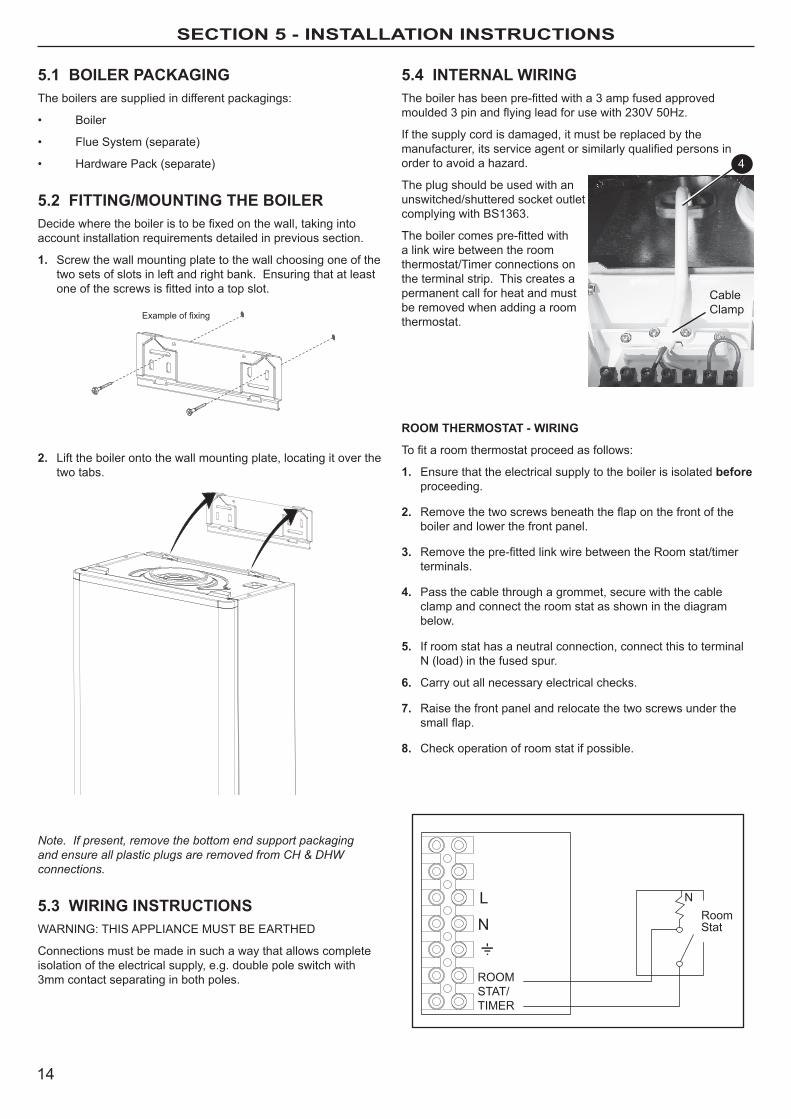
1. Screw the wall mounting plate to the wall choosing one of the two sets of slots in left and right bank. ensuring that at least oneofthescrewsisfittedintoatopslot.
2. lift the boiler onto the wall mounting plate, locating it over the two tabs.
Note. If present, remove the bottom end support packaging and ensure all plastic plugs are removed from CH & DHW connections.
5.3 WIRING INSTRUCTIoNSWARNING: ThIS APPlIANCe mUST Be eARTheD
Connections must be made in such a way that allows complete isolation of the electrical supply, e.g. double pole switch with 3mm contact separating in both poles.
NL
N
ROOMSTAT/TIMER
RoomStat
5.4 INTERNAL WIRINGTheboilerhasbeenpre-fittedwitha3ampfusedapprovedmoulded3pinandflyingleadforusewith230V50Hz.
If the supply cord is damaged, it must be replaced by the manufacturer,itsserviceagentorsimilarlyqualifiedpersonsinorder to avoid a hazard.
The plug should be used with an unswitched/shuttered socket outlet complying with BS1363.
Theboilercomespre-fittedwitha link wire between the room thermostat/Timer connections on the terminal strip. This creates a permanent call for heat and must be removed when adding a room thermostat.
RooM THERMoSTAT - WIRING
Tofitaroomthermostatproceedasfollows:
1. ensure that the electrical supply to the boiler is isolated before proceeding.
2. Removethetwoscrewsbeneaththeflaponthefrontoftheboiler and lower the front panel.
3. Removethepre-fittedlinkwirebetweentheRoomstat/timerterminals.
4. Pass the cable through a grommet, secure with the cable clamp and connect the room stat as shown in the diagram below.
5. If room stat has a neutral connection, connect this to terminal N (load) in the fused spur.
6. Carry out all necessary electrical checks.
7. Raise the front panel and relocate the two screws under the smallflap.
8. Check operation of room stat if possible.
Example of fixing
4
CableClamp
15
section 5 - installation instructions
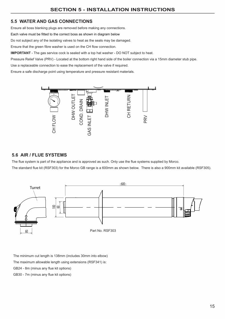
5.5 WATER AND GAS CoNNECTIoNSensure all boss blanking plugs are removed before making any connections.
Eachvalvemustbefittedtothecorrectbossasshownindiagrambelow
Do not subject any of the isolating valves to heat as the seals may be damaged.
EnsurethatthegreenfibrewasherisusedontheCHflowconnection.
IMPoRTANT - The gas service cock is sealed with a top hat washer - Do NoT subject to heat.
Pressure Relief Valve (PRV) - located at the bottom right hand side of the boiler connection via a 15mm diameter stub pipe.
Use a replaceable connection to ease the replacement of the valve if required.
ensure a safe discharge point using temperature and pressure resistant materials.
5.6 AIR / FLUE SySTEMSThefluesystemispartoftheapplianceandisapprovedassuch.OnlyusethefluesystemssuppliedbyMorco.
Thestandardfluekit(RSF303)fortheMorcoGBrangeisa600mmasshownbelow.Thereisalsoa900mmkitavailable(RSF305).
600Turret
60
60100
CH F
LOW DH
W O
UTLE
T
COND
. DRA
IN
GAS
INLE
T DHW
INLE
T
CH R
ETUR
N
PRV
Part No. RSF303
The minimum cut length is 138mm (includes 30mm into elbow)
The maximum allowable length using extensions (RSF341) is:
GB24-8m(minusanyfluekitoptions)
GB30-7m(minusanyfluekitoptions)
16
section 5 - installation instructions
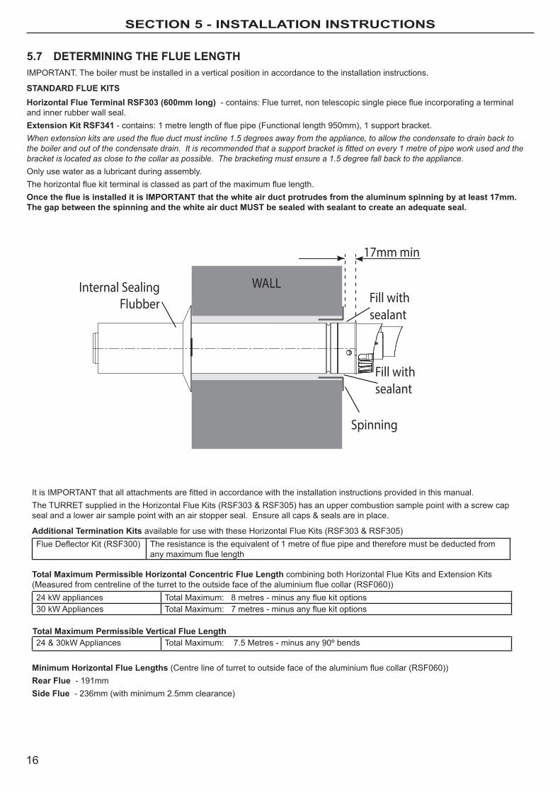
5.7 DETERMINING THE FLUE LENGTHImPoRTANT. The boiler must be installed in a vertical position in accordance to the installation instructions.
STANDARD FLUE KITSHorizontal Flue Terminal RSF303 (600mm long) -contains:Flueturret,nontelescopicsinglepieceflueincorporatingaterminaland inner rubber wall seal. Extension Kit RSF341 -contains:1metrelengthoffluepipe(Functionallength950mm),1supportbracket.When extension kits are used the flue duct must incline 1.5 degrees away from the appliance, to allow the condensate to drain back to the boiler and out of the condensate drain. It is recommended that a support bracket is fitted on every 1 metre of pipe work used and the bracket is located as close to the collar as possible. The bracketing must ensure a 1.5 degree fall back to the appliance.only use water as a lubricant during assembly.Thehorizontalfluekitterminalisclassedaspartofthemaximumfluelength.Once the flue is installed it is IMPORTANT that the white air duct protrudes from the aluminum spinning by at least 17mm. The gap between the spinning and the white air duct MUST be sealed with sealant to create an adequate seal.
WALL
Spinning
Fill withsealant
17mm min
Internal SealingFlubber
Fill withsealant
ItisIMPORTANTthatallattachmentsarefittedinaccordancewiththeinstallationinstructionsprovidedinthismanual.TheTURRETsuppliedintheHorizontalFlueKits(RSF303&RSF305)hasanuppercombustionsamplepointwithascrewcapsealandalowerairsamplepointwithanairstopperseal.Ensureallcaps&sealsareinplace.
Additional Termination KitsavailableforusewiththeseHorizontalFlueKits(RSF303&RSF305)FlueDeflectorKit(RSF300) Theresistanceistheequivalentof1metreoffluepipeandthereforemustbedeductedfrom
anymaximumfluelength
Total Maximum Permissible Horizontal Concentric Flue Length combining both horizontal Flue Kits and extension Kits(Measuredfromcentrelineoftheturrettotheoutsidefaceofthealuminiumfluecollar(RSF060))24 kW appliances TotalMaximum:8metres-minusanyfluekitoptions30 kW Appliances TotalMaximum:7metres-minusanyfluekitoptions
Total Maximum Permissible Vertical Flue Length24&30kWAppliances Total maximum: 7.5 metres - minus any 90º bends
Minimum Horizontal Flue Lengths (Centrelineofturrettooutsidefaceofthealuminiumfluecollar(RSF060))Rear Flue - 191mmSide Flue - 236mm (with minimum 2.5mm clearance)
17
section 5 - installation instructions
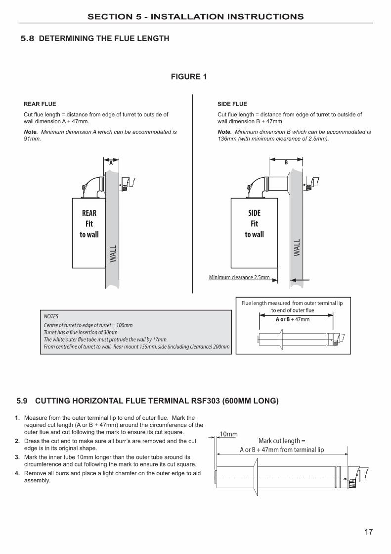
5.8 DETERMINING THE FLUE LENGTH
5.9 CUTTING HoRIZoNTAL FLUE TERMINAL RSF303 (600MM LoNG)
10mmMark cut length =
A or B + 47mm from terminal lip
1. Measurefromtheouterterminalliptoendofouterflue.Marktherequired cut length (A or B + 47mm) around the circumference of the outerflueandcutfollowingthemarktoensureitscutsquare.
2. Dress the cut end to make sure all burr’s are removed and the cut edge is in its original shape.
3. mark the inner tube 10mm longer than the outer tube around its circumference and cut following the mark to ensure its cut square.
4. Remove all burrs and place a light chamfer on the outer edge to aid assembly.
Centre of turret to edge of turret = 100mmTurret has a �ue insertion of 30mmThe white outer �ue tube must protrude the wall by 17mm.From centreline of turret to wall. Rear mount 155mm, side (including clearance) 200mm
NOTES
REARFit
to wall
A
Flue length measured from outer terminal lip to end of outer ue
A or B + 47mm
SIDEFit
to wall
B
Minimum clearance 2.5mm
WAL
L
WAL
L
FIGURE 1
REAR FLUE
Cutfluelength=distancefromedgeofturrettooutsideofwall dimension A + 47mm.
Note. Minimum dimension A which can be accommodated is 91mm.
SIDE FLUE
Cutfluelength=distancefromedgeofturrettooutsideofwall dimension B + 47mm.
Note. Minimum dimension B which can be accommodated is 136mm (with minimum clearance of 2.5mm).
18
section 5 - installation instructions
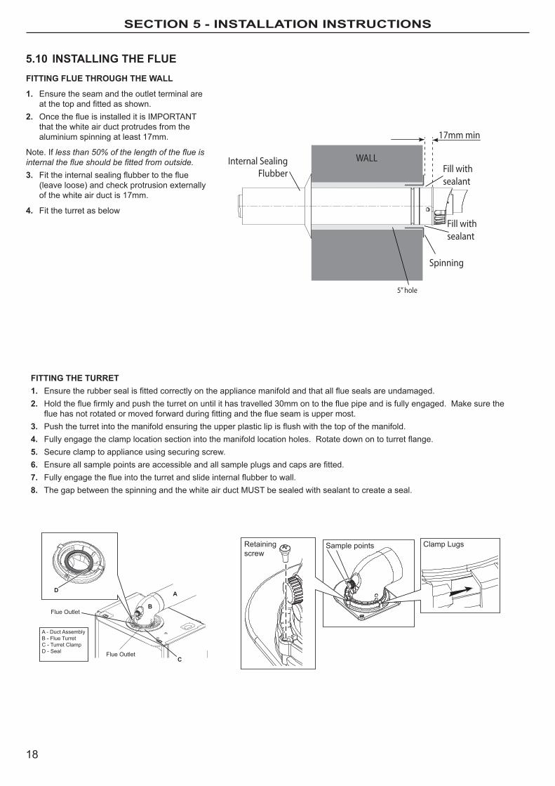
5.10 INSTALLING THE FLUEFITTING FLUE THRoUGH THE WALL
1. ensure the seam and the outlet terminal are atthetopandfittedasshown.
2. OncetheflueisinstalleditisIMPORTANTthat the white air duct protrudes from the aluminium spinning at least 17mm.
Note. If less than 50% of the length of the flue is internal the flue should be fitted from outside.3. Fittheinternalsealingflubbertotheflue
(leave loose) and check protrusion externally of the white air duct is 17mm.
4. Fit the turret as below
FITTING THE TURRET1. Ensuretherubbersealisfittedcorrectlyontheappliancemanifoldandthatallfluesealsareundamaged.2. Holdthefluefirmlyandpushtheturretonuntilithastravelled30mmontothefluepipeandisfullyengaged.Makesurethe
fluehasnotrotatedormovedforwardduringfittingandtheflueseamisuppermost.3. Pushtheturretintothemanifoldensuringtheupperplasticlipisflushwiththetopofthemanifold.4. Fullyengagetheclamplocationsectionintothemanifoldlocationholes.Rotatedownontoturretflange.5. Secure clamp to appliance using securing screw.6. Ensureallsamplepointsareaccessibleandallsampleplugsandcapsarefitted.7. Fullyengagetheflueintotheturretandslideinternalflubbertowall.8. The gap between the spinning and the white air duct mUST be sealed with sealant to create a seal.
Flue Outlet
C
A
A - Duct AssemblyB - Flue TurretC - Turret ClampD - Seal Flue Outlet
D
B
Retaining screw
Clamp LugsSample points
WALL
Spinning
Fill withsealant
17mm min
Internal SealingFlubber
Fill withsealant
5” hole

19
section 5 - installation instructions
5.11 FLUE ExTENSIoNS (RSF341) - oPTIoNAL
5.12 FLUE DEFLECToR KIT (RSF300) - oPTIoNAL
For side outlet refer to section 1.2 before connecting.
1. Makesurethat‘tophat’onthecollar(A)fitsovertherectangular form on the inner plastic pipe (B).
2. Ensurethattheflatbaseofthecollar(C)ispositioned on the bottom lip of the pipe (D).
INNER PIPE ASSEMBLy INSTRUCTIoNS
3. Slide the pipe and collar assembly back into the outer housing (e), note that this can only be done at the female end of the outer housing.
4. Whenfittingsupportbrackets(F)makesuretheyarepositioned on the female side of the neck as shown.
A B
Top hat
Rectangular
C D
E
F
ThefluedeflectorelbowcanbefittedtotheflueoutletofthestandardterminalkitsRSF303orRSF305todeflecttheflueproductshorizontallyto the left or the right only.
1. RefertotheboilerInstallationandServicingInstructionsforfittingoftheboileranditsfluesystem.
Note. The resistance of the deflector is equivalent to 1 metre of flue length. Ensure this is used when calculating the maximum allowable flue length.
2. Choosethedirectionrequiredtodeflecttheflueproducts(horizontally left or right only).
3. Pushthedeflectorelbowontotheangledflueoutletoftheterminalinthedesiredpositionandensurethedeflectorispusheduptotheshoulder to fully engage the rubber seal. Drill the terminal through theholeinthedeflectorwitha3.2mm(1/8")drillandsecurethedeflectorwiththeselftappingscrewprovided.
Note. Only use water as a lubricant during assembly. Do not use mineral based oils.
5.13 90º KIT RSF315 (oPTIoNAL)
This optional kit can be used on both horizontal and verticalfluekits
1. Use dimensions below for calculating total length
2. Whencuttingextensionsorfluekitsalwaysallowsufficient(+30mmairduct+14mmflueduct)toallowforcorrectengagementinthefitting
3. 1 elbow reduces the maximum available length by 1m
Note. Only use water as a lubricant during assembly . Do not use mineral based oils.
FlueDe�ector
WALL
115
115

20
section 5 - installation instructions
Note. A 5º or 14º pitched roof plate (not supplied) is required before proceeding with the installation of this kit.This kit is suitable for both 5º and 14º pitched roof terminations, usingaconcentricfluetorunverticallyfromthetopoftheboilerandterminating above roof level.Connection to the top of the boiler is made using a separately supplied vertical connector (RSF346).
WEATHER PRooFINGWherethefluepassesthroughtherooflineanadequatesealmustbemade. This is achieved by using a suitable sealant.
ACCESSoRIESFlueDuctExtensionKitsareavailableforfluelengthsextendingbeyond 1m. These packs contain 1m extension ducts and may be cut to the desired length. If 90º elbows are used (RSF315) they will reduce the overall height by 1m per elbow.
5.14 FITTING THE oPTIoNAL RooF FLUE KIT (RSF345) (Pitched)
Terminal Position Minimum Dimension Directly below an opening, air brick, windows, etc. 300 mm Below plastic / painted gutters 300 mm Painted surface 300 mm Below eaves or balcony 500 mm Below velux windows 2000mm Above or side of velux windows 600mm
5.15 ASSEMBLING THE RooF FLUE KIT1. Positiontheroofplate(suppliedseparately)overtheholecutintheroofandinsertflue
terminal from the roof end.
5º & 14ºMAX LENGTH:7.5m**
**minus any 90º bends
MIN LENGTH:0.950m
BOILER
2. ensure that if the length needs to be adjusted to allow an additional 30mm added to theouterairtubelength14mmaddedtotheinnerfluelength.Thisallowscorrectengagement into the vertical connector.
Note. ensure a square cut. remove all burrs and sharp edges.3. Fit the vertical connector (supplied separately) and secure the vertical connector by
applying downward pressure on the connector. 4. Positiontheclamponthetopfaceofthefluemanifoldandpushithorizontally
backwards.Locatebothclamplugsintothefluemanifoldandsecuretothefluemanifold clamp with the m5 retaining screw.
5. “Push” assembly A into vertical connector.Note. Ensure turret sample points are servicable and all caps and plugs are fitted.6. Finally ensure the roof plate is correctly sealed to the roof.
Flue Terminal
RSF05014º
RSF0505º
1
ASSEMBLy A
Assembly A5
3
Verticalconnector4
21
section 5 - installation instructions
5.16 CoNDENSATE DRAIN
137 156
CondensateDrain
CondensateDrain
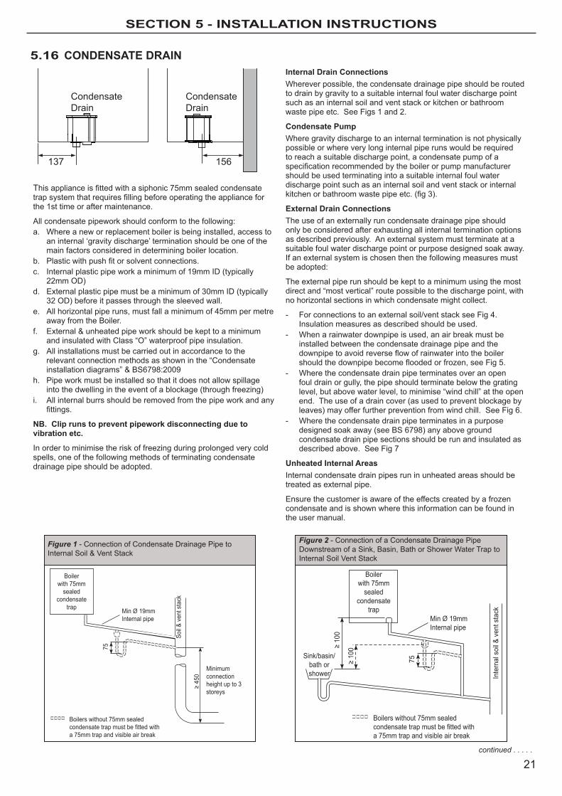
Thisapplianceisfittedwithasiphonic75mmsealedcondensatetrapsystemthatrequiresfillingbeforeoperatingtheapplianceforthe 1st time or after maintenance.
All condensate pipework should conform to the following:a. Where a new or replacement boiler is being installed, access to
an internal ‘gravity discharge’ termination should be one of the main factors considered in determining boiler location.
b. Plasticwithpushfitorsolventconnections.c. Internal plastic pipe work a minimum of 19mm ID (typically
22mm oD)d. external plastic pipe must be a minimum of 30mm ID (typically
32 oD) before it passes through the sleeved wall.e. All horizontal pipe runs, must fall a minimum of 45mm per metre
away from the Boiler.f. External&unheatedpipeworkshouldbekepttoaminimum
and insulated with Class “o” waterproof pipe insulation.g. All installations must be carried out in accordance to the
relevant connection methods as shown in the “Condensate installationdiagrams”&BS6798:2009
h. Pipe work must be installed so that it does not allow spillage into the dwelling in the event of a blockage (through freezing)
i. All internal burrs should be removed from the pipe work and any fittings.
NB. Clip runs to prevent pipework disconnecting due to vibration etc.
In order to minimise the risk of freezing during prolonged very cold spells, one of the following methods of terminating condensate drainage pipe should be adopted.
Internal Drain ConnectionsWherever possible, the condensate drainage pipe should be routed to drain by gravity to a suitable internal foul water discharge point such as an internal soil and vent stack or kitchen or bathroom waste pipe etc. See Figs 1 and 2.
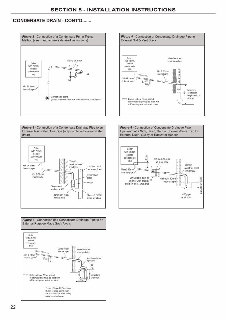
Condensate PumpWhere gravity discharge to an internal termination is not physically possible or where very long internal pipe runs would be required to reach a suitable discharge point, a condensate pump of a specificationrecommendedbytheboilerorpumpmanufacturershould be used terminating into a suitable internal foul water discharge point such as an internal soil and vent stack or internal kitchenorbathroomwastepipeetc.(fig3).
External Drain ConnectionsThe use of an externally run condensate drainage pipe should only be considered after exhausting all internal termination options as described previously. An external system must terminate at a suitable foul water discharge point or purpose designed soak away. If an external system is chosen then the following measures must be adopted:
The external pipe run should be kept to a minimum using the most direct and “most vertical” route possible to the discharge point, with no horizontal sections in which condensate might collect.
- For connections to an external soil/vent stack see Fig 4. Insulation measures as described should be used.
- When a rainwater downpipe is used, an air break must be installed between the condensate drainage pipe and the downpipetoavoidreverseflowofrainwaterintotheboilershouldthedownpipebecomefloodedorfrozen,seeFig5.
- Where the condensate drain pipe terminates over an open foul drain or gully, the pipe should terminate below the grating level, but above water level, to minimise “wind chill” at the open end. The use of a drain cover (as used to prevent blockage by leaves) may offer further prevention from wind chill. See Fig 6.
- Where the condensate drain pipe terminates in a purpose designed soak away (see BS 6798) any above ground condensate drain pipe sections should be run and insulated as described above. See Fig 7
Unheated Internal AreasInternal condensate drain pipes run in unheated areas should be treated as external pipe.
ensure the customer is aware of the effects created by a frozen condensate and is shown where this information can be found in the user manual.
Boilerwith 75mm
sealed condensate
trap Min Ø 19mm Internal pipe
Minimum connection height up to 3 storeys
Soil &
ven
t sta
ck
≥ 45
0
75
Boilers without 75mm sealed condensate trap must be fitted with a 75mm trap and visible air break
Sink/basin/bath orshower
Boilerwith 75mm
sealed condensate
trapMin Ø 19mm Internal pipe
Inte
rnal
soi
l & v
ent s
tack
Boilers without 75mm sealed condensate trap must be fitted with a 75mm trap and visible air break
75≥ 10
0≥ 10
0
Figure 1 - Connection of Condensate Drainage Pipe to InternalSoil&VentStack
Figure 2 - Connection of a Condensate Drainage Pipe Downstream of a Sink, Basin, Bath or Shower Water Trap to Internal Soil Vent Stack
continued . . . . .
22
section 5 - installation instructions
CoNDENSATE DRAIN - CoNT’D.......
Visible air break
Condensate pump(Install in accordance with manufacturers instructions)
Min Ø 19mm Internal pipe
Boilerwith 75mm
sealed condensate
trap
75
Min Ø 19mm Internal pipe
Min Ø 30mm Internal pipe
Air gap
External air break
combined foul/ rain water drain
Terminated and cut at 45º
43mm 90º male/ female bend
Water/weather proofinsulation
68mm Ø PVCUStrap on fitting
Boilerwith 75mm
sealed condensate
trap
Boilerwith 75mm
sealed condensate
trap
Min Ø 19mm Internal pipe
Min Ø 30mm Internal pipe
Water/Weather proof insulation
Max 3m external pipework
Limestonechippings
≥ 500
≥ 30
0
≥ 25
75
Boilers without 75mm sealed condensate trap must be fitted with a 75mm trap and visible air break
2 rows of three Ø12mm holes25mm centres, 50mm fromthe bottom of the tube, facingaway from the house
Minimum connection height up to 3 storeys
Soil &
ven
t sta
ck
≥ 45
0
Boilerwith 75mm
sealed condensate
trap
Min Ø 19mm Internal pipe
Min Ø 30mm Internal pipe
Water/weather proof insulation
75
Boilers without 75mm sealed condensate trap must be fitted with a 75mm trap and visible air break
Visible air breakat plug hole
Min Ø 19mm Internal pipe
Sink, basin, bath or shower with integral
overflow and 75mm trap
Minimum 30mminternal pipe
Water/weather proofinsulation
≥ 25
Bel
ow g
rate
45º pipetermination
Boilerwith 75mm
sealed condensate
trap
75
≥ 10
0
Figure 3 - Connection of a Condensate Pump Typical method (see manufacturers detailed instructions)
Figure 4 - Connection of Condensate Drainage Pipe to ExternalSoil&VentStack
Figure 5 - Connection of a Condensate Drainage Pipe to an external Rainwater Downpipe (only combined foul/rainwater drain)
Figure 7 - Connection of a Condensate Drainage Pipe to an external Purpose made Soak Away.
Figure 6 - Connection of Condensate Drainage Pipe Upstream of a Sink, Basin, Bath or Shower Waste Trap to external Drain, Gulley or Ranwater hopper

23
SECTION 6 - COMMISSIONING INSTRUCTIONS
Before commissioning the boiler, the whole gas installation including themeter(iffitted)MUSTbepurgedandtestedforgassoundness.
Purge air from the gas installation by the approved methods only.
WARNING. Whilst effecting the required gas soundness test and purging air from the gas installation, open all windows and doors, extinguish naked lights and Do NoT smoke.
Ensurethatthefluehasbeeninstalledcorrectlyandnoventsareblocked. Before commencing commissioning, ensure that the Ch systemandDHWandcoldwatersystemhavebeenflushed.TheCh system needs to be treated with water treatments that are approved for use with aluminium alloy heat exchangers.
GENERALPlease Note: The combustion for this appliance has been checked, adjusted and preset at the factory for operation on thegastypedefinedontheappliancedataplate.Aspartofthecommissioning process, the combustion of this appliance must be checked.Aflowcharttoassistisprovidedonpage35.
Do NoT adjust the air/gas ratio valve.
having checked:
- That the boiler has been installed in accordance with these instructions.
- Theintegrityofthefluesystemandtheflueseals,asdescribed in the Flue Installation section.
Proceed to put the boiler into operation as follows:
CHECK THE oPERATIoNAL (WoRKING) GAS INLET PRESSURESet up the boiler to operate at maximum rate by opening hot tap to maximum flow.
With the boiler operating in the maximum rate condition check that the operational (working) gas pressure at the inlet gas pressure test point complies with the requirements - refer to “Gas Supply” on page 13.
ensure that this inlet pressure can be obtained with all other gas appliances in the property working at maximum.
6.1 DoMESTIC HoT WATERTurn on the main cold water supply.Fill and vent the installation by turning on and off the various hot water taps in the installation.Check hot water taps in the installation.Check for and repair leaks as necessary.
LegendA. mode Control KnobB. DhW/Preheat ControlC. Ch Control
D. Boiler Statuse. Burner ‘on’ IndicationF. Pre heat on/off Indication
192021
2223
241
23
45 6 7 8
9
1011
1213
1415
1617
18
00I
preheatpreheatmin min
max
mode
reset
off status burner
max
e
A B C D
e
F
6.2 CENTRAL HEATING CIRCUITFill the siphon in the condense pipework prior to operating.In order for the boiler to function correctly, the pressure in the central heating circuit must be between 1 and 1.5 bar on the pressure gauge.Both the boiler and central heating installation must be purged of any air. The boiler has an auto air vent integral to the pump which must be loose prior to commissioning.Addanapprovedflushingsolutiontooneoftheradiators.Fill the central heating circuit using one of the approved methods to 1 bar.open radiator vent screws and turn off when water appears.Turnoffthefillingmethodanddisconnect.With the system hot, examine all water connections. The system pressure should not exceed 2.5 bar. Turn off gas, water and electricity when draining down.Refillandventthesystem,addinhibitorandanti-freezeintherequired concentration and check for water leaks.Check that the condensate operates and the pipework for any leaks.
6.3 INITIAL oPERATIoNensure central heating circuit is full and vented, and pressure gauge is reading 1.0 bar.
6.4 DoMESTIC HoT WATER MoDE
Turn the “mode” control knob to tap/radiator icon . ensure all external controls are calling for heat. Set the integral timer to oN.
Display reads “C” then “C” when burner is lit.
ensure all radiators warm up evenly. The Ch temperature can be controlledinbetweenmax80ºCandmin45ºC(flowtemp).
Check the DhW functions by turning on a hot water tap.
Close the DhW tap and set the integral timer and external controls to off.
Display will read “0”.
GasSupply
GasPressureTestPoint
24
SECTION 6 - COMMISSIONING INSTRUCTIONS
6.5 FINAL CHECKSRe-light and test for gas soundness.Set the Ch and DhW temperature knobs to the desired settings.ensure that the integral timer and/or room thermostat are set to the required settings.
6.6 HANDING oVERAfter completing the installation and commissioning of the system the installer should:• hand the Users Instruction to the owner and emphasise their
responsibilities under the relevant national regulations.• explain and demonstrate the lighting and shut down
procedures.• explain the operation of the boiler and the use and
adjustment of the system controls to ensure the greatest possible fuel economy, consistent with the owners heating and hot water requirements.
• Advise the user of the precautions necessary to prevent damage to the system and to the building in the event of the system remaining in operation during frosty condition.
• explain the function of the boiler fault mode. emphasise that if a fault is indicated, refer to Fault Codes in the User Guide.
• explain and demonstrate system controls, integral timer functions and boiler reset procedure.
IMPoRTANT - Stress the importance of an annual service by a competent gas registered engineer.
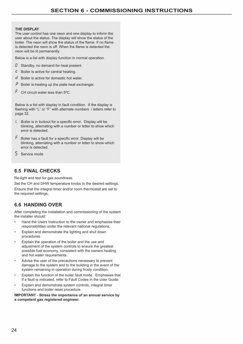
THE DISPLAyThe user control has one neon and one display to inform the user about the status. The display will show the status of the boiler.Theneonwillshowthestatusoftheflame.Ifnoflameisdetectedtheneonisoff.Whentheflameisdetectedtheneon will be lit permanently.
Below is a list with display function in normal operation.
0 Standby, no demand for heat present.
Boiler is active for central heating.
Boiler is active for domestic hot water.
Boiler is heating up the plate heat exchanger.
Ch circuit water less than 5ºC.
Below is a list with display in fault condition. If the display is flashingwith“L”or“F”withalternatenumbers/lettersrefertopage 32.
Boilerisinlockoutforaspecificerror.Displaywillbeblinking, alternating with a number or letter to show which error is detected.
Boilerhasafaultforaspecificerror.Displaywillbeblinking, alternating with a number or letter to show which error is detected.
Service mode

25
SECTION 7 - ROuTINE SERvICINg INSTRuCTIONS
7.1 SERVICING SCHEDULEFortheverylatestcopyofliteratureforspecification,maintenancepracticesandpartsreplacement,visitourwebsitewww.morcoproducts.co.ukwhere you will be able to download the relevant information.
waRNING. Always turn oFF the gas supply at the gas service cock, and switch oFF and disconnect the electricity supply to the appliance before servicing.Combustion testing must be carried out by a competent person using a combustion analyser conforming to BS7927.Toensurethecontinuedsafeandefficientoperationoftheapplianceitisrecommendedthatitischeckedatregularintervalsandserviced as necessary. The frequency of servicing will depend upon the installation condition and usage but should be carried out at least annually.
ItisthelawthatanyserviceworkmustbecarriedoutbyaGasSafeRegisteredEngineer,orinothercountriesaqualifiedandcompetent Gas Installer.
INSPECTIoN1. light the boiler and carry out a pre-service check, noting any
operational faults.
2.Checktheflueterminal(andterminalguardiffitted)isundamaged and clear of any obstruction.
3. Check all water and gas joints for signs of leakage. Remake any suspect joints ensuring a gas tightness check is carried outifapplicableandthewatersystemiscorrectlyrefilled,vented and re-pressurised.
CLEANING PRoCEDURENote. In order to carry out either servicing or replacement of
components the boiler upper and lower front panels must be removed. Refer to Frame 7.2.
1. Clean the main burner. Refer to Frame 7.4.
2. Cleantheheatexchanger&condensatetrap/siphon.RefertoFrames7.5&7.6.
3. Check the main injector for blockage or damage. Refer to Frame 7.3.
4. Checkthattheflueterminalisunobstructedandthatthefluesystem is sealed correctly.
The cleaning procedures are covered more fully in Frames 7.3-7.7 and mUST be carried out in sequence.
IMPoRTANT.5. After completing the servicing or exchange of components
always test for gas tightness.
6. When work is complete the front panels mUST be correctly refitted,ensuringthatagoodsealismade.
Do NOT OPERaTE the boiler if the upper front panel is not fitted.7. If, for any reason, the condensate trap/siphon has been
removedensurethetrapisrefilledwithwaterbefore reassembling.
8. Check the gas consumption if on metered installations.
9. CheckcombustionbyconnectingthefluegasanalysertothefluegassamplingpointasshowninthediagramandmeasureCO&CO2.
If the Co/Co2 ratio is greater than 0.004 AND the integrity of thecompletefluesystemandcombustioncircuitsealshavebeenverifiedandtheinletgaspressurehavebeenverified,then contact morco.
Flue Sampling Point
Air SamplePoint
Ensure all caps and sealsare re-fitted after use
GENERALPlease Note: During routine servicing, and after any maintenance or change of part of the combustion circuit, the following must be checked:
- Theintegrityofthefluesystemandtheflueseals,
- The integrity of the boiler combustion circuit and the relevant seals
- The operational (working) gas inlet pressure at maximum rate. Turn on one or more DhW taps.
- The combustion performance.
CoMPETENCE To CARRy oUT THE CHECK oF CoMBUSTIoN PERFoRMANCEPlease Note: BS6798:2009Specificationforinstallationandmaintenanceofgas-firedboilersofratedinputnotexceeding70kWnet advises that:
- The person carrying out a combustion measurement should have beenassessedascompetentintheuseofafluegasanalyserandthe interpretation of the results.
- Thefluegasanalyserusedshouldbeonemeetingtherequirements of BS7927 or BS-eN50379-3 and be calibrated in accordance with the analyser manufacturers requirements, and
- Competence can be demonstrated, for example, by satisfactory completion of the CPA1 ACS assessment (UK only), which covers the use of electronic portable combustion gas analysers in accordance with BS7967, Parts 1 to 4.
SERVICE MoDETo access the service mode:
Using the central heating potentiometer, starting from the 11 o’clock position, move the thumb piece to the maximum position, back to the 11o’clockpositionandthenfinallyfinishatthemaximumposition.The letter “S” will now be displayed.
To toggle to maximum DhW output move the thumb piece up to the 11 o’clock position and then back to maximum. A minimum of 3 seconds will reset the boiler back to normal mode.

26
SECTION 7 - ROuTINE SERvICINg INSTRuCTIONS
7.2 BoILER UPPER & LoWER FRoNT PANEL REMoVAL / REPLACEMENT
7.3 FAN AND VENTURI ASSEMBLy REMoVAL AND CLEANING
1. Disconnect the electrical leads from the fan.
2. Undo the gas pipe union connection to the injector housing.
3. Remove the extended nut on the fan mounting bracket.
4. lift off fan and venturi assembly.
5. Inspect the injector for blockage or damage.
6. Inspect fan outlet sealing gasket and replace if necessary.
1
2
3
5
Injector
REMoVAL
1. lift the lower front panel access panel.
2. Unscrewthetwofixingscrews,closetheaccesspaneltoretain the two screws and hinge the lower front panel down into the service position.
3. Removethetwoupperfrontpanelfixingscrews,liftthepanel and remove.
REPLACEMENT
4. hook the upper panel onto the top retaining clips.
5. Retaintheupperpanelwiththetwofixingscrewspreviously removed ensuring a good seal is made.
6. Swing the lower front panel up and retain with the two screws.
7. Close the lower front panel access panel.
2&6
1&7
3&5
27
SECTION 7 - ROuTINE SERvICINg INSTRuCTIONS
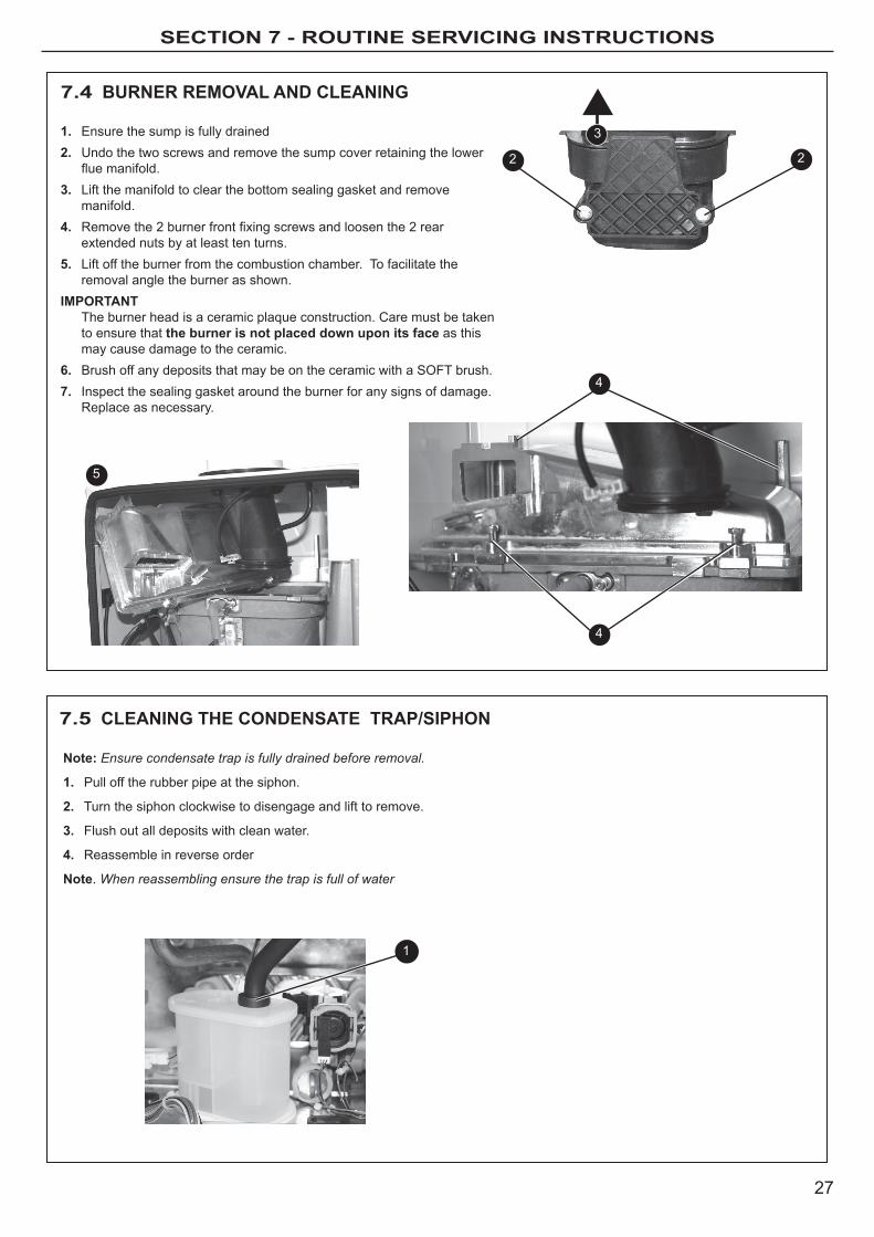
7.4 BURNER REMoVAL AND CLEANING
1. ensure the sump is fully drained2. Undo the two screws and remove the sump cover retaining the lower
fluemanifold.3. lift the manifold to clear the bottom sealing gasket and remove
manifold.4. Removethe2burnerfrontfixingscrewsandloosenthe2rear
extended nuts by at least ten turns.5. lift off the burner from the combustion chamber. To facilitate the
removal angle the burner as shown. IMPoRTANT
The burner head is a ceramic plaque construction. Care must be taken to ensure that the burner is not placed down upon its face as this may cause damage to the ceramic.
6. Brush off any deposits that may be on the ceramic with a SoFT brush.7. Inspect the sealing gasket around the burner for any signs of damage.
Replace as necessary.
Note: Ensure condensate trap is fully drained before removal.
1. Pull off the rubber pipe at the siphon.
2. Turn the siphon clockwise to disengage and lift to remove.
3. Flush out all deposits with clean water.
4. Reassemble in reverse order
Note. When reassembling ensure the trap is full of water
7.5 CLEANING THE CoNDENSATE TRAP/SIPHoN
3
2 2
4
4
5
1
28
SECTION 7 - ROuTINE SERvICINg INSTRuCTIONS
3
7.6 CLEANING THE HEAT ExCHANGER
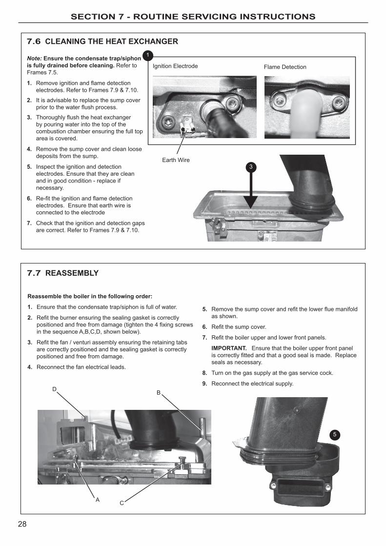
Note: Ensure the condensate trap/siphon is fully drained before cleaning. Refer to Frames 7.5.
1. Removeignitionandflamedetectionelectrodes.RefertoFrames7.9&7.10.
2. It is advisable to replace the sump cover priortothewaterflushprocess.
3. Thoroughlyflushtheheatexchangerby pouring water into the top of the combustion chamber ensuring the full top area is covered.
4. Remove the sump cover and clean loose deposits from the sump.
5. Inspect the ignition and detection electrodes. ensure that they are clean and in good condition - replace if necessary.
6. Re-fittheignitionandflamedetectionelectrodes. ensure that earth wire is connected to the electrode
7. Check that the ignition and detection gaps arecorrect.RefertoFrames7.9&7.10.
1
Ignition electrode
earth Wire
Flame Detection
Reassemble the boiler in the following order:
1. ensure that the condensate trap/siphon is full of water.
2. Refittheburnerensuringthesealinggasketiscorrectlypositionedandfreefromdamage(tightenthe4fixingscrewsin the sequence A,B,C,D, shown below).
3. Refitthefan/venturiassemblyensuringtheretainingtabsare correctly positioned and the sealing gasket is correctly positioned and free from damage.
4. Reconnect the fan electrical leads.
7.7 REASSEMBLy
5
A
5. Removethesumpcoverandrefitthelowerfluemanifoldas shown.
6. Refitthesumpcover.
7. Refittheboilerupperandlowerfrontpanels.
IMPoRTANT. ensure that the boiler upper front panel iscorrectlyfittedandthatagoodsealismade.Replaceseals as necessary.
8. Turn on the gas supply at the gas service cock.
9. Reconnect the electrical supply.
C
BD

29
SECTION 7 - ROuTINE SERvICINg INSTRuCTIONS
3
2 2
7.8 BURNER REMoVAL
4
4
1. Refer to Frame 7.3.2. Undo the two screws and remove the sump cover.3. lift the manifold to clear the bottom sealing gasket and remove
manifold.4. Removethe2frontfixingscrewsandloosenthe2rear
extended nuts.4. lift off the burner from the combustion chamber. To facilitate
the removal angle the burner as shown. 5. Fit the new burner, replacing any damaged or deteriorating
sealing gasket. 6. Reassemble in reverse order. 7. Check the operation of the boiler.
5
7.9 IGNITIoN ELECTRoDE
1. Remove the burner. Refer to Frame 7.8.
2. Check dimensions are correct as in diagram below..
3. Reassemble in reverse order.
FoR REMoVAL:1. Unplug the ignition lead and remove the
earth lead.
2. Remove the 2 retaining screws and remove the electrode.
3. Reassemble in reverse order replacing the gasket if necessary.
Ignition electrode
3mm
Straight e
dge
Spark Gap3.5mm
30
SECTION 7 - ROuTINE SERvICINg INSTRuCTIONS
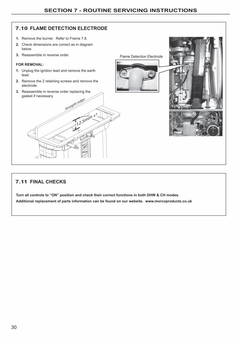
7.10 FLAME DETECTIoN ELECTRoDE
7.11 FINAL CHECKS
Flame Detection electrode
12.5mm
Straight e
dge
1. Remove the burner. Refer to Frame 7.8.
2. Check dimensions are correct as in diagram below.
3. Reassemble in reverse order.
FoR REMoVAL:1. Unplug the ignition lead and remove the earth
lead.
2. Remove the 2 retaining screws and remove the electrode.
3. Reassemble in reverse order replacing the gasket if necessary.
Turn all controls to “oN” position and check their correct functions in both DHW & CH modes.Additional replacement of parts information can be found on our website. www.morcoproducts.co.uk
31
SECTION 8 - fACT SHEETS
8 FACT SHEETS
There are a number of detailed fact sheets available for users to download from morco’s website.
Please visit www.morcoproducts.co.uk
The fact sheets can be located in the troubleshooting section and include:
- Winterisation of holiday homes
- Poor hot Water Delivery - Causes and Solutions
- low Central heating Pressure - Fault 1
- Thermostats, Programmers and Thermostatic Radiator Valves
- Combi boiler “cycling”
- Noisy boilers
SECTION 9 - faulT COdES
32
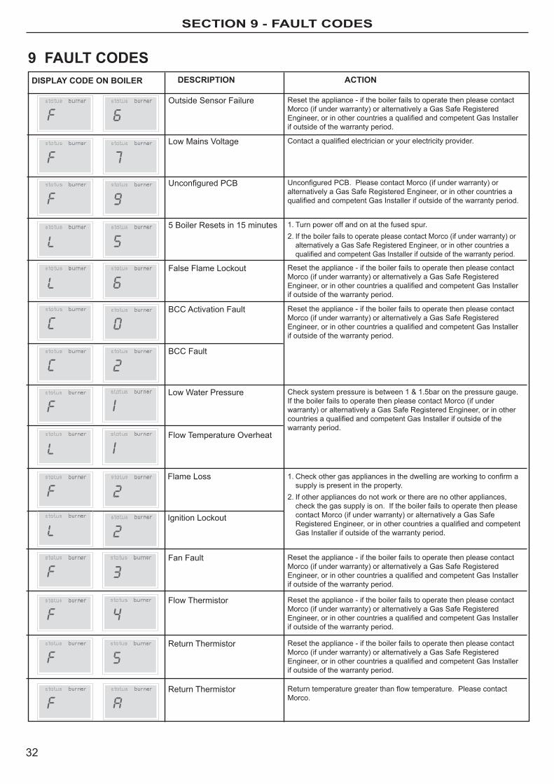
outside Sensor Failure Reset the appliance - if the boiler fails to operate then please contact morco (if under warranty) or alternatively a Gas Safe Registered Engineer,orinothercountriesaqualifiedandcompetentGasInstallerif outside of the warranty period.
low mains Voltage Contactaqualifiedelectricianoryourelectricityprovider.
UnconfiguredPCB UnconfiguredPCB.PleasecontactMorco(ifunderwarranty)oralternatively a Gas Safe Registered engineer, or in other countries a qualifiedandcompetentGasInstallerifoutsideofthewarrantyperiod.
5 Boiler Resets in 15 minutes 1. Turn power off and on at the fused spur.2. If the boiler fails to operate please contact morco (if under warranty) or
alternatively a Gas Safe Registered engineer, or in other countries a qualifiedandcompetentGasInstallerifoutsideofthewarrantyperiod.
False Flame lockout Reset the appliance - if the boiler fails to operate then please contact morco (if under warranty) or alternatively a Gas Safe Registered Engineer,orinothercountriesaqualifiedandcompetentGasInstallerif outside of the warranty period.
BCC Activation Fault Reset the appliance - if the boiler fails to operate then please contact morco (if under warranty) or alternatively a Gas Safe Registered Engineer,orinothercountriesaqualifiedandcompetentGasInstallerif outside of the warranty period.
DISPLAy CoDE oN BoILER DESCRIPTIoN
low Water Pressure
ACTIoN
Checksystempressureisbetween1&1.5baronthepressuregauge.If the boiler fails to operate then please contact morco (if under warranty) or alternatively a Gas Safe Registered engineer, or in other countriesaqualifiedandcompetentGasInstallerifoutsideofthewarranty period.
Flame loss
Ignition lockout
1.Checkothergasappliancesinthedwellingareworkingtoconfirmasupply is present in the property.
2. If other appliances do not work or there are no other appliances, check the gas supply is on. If the boiler fails to operate then please contact morco (if under warranty) or alternatively a Gas Safe RegisteredEngineer,orinothercountriesaqualifiedandcompetentGas Installer if outside of the warranty period.
Fan Fault Reset the appliance - if the boiler fails to operate then please contact morco (if under warranty) or alternatively a Gas Safe Registered Engineer,orinothercountriesaqualifiedandcompetentGasInstallerif outside of the warranty period.
Flow Thermistor Reset the appliance - if the boiler fails to operate then please contact morco (if under warranty) or alternatively a Gas Safe Registered Engineer,orinothercountriesaqualifiedandcompetentGasInstallerif outside of the warranty period.
Return Thermistor
Return Thermistor
Reset the appliance - if the boiler fails to operate then please contact morco (if under warranty) or alternatively a Gas Safe Registered Engineer,orinothercountriesaqualifiedandcompetentGasInstallerif outside of the warranty period.
Returntemperaturegreaterthanflowtemperature.Pleasecontactmorco.
9 FAULT CoDES
Flow Temperature overheat
BCC Fault

33

SECTION 10 - COMBUSTION CHECK
34
FLOWCHART FOR CO LEVEL AND COMBUSTION RATIOCHECK ON COMMISSIONING A CONDENSING BOILER
Important Preliminary Information on ChecksThe air gas ratio valve is factory-set and must not be adjusted DURING COMMISSIONING.
PRIOR TO CO LEVEL AND COMBUSTION RATIO CHECK
The installation instructions must have been followed, gas type verified and gas supply pressure / gas rate checked as required prior to commissioning.
As part of the installation process, ESPECIALLY WHERE A FLUE HAS BEEN FITTED BY PERSONS OTHER THAN THE BOILER INSTALLER, visually check the integrity of the whole flue system to confirm that all components are correctly assembled, fixed and supported. Check that maximum flue lengths have not been exceeded and all guidance has been followed (e.g. Gas Safe Register Technical Bulletin (TB) 008 where chimney/flues are in voids).
The ECGA should be of the correct type, as specified by BS 7967.
Prior to its use, the ECGA should have been maintained and calibrated as specified by the manufacturer. The installer must have the relevant competence for use of the analyser.
Check and zero the analyser IN FRESH AIR in accordance with the analyser manufacturer’s instructions.
KEY:CO = carbon monoxideCO2 = carbon dioxideO2 = oxygenCombustion Ratio = The CO reading measured in ppm divided by the CO2 reading first converted to ppmppm = parts per millionGS(I&U)R = Gas Safety (Installation and Use) Regulations
*Setting to Minimum Rate:1. Turn the Ch temperature control knob to the 11 o’clock position.2. Create a Ch demand by ensuring that the system controls are requesting heat and the boiler mode
Knob is in the Winter Position.3. Within an overall time of 3 seconds, turn the Ch temperature control knob fully clockwise, back to
11 o’clock and then fully clockwise again.4. “S” will be shown on the display and the boiler output will be reduced to minimum5. The boiler will remain at minimum rate for 5 minutes before reverting to normal operation

35
SECTION 10 - COMBUSTION CHECK
No
No
Yes
No
No
Yes
Yes
Yes
Yes
No
IsCO level less
than 350ppm AND CO/CO2 ratio less than
0.0040?
Turn off Appliance and Call Morco Technical HelplineThe appliance must not be commissioned until problems are identified and resolved. If commissioning cannot be
fully completed, the appliance must be disconnected from the gas supply in accordance with GS(I&U)R. NOTE:
Check and record CO level and combustion ratio at both maximum AND minimum rate before contacting Ideal.
IsCO level less
than 350ppm AND CO/CO2
ratio less than0.0040?
Set Boiler to Maximum Gas RateIn accordance with boiler instructions,
(by fully turning on hot tap) set boiler to operate at maximum rate (full load condition). Allow sufficient time for
combustion to stabilise.Note. Do not insert analyser probe during this
period to avoid possible flooding of sensor.
Check CO level and Combustion Ratio at Maximum Gas Rate
With boiler still set at maximum gas rate, insert analyser probe into flue gas
sampling point. Allow readings to stabilise before recording.
Set Boiler to Minimum Gas Rate(*see opposite page)
In accordance with boiler instructions, set boiler to operate at minimum rate (to minimum load condition).
Allow sufficient time for combustion to stabilise.
Verify Flue IntegrityAnalyser readings indicate that combustion products and inlet air
must be mixing. Further investigation of the flue is therefore required.Check that flue components are assembled, fixed and supported as per instructions. Check that flue and flue terminal are not obstructed.
Check that no seals, e.g. Those on flue extensions, have been displaced during installation. Rectify if necessary.
Turn off appliance and call Morco Technical Helpline for adviceThe appliance must not be commissioned until problems are identified
and resolved. If commissioning cannot be fully completed, the appliance must be disconnected from the gas supply in accordance with GSIUR.
Carry Out Flue Integrity Check Using AnalyserInsert analyser probe into air inlet test point (where available) and allow
readings to stabilise.Note. Where no air inlet test point is provided then a flue integrity check with the analyser is not possible. The installer should verify that flue integrity has
been visually checked in accordance with the “Prior to CO level and combustion ratio check” (see opposite page) before proceeding to the “check CO level and combustion ratio at maximum rate” stage below.
IsO2 more than or
equal to 20.6% OR CO2
less than or equal to0.2%?
IsCO level less
than 350ppm AND CO/CO2 ratio less than
0.0040?
IsO2 more than or
equal to 20.6% OR CO2
less than or equal to0.2%?
Boiler is Operating SatisfactorilyNo further actions required.
Ensure test points are capped, boiler case is correctly replaced and all other commissioning procedures are completed. Complete Benchmark
Checklist, recording CO and combustion ratio readings as required.
Check CO and Combustion Ratio at Minimum Gas RateWith boiler set at minimum rate, insert analyser probe into flue
gas sampling point. Allow readings to stabilise before recording.
Start
SECTION 11 - WARRANTY
36
For more detailed servicing information, workshop manuals, technical advice, spare parts, product training, please phone us on 01482 325456 or contact us at the address below:
MoRCo PRoDUCTS LTDmorco house, Riverview Road, Beverley, east yorkshire hU17 0lD
Tel: 01482 325456 FAX: 01482 212869 emAIl: [email protected]: www.morcoproducts.co.uk
WARRANTy CoNDITIoNS
The boiler is guaranteed against manufacturing defects for a period of two years from the dateoffirstcommissioning.Howevertheguaranteeissubjecttoproofofcommissioningin accordance with the Gas Safety (Installation and Use) act 1998.
The guarantee does NoT cover the following issues:1. Frost damage to any part of the boiler containing water during freezing conditions.2. The removal of sludge or hard water scale due to lack of antifreeze/inhibitor3. Damage to electronics caused by a defective electrical supply.4.Damageorfailurecausedbyinsectcontaminationorblockedwaterfilters.5. loss of pressure within the heating system not caused directly by the boiler.6. Incorrect operation of the boiler caused by defective outlets such as thermostatic
mixers or mono block mixer taps.7.Damagecausedbyunauthorisedmodificationstotheboilerfromoriginalspecifications.