installation and user’s manual - comunello.com · temp. di funzionamento da -20°c a + 50°c ......
TRANSCRIPT

BORDER 400
INSTALLATION AND USER’S MANUAL
Electromechanical road barrier system
ISTRUZIONI D’USO E DI INSTALLAZIONEINSTALLATIONS-UND GEBRAUCHSANLEITUNG INSTRUCIONS D’UTILISATION ET D’INSTALLATIONINSTRUCCIONES DE USO Y DE INSTALACION
comunello.com
91300187 Rev. 05 - 11.06.18

2 COMUNELLO ®Copyright 2017 - All rights reserved
FIG. 1
220
315
320
1031
835
793
BORDER 400
FIG. 2
240 mm
155 mm
30 m
m
BORDER 400
FIG. 3B
1 mFIG. 3A

3COMUNELLO ®Copyright 2017 - All rights reserved
FIG. 4 FIG. 5
FIG. 6 FIG. 7
100
BORDER 400 BORDER 400

4 COMUNELLO ®Copyright 2017 - All rights reserved
FIG. 8A
FIG. 8C
FIG. 8B
FIG. 8D

5COMUNELLO ®Copyright 2017 - All rights reserved
ITALIA
NO
FIG. 9A
FIG. 10A
FIG. 9B
FIG. 10B

FIG. 11C
FIG. 12A FIG. 12B FIG. 12C
FIG. 11A
FIG. 11B

7COMUNELLO ®Copyright 2017 - All rights reserved
ITALIA
NO
FIG. 13A
FIG. 13B
FIG. 14

FIG. 15
FIG. 16 A
FIG. 16 B
140
A
A
9COMUNELLO ®Copyright 2017 - All rights reserved
ITALIA
NO
FIG. 17A
FIG. 17C
FIG. 17B
FIG. 17D

10 COMUNELLO ®Copyright 2017 - All rights reserved
MOTORE 1MOTOR 1
24V
FINECORSA APERTURA (N.C.) END OPEN (N.C.)
FINECORSA CHIUSURA (N.C.) END CLOSE (N.C.)
ALIMENTAZIONE FOTOCELLULEPHOTOCELL POWER24V 5W
FOTOCELLULA PHOTOCELLDS 1 (N.C.)
PULSANTE APRI-CHIUDI (N.O.)PUSH BUTTON (N.O.)
ANTENNA
LINEAPOWER SUPPLY
230VAC~ 50HZ
LAMPEGGIANTEFLASHING LIGHT24V 4W
TRASFORMATORETRANSFORMER230 / 21,7V - 7,5A
INGRESSO BLOCCO (N.C.)INPUT BLOCK (N.C.)
BATTERIA TAMPONE 24 VBATTERY 24 V

11COMUNELLO ®Copyright 2017 - All rights reserved
ITALIA
NO
BORDER 400 / 600 ISTRUZIONI D’USO E DI INSTALLAZIONE
DICHIARAZIONE DI CONFORMITÁ CE
Il sottoscritto, sig. COMUNELLO LUCA rappresentante il seguente costruttore
F.lli COMUNELLO spaVia Cassola 64, 36027 Rosà (VI) Italy
DICHIARA che l’apparecchiatura descritta in appresso:
Descrizione Automazione elettromeccanica per barrieraModello BORDER 400 / 600
è conforme alle disposizioni legislative che traspongono le seguenti direttive:• 2014/30/EU (Direttiva EMCD) • 2011/65/EU (Direttiva RoHS)• 2006/42/CE (Direttiva MD)• 2014/53/EU (Direttiva RED)
e che sono state applicate tutte le norme e/o specifiche tecniche di seguito indicate
EN61000-6-2:2005 + EN61000-6-3:2007EN62233:2008EN 301489-3EN60335-2-103 :2015 + EN60335-1 :2012
ed emendamenti successivi
Rosà (VI) – Italia13-06-2017
Inoltre dichiara che non è consentito mettere in servizio il macchinario fino a che la macchina in cui sarà incorporata o di cui diverrà componente sia stata identificata e ne sia stata dichiarata la conformità alle condizioni della Direttiva 2006/42/CE e alla legislazione nazionale che la traspone.
LUCA COMUNELLOLegale rappresentante della FRATELLI COMUNELLO s.p.a.
Fratelli Comunello S.p.A.Azienda con Sistema Gestione Qualità certificato
UNI EN ISO 9001:2015.

12 COMUNELLO ®Copyright 2017 - All rights reserved
INDICE
1 AVVERTENZE GENERALI 1.1 Avvertenze per la sicurezza 1.2 Avvertenze per l’installazione 1.3 Avvertenze per l’uso2 MODELLI E DESCRIZIONE PRODOTTO2.1 Descrizione2.2 Installazione tipica3 CARATTERISTICHE TECNICHE DEL PRODOTTO4 INSTALLAZIONE 4.1 Verifiche preliminari4.2 Limiti d’impiego 4.3 Lavori di predisposizione all’installazione4.4 Installazione dell’alzabarriera BORDER4.4.1 Installazione4.4.2 Regolazione finecorsa 4.4.3 Sblocco manuale 4.4.4 Installazione dell'appoggio mobile5 RIMOZIONE DEL TABLET6 PREDISPOSIZIONE AI COLLEGAMENTI ELETTRICI7 COLLAUDO8 MANUTENZIONE DEL PRODOTTO9 RICAMBI10 SMALTIMENTO DEL PRODOTTO11 SCHEDA ELETTRONICA11.1 Avvertenze11.2 Caratteristiche tecniche11.3 Collegamenti elettrici11.4 Caratteristiche funzionali11.5 Programmazione12 Reset13 Diagnostica14 Garanzia
1 AVVERTENZE GENERALI
1.1 AVVERTENZE PER LA SICUREZZAIl presente manuale di installazione è rivolto esclusivamente a personale professionalmente competente. È necessario leggere tutte le istruzioni prima di procedere all’installazione. Tutto quello che non è espressamente previsto in queste istruzioni non è permesso; usi non previsti potrebbero essere fonte di danni al prodotto e mettere in pericolo persone e cose. Il costruttore declina qualsiasi responsabilità dall’inosservanza della buona tecnica nella costruzione delle barriere, nonché delle deformazioni che potrebbero verificarsi durante l’uso. Conservare questo manuale anche per utilizzi futuri. La progettazione, la fabbricazione dei dispositivi che compongono BORDER ed il presente manuale rispettano pienamente la norma vigente. Considerando le situazioni di rischio che possono verificarsi durante l’installazione e l’uso di BORDER, è necessario che anche l’installazione avvenga nel pieno rispetto di leggi, norme e regolamenti; in particolare:
1.2 AVVERTENZE PER L’INSTALLAZIONE• Prima di iniziare l’installazione verificare la necessità
di ulteriori dispositivi e materiali che possono servire a completare l’automazione con BORDER in base alla specifica situazione d’impiego.
• L’automatismo non deve essere utilizzato prima di aver messo in sicurezza l’area di passaggio.
• Il materiale dell’imballaggio deve essere smaltito nel pieno rispetto della normativa locale.
1.3 AVVERTENZE PER L’USO• Non eseguire modifiche su nessuna parte se non
previste nel presente manuale. Operazioni di questo tipo possono solo causare malfunzionamento. Il costruttore declina ogni responsabilità per danni derivati da prodotti modificati.
• Evitare che le parti dell’automatismo possano venir immerse in acqua o in altre sostanze liquide. Anche durante l’installazione evitare che parti solide o liquidi possano penetrare all’interno della centrale e di altri dispositivi aperti.
• Qualora sostanze liquide siano penetrate all’interno dei dispositivi dell’automatismo, scollegare immediatamente l’alimentazione elettrica e rivolgersi al servizio di assistenza; l’uso di BORDER in tali situazioni può causare situazioni di pericolo.
• Non tenere qualsiasi componente di BORDER vicino a fonti di calore né esporlo a fiamme; tali azioni possono danneggiarlo ed essere causa di malfunzionamenti, incendio o situazioni di pericolo.
• Nel caso di lunghi periodi di inutilizzo, per evitare il rischio di perdite di sostanze nocive dalla batteria opzionale, è preferibile estrarla e custodirla in luogo asciutto.
• Collegare la centrale solo ad una linea di alimentazione elettrica dotata di messa a terra di sicurezza.
• Tutte le operazioni che richiedono l’apertura dell’alzabarriera BORDER devono avvenire con la centrale di comando scollegata dall’alimentazione elettrica; se il dispositivo di sconnessione non è a vista, apporvi un cartello: “ATTENZIONE MANUTENZIONE IN CORSO”.
• Qualora si verifichino interventi di interruttori automatici o di fusibili, prima di ripristinarli è necessario individuare ed eliminare il guasto.
• Nel caso di guasto non risolvibile facendo uso delle informazioni riportate nel presente manuale, interpellare il servizio di assistenza.
2 MODELLI E DESCRIZIONE DEL PRODOTTO
2.1 DESCRIZIONE Di robusta fabbricazione e facile installazione, l’alzabarriere elettromeccanico BORDER è adatto ad un uso privato, pubblico e industriale. Grazie alla centrale elettronica on board è possibile programmare qualsiasi funzione utile ad un’alzabarriera.
2.2 INSTALLAZIONE TIPICA
DE C
B
B
A

13COMUNELLO ®Copyright 2017 - All rights reserved
ITALIA
NO
LEGENDAA ALZABARRIERA CON CENTRALINA INTERNAB FOTOCELLULEC LAMPEGGIANTED SELETTORE A CHIAVEE APPOGGIO ASTA
3 CARATTERISTICHE TECNICHE DEL PRODOTTO
BORDER 400
Alimentazione motore 24 V
Potenza massima assorbita 100 W
Assorbimento motore 4,5 A max
Coppia 300 Nm
Intermittenza di lavoro Intensivo (15” ON - 45” OFF)
Grado di protezione IP 44
Classe di isolamento I (1)
Temp. di funzionamento da -20°C a + 50°C
Peso 65 Kg
4 INSTALLAZIONE
4.1 VERIFICHE PRELIMINARIPer un corretto funzionamento dell’automazione verificare quanto segue:• Tutti gli accessori siano adeguatamente dimensionati.• Verificare che sia possibile rispettare tutti i limiti d’impiego del prodotto.• Siano rispettati gli spazi minimi e massimi riportati nelle figure (FIG.1).• Tutto il materiale da utilizzare sia in ottimo stato e adatto all’uso previsto.• L’ambiente scelto per l’installazione sia compatibile con l’ingombro totale
del prodotto.• Lungo la traiettoria del movimento dell’asta non vi siano ostacoli che
possano impedire le manovre di apertura e chiusura.• La superficie di appoggio dell’alzabarriera garantisca un fissaggio stabile.• Lo spazio circostante all’alzabarriera non impedisca una facile e sicura
esecuzione delle manovre manuali.• Verificare che ciascun dispositivo da installare sia collocato in una
posizione protetta e al riparo da urti accidentali.• Prevedere se necessario un accesso pedonale al di fuori della zona di
manovra dell’asta.
4.2 LIMITI D’IMPIEGO• Sopra i 3 metri di lunghezza utilizzare l’appoggio asta fisso.Prima di eseguire l’installazione della barriera, verificare che i suoi datirientrino nei limiti d’impiego nel capitolo 3: “Caratteristiche tecniche delprodotto”.
4.3 LAVORI DI PREDISPOSIZIONE ALL’INSTALLAZIONE• Assemblare la contropiastra con i tirafondi lasciandoli sporgere di circa
30 mm (FIG. 2).• Immergere la contropiastra con i tirafondi nel cemento (FIG.3A).• Nel caso di cemento già esistente effettuare 4 fori per i tasselli come
illustrato in FIG. 3B.
4.4 INSTALLAZIONE DELL’ ALZABARRIERA BORDER
4.4.1 INSTALLAZIONE:• Togliere la copertura frontale mediante l’utilizzo della chiave in dotazione
(FIG. 4).• Appoggiare l’alzabarriera sulla contropiastra facendo passare i cavi
di alimentazione e degli accessori attraverso il foro di passaggio cavi. Fissarla con dadi e rondelle in dotazione (FIG. 5).
Assemblaggio asta:• Inserire la guaina paracolpi nella sua guida.NOTA: la guaina avrà un disavanzo di 100 mm, spingerla fino a che non sia
a pacco con l'asta (FIG. 6).• Fissare il tappo ad un’estremità dell’asta come illustrato nelle FIG. 7.Installazione asta:• Sbloccare il motore come descritto nel paragrafo 4.4.3.• Fissare la parte posteriore del supporto asta al perno in uscita nella
parte posteriore del telaio, assicurandosi che sia in posizione di "asta orizzontale" (FIG. 8A) e che il meccanismo interno sia nella posizione illustrata in FIG. 8B. Utilizzare il frenafiletti nelle 4 viti centrali.
• Posizionare il tappo copriforo nella guida ricavata nel supporto posteriore (FIG. 8C).
• Assicurarsi che l’asta sia inserita completamente all’interno del supporto, dopodiché chiudere il coperchio con le apposite viti (FIG. 8D).
Assemblaggio delle molle:L'alzabarriera BORDER 400 è caratterizzato da un meccanismo a singola molla. In base agli accessori in dotazione e alla lunghezza dell'asta, la molla può essere montata nel foro 1 oppure nel foro 2 del braccio tendimolla, consultando la seguente tabella:
BRACCIO TENDIMOLLA BORDER 400 LUNGHEZZA UTILE (m)
21 1
2
2 211 3
2 m 3 m 4 m
ASTA X 2-3 3ASTA CON GUAINA SINGOLA 2 2-3 3ASTA CON APPOGGIO MOBILE 2 3 3ASTA CON GUAINA SINGOLA E SIEPE 2 3 3ASTA CON GUAINA SINGOLA , SIEPE E APPOGGIO MOBILE 2 3 3
• A motore sbloccato (paragrafo 4.4.3) mettere in posizione verticale l'asta come in FIG. 9A.
• Fissare la molla tra il telaio e il braccio tendimolla (FIG. 9B) dove risulterà la configurazione di FIG. 10A.Se si desidera installare l'asta nella parte opposta, la configurazione sarà invece quella di FIG. 10B.
• Ad installazione effettuata, assicurarsi che l’asta sia controbilanciata dalla molla come rappresentato nelle figure FIG. 11A, FIG. 11B.
Regolazione del tiraggio molle:• A motore sbloccato (paragrafo 4.4.3) portare manualmente l’asta a circa
metà della sua corsa (45°) (FIG. 11A) e lasciarla ferma. Se l’asta tende a scendere, è necessario agire sulla regolazione della molla, ruotandola in senso orario; viceversa, se l’asta tende a salire, è necessario agire sulla molla ruotandola in senso antiorario, vedi FIG. 11C.
• Una qualvolta trovato il corretto bilanciamento dell’asta, bloccare il sistema con il controdado nel meccanismo della molla (FIG 11C).
4.4.2 REGOLAZIONE FINECORSA L’alzabarriera BORDER è fornito di finecorsa elettromeccanici, i quali, al loro azionamento, consentono di diminuire la velocità della sbarra in prossimità dei finecorsa:• Se si vuole posticipare il rallentamento della sbarra in chiusura si deve
allentare di massimo due giri il bullone e spostare la camma sinistra in senso antiorario come in figura FIG. 12B.
• Se si vuole posticipare il rallentamento della sbarra in apertura si deve allentare di massimo due giri il bullone e spostare la camma destra in senso orario come in figura FIG. 12C.
• Trovata la posizione desiderata delle camme, si possono serrare i bulloni allentati precedentemente.
Per mettere a punto l'orizzontalità e la verticalità della sbarra si deve intervenire con la seguente regolazione:• Se la sbarra quand'è chiusa non risulta parallela al terreno, si deve agire
regolando il bullone di finecorsa segnato in FIG. 13A.• Se la sbarra quand'è aperta non risulta verticale al terreno, si deve agire
regolando il bullone di finecorsa segnato in FIG. 13B.• Una qualvolta corretta la posizione della sbarra, serrare i bulloni allentati
precedentemente.
4.4.3 SBLOCCO MANUALEPer sbloccare il motore e consentire un movimento manuale della barriera, aprire uno dei due sportellini laterali e girare la maniglia nel verso delle frecce illustrate in FIG. 14.
4.4.4 INSTALLAZIONE DELL'APPOGGIO MOBILE (FIG. 15):• Togliere il tappo dall'asta se già montato.• Estrarre la guaina paracolpi dalla sua guida tagliandola della lunghezza
necessaria all’installazione dell’appoggio mobile (FIG.16 A).• Inserire completamente la guaina paracolpi e il tappo senza avvitarlo.• Per l’asta BORDER 400, posare l’appoggio mobile per poter facilmente
bulinare, dopo di che forare senza l’appoggio mobile (FIG. 16B).

14 COMUNELLO ®Copyright 2017 - All rights reserved
Con le apposite viti fissare l’appoggio mobile alla piastra forata, dopo averla inserita sopra la parte inferiore dell’asta (FIG. 16B).• Rimontare il tappo all'estremità dell'asta.
5 RIMOZIONE DEL TABLET
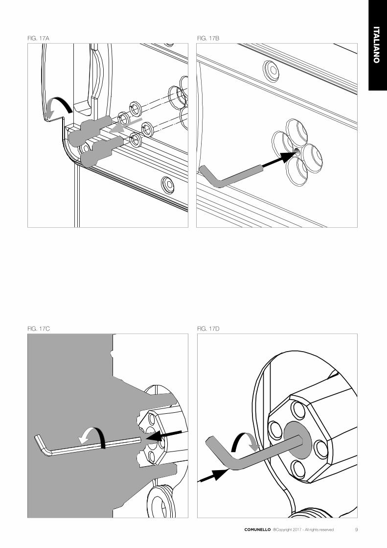
• Rimuovere le 4 viti di fissaggio con le rispettive randelle spaccate (FIG. 17A).
• Inserire la brugola da 5mm nell’appostito foro (FIG. 17B).• Svitare la vite per aiutare la rimozione della base del TABLET (FIG. 17C).• Riavvitare la vite all'albero del motore (FIG. 17D).
6 PREDISPOSIZIONE AI COLLEGAMENTI ELETTRICI
• Togliere la copertura frontale mediante l’utilizzo della chiave in dotazione (FIG. 4)
• Portare i fili elettrici alla scheda elettronica.
7 COLLAUDO
Per il collaudo di BORDER eseguire la seguente sequenza di operazioni:• Verificare che sia stato rispettato rigorosamente tutto quanto previsto nel
presente manuale ed in particolare nel capitolo 1 “Avvertenze generali”;• Utilizzando i dispositivi di comando o arresto previsti (selettore a
chiave, pulsanti di comando o trasmettitori radio), effettuare delle prove di apertura, chiusura ed arresto della barriera e verificare che il comportamento corrisponda a quanto previsto.
• Verificare uno ad uno il corretto funzionamento di tutti i dispositivi di sicurezza presenti nell’impianto (fotocellule, bordi sensibili, arresto di emergenza, ecc.).
8 MANUTENZIONE DEL PRODOTTO
La manutenzione deve essere effettuata regolarmente da parte di personale qualificato secondo quanto previsto dalle leggi e normative vigenti. Per BORDER è necessaria una manutenzione programmata al massimo entro 6 mesi dalla precedente manutenzione.• Scollegare qualsiasi fonte di alimentazione dal motore• Verificare e sostituire tutte le parti di movimento usurate• Verificare lo stato di deterioramento di tutte le parti dell’automazione.
9 RICAMBI
È possibile acquistare dei particolari di ricambio, in caso di tale necessità contattare l’assistenza tecnica.
10 SMALTIMENTO
Al termine della vita dell’automazione, assicuratevi che lo smantellamento sia eseguito da personale qualificato e che i materiali vengano riciclati o smaltiti secondo le norme valide a livello locale.
11 SCHEDA ELETTRONICA
11.1 AVVERTENZE
• La centrale non presenta nessun tipo di dispositivo di sezionamento della linea elettrica 230 Vac, sarà quindi cura dell’installatore prevedere nell’impianto un dispositivo di sezionamento. È necessario installare un interruttore omnipolare con categoria III di sovratensione e apertura ai contatti di almeno 3mm. Esso deve essere posizionato in modo da essere protetto contro le richiusure accidentali secondo quanto previsto al punto 5.2.9 della EN 12453. Il cablaggio dei vari
componenti elettrici esterni alla centralina deve essere effettuato secondo quanto prescritto dalla normativa EN 60204-1 e dalle modifiche a questa apportata dal punto 5.2.7 della EN 12453.
I cavi di alimentazione possono avere un diametro massimo di 14 mm; il fissaggio dei cavi di alimentazione e di collegamento, deve essere garantito tramite l’assemblaggio di pressacavi fornibili “optional”.
• Utilizzare in fase di installazione esclusivamente cavi in doppio isolamento (cavi con guaina) sia per i collegamenti a tensione di rete (230V) che per i collegamenti in bassissima tensione di sicurezza SELV. Utilizzare esclusivamente canalette in plastica, distinte per i cablaggi in bassa tensione (230V) e per i cablaggi in bassissima tensione di sicurezza (SELV).
• I conduttori a bassissima tensione di sicurezza devono essere fisicamente separati (almeno 4 mm in aria) dai conduttori a tensione di rete, oppure devono essere adeguatamente isolati con isolamento supplementare avente spessore di almeno 1 mm.
• Prevedere a monte della rete di alimentazione dell’automazione un dispositivo che assicuri la disconnessione completa omnipolare della rete, con una distanza di apertura dei contatti in ciascun polo di almeno 3mm. Tali dispositivi di disconnessione devono essere previsti nella rete di alimentazione conformemente alle regole di installazione e devono essere direttamente collegati ai morsetti di alimentazione.
• Per i cavi di alimentazione si raccomanda di utilizzare cavi flessibili sotto guaina isolante in policloroprene di tipo armonizzato (FG16) con sezione minima dei conduttori pari a 1,5mm2.
• Fare attenzione, in fase di foratura dell’ involucro esterno per far passare i cavi di alimentazione e di collegamento, e di assemblaggio dei pressacavi, ad installare il tutto in modo da mantenere il più possibile inalterate le caratteristiche di grado IP della scatola. Prestare inoltre attenzione a fissare i cavi in modo che siano ancorati in modo stabile.
• L’involucro nella parte posteriore è provvisto di opportune predisposizioni per fissaggio a muro (predisposizione per fori per fissaggio mediante tasselli o fori per fissaggio mediante viti). Prevedere e implementare tutti gli accorgimenti per una installazione che non alteri il grado IP.
• L’eventuale montaggio di una pulsantiera

15COMUNELLO ®Copyright 2017 - All rights reserved
ITALIA
NO
per il comando manuale deve essere fatto posizionando la pulsantiera in modo che l’utente non venga a trovarsi in posizione pericolosa.
• Il motoriduttore usato per muovere la barriera deve essere conforme a quanto prescritto al punto 5.2.7 della EN 12453.
• L’uscita FOTO+ è necessariamente dedicata all’alimentazione delle fotocellule, non è consentito l’utilizzo per altre applicazioni.
• La centrale ad ogni ciclo di manovra può effettuare il test di funzionamento delle fotocellule, garantendo una protezione al guasto dei dispositivi antischiacciamento di Categoria 2 secondo quanto prescritto al punto 5.1.1.6. della EN 12453. Quindi se i dispositivi di sicurezza non vengono connessi e/o non sono funzionanti la centrale non è abilitata al funzionamento.
• L’apparecchio può essere utilizzato da bambini di età non inferiore a 8 anni e da persone con ridotte capacità fisiche, sensoriali o mentali, o prive di esperienza o della necessaria conoscenza, purché sotto sorveglianza oppure dopo che le stesse abbiano ricevuto istruzioni relative all’uso sicuro dell’apparecchio e alla comprensione dei pericoli ad esso inerenti. I bambini non devono giocare con l’apparecchio. La pulizia e la manutenzione destinata ad essere effettuata dall’utilizzatore non deve essere effettuata da bambini senza sorveglianza.
Per un corretto funzionamento della parte radio ricevente, in caso di utilizzo di due o più centrali, si consiglia l’installazione ad una distanza di almeno 3 metri l’una dall’altra.
ATTENZIONE:Tutte le operazioni che richiedono l’apertura dell’involucro (collegamento cavi, programmazione, ecc.) devono essere eseguite in fase di installazione e manutenzione da personale esperto.
IMPORTANTE PER L’UTENTE• Il dispositivo non deve essere utilizzato da bambini
o da persone con ridotte capacità psico-fisiche, almeno che non siano supervisionati o istruiti sul funzionamento e le modalità di utilizzo.
• Non consentire ai bambini di giocare con il dispositivo e tenere lontano dalla loro portata i radiocomandi.
• ATTENZIONE! conservare questo manuale d’istruzioni e rispettare le importanti prescrizioni di sicurezza in esso contenute. Il non rispetto
delle prescrizioni potrebbe provocare danni e gravi incidenti.
Esaminare frequentemente l’impianto per rilevare eventuali segni di danneggiamento. Non utilizzare il dispositivo se è necessario un intervento di riparazione.
11.2 CARATTERISTICHE TECNICHE• Ingresso Batteria d’emergenza: 24 V 7A/h min.• Uscita lampeggiante: 24 V 4 W max.• Uscite motori: 24V 1 x 50 W max.• Alimentazione fotocellule: 24 V 5 W max. • Temperatura d’esercizio: -10°C ÷ + 55°C• Ricevitore radio: 433 MHz• Trasmettitori op.: 18 Bit o Rolling Code• Codici TX max. in memoria: 120 (CODE o CODE PED)• Dimensioni scheda: 100x105 mm.
11.3 COLLEGAMENTI ELETTRICI
CN1:BATT+24V: Ingresso +24V Batteria d’emergenzaBATT-24V: Ingresso – 24V Batteria d’emergenza.LAMP+24V: Uscita + 24V Lampeggiante.LAMP-24V: Uscita – 24V Lampeggiante.MOT1+: Uscita + Motore 1.MOT1-: Uscita - Motore 1.CN2:STOP: Ingresso Blocco (NC).GND: Ingresso GND comune.FOTO+: Controllo e Alimentazione Fotocellule (24V 5W).GND: Controllo e Alimentazione Fotocellule (GND).FCC: Ingresso Finecorsa Chiusura Motore (NC).GND: Ingresso GND comuneFCA: Ingresso Finecorsa Apertura Motore (NC).DS1: Ingresso Dispositivo Sicurezza (NC).GND: Ingresso GND comunePP: Ingresso Pulsante P/P comando apre-chiude (NA).ANT-: Ingresso Massa Antenna.ANT+: Ingresso Polo caldo Antenna.
• Collegamento del cavo di alimentazione di tipo Y.COLLEGAMENTI DEL TRASFORMATORECN4:1: Ingresso avvolgimento Primario Trasformatore 230 Vac.2: Ingresso avvolgimento Primario Trasformatore 230Vac.CN5:1: Uscita SEC Trasformatore 21.7 V 7.5 A tensioni a vuoto2: Uscita SEC Trasformatore 21.7 V 7.5 A tensioni a vuoto
11.4 CARATTERISTICHE FUNZIONALI
FUNZIONAMENTO:Utilizzando sia il radiocomando che la pulsantiera in bassa tensione per l’azionamento della barriera, si otterrà il seguente funzionamento:il primo impulso comanda l’apertura fino allo scadere del tempo motore o al raggiungimento del fine corsa d’apertura, il secondo impulso comanda la chiusura della barriera; se si invia un impulso durante la fase di Apertura, la centrale Ignora il comando, se si invia un impulso durante la fase di Chiusura la centrale effettua l’inversione del moto.
CHIUSURA AUTOMATICA:La centrale permette di richiudere la barriera in modo automatico senza l’invio di comandi supplementari.La scelta di questo funzionamento è descritta nel modo di programmazione del Tempo di pausa.
FOTOCELLULE:La centrale permette l’alimentazione ed il collegamento di Fotocellule in accordo alla direttiva EN 12453. • Ingresso DS1(NC) L’intervento delle fotocellule nella fase di apertura non viene considerato,
nella fase di chiusura provoca l’inversione del moto. NOTA: Per consentire un funzionamento rispondente alla Categoria

16 COMUNELLO ®Copyright 2017 - All rights reserved
2 di EN 13849-1 viene eseguito prima di ogni manovra un test delle fotocellule. Per poter eseguire questo test è indispensabile alimentare la trasmittente di ogni coppia di fotocellule mediante l’apposita uscita di “Controllo e Alimentazione Fotocellule” ( uscite 1 e 2 della morsettiera CN2). Solo se viene superato il test la centrale avvia la manovra: in caso contrario la centrale non consente nessun movimento e ad ogni comando il lampeggio di tutti i led di programmazione segnala la situazione di allarme.
FINECORSA APERTURA E CHIUSURA:La centrale permette il collegamento di Finecorsa Apertura e Chiusura (NC). L’intervento nelle rispettive fasi di funzionamento provoca l’inizio della fase di rallentamento.
REGOLAZIONE VELOCITA' MOTORE DURANTE CICLO “NORMALE”:La centrale elettronica è dotata di un trimmer “SPEED” per la regolazione della Velocità Massima Motore durante il ciclo normale.
REGOLAZIONE VELOCITA’ MOTORE DURANTE CICLO “RALLENTATO”:La centrale elettronica è dotata di un menù “SLOWING” per la regolazione della Velocità Motore durante il ciclo rallentato.
RILEVAMENTO OSTACOLO:La centrale elettronica è dotata di un trimmer “SENS” per la regolazione della Forza di contrasto necessaria alla rilevazione dell’ostacolo, completamente gestita dal microprocessore.• Senso orario: aumento sensibilità rilevamento.• Senso antiorario: diminuzione sensibilità rilevamento.In chiusura si ha un’inversione del moto, mentre in apertura si ha un blocco della fase di chiusura.L’intervento ostacolo viene segnalato dal breve lampeggio dei LED nel menù principale.
LAMPEGGIATORE:La centrale è dotata di un’uscita per la gestione di un lampeggiatore 24V 4W max. Il suo funzionamento è condizionato dal movimento del motore.
FUNZIONAMENTO CON TIMER:La centrale permette di collegare al posto del pulsante di comando apre – chiude un timer.Esempio: ore 08.00 il timer chiude il contatto e la centrale comanda l’apertura, ore 18.00 il timer apre il contatto e la centrale comanda la chiusura. Durante l’intervallo 08.00 – 18.00 al termine della fase di apertura la centrale disabilita il lampeggiante, la chiusura automatica e i radiocomandi.
BATTERIA TAMPONE:La centrale è dotata di caricabatteria incorporato a 24V . La centrale permette il collegamento di una batteria tampone di capacità Max 7 Ah, che consentirà di effettuare in modalità di emergenza alcune manovre complete a velocità ridotta. Il Lampeggiatore, se presente, in assenza della tensione di rete funzionerà solamente per i primi 4 secondi della manovra.
11.5 PROGRAMMAZIONE
Tasto SEL: seleziona il tipo di funzione da memorizzare, la selezione è indicata dal lampeggio del Led.Premendo più volte il tasto, è possibile posizionarsi sulla funzione desiderata. La selezione resta attiva per 10 secondi, visualizzata dal Led lampeggiante, se trascorsi, la centrale ritorna allo stato originario.Tasto SET: effettua la programmazione dell'informazione secondo il tipo di funzione prescelta con il tasto SEL.IMPORTANTE: La funzione del tasto SET può anche essere sostituita dal radiocomando se precedentemente programmato (led CODE acceso).
MENÙ PRINCIPALELa centrale è fornita dal costruttore con la possibilità di selezionare alcune funzioni importanti.
LED SPENTO LED ACCESO
L1 CODE TX Nessun codice Codice inserito
L2 MOTOR TIME T.prog. di fabbrica Tempo programmato
L3 PAUSE TIME Senza ch. automatica Con ch. automatica
L4 FORCE OPEN Massima Med – Min reg. da speed
L5 FORCE CLOSE Massima Med – Min reg. da speed
L6 SLOWING OPEN Massima Med – Min reg. da Slowing
L7 SLOWING CLOSE Massima Med- Min reg. da Slowing
LEV MENÙ ON
1. CODE (Codice del radiocomando):La centrale permette di memorizzare fino a 120 radiocomandi aventi codice diverso fra loro di tipo fisso o rolling code.Programmazione:La programmazione del codice di trasmissione è eseguita nel seguente modo: posizionarsi con il tasto SEL sul lampeggio del LED L1, inviare il codice prescelto con il radiocomando desiderato entro 10 secondi, il LED L1 resterà acceso permanentemente indicando che la programmazione sarà completata. Dopo ogni inserimento corretto di un codice radio, la centrale rimane in attesa di apprendere un successivo codice per altri 10 secondi.Nel caso che tutti i 120 codici siano stati memorizzati, ripetendo l’operazione di programmazione, tutti i LED di programmazione inizieranno a lampeggiare segnalando che non sono possibili ulteriori memorizzazioni.Reset dei Radiocomandi:Per eseguire la cancellazione di tutti i radiocomandi precedentemente memorizzati nel ricevitore, posizionarsi con SEL sul LED L1, premere e tener premuto SET per tempo > 5 s. Alla fine il led si spegnerà per 2 sec e la procedura è completata. Regola del primo Radiocomando memorizzato: Nella programmazione dei radiocomandi vige la seguente regola: se il primo radiocomando ad essere memorizzato è un radiocomando di tipo rolling code il ricevitore accetterà poi solo radiocomandi rolling code, garantendo così una maggiore sicurezza antintrusione; se invece il primo radiocomando ad essere memorizzato è un radiocomando a codice fisso il ricevitore accetterà poi sia radiocomandi a codice fisso che radiocomandi rolling code.ATTENZIONE: Ogni volta che si effettua un reset dei radiocomandi nel ricevitore verranno cancellati tutti i Radiocomandi memorizzati e cancellata anche la regola del primo radiocomando. Dopo ogni radiocomando correttamente memorizzato la centrale attende per max 10 secondi l’invio di un ulteriore codice radio. Premere SEL per terminare la procedura senza attendere i 10 secondi.
2. MOTOR TIME (Programmazione tempo di lavoro della barriera):La programmazione deve essere effettuata a barriera chiusa nel seguente modo: posizionarsi con il tasto SEL sul lampeggio del LED L2 e poi premere per un istante il tasto SET, il Motore inizierà ciclo di Apertura; in corrispondenza del punto iniziale desiderato di rallentamento premere nuovamente il tasto SET: il LED L2 inizierà a lampeggiare più lentamente e il Motore effettuerà il rallentamento; al raggiungimento della posizione premere il tasto SET per concludere il ciclo di Apertura. Conclusa la programmazione del tempo ciclo di Apertura, il Motore riparte subito in Chiusura: ripetere le operazioni viste sopra, per la fase di Chiusura. ATTENZIONE: Le fasi di rallentamento sono pilotate dai finecorsa.
3. PAUSE TIME (Programmazione tempo chiusura aut. 4 min. max.):La centrale è fornita dal costruttore senza chiusura automatica. Se si desidera abilitare la chiusura automatica, procedere nel seguente modo: posizionarsi con il tasto SEL sul lampeggio del LED L3 e premere per un istante il tasto SET, attendere poi per un tempo uguale a quello desiderato; premere nuovamente per un istante il tasto SET, nello stesso momento si determinerà la memorizzazione del tempo di chiusura automatica e il LED L3 sarà acceso fisso. Se si desidera ripristinare la condizione iniziale (senza chiusura automatica), posizionarsi sul lampeggio del LED L3 poi premere consecutivamente per 2 volte il tasto SET in un intervallo di tempo di 2 secondi. Il Led si spegnerà e l’operazione sarà conclusa.
4. FORCE OPEN (Selezione profilo Velocità nel ciclo Normale di Apertura):
La centrale permette di definire diversi profili Velocità motore durante il ciclo di funzionamento Normale in fase di Apertura. Nella configurazione fornita dal costruttore Velocità del motore in fase di Apertura è definita al Massimo “MAX” (ovvero uguale alla regolazione impostata tramite il trimmer SPEED, LED L4 spento), se si desidera modificare il profilo ad un valore Medio “MED” procedere nel seguente modo: posizionarsi con il tasto SEL sul lampeggio del LED L4 poi premere il tasto SET, nello stesso istante il LED L4 si accenderà permanentemente e la programmazione sarà conclusa. Se si desidera modificare il profilo ad un valore Minimo “MIN” ripetere l’operazione sopra descritta, premendo il tasto SEL due volte (ottenendo il lampeggio veloce del LED L4) anziché una volta. Ripetere l’operazione se si desidera ripristinare la configurazione iniziale.
5. FORCE CLOSE (Selezione profilo Velocità nel ciclo Normale di Chiusura):
La centrale permette di definire diversi profili Velocità motore durante il ciclo di funzionamento Normale in fase di Chiusura. Nella configurazione fornita dal costruttore Velocità del motore in fase di Chiusura è definita al Massimo

17COMUNELLO ®Copyright 2017 - All rights reserved
ITALIA
NO
“MAX” (ovvero uguale alla regolazione impostata tramite il trimmer SPEED, LED L5 spento), se si desidera modificare il profilo ad un valore Medio “MED” procedere nel seguente modo: posizionarsi con il tasto SEL sul lampeggio del LED L5 poi premere il tasto SET, nello stesso istante il LED L5 si accenderà permanentemente e la programmazione sarà conclusa. Se si desidera modificare il profilo ad un valore Minimo “MIN”ripetere l’operazione sopra descritta, premendo il tasto SEL due volte (ottenendo il lampeggio veloce del LED L5) anziché una volta. Ripetere l’operazione se si desidera ripristinare la configurazione iniziale.
6. SLOWING OPEN (Selezione profilo Velocità nel ciclo Rallentato di Apertura):La centrale permette di definire diversi profili Velocità motore durante il ciclo di funzionamento Rallentato in fase di Apertura. Nella configurazione fornita dal costruttore Velocità del motore in fase di Apertura Rallentata è definita al Massimo “MAX” (ovvero uguale alla regolazione impostata tramite il menù SLOWING, LED L6 spento), se si desidera modificare il profilo ad un valore Medio “MED” procedere nel seguente modo: posizionarsi con il tasto SEL sul lampeggio del LED L6 poi premere il tasto SET, nello stesso istante il LED L6 si accenderà permanentemente e la programmazione sarà conclusa. Se si desidera modificare il profilo ad un valore Minimo “MIN” ripetere l’operazione sopra descritta, premendo il tasto SEL due volte (ottenendo il lampeggio veloce del LED L6) anziché una volta. Ripetere l’operazione se si desidera ripristinare la configurazione iniziale.
7. SLOWING CLOSE (Selezione profilo Velocità nel ciclo Rallentato di Chiusura):
La centrale permette di definire diversi profili Velocità motore durante il ciclo di funzionamento Rallentato in fase di Chiusura. Nella configurazione fornita dal costruttore Velocità del motore in fase di Chiusura Rallentata è definita al Massimo “MAX” (ovvero uguale alla regolazione impostata tramite il menù SLOWING, LED L7 spento), se si desidera modificare il profilo ad un valore Medio “MED” procedere nel seguente modo: posizionarsi con il tasto SEL sul lampeggio del LED L7 poi premere il tasto SET, nello stesso istante il LED L7 si accenderà permanentemente e la programmazione sarà conclusa. Se si desidera modificare il profilo ad un valore Minimo “MIN” ripetere l’operazione sopra descritta, premendo il tasto SEL due volte (ottenendo il lampeggio veloce del LED L7) anziché una volta. Ripetere l’operazione se si desidera ripristinare la configurazione iniziale.
MENÙ ESTESO 1La centrale è fornita dal costruttore con la possibilità di selezione diretta solamente delle funzioni del menù principale.Se si desidera abilitare le funzioni descritte nel Menù esteso 1, procedere nel seguente modo: posizionarsi sul lampeggio del LED LEV e premere 1 volta SET. Il led inizierà a lampeggiare in modo alternato 1 0 1 0 1 0. In questo modo si avranno 30 secondi di tempo per selezionare le funzioni del Menù Esteso 1 mediante l’uso dei tasti SEL e SET; trascorsi ulteriori 30 secondi la centrale ritorna al menù principale.
LED SPENTO LED ACCESO
L1 PROG. A DISTANZA OFF ON
L2 DIR. APERTURA OFF ON
L3 PROG. AUTOMATICA OFF ON
L4 FOTO TEST OFF ON
L5 DS1 IN APRE OFF ON
L6 NON USARE NON USARE NON USARE
L7 NON USARE NON USARE NON USARE
LEV MENÙ 1 LAMPEGGIO
1. PROGRAMMAZIONE RADIOCOMANDO A DISTANZA:La centrale consente la programmazione del codice di trasmissione, senza intervenire direttamente sul tasto SEL della centrale, ma eseguendo l’operazione a distanza.La programmazione del Radiocomando a distanza, si esegue nel seguente modo: inviare in modo continuo per un tempo maggiore a 10 secondi il codice di un radiocomando in precedenza memorizzato, allo stesso tempo la centrale entra in modo programmazione come sopra descritto per il LED L1 nel menù principale. Per abilitare la funzione di programmazione a distanza procedere nel seguente modo: assicurarsi di aver abilitato il Menù Esteso 1 (lampeggio alternato 1 0 1 0 1 0 del LED LEV)), posizionarsi con il tasto SEL sul lampeggio del LED L1 e poi premere il tasto SET: il LED L1 si accenderà permanentemente e la programmazione sarà conclusa. Ripetere l’operazione se si desidera ripristinare la configurazione iniziale.
2. DIREZIONE DI APERTURA (DIR):
La centrale nella configurazione di default presenta la logica di “ASTA A SINISTRA”(Fig.10B); se occorre abilitare la logica di “ASTA A DESTRA” (Fig. 10A), procedere nel seguente modo: posizionarsi con il tasto SELECT sul lampeggio del LED L1 e premere il tasto SET: il LED L1 si accenderà permanentemente e la programmazione sarà completata. Ripetere l’operazione se si desidera ripristinare la configurazione precedente.ATTENZIONE: se è necessario invertire la direzione d’apertura è necessario invertire i cablaggi dei FCA e FCC.
3. PROGRAMMAZIONE AUTOMATICA:La centrale permette di effettuare una Programmazione Automatica (SEMPLIFICATA) nel seguente modo: assicurarsi di aver posizionato la Barriera aperta a 45° e di aver abilitato il Menù esteso 1 (evidenziando il lampeggio 1 0 1 0 1 del led nr. 8), posizionarsi con il tasto SEL sul lampeggio del LED NR3; premendo il tasto SET, la centrale completa la fase di Auto programmazione eseguendo un'apertura e chiusura completa.Premere SET per confermare. Durante la Programmazione Automatica è possibile usare il tasto SET, posto sulla centrale, interrompere la procedura in caso di necessità.
4. FOTOTEST (Test fotocellule):La centrale è fornita dal costruttore con il test delle fotocellule disabilitato. Se si desidera abilitare tale test procedere nel seguente modo: assicurarsi di aver abilitato il Menù Esteso 1 (evidenziato dal lampeggio 1 0 1 0 1 del LED LEV), posizionarsi con il tasto SEL sul lampeggio del LED L4), poi premere il tasto SET, il LED L4 si accenderà permanentemente e la programmazione sarà conclusa. Ripetere l’operazione se si desidera ripristinare la configurazione precedente.
5. DS1 IN APRE:La centrale consente di modificare il funzionamento dell’ingresso DS1. Se si desidera che DS 1 intervenga anche in apertura (arresto momentaneo, una volta liberato la centrale riprende il moto in apertura), procedere nel seguente modo: assicurarsi di aver abilitato il Menù Esteso 2 posizionarsi con il tasto SEL sul lampeggio del LED L3 e poi premere il tasto SET: il LED L3 si accenderà permanentemente e la programmazione sarà conclusa.Ripetere l’operazione se si desidera ripristinare la configurazione iniziale.
6. NOT USED
7. NOT USED
MENÙ ESTESO 2La centrale è fornita dal costruttore con la possibilità di selezione diretta solamente delle funzioni del menù principale.Se si desidera abilitare le funzioni descritte nel Menù esteso 2, procedere nel seguente modo: posizionarsi sul lampeggio del LED LEV e premere 2 volta SET. Il led inizierà a lampeggiare in modo alternato 1 1 0 1 1 0. In questo modo si avranno 30 secondi di tempo per selezionare le funzioni del Menù Esteso 2 mediante l’uso dei tasti SEL e SET; trascorsi ulteriori 30 secondi la centrale ritorna al menù principale.
LED SPENTO LED ACCESO
L1 NON USARE NON USARE NON USARE
L2 CONTR.USCITA LAMP. LAMPEGGIANTE FISSA
L3 CHIUDI SEMPRE OFF ON
L4 FOLLOW ME OFF ON
L5 PRELAMPEGGIO OFF ON
L6 NON USARE NON USARE NON USARE
L7 NON USARE NON USARE NON USARE
LEV MENÙ 2 LAMPEGGI
1. NOT USED
2. CONTROLLO USCITA LAMPEGGIANTE 24V 4W MAX:La centrale è fornita dal costruttore l’uscita per il collegamento di un Lampeggiante 24V di tipo intermittente (0,5 sec ON – 0,5 sec OFF). Se si desidera abilitare il funzionamento di tipo fisso, procedere nel seguente modo: assicurarsi di aver abilitato il Menù Esteso 2 (evidenziato dal lampeggio 1 1 0 1 1 0 1 0 del LED LEV), posizionarsi con il tasto SEL sul lampeggio del LED L2 e poi premere il tasto SET: il LED L2 si accenderà permanentemente e la programmazione sarà conclusa. Ripetere l’operazione se si desidera ripristinare la configurazione precedente.
3. CHIUDI SEMPRE:

18 COMUNELLO ®Copyright 2017 - All rights reserved
La centrale permette di impostare il funzionamento “Chiudi Sempre”: tale funzione, programmabile solo se è già stato programmato un Tempo di Pausa, interviene dopo una mancanza di alimentazione; se viene rilevato che la barriera è aperta si avvia automaticamente una manovra di chiusura preceduta da 5s. di prelampeggio. Se si desidera tale modalità di funzionamento procedere nel seguente modo: assicurarsi di aver abilitato il Menù Esteso 2 (evidenziato dal lampeggio 1 1 0 1 1 0 del LED LEV), posizionarsi con il tasto SEL sul lampeggio del LED L3 e poi premere il tasto SET: il LED L3 si accenderà permanentemente e l’operazione sarà conclusa. Ripetere l’operazione se si desidera ripristinare la configurazione precedente.
4. FOLLOW ME:La centrale è permette di impostare il funzionamento “Follow me”: tale funzione, programmabile solo se è già stato programmato un Tempo di Pausa, prevede di ridurre il tempo di Pausa a 5 sec. dopo il disimpegno della fotocellula DS1, ossia il serramento si richiude 5 sec. dopo che l’utilizzatore è transitato.Per attivare tale funzione procedere nel seguente modo: assicurarsi di aver abilitato il Menù Esteso 2 (evidenziato dal lampeggio 1 1 0 1 1 0 del LED LEV), posizionarsi con il tasto SEL sul lampeggio del LED L4 e poi premere il tasto SET: il LED L4 si accenderà permanentemente e la programmazione sarà conclusa. Ripetere l’operazione se si desidera ripristinare la configurazione precedente.
5. PRELAMPEGGIO:La centrale è fornita dal costruttore con la funzione Prelampeggio disabilitata. Se si desidera abilitare la funzione Prelampeggio, procedere nel seguente modo: assicurarsi di aver abilitato il Menù Esteso 2 (evidenziato dal lampeggio 1 1 0 1 1 0 1 0 del LED LEV), posizionarsi con il tasto SEL sul lampeggio del LED L5 e poi premere il tasto SET: il LED L5 si accenderà permanentemente e la programmazione sarà conclusa; in questo modo l’uscita lampeggiatore si attiverà sempre 3 secondi prima che l’automazione dia inizio a qualsiasi movimento. Ripetere l’operazione se si desidera ripristinare la configurazione iniziale.
6. NOT USED
7. NOT USED
MENÙ ESTESO 3La centrale è fornita dal costruttore con la possibilità di selezione diretta solamente delle funzioni del menù principale.Se si desidera abilitare le funzioni descritte nel Menù Esteso 3, procedere nel seguente modo: posizionarsi sul lampeggio del LED LEV e premere 3 volte SET. Il led inizierà a lampeggiare in modo alternato 1 1 1 0 1 1 1 0 1 1 1 0. in questo modo si avranno 30 secondi di tempo per selezionare le funzioni del Menù Esteso 3 mediante l’uso dei tasti SEL e SET, poi dopo ulteriori 30 secondi la centrale ritorna al menù principale.
MENÙ ESTESO 3
livello LED ACCESO
L1 1 LED 1
L2 2 LED 1 +LED 2
L3 3 LED 1 +LED 2 +LED 3
L4 4 LED 1 + LED 2 +LED 3 +LED 4
L5 5 LED 1 + LED 2 +LED 3 +LED 4 +LED 5
L6 6 LED 1 + LED 2 +LED 3 +LED 4 +LED 5 + LED 6
L7 7 LED 1 + LED 2 +LED 3 +LED 4 +LED 5 + LED 6 + LED 7
LEV Menù 3 Lampeggi
REGOLAZIONE VELOCITA' IN RALLENTAMENTO:La centrale consente la programmazione della velocità del motore durante la fase di rallentamento.È possibile scegliere tra 7 diversi livelli di potenza in questo modo: assicurarsi di aver abilitato il Menù Esteso 3, ad ogni combinazione di led accesi corrisponde un livello secondo la tabella riportata sopra; in pratica a partire dal led più in basso (LED L1) e andando verso l’alto ogni led corrisponde ad un livello di potenza superiore. Tramite il tasto SEL è possibile scorrere tra i diversi livelli di potenza; per ogni livello di potenza selezionato, il rispettivo led più in alto lampeggia (ad esempio se è selezionato il livello 4, i LED L1 + LED L2 + LED L3 sono accesi fissi, mentre il LED L4 lampeggia); premere SET per confermare.
Nella configurazione di fabbrica è selezionato il livello 3.
12 RESET
Nel caso sia opportuno ripristinare la centrale alla configurazione di fabbrica, premere il tasto SEL e SET in contemporanea, allo stesso tempo si otterrà l’accensione contemporanea di tutti i led ROSSI di segnalazione e subito dopo lo spegnimento.
ATTENZIONE: Quando la centrale viene alimentata (reset power on), viene visualizzata la versione FW con l'accensione breve di un numero fisso di LED nel menù principale (es: primi 2 LED accesi fissi per 0,5sec = FW rev.02). Questa informazione può essere utile per il servizio di assistenza tecnica.
ATTENZIONE: il ripristino della configurazione di fabbrica non comprende la cancellazione di tutti i Radiocomandi precedentemente memorizzati e la regola del primo radiocomando.
13 DIAGNOSTICA
Test Fotocellula:La centrale è predisposta per la connessione di dispositivi di sicurezza che rispettano il punto 5.1.1.6 della normativa EN 12453. Ad ogni ciclo di manovra viene effettuato il test di funzionamento della fotocellula collegata. Nel caso di mancato collegamento e/o non funzionamento, la centrale non abilita il movimento del serramento ed evidenzia visivamente il fallimento del test effettuando il lampeggio contemporaneo di tutti i Led di segnalazione. Una volta ripristinato il corretto funzionamento della fotocellula, la centrale è pronta per il normale utilizzo. Ciò garantisce un monitoraggio contro i guasti conforme alla Categoria 2 della EN 954-1.
Test input comandi:In corrispondenza ad ogni ingresso di comando in bassa tensione, la centrale dispone di un LED di segnalazione, in modo tale da poter controllare rapidamente lo stato. Logica di funzionamento: LED acceso ingresso chiuso, LED spento ingresso aperto.
14 GARANZIA
a) La presente garanzia nei rapporti commerciali o in caso di vendita di beni per uso professionale è limitata alla riparazione o sostituzione del pezzo del Prodotto riconosciuto da FRATELLI COMUNELLO SPA quale difettoso mediante Prodotti rigenerati equivalenti (di seguito “Garanzia Convenzionale”), non risulta compresa nella garanzia il costo necessario per le attività di riparazione e sostituzione del materiale (a titolo esemplificativo costi di manodopera, noleggio materiali, etc).
b) E’ esclusa l’applicazione della disciplina dettata dagli articoli 1490-1495 del Codice Civile.
c) FRATELLI COMUNELLO SPA garantisce il funzionamento dei Prodotti nei limiti indicati al superiore punto sub 1. Salvo diverso accordo, la validità della Garanzia Convenzionale è di 24 (ventiquattro) mesi dalla data di produzione, rilevabile sui Prodotti. La Garanzia risulterà efficace e vincolante per COMUNELLO solo se il prodotto verrà correttamente montato e manutentato in conformità alle regole di installazione e di sicurezza indicate nella documentazione fornita da COMUNELLO o comunque rinvenibile sul sito http://www.comunello.com/it/corporate/condizioni-generali/
d) La garanzia non comprende: avarie o danni causati dal trasporto; avarie o danni causati da vizi dell’impianto elettrico presente presso l’acquirente il prodotto e/o da trascuratezza, negligenza, inadeguatezza, uso anomalo di tale impianto; avarie o danni dovuti a manomissioni poste in essere da parte di personale non autorizzato o conseguenti allo scorretto uso/installazione (a questo proposito, si consiglia una manutenzione del sistema almeno ogni sei mesi) o all’impiego di pezzi di ricambio non originali; difetti causati da agenti chimici e/o fenomeni atmosferici.La garanzia non comprende il costo per materiale di consumo, in ogni caso COMUNELLO matura il credito per l’intervento eseguito presso il cliente, laddove quest’ultimo si riveli inutile poiché non risultava operante la garanzia o perché il cliente aveva utilizzato il prodotto COMUNELLO in modo negligente, imprudente od imperito, tale per cui il corretto utilizzo del prodotto avrebbe potuto evitare l’installazione.
e) Termini attuativi: salvo diverso accordo, il diritto alla Garanzia Convenzionale si esercita esibendo copia del documento di acquisto
19COMUNELLO ®Copyright 2017 - All rights reserved
ITALIA
NO
(fattura fiscale) a COMUNELLO. Il Cliente deve denunciare il difetto a COMUNELLO entro il termine di decadenza di 30 (trenta) giorni dalla scoperta.L’azione deve essere esercitata entro il termine di prescrizione di 6 (sei) mesi dalla scoperta. I pezzi dei Prodotti per i quali viene richiesta l’attivazione della Garanzia Convenzionale devono essere spediti dal Cliente presso FRATELLI COMUNELLO SPA, Via Cassola 64, 36027 Rosà (VI) Italia.
f) Il Cliente non potrà richiedere il risarcimento di danni indiretti, mancati profitti, perdita di produzione ed in ogni caso non potrà pretendere a titolo di risarcimento somme superiori al valore dei componenti o dei Prodotti forniti. Tutte le spese per il trasporto dei Prodotti da riparare o riparati, anche se coperti dalla Garanzia Convenzionale, sono a carico del Cliente.
g) Nessun intervento esterno effettuato dal personale tecnico di COMUNELLO è coperto dalla Garanzia Convenzionale.
h) Modifiche specifiche delle condizioni della Garanzia Convenzionale qui descritte possono essere definite dalle parti nei propri contratti commerciali.
i) In caso di controversia legale di qualsiasi natura è applicabile il diritto italiano ed è competente il Foro di Vicenza.

20 COMUNELLO ®Copyright 2017 - All rights reserved
BORDER 400 / 600INSTALLATION AND USER’S MANUAL
EC DECLARATION OF COMFORMITY:
The undersigned Mr. Luca Comunello, representing the following manufacturer,
Fratelli COMUNELLO SpaVia Cassola 64, 36027 Rosà (VI) – Italy
DECLARES that the equipment described below:
Description: Electromechanical automation for barrier systemModel: BORDER 400 / 600
Is in compliance with the provisions set down in the following directives:
• 2014/30/EU (Directive EMCD) • 2011/65/EU (Directive RoHS)• 2006/42/CE (Directive MD)• 2014/53/EU (Directive RED)and that all the rules and/or technical specifications shown below have been applied:
EN61000-6-2:2005 + EN61000-6-3:2007EN61000-4-3:2006 + A1:2008 + IS1:2009 + A2:2010EN62233:2008ETSI EN 301 489-1 V.2.2.0ETSI EN 301 489-3 V.2.1.1EN60335-2-103 :2015 + EN60335-1 :2012
and the following amendments.
Rosà (VI) – Italia16-11-2017
and he also declares that it is not allowed to commission the device until the machinery where it will be incorporated or whose it will become a component will have been identified and will have been declared in compliance with the conditions of the 2006/42 EC Directive and with the national legislation that transpose it.
Mr. Luca Comunello Fratelli Comunello Legal Representative
Fratelli Comunello S.p.A.Company with certified Quality Management System
UNI EN ISO 9001:2015.

21COMUNELLO ®Copyright 2017 - All rights reserved
EN
GLIS
H
CONTENTS1 GENERAL PRESCRIPTIONS1.1 Safety prescriptions1.2 Installation prescriptions1.3 Operating prescriptions2 MODELS AND PRODUCT DESCRIPTION2.1 Description2.2 Typical installation3 PRODUCT TECHNICAL SPECIFICATIONS4 INSTALLATION 4.1 Preliminary checks 4.2 Operating limits 4.3 Preparatory work for installation 4.4 Installing the BORDER barrier system 4.4.1 Installation4.4.2 Limit stops adjustment 4.4.3 Manual release 4.4.4 Installation of the swing down support5 REMOVAL OF THE BAR SUPPORT6 PREPARATION FOR ELECTRICAL CONNECTIONS7 TESTING8 PRODUCT MAINTENANCE9 SPARE PARTS10 DISPOSAL OF THE PRODUCT11 ELECTRONIC CIRCUIT BOARD11.1 Prescriptions11.2 Technical characteristics11.3 Electrical connections11.4 Functional characteristics11.5 Programming12 Reset13 Diagnostics14 Warranty
1 GENERAL PRESCRIPTIONS
1.1 SAFETY PRESCRIPTIONSThis installation manual is addressed exclusively to professionally skilled personnel. Read all the instructions carefully before starting the installation procedures. Any operations that are not expressly set down in these instructions are to be considered prohibited; improper use may result in damage to the product and place persons and property at risk. The manufacturer declines all liability for failure to observe best technical practices in barrier system construction and for any possible deformations that may occur when using the product. Store this manual in a safe place for future reference. The design and construction of the devices fitted on the BORDER model as well as this manual are in full compliance with statutory legislation. In consideration of potential hazards that may arise during the installation and use of BORDER, also the installation procedures must be carried out in full compliance with the applicable laws, standards and regulations; specifically:
1.2 INSTALLATION PRESCRIPTIONS• Before starting the installation procedures
make sure you have any additional devices and materials that may be required to complete the
BORDER barrier system in consideration of the specific application.
• The automation system must not be used until the transit area has been made safe.
• Dispose of packaging materials in compliance with local regulations.
1.3 OPERATING PRESCRIPTIONS• No modifications can be made to any part of
the product unless specified in this manual. Unauthorized modifications of the product are likely to lead to malfunctions. The manufacturer declines all liability for damage caused by unauthorized modifications.
• The parts of the automation system must never be immersed in water or other liquids. During the installation procedures ensure that no solid objects or liquids penetrate inside the control unit or other open devices.
• If liquids penetrate any parts of the automation system, disconnect the electrical power supply immediately and consult technical service; the use of BORDER in such conditions may give rise to potentially hazardous situations.
• Keep all parts of the BORDER barrier system away from heat sources and open flames; exposure to heat or flames may damage the devices and cause faults, fire, or hazardous situations.
• When the system remains unused for a long time, remove the optional battery and store it in a dry place to avoid the risk of leakage of harmful substances.
• Any operations that require parts of the BORDER barrier system to be opened must be performed with the control unit and the electrical power supply disconnected; if the disconnect device is not clearly visible from where you are working, attach a warning notice to the effect: “WARNING - MAINTENANCE IN PROGRESS”.
• In the case of tripping of circuit breakers or blowing of fuses, find the fault and remedy it before resetting the circuit breaker or changing the fuse.
• If the fault cannot be remedied using the information given in this manual, consult technical service.
2 MODELS AND PRODUCTS DESCRIPTION
2.1 DESCRIPTION Sturdy and easy to install, the BORDER electromechanical barrier system is suitable for residential, public and industrial applications. Thanks to the on-board electronic control unit any type of barrier system function can

22 COMUNELLO ®Copyright 2017 - All rights reserved
be programmed.
2.2 TYPICAL INSTALLATION
DE C
B
B
A
KEYA BARRIER SYSTEM WITH INTERNAL CONTROL UNITB PHOTOCELLSC FLASHING LIGHTD KEY SELECTOR SWITCHE END REST
3 TECHNICAL SPECIFICATIONS
BORDER 400
Operator power supply 24 V
Maximum power consumption 100 W
Current input 4,5 A max
Torque 300 Nm
Duty cycle Intensive (15” ON - 45” OFF)
Protection rating IP 44
Insulation class I (1)
Working temperature from -20°C to + 50°C
Weight 65 Kg
4 INSTALLATION
4.1 PRELIMINARY CHECKSFor correct operation of the automation system, make sure:• all the accessories are suitably sized and properly maintained.• all the operating limits of the product can be complied with.• the minimum and maximum clearances shown in FIG. 1A.• all material used is in perfect condition and fit for purpose.• the selected installation site is compatible with the overall dimensions of
the product.• there are no hindrances that could obstruct the opening and closing
movements of the barrier arm.• the footing of the barrier system is able to provide stable anchorage of
the unit.• the space around the barrier system is sufficient to allow easy and safe
execution of manual barrier operations.• all devices to be installed are in a protected location so as to minimize
the risk of accidental impact.• If necessary, create a pedestrian entrance well clear of the operating
range of the barrier arm.
4.2 APPLICATION LIMITS
• Use a fixed end rest for arms more than 3 m long Before installing the operator check that its specifications are within theoperating limits shown in the chapter 3: “Product Technical Specifications”.
4.3 PREPARATORY WORK FOR INSTALLATION• Assemble counterplate and anchor bolts. Make sure to leave out about
30mm of the anchor bolts (FIG. 2A).• Embed counterplate and anchor bolts in concrete (FIG. 3A).• In the case of an existing concrete footing drill 4 holes for the screw
anchors as shown in FIG. 3B.
4.4 INSTALLING THE BORDER BARRIER SYSTEM
4.4.1 INSTALLATION:• Remove the front cover using the supplied key (FIG. 4)• Place the pedestal on the counterplate, routing the power and
accessories cables through the cable inlet hole. Secure the pedestal with the nuts and washers supplied (FIG. 5)
Arm assembly:• Insert the impact protection strip in the specific guides.NOTE: the protection strip will be 100 mm too long; push it until it is snug
against the barrier (Fig. 6A)• Secure the end cap to one end of the arm, as shown in FIG. 7A.Installing the arm:• Release the operator as described in heading 4.4.3• Fix the arm support to the protruding pivot at the rear of the frame.
Ensure it is in the “arm horizontal” position (FIG. 8A) and that the internal mechanism is in the position shown in FIG. 8B. Smear threadlocker on the 4 central screws.
• Insert the hole cover in the guides at the rear of the arm support (FIG. 8C).
• Make sure the arm is fully inserted into the support and then close the support with the designated screws (FIG. 8D).
Fitting the springs:The BORDER 400 barrier system is equipped with single spring mechanism, Depending on the accessories and on the lenght of the arm, the spring can be installed in the first or in the second hole of the spring stretcher tool. Please have a look at the following table:
BORDER 400 SPRING STRETCHER TOOL LENGTH (METERS)
21 1
2
2 211 3
2 m 3 m 4 m
BAR - 1-2 2BAR WITH BAR COVER KIT 1 1-2 2BAR WITH SWING DOWN SUPPORT 1 2 2BAR WITH SKIRT AND SWING DOWN SUPPORT 1 2 2
• When the barrier system is locked (heading 4.4.3), bring the arm to the vertical position, as shown in FIG. 9A.
• Secure the spring between the frame and the spring stretcher tool (FIG. 9B). The result is shown in FIG. 10A.If You wish to install the arm on the opposite part, then the configuration is shown in FIG. 10B.
• When installed, make sure the arm is counterbalanced by the spring as shown in figures FIG. 11A, FIG. 11B and FIG. 11C.
Spring pull adjustment:• With the operator released (heading 4.4.3), bring the arm manually to
approximately the mid-point of its excursion (45°) (FIG. 11A) and release it.If the rod tends to fall, it is necessary to act on the spring adjustment, turning it clockwise; if instead, the rod tends to rise, it is necessary to act on the spring by turning it counterclockwise, see FIG 11C.
• A time found the correct balancing rod, lock the system with the locknut in the spring mechanism (FIG 11C).
4.4.2 BORDER SWITCH ADJUSTMENT The BORDER barrier system is equipped with electromechanical limit switches. If actived, they can lower the arm speed when the arm has almost reached its final position:• If You wish to move the arm slow down further to the closing position,
loosen the bolt for max 2 rotations and then move the left the cam wheel counterclockwise, as shown in FIG. 12B.
• If You wish to move the arm slow down further to the opening position, loosen the bolt for max 2 rotations and then move the right cam wheel clockwise, as shown in FIG. 12C.
• Once You found the right positions for the cam wheels, You can fasten back the bolts.
In order to adjust the horizontal and vertinal position of the arm, proceed as follows:• If in the closed position the arm doesn't look parallel to the ground, adjust the
bolt, marked in FIG. 13A.

23COMUNELLO ®Copyright 2017 - All rights reserved
EN
GLIS
H
• If in the opening position the arm doesn't look vertical to the ground, adjust the bolt, marked in FIG. 13B.
• Once the arm is adjust, fasten back the bolts.
4.4.3 MANUAL RELEASETo release the operator, so that the barrier arm can be moved by hand, open up one of the two lateral hatch and turn the handles following the arrows, as shown in FIG. 14.
4.4.4 INSTALLATION OF THE SWING DOWN SUPPORT (FIG. 15):• If already installed remove the end plug from the arm.• Pull out the lower barrier bar cover and cut it in order to leave enough
room for the swing down support (FIG.16 A).• Insert the barrier bar cover and the end plug back. Don't secure the end
plug.• Place the swing down support in order to easily punch it. After that drill
without the swing down support (FIG. 16A).• After having inserted the drilled plate in the lower guide of the arm, secure
the swing down support to the drilled plate with the designated screws (FIG. 16B).
• Put back the arm end plug.
5 REMOVAL OF THE BAR SUPPORT
• Remove the 4 fixing screws with their respective grower washers (FIG. 17A).
• Insert the 5mm Allen key into the appropriate hole (FIG. 17B).• Unscrew the screw to help the removal of the bar support base (FIG.
17C).• Tighten the screw to the motor shaft (FIG. 17D).
6 PREPARATION FOR ELECTRICAL CONNECTIONS
• Remove the front cover using the supplied key (Fig.4)• Bring the wiring to the electronic circuit board.
7 TESTING
Perform the following sequence of operations to test the BORDER barrier system:• Check that all the prescriptions in this manual have been followed
scrupulously, with special attention to chapter 1 “General Prescriptions”;• Using the supplied control or stopping devices (key selector switch,
control pushbuttons or remotes), perform opening, closing and stopping tests and make sure the barrier responds correctly to the various commands.
• Check operation of all the system’s safety devices (photocells, safety edges, emergency stop, etc.), one by one.
8 PRODUCT MAINTENANCE
Maintenance must be carried out at regular intervals by qualified personnel in compliance with the provisions of statutory legislation and the regulations in force. BORDER undergo scheduled servicing at least once every 6 months.• Disconnect the operator from all power supplies• Check all the moving parts and renew any worn parts• Check all parts of the automation system for signs of deterioration
9 SPARE PARTS
Spare parts can be purchased by contacting technical service.
10 DISPOSAL
At the end of its useful life the automation system must be dismantled by qualified personnel and the materials must be recycled or disposed of in compliance with the local legislation in force.
11 ELECTRONIC CIRCUIT BOARD
11.1 PRESCRIPTIONS
• The control unit is not equipped with a device for disconnection of the 230 Vac power supply line. It is therefore the responsibility of the installer to fit a disconnection device in the electrical system. The disconnection device must be composed of a category III overvoltage all-pole circuit breaker and opening the contacts of at least 3mm. This device must be positioned in consideration of the need to be protected against inadvertent reconnection in compliance with the requirements of EN 12453 point 5.2.9. Wiring of the external electrical devices to the control unit must be carried out in compliance with the prescriptions of EN 60204-1 as amended by EN 12453 point 5.2.7. The maximum diameter of power feeding cables is 14 mm; fixing of power feeding and connection cables must be assured by fitting cable glands, which can be supplied as optionals.
• The power input cables must be of the standardized flexible type with polychloroprene sheath (FG16) having minimum conductor size of 1,5 mm2.
• During the installation operations, take care to use cable with double insulation only (sheathed cables) for both of mains voltage connections (230V) and extra-low voltage connections (SELV). Use exclusively plastic cable trays, separated for mains voltage wiring (230V) and extra-low voltage wiring (SELV).
• The extra low voltage conductors must be physically separated (at least 4 mm in air) from the mains voltage wires, or shall be adequately insulated with extra insulation with a thickness of at least 1 mm.
• Upstream of main supply, install a device that ensures the complete omnipolar disconnection (cut-off switch) of the power supply, with a contact opening gap of at least 3mm in each pole. These disconnecting devices shall be places in the power supply wiring in compliance with the installation standards and must be directly connected to the supply terminals.
• When drilling the outer case to insert the power and connection cables and when fitting the cable glands, take care to install all the parts in a manner that maintains the IP protection characteristics of the box unchanged as far as possible. Ensure the cables are fixed in a stable

24 COMUNELLO ®Copyright 2017 - All rights reserved
and secure manner.• The rear of the box is equipped with knockouts
for wall fixing (knockouts for fixing holes using anchor bolts or holes for fixing with screws). Take all the measures required to ensure the installation procedures do not affect the IP rating.
• If required, a pushbutton panel for manual control of the gate must be installed in a position such as to ensure the user is not placed in danger.
• The operator utilized to move the barrier must be in compliance with the prescriptions of EN 12453, point 5.2.7.
• Power Supply output D.S. must be used for photocells. Alternative uses of this output are not permitted.
• At each operating cycle, the control unit can test the photocells operation to ensure protection against failure of anti-crushing protective devices according to Category 2 in compliance with the prescriptions of EN 12453 point 5.1.1.6. It follows that if the safety devices are not connected or are faulty, operation of the control unit will be inhibited.
• The device can be used by children no older than 8 years old and people with reduced physical, sensory or mental capabilities, or lack of experience or without the required knowledge, but only under surveillance or after having received instructions about the safe use of the device and the hazards inherent in it. Children should not play with the device. Cleaning and maintenance should not be carried out by children without supervision.
For correct operation of the radio receiver section, when using two or more control units it is good practice to install them at a minimum distance of 3 metres from one another.
ATTENTION:All operations that require the control unit box to be opened (connection of cables, programming, etc.) must be carried out by expert personnel at the time of installation and maintenance. For all further operations that require the box to be re-opened.
IMPORTANT FOR THE USER• The device must not be use by children or people with reduced psychophysics abilities, or at
least in case they are supervised or educated on the operation and its use. • Do not allow the children to play with the device and keep them out from the remotes.• ATTENTION! preserve this manual of instructions and respect the important safety prescriptions in it contained. The non-observance of these prescriptions could provoke damages and serious accidents.Examine frequently the plant to notice possible signs of damage. Don't use the device if an intervention of reparation is necessary.
11.2 TECHNICAL CHARACTERISTICSBack-up Battery input: 24 V 7A/h min.Flashing light output: 24 V 4 W max.Operator outputs: 24V 1 x 50 W max.Photocells power supply: 24V 5 W max. Working temperature: -10°C ÷ + 55°CRadio receiver: 433 MhzTransmitters: 18 Bit or Rolling CodeMax TX codes stored in memory: 120 (CODE or PED CODE)Board dimensions: 100x105 mm.
11.3 ELECTRICAL CONNECTIONSCN1:BATT+24V: +24V Back-up Battery inputBATT-24V: –24V Back-up Battery input.LAMP+24V: +24V Flashing Light Output.LAMP-24V: –24V Flashing Light Output.MOT1+: Operator 1 + Output.MOT1-: Operator 1 – Output.CN2:STOP: Emergency stop input (NC)GND: Common GND inputFOTO+: Photocells Control and Power Supply (24V 5W).GND: Photocells Control and Power Supply (GND).FCC: Operator Closing Limit Switch Input (NC).GND: Common GND inputFCA: Operator Opening Limit Switch Input (NC).DS1: Safety Device Input (NC).GND: Common GND inputPP: Pedestrian Pushbutton open-close command input (NO).ANT-: Antenna Ground Input.ANT+: Antenna Hot pole input.
• Connection of the Y power cord.TRANSFORMER CONNECTIONSCN4:1: Transformer primary winding input 230 Vac.2: Transformer primary winding input 230 Vac.CN5:1: Transformer SEC output 21.7 V 7.5 A no-load voltage2: Transformer SEC output 21.7 V 7.5 A no-load voltage
11.4 FUNCTIONAL CHARACTERISTICSOPERATION:When either the remote or the low voltage pushbutton panel are used to control the barrier, operation is as follows:the first command opens the barrier until motor time elapses or the arm reaches its opening limit position; the second command closes the barrier; if another command is transmitted during the Opening movement, the control unit disregards the command; if a command is transmitted during the Closing movement the control unit reverses the movement direction.
AUTOMATIC CLOSING:The control unit can be set up to close the barrier automatically without sending any additional commands.Selection of this type of operation is described in Pause time programming mode.

25COMUNELLO ®Copyright 2017 - All rights reserved
EN
GLIS
H
EMERGENCY STOP INPUT:The control unit allows the connection of an emergency stop pushbutton (NC). Pressing this pushbutton irrespective of the current operating mode of the control unit will cause barrier movements to stop immediately. An additional barrier movement command will be valid, provided the emergency stop input is deactivated and, in any case, the control unit will perform the barrier opening cycle after preflashing for 5 seconds.
PHOTOCELLS:Photocells can be powered by and connected to the control unit in accordance with directive EN 12453.• Input DS1 (NC) Tripping of the photocells during opening is disregarded, while during
closing it causes reversal of the direction of movement.NOTES:To allow operation in compliance with EN 13849-1 Category 2 a
photocell test is performed before each movement. In order to perform this test it is essential to power the transmitter of each pair of photocells on the specific "Photocell Power and Control" output (outputs 1 and 2 of terminal strip CN2). The control unit enables the movement only if the test is passed; if it is not, the control unit inhibits all movements and an alarm condition is signalled by blinking of all the programming LEDs on transmission of each command.
OPENING AND CLOSING LIMIT SWITCHES:The control unit allows the connection of Opening and Closing limit switches (NC). Tripping of the limit switches in the associated operating cycles causes the slowdown phase to begin.
ADJUSTMENT OF MOTOR SPEED DURING THE “NORMAL” CYCLE:The electronic control unit is equipped with a "SPEED" trimmer adjustment of Motor Maximum Speed during the Normal cycle
ADJUSTMENT OF MOTOR SPEED DURING THE "SLOWDOWN" CYCLE:The electronic control unit is equipped with a "SLOWING" menu adjustment of Motor Speed during the slowdown cycle.
OBSTACLE DETECTION:The electronic control unit is equipped with a “SENS” trimmer, completely managed by the microprocessor, for adjustment of the opposing Force required to detect the presence of an obstacle.• Clockwise: enhance sensibility (trimmer SENS, obstacle detection)• Counterclockwise: diminish sensibility (trimmer SENS, obstacle detection)During closure the travel direction is reversed, while during opening, closing is disabled.Tripping of the obstacle warning is indicated by a short flash of the LEDs in the main menu.
FLASHING LIGHT:The control unit features an output to control a 24 4W max flashing light. Operation of the flashing light depends on the movement of the motor.
OPERATION WITH TIMER:The control unit allows a timer to be connected in place of the open – close pushbutton.E.g.: at 08.00 am the timer closes the contact and the control unit commands an opening movement; at 06.00 pm the timer opens the contact and the control unit commands a closing movement. From 08.00 am – 06.00 pm at the end of the opening cycle the control unit disables the flashing light, automatic closing and the remotes.
BUFFER BATTERY:The control unit has an integral 24 battery charger. The control unit allows connection of a back-up battery with maximum capacity of 7A, which will allow the execution of several complete opening and closing cycles at reduced speed in emergency mode. The Flashing Light, when present, will operate only for the first 4 seconds of the movement when mains power is absent.
11.5 PROGRAMMING
SEL key: selects the type of function to store; the selection is indicated by blinking of the LED.Press the key repeatedly to go to the required function. The selection remains active for 10 seconds shown by blinking of the LED; when this interval elapses the control unit returns to the original state.
SET key: programs the information in accordance with the function type preselected with the SEL key. IMPORTANT: The SET key function can be replaced by the remote if programmed beforehand (CODE LED on).
MAIN MENUThe control unit is factory set to allow selection of several important functions.
LED OFF LED ON
L1 CODE TX No code Code entered
L2 MOTOR TIME Factory T. setting Programmed time
L3 PAUSE TIME Without aut.close With automatic close
L4 FORCE OPEN Maximum Med – min set by speed
L5 FORCE CLOSE Maximum Med – min set by speed
L6 SLOWING OPEN Maximum Med – min set by slowing
L7 SLOWING CLOSE Maximum Med – min set by slowing
LEV MENÙ ON
1. CODE (Remote control code):Up to 120 remotes with different codes of either the fixed or rolling code type can be saved on the control unit.Programming.The transmission code is programmed as follows: use the SEL key to select blinking LED L1 and transmit the chosen code with the required remote within 10 seconds; LED L1 will remain steady on to indicate that programming has been completed. After inserting correctly every radio code, the control unit stays put for 10sec waiting to receive a new one.If all 120 codes have been saved, repeating the programming operation will cause all the programming LEDs to start blinking to signal that no further codes can be saved.Remote controls reset.To delete all the previously saved remotes from the receiver, use SEL to select LED L1, then press SET and hold it pressed for > 5 s. At the end of this interval the LED will switch off for two seconds to confirm that the procedure has been completed successfully.Rule of the first saved Remote control.When programming remotes the following rule is applied: if the first remote to be saved is a rolling code type, the receiver will subsequently accept only rolling code remotes, thus providing enhanced anti-intrusion security; if the first remote to be saved is a fixed code type, the receiver will subsequently accept both fixed code remotes and rolling code remotes.WARNING: Whenever you reset the remotes on the receiver, all the saved remotes will be deleted and also the rule of the first saved remote control will be reset to default. After each memorized radio control, the control unit waits for a further 10 seconds to store an additional radio code. Press SELECT key to end the procedure without waiting for 10 seconds.
2. MOTOR TIME (Barrier working time programming):Programming must be performed with the barrier closed as follows: use the SEL key to select blinking LED L2 and then press the SET key momentarily; the Operator will start an Opening cycle; when the required slowdown starting point is reached, press the SET key again; LED L2 will start blinking more slowly and the Operator will decelerate; on reaching the required position press SET to terminate the Opening cycle. When Opening cycle time programming is completed, the Operator restarts immediately in the Closing cycle: repeat the operations described above for the Closing cycle.WARNING: Slow down phases are controlled by the switch adjustments.
3. PAUSE TIME (Automatic closing time programming 4 min. max.):The control unit is factory set with automatic closing disabled. If you wish to enable automatic closing proceed as follows: use the SEL key to select blinking LED L3 and press the SET key momentarily; now wait for a time equivalent to the required time; press the SET key again momentarily and at the same time the automatic closing time will be saved and LED L3 will remain steady on. If you wish to restore the initial condition (no automatic closing) select blinking LED L3 and then press the SET key twice consecutively in an interval of 2 seconds. The LED will switch off and the operation will be completed.
4. FORCE OPEN (Selecting the Speed profile in the Normal Opening cycle):
The control unit allows you to define different operator Speed profiles during the Normal operating cycle in the Opening movement. In the factory set configuration, operator Speed during opening is set at the maximum level “MAX” (i.e. identical to the setting selected using the SPEED trimmer with LED L4 off); if you wish to change the profile to a medium level value “MED”,

26 COMUNELLO ®Copyright 2017 - All rights reserved
proceed as follows: use the SEL key to select blinking LED L4 and press the SET key; at the same time LED L4 becomes steady on and programming will be completed. If you wish to change the profile to a Minimum value “MIN” repeat the operation described above, pressing the SEL key twice (LED L4 will blink rapidly) rather than once. Repeat the procedure if you wish to restore the initial configuration.
5. FORCE CLOSE (Selecting the Speed profile in the Normal Closing cycle):The control unit allows you to define different operator Speed profiles during the Normal operating cycle in the Closing movement. In the factory set configuration, operator Speed during closing is set at the maximum level “MAX” (i.e. identical to the setting selected using the SPEED trimmer with LED L5 off); if you wish to change the profile to a medium level value “MED” proceed as follows: use the SEL key to select blinking LED L5 and press the SET key; at the same time LED L5 becomes steady on and programming will be completed. If you wish to change the profile to a Minimum value “MIN” repeat the operation described above, pressing the SEL key twice (LED L5 will blink rapidly) rather than once. Repeat the procedure if you wish to restore the initial configuration.
6. SLOWING OPEN (Selecting the Speed profile in the Opening Slowdown cycle):
The control unit allows you to define different operator Speed profiles during the Slowdown operating cycle in the Opening movement. In the factory set configuration, operator Speed during the opening slowdown stage is set at the maximum level “MAX” (i.e. identical to the setting selected using the SLOWING menù with LED L6 off); if you wish to change the profile to a medium level value “MED” proceed as follows: use the SEL key to select blinking LED L6 and press the SET key; at the same time LED L6 becomes steady on and programming will be completed. If you wish to change the profile to a Minimum value “MIN” repeat the operation described above, pressing the SEL key twice (LED L6 will blink rapidly) rather than once. Repeat the procedure if you wish to restore the initial configuration.
7. SLOWING CLOSE (Selecting the Speed profile in the Closing Slowdown cycle):
The control unit allows you to define different operator Speed profiles during the Slowdown operating cycle in the Closing movement. In the factory set configuration, operator Speed during the closing slowdown stage is set at the maximum level “MAX” (i.e. identical to the setting selected using the SLOWING menù with LED L7 off); if you wish to change the profile to a medium level value “MED” proceed as follows: use the SEL key to select blinking LED L7 and press the SET key; at the same time LED L7 becomes steady on and programming will be completed. If you wish to change the profile to a Minimum value “MIN” repeat the operation described above, pressing the SEL key twice (LED L7 will blink rapidly) rather than once. Repeat the procedure if you wish to restore the initial configuration.
EXTENDED MENU 1The control unit is factory set to allow direct selection exclusively of the main menu functions.If you wish to enable the functions described in Extended Menu 1, proceed as follows: select blinking LED LEV and press SET 1 times. The LED will start blinking alternately 1 0 1 0 1 0. This means you have 30 seconds to select the functions of Extended Menu 1 using the SEL and SET keys; once an additional 30 seconds have elapsed, the control unit reverts to the main menu.
LED OFF LED ON
L1 REMOTE PROGRAMMING OFF ON
L2 DIR OFF ON
L3 AUTO PROGRAM OFF ON
L4 FOTO TEST OFF ON
L5 SAFE 1 IN OPEN OFF ON
L6 DO NOT USE DO NOT USE DO NOT USE
L7 DO NOT USE DO NOT USE DO NOT USE
LEV MENU 1 FLASH
1. REMOTE RADIO CONTROL PROGRAMMING:The control unit allows the transmission code to be programmed remotely without acting directly on the control unit SEL key.Remote programming of a Radio remote control is performed as follows: send the code of a previously saved remote continuously for more than 10 seconds; at the same time the control unit switches to programming mode
as described above for LED L1 in the main menu. If you wish to enable the remote programming function, proceed as follows: ensure you have enabled Extended Menu 1 (alternate blinking 1 0 1 0 1 0 of menu level no. 8) and then use the SEL key to select blinking LED L1 and press the SET key; LED L1 becomes steady on and programming will be completed. Repeat the procedure if you wish to restore the initial configuration.
2. OPENING DIRECTION (DIR):In the default configuration the control unit is set with “BEAM AT LEFT” logic (Fig. 10B); if the “BEAM AT RIGHT” logic must be enabled (Fig. 10A), proceed as follows: use the SELECT key to select the blinking DIR LED and press the SET key: the OPEN DIRECTION LED will light steady and programming will be completed. Repeat the procedure if you wish to restore the previous configuration.WARNING: If it needs to invert the opening direction it's necessary to invert FCA and FCC cables.
3. AUTOMATIC PROGRAMMING:The control units allows to make an Automatic Programming (SIMPLIFIED)in the following way: be sure of having positioned the Barrier open at 45°and of having enabled the Extended Menu 1 (pointed out by flashing 10 1 0 1 of the 8th led), use the SEL key to select the 3rd blinking LED:pressing continuously SET key, the control unit executes the AutoProgramming procedure by performing a complete opening and closingcycle.Press SET to confirm. During Automatic Programming you can use the SET key on the control unit to stop the procedure if necessary.
4. FOTOTEST (Photocells test):The control unit is factory set with the photocells test disabled. If you wish to enable the photocells test proceed as follows: ensure you have enabled Extended Menu 1 (blinking 1 0 1 0 1 of LED LEV) and then use the SEL key to select blinking LED L4 and press the SET key; LED L4 becomes steady on and the operation will be completed. Repeat the procedure if you wish to restore the previous configuration.
5. SAFE 1 also in opening:The control unit allows the operation of input DS1 to be modified. If you want SAFE 1 to operate also during opening (momentary stopping of the barrier, as soon as the photocell is freed the control unit resumes the opening movement), proceed as follows: ensure you have enabled Extended Menu 2 and then press the SEL key to select blinking LED L3 and press the SET key: LED L3 becomes steady on and programming will be completed.Repeat the procedure if you wish to restore the initial configuration.
6. NOT USED
7. NOT USED
EXTENDED MENU 2The control unit is supplied by the manufacturer with the facility for direct selection only from the main menu functions. If you want to enable the functions described in Extended Menu 2, proceed as follows: select blinking LED LEV and then press SET twice. The LED will start blinking alternately 1 1 0 1 1 0. This means you have 30 seconds to select the functions of Extended Menu 2 using the SEL and SET keys; once an additional 30 seconds have elapsed, the control unit reverts to the main menu.
LED OFF LED ON
L1 DO NOT USE DO NOT USE DO NOT USE
L2 FLASH.OUT.CNTRL. FLASHING LIGHT PERMANENT
L3 ALWAYS CLOSE OFF ON
L4 FOLLOW ME OFF ON
L5 PRE-FLASH OFF ON
L6 DO NOT USE DO NOT USE DO NOT USE
L7 DO NOT USE DO NOT USE DO NOT USE
LEV MENU 2 FLASHES
1. NOT USED
2. 24V 4W MAX FLASHING LIGHT OUTPUT CONTROL:The control unit is factory set with an intermittent output for connection to a 24V Flashing light (0.5 sec ON – 0.5 sec OFF). If you wish to enable a fixed output, proceed as follows: ensure you have enabled Extended Menu 2 (blinking 1 1 0 1 1 0 1 0 of LED LEV) and then use the SEL key to

27COMUNELLO ®Copyright 2017 - All rights reserved
EN
GLIS
H
select blinking LED L2 and press the SET key; LED L2 becomes steady on and programming will be completed. Repeat the procedure if you wish to restore the previous configuration.
3. ALWAYS CLOSE:The control unit provides the facility to set “Always Close” operation: this function, which is programmable only if a Pause Time has already been programmed, is activated after a power loss; if the barrier open condition is detected, a closing movement will be started automatically, preceded by 5 seconds of preflashing. If you wish to exclude this operating mode proceed as follows: ensure you have enabled Extended Menu 2 (blinking 1 1 0 1 1 0 of LED LEV) and then use the SEL key to select blinking LED L3 and press the SET key; LED L3 becomes steady on and the operation will be completed. Repeat the procedure if you wish to restore the previous configuration.
4. FOLLOW ME:The control unit allows the “Follow me” function to be configured; programmable only if a Pause Time has already been set, this function reduces the Pause Time to 5 seconds after freeing the DS1 photocell, meaning the barrier re-closes 5 seconds after transit of the user.If you wish to enable this function proceed as follows: ensure you have enabled Extended Menu 2 (blinking 1 1 0 1 1 0 of LED LEV) and then use the SEL key to select blinking LED L4 and press the SET key; LED L4 becomes steady on and programming will be completed. Repeat the procedure if you wish to restore the previous configuration.
5. PREFLASHING:The control unit is factory set with the Preflashing function disabled. If you wish to enable the Preflashing function, proceed as follows: ensure you have enabled Extended Menu 2 (blinking 1 1 0 1 1 0 1 0 of LED LEV) and then use the SEL key to select blinking LED L5 and press the SET key; LED L5 becomes steady on and programming will be completed; in this manner the flashing light output will always switch on 3 seconds before the barrier starts moving. Repeat the procedure if you wish to restore the initial configuration.
6. NOT USED
7. NOT USED
EXTENDED MENU 3The control unit is factory set to allow direct selection exclusively of the main menu functions.If you wish to enable the functions described in Extended Menu 3, proceed as follows: select blinking LED no. 8 and press SET 3 times. The LED will start blinking alternately 1 1 1 0 1 1 1 0 1 1 1 0. This means there is a period of 30 seconds to select the functions in Extended Menu 3 using the SEL and SET keys and then, after a further 30 seconds, the control unit will revert to the main menu.
EXTENDED MENU 3
level LED ON
L1 1 LED 1
L2 2 LED 1 +LED 2
L3 3 LED 1 +LED 2 +LED 3
L4 4 LED 1 + LED 2 +LED 3 +LED 4
L5 5 LED 1 + LED 2 +LED 3 +LED 4 +LED 5
L6 6 LED 1 + LED 2 +LED 3 +LED 4 +LED 5 + LED 6
L7 7 LED 1 + LED 2 +LED 3 +LED 4 +LED 5 + LED 6 + LED 7
LEV Menù 3 Flashes
DECELERATION SPEED ADJUSTMENT:Operator speed during the deceleration stage can be programmed on the control unit. You can select one of 7 different power levels as follows; ensure you have enabled Extended Menu 3; each combination of lit LEDs defines a level as shown in the above table; in practice, starting from the bottom LED (LED 1) and proceeding upward, each additional LED corresponds to a higher power level. Use the SEL key to scroll through the different power levels; for each selected power level the top LED will blink (for example, selecting level 4, LED 1 + LED 2 + LED 3 will be steady on, while LED 4 will blink); press SET to confirm. Factory setting: level 3 selected.
12 RESET
If you need to reset the control unit to restore the factory settings, press the SEL and SET keys together; this will cause all the RED indicator LEDs to light simultaneously followed immediately by the control unit switching off.
WARNING: When the control unit is powered (and the power is restored), the FW version is revealed with the brief activation of a fixed number of LEDs in the main menu (for example, the first 2 LEDs lit for 0.5 seconds = FW rev.02). This information can be useful for the technical assistance service.
WARNING: restoring factory settings does not include deletion of all previously saved Remotes and resetting of the first remote rule logic.
13 DIAGNOSTICS
Photocell Test:The control unit is prearranged for connection of safety devices in compliance with standard EN 12453 point 5.1.1.6. At each operating cycle, a functional test of the connected photocell is performed. In the case of an open circuit and/or malfunctioning of the photocell, the control unit does not enable movement of the barrier and visually signals the test failed condition by causing all the indicator LEDs to blink simultaneously. As soon as correct operation of the photocell is restored, the control unit is ready for normal use. This operating mode guarantees fault monitoring in compliance with EN 954-1 Category 2.
Command input test:In correspondence with each low voltage command input, the control unit is equipped with an indicator LED so that the status of the input can be checked at a glance. Operating logic: LED on input closed, LED off input open.
14 WARRANTYa) In business relationships or in case of products sold for professional use, this warranty is limited to the repair or replacement of product parts that FRATELLI COMUNELLO SPA acknowledges as defective, through equivalent re-manufactured Products (the "Conventional Warranty"); the warranty does not include the costs necessary for repairing or replacing the material (e.g. labour costs, rental of equipment etc).
b) The provisions contained in articles 1490 to 1495 of the Italian Civil Code shall not apply.
c) FRATELLI COMUNELLO SPA warrants the proper operation of the products within the limits indicated in 1 above. Unless otherwise agreed, the validity of the Conventional Warranty is 24 (twenty-four) months from the production date, which can be found on the products. The Warranty shall be effective and binding on COMUNELLO only if the product has been correctly installed and maintained in accordance with the installation and safety rules set out in the documentation provided by COMUNELLO or otherwise available on the website http://www.comunello.com/corporate/general_conditions_sales/
d) The warranty does not cover: failures or damage caused by transport; failures or damage caused by defects in the electrical system of the buyer and/or by carelessness, negligence, inadequate or abnormal use of such system; failure or damage due to tampering carried out by unauthorized personnel or due to incorrect use / installation (in this regard, system maintenance at least every six months is recommended) or the use of non-original spare parts; defects caused by chemical agents and/or atmospheric phenomena.The warranty does not cover the cost of consumables; in any event, COMUNELLO shall be entitled to a consideration for the work performed at the Customer, where such work proves useless as the warranty did not apply or because the customer had used the Comunello product in a negligent, reckless or incompetent manner, such that the proper use of the product could have avoided the work.
e) Implementation terms: unless otherwise agreed, the right to the Conventional Warranty is exercised by showing a copy of the purchase document (invoice) to COMUNELLO. Any defect must be notified to COMUNELLO within the time limit of thirty (30) days from detection of the defect.The action must be exercised within the limitation period of 6 (six) months from detection of the defect. The Product parts for which the Customer requests application of the Conventional Warranty must be returned by the Customer to FRATELLI COMUNELLO SPA, Via Cassola 64, 36027 Rosà (VI) Italy.

28 COMUNELLO ®Copyright 2017 - All rights reserved
f) The Customer cannot claim compensation for indirect damage, loss of profits, loss of production and in any case it cannot claim compensation for an amount that exceeds the value of the supplied components or products. All transport costs for Products that have been repaired or to be repaired, although covered by the Conventional Warranty, shall be charged to the Customer.
g) No external work carried out by Comunello technical staff is covered by the Conventional Warranty.
h) Specific amendments to the Conventional Warranty conditions described herein can be defined by the parties in their commercial contracts.
i) The Court of Vicenza (Italy) shall be the place of jurisdiction for any dispute which will be settled according to the Italian laws.

29COMUNELLO ®Copyright 2017 - All rights reserved
DE
UT
SC
H
BORDER 400 / 600INSTALLATIONS-UND GEBRAUCHSANLEITUNG
CE-KONFORMITÄTSERKLÄRUNG
Der Unterzeichner, Herr COMUNELLO LUCA, der den folgenden Hersteller vertritt:
F.lli COMUNELLO spaVia Cassola 64, 36027 Rosà (VI) Italy
ERKLÄRT, dass die anbei beschriebene Ausrüstung:
Beschreibung Elektromechanische Automatisierung für SchrankenanlagenModell BORDER 400 / 600
den Gesetzesbestimmungen entspricht, die folgende Richtlinien umsetzen:• 2014/30/EU (Richtlinie EMCD) • 2011/65/EU (Richtlinie RoHS)• 2006/42/CE (Richtlinie MD)• 2014/53/EU (Richtlinie RED)und dass alle folgenden Normen und/oder technischen Spezifikationen angewendet wurden:
EN61000-6-2:2005 + EN61000-6-3:2007EN61000-4-3:2006 + A1:2008 + IS1:2009 + A2:2010EN62233:2008ETSI EN 301 489-1 V.2.2.0ETSI EN 301 489-3 V.2.1.1EN60335-2-103 :2015 + EN60335-1 :2012
sowie ihre nachträglichen Änderungen.
Rosà (VI) – Italien16-11-2017
Außerdem wird erklärt, dass es nicht erlaubt ist, die Automatisierung in Betrieb zu setzen, solange die Anlage, in die sie eingebaut wird oder mit der sie zusammengebaut wird, identifiziert wurde und deren Konformität mit den Erfordernissen der Richtlinie 2006/42/EG und der entsprechenden nationalen Gesetzgebung erklärt wurde.
LUCA COMUNELLORechtsvertreter der Firma FRATELLI COMUNELLO s.p.a.
Fratelli Comunello S.p.A.Unternehmen mit UNI EN ISO 9001:2015
zertifizierten Qualitätssystem

30 COMUNELLO ®Copyright 2017 All rights reserved
INHALTSVERZEICHNIS1 ALLGEMEINE HINWEISE 1.1 Sicherheitshinweise1.2 Installationshinweise1.3 Gebrauchshinweise2 MODELLE UND PRODUKTBESCHREIBUNG2.1 Beschreibung2.2 Typische Installation3 TECHNISCHE EIGENSCHAFTEN DES PRODUKTS4 INSTALLATION4.1 Vorbereitende Überprüfungen4.2 Einsatzgrenzen4.3 Vorbereitungen vor der Installation4.4 Installation des Schrankenhebers Mod. BORDER4.4.1 Installation4.4.2 Einstellung des Endschalters4.4.3 Manuelles Entriegeln4.4.4 Installation der mobilen auflage5 TABLET ABSCHRAUBEN6 VORBEREITUNG AUF DIE ELEKTRISCHEN ANSCHLÜSSE7 PRÜFUNG8 INSTANDHALTUNG DES PRODUKTS9 ERSATZTEILE10 ENTSORGUNG DES PRODUKTS11 ELEKTRONIKKARTE11.1 Hinweise11.2 Technische Eigenschaften11.3 Elektrische Anschlüsse11.4 Betriebseigenschaften11.5 Programmierung12 Reset13 Diagnostik14 GARANTIE
1 ALLGEMEINE HINWEISE
1.1 SICHERHEITSHINWEISEDieses Installationshandbuch wendet sich ausschließlich an professionell kompetentes Personal. Alle Anleitungen sind vor der Installation durchzulesen. Alle nicht ausdrücklich in dieser Anleitung enthaltenen Vorgänge sind nicht erlaubt; nicht bestimmungsgemäße Verwendungen könnten Produktschäden verursachen und Personen und Gegenstände in Gefahr bringen. Der Hersteller übernimmt keine Verantwortung für die Nichteinhaltung der Regeln der Technik bei der Installation der Schrankenanlage, sowie für Verformungen, die sich beim Gebrauch ereignen könnten. Dieses Handbuch ist auch für zukünftige Benutzungen aufzubewahren. Das Projekt, die Fertigung der zu BORDER gehörenden Vorrichtungen und dieses Handbuch erfüllen in vollem Ausmaß die geltenden Vorschriften.Unter Berücksichtigung der Risikosituationen, die sich während der Installation und des Gebrauchs von BORDER ereignen können, muss auch die Installation unter voller Einhaltung der Gesetze, Vorschriften und Regeln erfolgen; insbesondere:
1.2 INSTALLATIONSHINWEISE• Vor Beginn der Installation prüfen, ob zusätzliche
Vorrichtungen und Materialien notwendig sind, die je nach der spezifischen Verwendung zur Komplettierung der Automatisierung mit BORDER dienen können.
• Der automatische Antrieb darf nicht verwendet werden, solange die Sicherheitsmaßnahmen am Durchgangsbereich nicht erfasst wurden.
• Das Verpackungsmaterial ist unter voller Einhaltung der örtlichen Vorschriften zu entsorgen.
1.3 GEBRAUCHSHINWEISE
• Es dürfen nirgendwo Änderungen durchgeführt werden, sofern nicht in diesem Handbuch vorgesehen. Arbeiten dieser Art können lediglich Betriebsstörungen verursachen. Der Hersteller übernimmt keine Verantwortung für Schäden, die von veränderten Produkten herführen.
• Es ist zu vermeiden, dass Teile der Automatisierung in Wasser oder andere flüssige Stoffe tauchen können. Auch während der Installation ist zu vermeiden, dass Feststoffe oder Flüssigkeiten in die Steuerung und andere offenen Vorrichtungen eindringen können.
• Falls flüssige Stoffe in die Vorrichtungen der Automatisierung eingedrungen sind, sind unverzüglich die Stromversorgung abzutrennen und der Kundendienst zu Rate zu ziehen; eine Verwendung von BORDER in diesem Zustand kann Gefahrsituationen verursachen.
• Die Bestandteile von BORDER dürfen keinen Hitzequellen oder Flammen ausgesetzt werden; sie könnten dadurch beschädigt werden und Betriebsstörungen, Brände oder Gefahrsituationen verursachen.
• Bei längerem Stillstand sollte der eventuelle Akku entfernt und an einem trockenen Ort aufbewahrt werden, um das Risiko des Austretens schädlicher Stoffe zu vermeiden.
• Vor allen Vorgängen, die eine Öffnung der Schrankenanlage BORDER verlangen, muss die Steuerung erst von der Stromversorgung abgetrennt werden; falls die Abschaltvorrichtung nicht sichtbar ist, ist ein Schild anzubringen: „ACHTUNG! IM WARTUNGSZUSTAND”.
• Falls Selbstabschalter oder Sicherungen ansprechen, ist vor ihrer Rückstellung bzw. Instandsetzung der Defekt ausfindig zu machen und zu beseitigen.
• Im Falle von Defekten, die mit den in diesem Handbuch enthaltenen Information nicht behoben werden können, ist mit dem Kundendienst Kontakt aufzunehmen.
2 MODELLE UND PRODUKTBESCHREIBUNG
2.1 BESCHREIBUNGDank der robusten Bauweise und leichten Installierbarkeit ist der elektromechanische Schrankenheber LIMIT für einen sowohl privaten wie auch öffentlichen und industriellen Gebrauch geeignet. Mit der elektronischen On-board-Steuerung können alle für einen Schrankenheber nützlichen Funktionen programmiert werden.
2.2 TYPISCHE INSTALLATION
DE C
B
B
A
LEGENDE

31COMUNELLO ®Copyright 2017 - All rights reserved
DE
UT
SC
H
A SCHRANKENHEBER MIT EINGEBAUTER STEUEREINHEITB FOTOZELLEN C BLINKLEUCHTED SCHLÜSSELTASTERE BAUMAUFLAGE
3 TECHNISCHE EIGENSCHAFTEN DES PRODUKTS
BORDER 400
Motorspeisung 24 V
Maximale Leistungsaufnahme 100 W
Aufnahme 4,5 A max
Drehmoment 300 Nm
Einschaltdauer intensiv (15” ON - 45” OFF)
Schutzgrad IP 44
Isolationsklasse I (1)
Betriebstemperatur von -20°C biis + 50°C
Gewicht 65 Kg
4 INSTALLATION
4.1 VORBEREITENDE ÜBERPRÜFUNGENFür einen korrekten Betrieb des Antriebssystems folgendes prüfen:• Alle Zubehöre müssen in geeigneter Weise bemessen und ordnungsgemäß
gewartet sein.• Alle Gebrauchseinschränkungen des Produkts müssen eingehalten werden können.• Alle Mindest- und Höchstabstände gemäß Abbildungen 1A, 1B müssen
eingehalten sein. Das gesamte zu verwendende Material muss insgesamt einen ausgezeichneten
Zustand aufweisen und für den bestimmungsgemäßen Gebrauch geeignet sein.• Der gewählte Installationsbereich muss für den Gesamtumfang des Produktes
geeignet sein.• Entlang der Bewegungsbahn des Schrankenbaumes dürfen sich keine
Hindernisse befinden, die das Öffnungs- und Schließmanöver behindern können.• Die Standfläche des Schrankenhebers muss eine stabile Befestigung garantieren.• Das Umfeld des Schrankenhebers darf eine leichte und sichere Ausführung der
manuellen Manöver nicht behindert.• Sicherstellen, dass sich jede zu installierende Vorrichtung an einer geschützten
und vor unerwünschten Stößen sicheren Position befindet.• Notfalls einen Fußgängerdurchgang außerhalb des Manöverbereichs des
Schrankenbaumes einplanen.
4.2 EINSATZGRENZEN• Bei Längen über 3 m ist die fest Baumauflage zu verwenden• Falls eine Hecke angelegt wird, darf sie nicht höher als 4 m seinVor der Installation der Schranke prüfen, dass ihre Dateninnerhalb der Einsatzgrenzen laut Kapitel 3: Technische Produkteigenschaften liegen
4.3 VORBEREITUNGEN FÜR DIE INSTALLATION• Die Gegenplatte mit den Ankerbolzen zusammenbauen (Abb. 2)• Die Gegenplatte mit den Ankerbolzen im Zement versenken (Abb.3A)• Falls der Zement bereits vorhanden ist, 4 Bohrungen für die Dübel
fertigen, gemäß Abb. 3B.
4.4 INSTALLATION DES SCHRANKENHEBERS BORDER
4.4.1 INSTALLATION:• Den vorderen Gehäusedeckel mit dem beigestellten Schlüssel
abnehmen (Abb. 4). • Den Schrankenheber auf die Gegenplatte setzen und die Speise- und
Zubehörkabel durch die Kabeldurchgangsöffnung führen. Mit den beigestellten Muttern und Scheiben befestigen (Abb.5).
Zusammenbau des Schrankenbaums:• Den Prallschutzmantel in die entsprechenden Führungen einsetzen, bis
zu einem Abstand von 175 mm vom gegenüberliegenden Ende, Abb. 7. • Den Stopfen an einem Ende des Baumes befestigen, wie in der Abb.
8A/8B gezeigt.Installation des Schrankenbaumes: • Den Motor wie im Abs. 4.4.3 beschrieben entsperren.• Die Baumauflage an dem an der Rückseite des Rahmens austretenden
Bolzen befestigen und sicherstellen, dass sich die Auflage in „horizontaler Baumposition“ befindet (Abb. 9A, Abb. 9C) und dass sich der interne Mechanismus in der in der Abbildung 9B gezeigten Position befindet. An den 4 mittleren Schrauben eine Schraubensicherung verwenden.
• Sicherstellen, dass der Baum komplett in der Auflage eingeführt ist. • Die Auflage mit dem Deckel schließen (Abb. 9A, Abb. 9B, Abb. 9C).Zusammenbau der Federn:• Falls gesperrt, den Schrankenheber wie im Kap. 4.4.3 erläutert
entsperren. • Den Baum vertikal stellen (Abb. 11).• Die Feder (Einzel- oder Doppelfeder) oben und unten befestigen, gemäß
Abb. 12A und 12B.• Sicherstellen, dass nach erfolgter Installation der Baum von der Feder
ausgeglichen wird, wie in den Abb. 14 dargestellt.• Aus folgender Tabelle die geeignete Feder auswählen:
BORDER 400BAR ASSEMBLY LENGTH (meters)AND SPRING CHOICE 1,5 2,0 2,5 3,0 3,5 4,0BarBar with bar cover kitBar with bar cover kit and ledBar with swing down supportBar with bar cover kit and swing down supportBar with bar cover kit, led and swing down supportBar with curtainBar with upper bar cover and curtainBar with upper bar cover, led and curtainBar with upper bar cover,led, curtain and swing down support
Small spring AC 530 Medium spring AC 540
Einstellung der Zugkraft der Federn:Mit entsperrtem Motor (Abs. 4.4.3) den Baum manuell zirka zur Mitte seines Laufweges (45°) führen, wie in den Abb. 14 dargestellt und stehen lassen. Falls der Baum dazu neigt, sich nach oben oder unten zu bewegen, ist die Feder durch Drehen einzustellen,
4.4.2 EINSTELLUNG DES ENDSCHALTERS Der Schrankenheber BORDER ist mit elektromechanischen Endschaltern ausgestattet. Unbedingt sicherstellen, dass die Einstellung der Mutter in jedem Fall die Betätigung der Endschalter erlaubt.
Zur Einstellung der Mutterschrauben wie folgt fortsetzen: • Die Mutterschraube auf der Platte aus- oder einschrauben, gemäß Abb. 13A.• Die Mutterschrauben mit den Gegenmuttern blockieren.
4.4.3 MANUELLE ENTSPERRUNG• Um die Schranke zu entsperren und eine manuelle Bewegung
durchführen zu können, eine der zwei seitlichen Klappen öffnen und den Griff in die Pfeilrichtung drehen, gemäß Abb. 13B.
4.4.4 INSTALLATION DER MOBILEN AUFLAGE (ABB. 15):• Den Verschlussdeckel, wenn bereits montiert, vom Schrankenbaum
entfernen. • Die untere Prallschutzleiste aus ihrer Führung herausziehen und in die für die
Installation der mobilen Auflage notwendigen Länge schneiden (ABB.16 A).• Die Prallschutzleiste und den Endverschluss komplett einsetzen, ohne den
Endverschluss festzuschrauben.• Die mobile Auflage positionieren, um leicht ankörnen zu können, dann ohne
die mobile Auflage bohren (ABB. 16A).• Die mobile Auflage mit den entsprechenden Schrauben an der Lochplatte
befestigen, nachdem diese in den unteren Schlitz des Schrankenbaums eingeführt wurde (ABB. 16B).
• Den Verschlussdeckel wieder am Ende des Schrankenbaums anbringen.
5 TABLET ABSCHRAUBEN
• Die 4 Befestigungsschrauben mit den jeweiligen Unterlegscheiben entfernen (ABB. 17A).
• Den 5 mm Inbusschlüssel in das entsprechende Loch hineinstecken (Abb. 17B).
• Die Schraube lösen, um die Basis des TABLETS zu entfernen (Abb. 17C).• Die Schraube auf die Motorwelle wiederschrauben (Abb. 17D).
6 VORBEREITUNG AUF DIE ELEKTRISCHEN ANSCHLÜSSE
• Den vorderen Gehäusedeckel mit dem beigestellten Schlüssel
32 COMUNELLO ®Copyright 2017 All rights reserved
abnehmen (Abb. 4).• Die Stromleiter zur Elektronikkarte führen.
7 PRÜFUNG
Bei der Prüfung von BORDER sind die folgenden Arbeitsschritte erforderlich: • Prüfen, dass alle in diesem Handbuch vorgeschriebenen Bestimmungen
streng eingehalten wurden, vor allem die „Allgemeinen Hinweise“ im Kapitel 1;• Unter Verwendung der vorhandenen Bedienungs- oder
Ausschaltvorrichtungen (Schlüsseltaster, Bedienungstaster oder Funksender), AUF-STOP-ZU Versuche mit der Schranke durchführen und das vorschriftsmäßige Verhalten prüfen.
• Alle Sicherheitsvorrichtungen der Anlage (Fotozellen, Sicherheitsleisten, Notabschalter, usw.) einzeln nach ihrer korrekten Betriebsfähigkeit überprüfen.
8 INSTANDHALTUNG DES PRODUKTS
Qualifiziertes Personal muss regelmäßig die Instandhaltung nach den geltenden Gesetzen und Normvorschriften durchführen. BORDER verlangt eine programmierte Instandhaltung nach maximal 6 Monaten ab der jeweils letzten Wartung. • Alle Versorgungsquellen vom Motor abschalten.• Alle Bewegungselemente überprüfen und abgenutzte Bestandteile
auswechseln.• Den Verschlechterungszustand aller Bestandteile der Automatisierung
überprüfen.
9 ERSATZTEILE
Es besteht die Möglichkeit, Ersatzteile zu erwerben; notfalls ist hierzu mit dem technischen Kundendienst Kontakt aufzunehmen.
10 ENTSORGUNG
Nach Lebensende der Automatisierung sicherstellen, dass die Abrüstung von qualifiziertem Personal durchgeführt wird und die Materialien nach örtlich geltenden Vorschriften recycelt oder entsorgt werden.
11 ELEKTRONIKKARTE
11.1 HINWEISE
• Die Steuerung besitzt keinerlei Trennvorrichtung für die 230 Vac Stromleitung; deshalb muss der Installateur eine Trennvorrichtung in die Anlage einplanen. Es ist notwendig, einen Haupt-Netzschalter der Überspannungskategorie III mit einer Mindest-Kontaktöffnung von 3 mm zu installieren. Er ist an einer Stelle anzubringen, an der er vor ungewünschten Wiedereinschaltungen geschützt ist, gemäß Punkt 5.2.9 der Richtlinie EN 12453. Die Verkabelung der verschiedenen steuerungsexternen elektrischen Bestandteile ist nach EN 60204-1 und deren Änderungen laut Punkt 5.2.7 der Richtlinie EN 12453 zu fertigen.
Die Stromkabel dürfen einen Höchstdurchmesser von maximal 14 mm aufweisen; die Befestigung der Speise- und Anschlusskabel muss durch die Anwendung als „Option“ lieferbarer Kabelklemmen gewährleistet sein.
• Bei der Installation ausschließlich doppelt isolierte Kabel (mit Schutzmantel) verwenden, sowohl
für die Anschlüsse mit Netzspannung (230V) als auch für die in SELV-Schutzkleinspannung. Für die Verkabelungen in Niederspannung (230V) und die der Schutzkleinspannung (SELV) sind ausschließlich getrennte Führungsschienen aus Kunststoff zu verwenden.
• Die Leiter der Schutzkleinspannung müssen materiell von den Netzspannungsleitern getrennt sein (um mindestens 4 mm in der Luft), oder sie sind angemessen mit einer zusätzlichen, mindestens 1 mm dicken Isolierung zu isolieren.
• Vor dem Versorgungsnetz der Automatisierung eine Vorrichtung montieren, die eine komplette Gesamtabschaltung des Stromnetzes mit einer Mindest-Kontaktöffnung von 3 mm an jedem Pol gewährleistet. Solche Abschaltvorrichtungen sind am Versorgungsnetz nach den Installationsregeln einzuplanen und müssen direkt an den Versorgungsklemmen angeschlossen sein.
• Als Speisekabel sind unbedingt harmonisierte biegsame Kabel mit Isolierhülle aus Polychloropren (FG16) mit Leiter-Mindestquerschnitt von 1,5 mm2 zu verwenden.
• Beim Durchbohren der äußeren Hülle zur Durchführung der Strom- und Anschlusskabel und bei der Montage der Kabelklemmen ist darauf zu achten, dass beim Zusammenbau säumtlicher Teile die Eigenschaften des IP-Schutzgrades des Gehäuses so gut wie möglich unverändert bleiben. Außerdem ist bei der Kabelbefestigung darauf zu achten, dass sie stabil verankert werden.
• Das Gehäuse ist an der Rückseite für die Wandbefestigung vorbereitet (Vorbereitung für die Durchbohrungen zur Befestigung mit Dübeln oder zur Befestigung mit Schrauben). Es sind alle Vorkehrungen für eine Installation ohne Veränderung des IP-Schulzgrades vorzusehen und zu implementieren.
• Falls eine Druckknopftafel für die manuelle Bedienung montiert wird, ist diese so zu positionieren, dass sich der Benutzer nicht an einer gefährlichen Position befindet.
• Der Getriebemotor für die Schrankenbewegung muss den Vorschriften laut Punkt 5.2.7 der Richtlinie EN 12453 entsprechen.
• Der Ausgang FOTO+ ist notwendigerweise der Fotozellenspeisung gewidmet und darf nicht für andere Anwendungen benutzt werden.
• Die Steuerung kann bei jedem Bewegungszyklus die Funktionsfähigkeit der Fotozellen testen und

33COMUNELLO ®Copyright 2017 - All rights reserved
DE
UT
SC
H
garantiert damit den Quetschschutzvorrichtungen der Kategorie 2 einen Schutz vor Defekten gemäß Punkt 5.1.1.6. der Richtlinie EN 12453. Wenn die Sicherheitsvorrichtungen nicht angeschlossen werden und/oder nicht funktionieren, ist die Steuerung daher nicht betriebsfähig.
• Die Automatisierung darf von Kindern von mindestens 8 Jahren oder von Personen mit beschränkten körperlichen, kognitiver oder geistigen Fähigkeiten oder von solchen ohne Erfahrung oder ohne die notwendigen Kenntnisse benutzt werden, sofern dies unter Aufsicht geschieht oder nachdem sie über den sicheren Gebrauch der Automatisierung und zum Verständnis der damit verbundenen Gefahren belehrt worden sind. Kinder dürfen nicht mit der Automatisierung spielen. Die vom Benutzer zu leistende Reinigungs- und Wartungsarbeiten dürfen nicht ohne Aufsicht von Kindern ausgeführt werden.
Für einen korrekten Betrieb des Funkempfängers wird im Falle einer Verwendung von zwei oder mehreren Steuerungen empfohlen, sie in einem Abstand von mindestens 3 m voneinander zu installieren.
ACHTUNG:Alle Arbeitsgänge, die das Öffnen des Gehäuses verlangen (Anschluss der Kabel, Programmierung, usw.) müssen bei den Installations-und Wartungsphasen nur von Fachleute durchgeführt werden.
WICHTIGE INFORMATIONEN FÜR DEN BENUTZER• Die Vorrichtung darf nicht von Kindern oder
Personen mit unzureichenden psychisch-physischen Fähigkeiten verwendet werden, es sei denn, sie werden überwacht oder über den Betrieb und die Benutzungsmethoden belehrt.
• Kindern darf nicht erlaubt werden, mit der Vorrichtung zu spielen; außerdem sind die Funksteuerungen von Kindern fernzuhalten.
• ACHTUNG! Dieses Anleitungshandbuch ist aufzubewahren und die darin enthaltenen wichtigen Sicherheitsvorschriften sind zu beachten. Das Nichtbeachten der Vorschriften könnte Schäden und schwere Unfälle verursachen.
Die Anlage häufig untersuchen, um eventuelle Zeichen von Beschädigungen festzustellen. Die Vorrichtung nicht verwenden, wenn sie reparaturbedürftig ist.
11.2 TECHNISCHE EIGENSCHAFTEN• Eingang Not-Akku: 24 V 7A/h min.• Ausgang Blinkleuchte: 24 V 4 W max.• Ausgänge Motoren: 24V 1 x 50 W max.• Stromversorgung Fotozellen: 24 V 5 W max. • Betriebstemperatur: -20 °C + 50 °C• Funkempfänger: 433 MHz• Op. Sender.: 18 Bit oderRolling Code• Max. gespeicherte TX Codes: 120 (CODE oder CODE PED)• Abmessungen der Karte: 100x105 mm.
11.3 ELEKTRISCHE ANSCHLÜSSE
CN1:BATT+24V: Eingang +24V Not-AkkuBATT-24V: Eingang – 24V Not-AkkuLAMP+24V: Ausgang + 24V Blinkleuchte.LAMP-24V: Ausgang – 24V Blinkleuchte.MOT1+: Ausgang + Motor 1.MOT1-: Ausgang - Motor 1.CN2:STOP: Eingang Sperre (NC-Kontakt).GND: IEingang GND common. FOTO+: Kontrolle und Speisung der Fotozellen (24V 5W).GND: Kontrolle und Speisung der Fotozellen (GND).FCC: Eingang Schließ-Endschalter Motor (NC-Kontakt) .GND: Eingang GND commonFCA: Eingang Öffnungs-Endschalter Motor (NC-Kontakt). DS1: Eingang Sicherheitsvorrichtung (NC-Kontakt).GND: Eingang GND commonPP: Eingang Taster P/P Auf/Zu-Steuerung (NO-Kontakt).ANT-: Eingang Schutzleiter Antenne.ANT+: Eingang Heißer Pol Antenne.CN3:L: Eingang Linie 230 V (Phase).N: Eingang Linie 230 V (Neutralleiter).
• Anschluss des Speisekabels vom Typ Y
11.4 BETRIEBSEIGENSCHAFTEN
BETRIEB:Wenn sowohl die Funksteuerung wie auch die Niederspannungs-Druckknopftafel zur Bedienung der Schranke verwendet werden, erfolgt der Betrieb in folgender Weise: Der erste Impuls steuert das Öffnen bis zum Ablauf der Motorzeit bzw. zum Erreichen des Öffnungs-Endschalters, der zweite Impuls steuert das Schließen der Schranke. Wenn während der Öffnungsphase ein Impuls gesendet wird, ignoriert die Steuerung die Bedienung; wenn während der Schließphase ein Impuls gesendet wird, leistet die Steuerung die Reversierung der Bewegung.
ZULAUFAUTOMATIK:Die Steuerung ermöglicht das automatische Schließen der Schranke, ohne zusätzliche Schließbefehle. Die Wahl dieser Betriebsmethode ist im Abschnitt der Programmierung der Pausezeit beschrieben.
EINGANG SPERRE: Die Steuerung erlaubt den Anschluss eines Sperr-Tasters (NC). Das Ansprechen in egal welcher Betriebsphase der Steuerung führt zum sofortigen Stoppen der Bewegung. Es wird eine weitere Bewegungsbetätigung möglich sein, sofern der Sperreingang deaktiviert wurde; in jedem Fall leistet die Steuerung die Öffnungsphase des Antriebs mit einem 5 Sekunden langen Vorblinken.
FOTOZELLEN:Die Steuerung erlaubt die Speisung und den Anschluss von Fotozellen gemäß Richtlinie EN 12453. • Eingang DS1(NC) Das Ansprechen der Fotozellen wird in der Öffnungsphase nicht berücksichtigt,
in der Schließphase bewirkt es die Reversierung der Bewegung.
ENDSCHALTER ÖFFNUNG UND SCHLIESSUNG: Die Steuerung erlaubt den Anschluss von Endschaltern für die Öffnung und Schließung (NC). Das Ansprechen in den jeweiligen Betriebsphasen erzeugt ein sofortiges Abstoppen der Bewegung.

34 COMUNELLO ®Copyright 2017 All rights reserved
EINSTELLUNG DER MOTORKRAFT BEIM „NORMALZYKLUS“:Die elektronische Steuerung ist mit einem Trimmer „SPEED“ für die Einstellung der Motorkraft beim Normalzyklus ausgestattet. Die Einstellung kann beim Normalzyklus in einem Bereich von 50% bis 100% der max. Kraft erfolgen.
VERLANGSAMUNG:
Die Verlangsamungsfunktion der Motoren wird verwendet, um das Anschlagen mit hoher Geschwindigkeit am Ende der Öffnungs- und Schließphase zu vermeiden. Die Steuerung erlaubt während der Programmierung der Motorzeit (siehe Hauptmenü) auch die Programmierung der Verlangsamung an den gewünschten Stellen (vor der kompletten Öffnung und Schließung).
HINDERNISERKENNUNG:Die elektronische Steuerung ist mit einem Trimmer „SENS“ für die Einstellung der zur Hinderniserkennung notwendigen Gegenkraft ausgestattet, die ganz vom Mikroprozessor verwaltet wird. Die Einstellung kann mit einer Ansprechzeit zwischen mindestens 0,1 Sek. und maximal 1 Sek. erfolgen.ACHTUNG: Das Erfassen eines Hindernisses führt immer zur Reversierung der Bewegung.
BLINKLEUCHTE:Die Steuerung besitzt einen Ausgang für die Verwaltung einer Blinkleuchte mit max. 24V 4W. Seine Funktionsfähigkeit ist von der Motorbewegung abhängig.
BETRIEB MIT TIMER:Die Steuerung erlaubt den Anschluss eines Timers anstelle des Auf-Zu-Tasters. Beispiel: 8.00 Uhr: Der Timer schließt den Kontakt und die Steuerung steuert die Öffnung; 18.00 Uhr: Der Timer öffnet den Kontakt und die Steuerung steuert die Schließung. Während des Intervalls von 08.00 bis 18.00 Uhr am Ende der Öffnungsphase schaltet die Steuerung die Blinkleuchte, die Zulaufautomatik und die Funksteuerungen aus.
PUFFERAKKU:In der Steuerung ist ein Ladegerät mit 27,4 V eingebaut, das den Ladezustand von 2 seriengeschalteten 12V-Akkus aufrecht erhält. Die Akkus erlauben im Notbetriebsmodus die Durchführung einiger kompletter Manöver. Die Blinkleuchte und der LED-Streifen-Ausgang funktionieren bei fehlender Netzspannung nur während der ersten 4 Sekunden des Manövers.
11.5 PROGRAMMIERUNG
Taste SEL: Wählt die Art der zu speichernden Funktion; die Wahl wird von der blinkenden Led angezeigt. Durch mehrmaliges Drücken der Taste stellt man auf die gewünschte Funktion. Die Wahl bleibt 10 Sekunden lang aktiv, wird von der blinkenden Led angezeigt und nach Ablauf schaltet die Steuerung wieder auf den ursprünglichen Zustand. Taste SET: Dient zur Programmierung der Information je nach der mit der Taste SEL gewählten Funktion.WICHTIG: Die Funktion der Taste SET kann auch von der Funksteuerung ersetzt werden, sofern sie vorher programmiert wurde (Led CODE eingeschaltet).
HAUPTMENÜDer Hersteller liefert die Steuerung mit der möglichen Wahl einiger wichtiger Funktionen.
LED AUSGESCHALTET LED EINGESCHALTET
L1 CODE TX Kein Code Eingegebener Code
L2 MOTOR TIME Progr. Zeit werkseitige Einstellung
Programmierte Zeit
L3 PAUSE TIME Ohne autom.Schließung Mit autom.Schließung
L4 FORCE OPEN Max. Mitt. – Mind. Einst. von speed
L5 FORCE CLOSE Max. Mitt. – Mind. Einst. von speed
L6 SLOWING OPEN Max. Mitt. – Mind. Einst. von Slowing
L7 SLOWING CLOSE Max. Mitt. – Mind. Einst. von Slowing
LEV MENÙ ON
1. CODE (Code der Funksteuerung):Mit der Steuerung können bis zu 120 Funksteuerungen mit untereinander
unterschiedlichen Codes (Festcode oder Rolling Code) gespeichert werden. Programmierung.Zur Programmierung des Übertragungscodes: Mit der Taste SEL auf das Blinken der LED L1 stellen, den gewählten Code innerhalb von 10 Sekunden mit der gewünschten Funksteuerung senden, die LED L1 bleibt permanent eingeschaltet, um darauf hinzuweisen, dass die Programmierung komplettiert wird. Falls alle 120 Codes gespeichert wurden und der Programmierungsvorgang wiederholt wird, beginnen alle Programmier-Leds zu blinken, um darauf hinzuweisen, dass keine weiteren Speicherungen möglich sind. Reset der Funksteuerungen. Zur Löschung aller zuvor im Empfänger gespeicherten Funksteuerungen, mit SEL auf die LED L1 stellen, auf SET drücken und > 5 s gedrückt halten. Abschließend schaltet die Led 2 Sek. aus und die Prozedur ist komplettiert. Regel der erstgespeicherten Funksteuerung: Bei der Programmierung der Funksteuerungen gilt folgende Regel: Falls die erstgespeicherte Funksteuerung eine Rolling Code Funksteuerung ist, nimmt der Empfänger dann nur Rolling Code Funksteuerungen entgegen, um einen höheren Intrusionsschutz zu gewährleisten; ist die erstgespeicherte Funksteuerung dagegen eine mit Festcode, nimmt der Empfänger danach sowohl Festcode wie auch Rolling Code Funksteuerungen entgegen. ACHTUNG: Bei jedem Reset der Funksteuerungen im Empfänger werden alle gespeicherten Funksteuerungen gelöscht und auch die Regel der erstgespeicherten Funksteuerung wird gelöscht. Nach jeder gespeicherten Funksteuerung wartet die Steuereinheit weitere 10 Sekunden, um einen zusätzlichen Funkcode zu senden. Drücken Sie SEL, um das Verfahren zu beenden, ohne 10 Sekunden zu warten.
2. MOTOR TIME (Programm. Arbeitszeit der Schranke):Der Hersteller liefert die Steuerung mit einem Standard-Arbeitsprofil. Falls die Motorbetriebszeit und Dauer der Verlangsamungsphasen geändert werden müssen, ist die Programmierung bei geschlossener Schranke wie folgt durchzuführen: Mit der Taste SEL auf das Blinken der LED L2 stellen und einen Augenblick auf die Taste SET drücken und der Motor beginnt den Öffnungszyklus; an der gewünschten Anfangsstelle der Verlangsamung erneut auf die Taste SET drücken: Die LED L2 beginnt langsamer zu blinken und der Motor erzeugt die Verlangsamung; bei Erreichen der gewünschten Position auf die Taste SET drücken, um den Öffnungszyklus zu beenden. Nach vollendeter Programmierung der Zykluszeit der Öffnung beginnt der Motor sofort wieder den Schließvorgang: Die obigen Arbeitsschritte für die Schließphase wiederholen. ACHTUNG: Die Arbeitszeit-Funktion der Schranke ist mit einer Sensibilität von mehr als die Hälfte und mit einer reduzierten Geschwindigkeit durchzuführen.
3. PAUSE TIME (Programmierung der autom. Zulaufzeit von max. 4 min.):Der Hersteller liefert die Steuerung ohne Zulaufautomatik. Zur Freigabe der Zulaufautomatik: Mit der Taste SEL auf das Blinken der LED L3 stellen und einen Augenblick auf die Taste SET drücken und dann eine der gewünschten Pausezeit gleichlange Zeit warten; erneut einen Augenblick auf SET drücken und gleichzeitig erfolgt die Speicherung der automatischen Schließzeit und die LED L3 schaltet mit Festlicht ein. Um den Ausgangszustand wieder herzustellen (ohne Zulaufautomatik), auf das Blinken der LED L3 stellen und in einer Zeit von 2 Sekunden zweimal hintereinander auf die Taste SET drücken. Die Led schaltet aus und der Vorgang wird beendet.
4. FORCE OPEN (Wahl des Motorkraftprofils beim Normalen Öffnungszyklus):
Die Steuerung erlaubt die Bestimmung verschiedener Motorkraftprofile beim Normalbetriebszyklus der Öffnungsphase. Bei der vom Hersteller gelieferten Konfiguration ist die Motorkraft in der Öffnungsphase auf den Höchstwert „MAX“ festgelegt (d.h. Einstellung wie die mit dem Trimmer SPEED, LED L4 ausgeschaltet); zur Änderung des Profils auf einen mittleren Wert „MED“: Mit der Taste SEL auf das Blinken der LED L4 stellen, dann auf die Taste SET drücken und im gleichen Moment schaltet die LED L4 permanent ein und die Programmierung wird abgeschlossen. Falls das Profil auf einen Mindestwert „MIN“ geändert werden soll, den oben beschriebenen Vorgang durch zweimaliges anstatt einmaliges Drücken der Taste SEL wiederholen (danach wird die LED L4 schnell blinken). Zur Rückstellung auf die ursprüngliche Konfiguration den Vorgang wiederholen. 5. FORCE CLOSE (Wahl des Motorkraft-Profils beim Normalen
Schließzyklus):Die Steuerung erlaubt die Bestimmung verschiedener Motorkraft-Profile beim Normalbetriebszyklus der Schließphase. Bei der vom Hersteller gelieferten Konfiguration ist die Motorkraft in der Schließphase auf den Höchstwert „MAX“ festgelegt (d.h. Einstellung wie die mit dem Trimmer SPEED, LED L5 ausgeschaltet); zur Änderung des Profils auf einen mittleren Wert „MED“: Mit der Taste SEL auf das Blinken der LED L5 stellen, dann auf die Taste SET drücken und im gleichen Moment schaltet die LED L5 permanent ein und die Programmierung wird abgeschlossen. Falls

35COMUNELLO ®Copyright 2017 - All rights reserved
DE
UT
SC
H
das Profil auf einen Mindestwert „MIN“ geändert werden soll, den oben beschriebenen Vorgang durch zweimaliges anstatt einmaliges Drücken der Taste SEL wiederholen (danach wird die LED L5 schnell blinken). Zur Rückstellung auf die ursprüngliche Konfiguration den Vorgang wiederholen. 6. SLOWING OPEN (Wahl des Motorkraft-Profils beim Verlangsamten
Öffnungszyklus):Die Steuerung erlaubt die Bestimmung verschiedener Motorkraft-Profile beim Verlangsamten Betriebszyklus der Öffnungsphase. Bei der vom Hersteller gelieferten Konfiguration ist die Motorkraft in der Verlangsamten Öffnungsphase auf den Höchstwert „MAX“ festgelegt (d.h. Einstellung wie die mit dem Menü SLOWING, LED L6 ausgeschaltet); zur Änderung des Profils auf einen mittleren Wert „MED“: Mit der Taste SEL auf das Blinken der LED L6 stellen, dann auf die Taste SET drücken und im gleichen Moment schaltet die LED L6 permanent ein und die Programmierung wird abgeschlossen. Falls das Profil auf einen Mindestwert „MIN“ geändert werden soll, den oben beschriebenen Vorgang durch zweimaliges anstatt einmaliges Drücken der Taste SEL wiederholen (danach wird die LED L6 schnell blinken). Zur Rückstellung auf die ursprüngliche Konfiguration den Vorgang wiederholen.
7. SLOWING CLOSE (Wahl des Motorkraft-Profils beim Verlangsamten Schließzyklus):
Die Steuerung erlaubt die Bestimmung verschiedener Motorkraft-Profile beim Verlangsamten Betriebszyklus der Schließphase. Bei der vom Hersteller gelieferten Konfiguration ist die Motorkraft in der Verlangsamten Schließphase auf den Höchstwert „MAX“ festgelegt (d.h. Einstellung wie die mit dem Menü SLOWING, LED L7 ausgeschaltet); zur Änderung des Profils auf einen mittleren Wert „MED“:Mit der Taste SEL auf das Blinken der LED L7 stellen, dann auf die Taste SET drücken und im gleichen Moment schaltet die LED L7 permanent ein und die Programmierung wird abgeschlossen. Falls das Profil auf einen Mindestwert „MIN“ geändert werden soll, den oben beschriebenen Vorgang durch zweimaliges anstatt einmaliges Drücken der Taste SEL wiederholen (danach wird die LED L7 schnell blinken). Zur Rückstellung auf die ursprüngliche Konfiguration den Vorgang wiederholen.
ERWEITERTES MENÜ 1Der Hersteller liefert die Steuerung mit der ausschließlichen Möglichkeit, nur die Funktionen aus dem Hauptmenü direkt zu wählen. Zur Freigabe der im Erweiterten Menü 1 beschriebenen Funktionen: Auf das Blinken der Led LEV stellen und einmal auf SET drücken. Die Led beginnt abwechselnd zu blinken 1 0 1 0 1 0. Nun stehen 30 Sekunden zur Verfügung, um mit den Tastern SEL und SET die Funktionen des Erweiterten Menüs 1 zu wählen, nach weiteren 30 Sekunden stellt die Steuerung auf das Hauptmenü zurück.
LED AUSGESCHALTET LED EINGESCHALTET
L1 FERNPROGRAMMIERUNG OFF ON
L2 ÖFFNUNGSRICHTUNG PUL=AUF/ZU PUL=ZU
L3 AUTOM. PROGRAMMIERUNG OFF ON
L4 FOTO TEST OFF ON
L5 DS1 BEI ÖFFNUNGN OFF ON
L6 NICHT VERWENDEN NICHT VERWENDEN NICHT VERWENDEN
L7 NICHT VERWENDEN NICHT VERWENDEN NICHT VERWENDEN
LEV MENÜ 1-MALIGES BLINKEN
1. PROGRAMMIERUNG DER FUNKFERNSTEUERUNG:
Die Steuerung erlaubt die Programmierung des Übertragungscodes ohne direkte Betätigung der Taste SEL auf der Steuerung, sondern durch Fernbetätigung. Zur Programmierung der Funkfernsteuerung: Den Code einer zuvor gespeicherten Funksteuerung über eine längere Zeit als 10 Sekunden kontinuierlich senden; im selben Moment schaltet die Steuerung auf die Programmierungsfunktion, wie oben beschrieben für die LED L1 im Hauptmenü. Zur Aktivierung der Fernprogrammierungsfunktion: Sicherstellen, dass das Erweiterte Menü 1 freigegeben wurde (abwechselndes Blinken 1 0 1 0 1 0 der LED LEV), mit der Taste SEL auf das Blinken der LED L1 stellen und auf die Taste SET drücken: Die LED L1 schaltet permanent ein und die Programmierung wird beendet. Zur Rückstellung auf die ursprüngliche Konfiguration den Vorgang wiederholen.
2. ÖFFNUNGSRICHTUNG (DIR): Die Logik der Default-Konfiguration der Steuerung ist die „SCHRANKENBAUM LINKS“ (Abb. 10B); falls die Logik „SCHRANKENBAUM RECHTS“ eingestellt werden muss (Abb. 10A), folgendermaßen vorgehen: Mit der Taste SELECT auf das Blinken der LED L1 stellen und auf die Taste SET drücken: Die LED L1 schaltet permanent ein und die Programmierung wird komplettiert. Zur Rückstellung auf die
vorherige Konfiguration den Vorgang wiederholen.
3. AUTOMATISCHE PROGRAMMIERUNG: Die Steuerung ermöglicht die folgende Automatische Programmierung (VEREINFACHT): Sicherstellen, dass sich die Schranke in der 45°-Öffnungsposition befindet und das erweiterte Menü 1 freigegeben wurde (durch das Blinken 1 0 1 0 1 der Led Nr. 8 angezeigt) und mit der Taste SEL auf das Blinken der LED Nr. 3 stellen; dauerhaft auf die Taste SET drücken, die Steuerung komplettiert die Automatische Programmierung und führt eine komplette Öffnung und Schließung aus (die Taste SET bis zum Ende der Automatischen Programmierung gedrückt zu halten). Hierbei wird automatisch der Verlangsamungszyklus auf ca. 15% des Komplettzyklus eingestellt. Während der Automatischen Programmierung kann anstelle der auf der Steuerung vorhandenen Taste SET die Taste der Funksteuerung verwendet werden, sofern sie vorher gespeichert wurde.
4. FOTOTEST (Fotozellentest): Der Hersteller liefert die Steuerung mit ausgeschaltetem Fotozellentest. Zur Freigabe des Fotozellentests: Sicherstellen, dass das Erweiterte Menü 1 freigegeben wurde (wird vom Blinken 1 0 1 0 1 der LED LEV angezeigt), mit der Taste SEL auf das Blinken der LED L4 stellen und auf die Taste SET drücken; die LED L4 schaltet permanent ein und die Programmierung wird beendet. Zur Rückstellung auf die vorherige Konfiguration den Vorgang wiederholen.
5. DS1 BEIM ÖFFNEN: Die Steuerung erlaubt die Änderung der Funktion des Eingangs DS1. Wenn das Ansprechen von DS 1 auch bei der Öffnung erwünscht ist (vorübergehendes Stoppen, nach Freisetzung nimmt die Steuerung die Öffnungsbewegung wieder auf), folgende Schritte ausführen: Sicherstellen, dass das Erweiterte Menü 2 freigegeben wurde, mit der Taste SEL auf das Blinken der LED L3 stellen und auf die Taste SET drücken: Die LED L3 schaltet permanent ein und die Programmierung wird beendet.Zur Rückstellung auf die ursprüngliche Konfiguration den Vorgang wiederholen.
6. NICHT VERWENDET:7. NICHT VERWENDET
ERWEITERTES MENÜ 2Der Hersteller liefert die Steuerung mit der ausschließlichen Möglichkeit, nur die Funktionen aus dem Hauptmenü direkt zu wählen. Zur Freigabe der im Erweiterten Menü 2 beschriebenen Funktionen: Auf das Blinken der Led LEV stellen und zweimal auf SET drücken. Die Led beginnt abwechselnd zu blinken 1 1 0 1 1 0. Nun stehen 30 Sekunden zur Verfügung, um mit den Tastern SEL und SET die Funktionen des Erweiterten Menüs 2 zu wählen, nach weiteren 30 Sekunden stellt die Steuerung auf das Hauptmenü zurück.
LED AUSGESCHALTET LED EINGESCHALTET
L1 NICHT VERWENDEN NICHT VERWENDEN NICHT VERWENDEN
L2 KONTR.AUSGANG BLINKL. BLINKLEUCHTE FESTLICHT
L3 IMMER SCHLIESSEN OFF ON
L4 FOLLOW ME OFF ON
L5 VORBLINKEN OFF ON
L6 NICHT VERWENDEN NICHT VERWENDEN NICHT VERWENDEN
L7 NICHT VERWENDEN NICHT VERWENDEN NICHT VERWENDEN
LEV MENÜ 2-MALIGES BLINKEN
1. NICHT VERWENDET
2. KONTROLLE AUSGANG BLINKLEUCHTE 24V 4W MAX: Die Steuerung wird vom Hersteller mit Ausgang für den Anschluss einer Blinkleuchte 24V vom intermittierenden Typ (0,5 Sek. ON – 0,5 Sek. OFF) geliefert. Zur Freigabe des Betriebs mit Festlicht: Sicherstellen, dass das Erweiterte Menü 2 freigegeben wurde (wird vom Blinken 1 1 0 1 1 0 1 0 der Led LEV angezeigt), mit der Taste SEL auf das Blinken der Led L2 stellen und auf die Taste SET drücken: Die LED L2 schaltet permanent ein und die Programmierung wird beendet. Zur Rückstellung auf die vorherige Konfiguration den Vorgang wiederholen.
3. IMMER SCHLIESSEN: Die Steuerung erlaubt die Betriebseinstellung „Immer Schließen“. Diese Funktion ist nur programmierbar, wenn bereits eine Pausezeit programmiert wurde und wird nach einem Versorgungsmangel aktiviert; wenn erfasst wird, dass die Schranke geöffnet ist, beginnt automatisch ein Schließmanöver mit einem vorherigen 5 Sek. langen Vorblinken. Falls diese Betriebsweise gewünscht ist: Sicherstellen, dass das Erweiterte Menü 2

36 COMUNELLO ®Copyright 2017 All rights reserved
freigegeben wurde (wird vom Blinken 1 1 0 1 1 0 der LED LEV angezeigt), mit der Taste SEL auf das Blinken der LED L3 stellen und auf die Taste SET drücken: Die LED L3 schaltet permanent ein und der Vorgang wird beendet. Zur Rückstellung auf die vorherige Konfiguration den Vorgang wiederholen.
4. FOLLOW ME:
Die Steuerung erlaubt die Betriebseinstellung „Follow me“. Diese Funktion ist nur programmierbar, wenn bereits eine Pausezeit programmiert wurde; nach Freisetzung der Fotozelle DS1 kürzt sie die Pausezeit auf 5 Sek., d.h. die Schranke schließt 5 Sek. nach dem Transit des Benutzers wieder. Zur Aktivierung dieser Funktion: Sicherstellen, dass das Erweiterte Menü 2 freigegeben wurde (wird vom Blinken 1 1 0 1 1 0 der LED LEV angezeigt), mit der Taste SEL auf das Blinken der LED L4 stellen und auf die Taste SET drücken: Die LED L4 schaltet permanent ein und die Programmierung wird beendet. Zur Rückstellung auf die vorherige Konfiguration den Vorgang wiederholen.
5. VORBLINKEN:Der Hersteller liefert die Steuerung mit ausgeschalteter Vorblinkfunktion. Zur Freigabe der Vorblinkfunktion: Sicherstellen, dass das Erweiterte Menü 2 freigegeben wurde (wird vom Blinken 1 1 0 1 1 0 1 0 der LED LEV angezeigt), mit der Taste SEL auf das Blinken der LED L5 stellen und auf die Taste SET drücken: Die LED L5 schaltet permanent ein und die Programmierung wird abgeschlossen; dadurch wird der Blinkleuchtenausgang immer 3 Sekunden bevor der Abtrieb irgendeine Bewegung beginnt aktiviert. Zur Rückstellung auf die ursprüngliche Konfiguration den Vorgang wiederholen.
6. NICHT VERWENDET7. NICHT VERWENDET
ERWEITERTES MENÜ 3Der Hersteller liefert die Steuerung mit der ausschließlichen Möglichkeit, nur die Funktionen aus dem Hauptmenü direkt zu wählen. Zur Freigabe der im Erweiterten Menü 3 beschriebenen Funktionen: Auf das Blinken der Led LEV stellen und dreimal auf SET drücken. Die Led beginnt abwechselnd zu blinken 1 1 1 0 1 1 1 0 1 1 1 0. Nun bestehen 30 Sekunden Zeit, um mit den Tasten SEL und SET die Funktionen des Erweiterten Menüs 3 zu wählen, dann stellt die Steuerung nach weiteren 30 Sekunden auf das Hauptmenü zurück.
ERWEITERTES MENÜ 3
Stufe LED EINGESCHALTET
L1 1 LED 1
L2 2 LED 1 +LED 2
L3 3 LED 1 +LED 2 +LED 3
L4 4 LED 1 + LED 2 +LED 3 +LED 4
L5 5 LED 1 + LED 2 +LED 3 +LED 4 +LED 5
L6 6 LED 1 + LED 2 +LED 3 +LED 4 +LED 5 + LED 6
L7 7 LED 1 + LED 2 +LED 3 +LED 4 +LED 5 + LED 6 + LED 7
LEV Menü 3-maliges Blinken
EINSTELLUNG DER VERLANGSAMUNGSKRAFT: Mit der Steuerung kann die Motorkraft während der Verlangsamungsphase programmiert werden. Zur möglichen Wahl unter 7 verschiedenen Leistungsstufen: Sicherstellen, dass das Erweiterte Menü 3 freigegeben wurde, jede eingeschaltete Led-Kombination entspricht einer Leistungsstufe laut obiger Tabelle; praktisch entspricht von der untersten Led (LED L1) bis nach oben jede Led einer jeweils höheren Leistungsstufe. Mit der Taste SEL ist das Durchlaufen der verschiedenen Leistungsstufen möglich; bei jeder gewählten Leistungsstufe blinkt jeweils immer die oberste Led (z.B. sind bei Wahl der Stufe 4 die LEDS L1 + L2 + L3 fest eingeschaltet während die LED L4 blinkt); zur Bestätigung auf SET drücken. In der werkseitigen Konfiguration ist die Stufe 3 eingestellt.
12 RESET
Falls eine Rückstellung der Steuerung auf die werkseitige Konfiguration ratsam ist, gleichzeitig auf die Tasten SEL und SET drücken: Alle ROTEN Signal-Leds schalten gleichzeitig ein und sofort wieder aus.
ACHTUNG: Wenn die Steuerung mit Strom versorgt wird (Reset Power On), wird die FW-Version durch die kurzen Aktivierung einer festen Anzahl von LEDs im Hauptmenü angezeigt (z.B: die ersten 2 LEDs leuchten kontinuierlich für 0,5 Sek. = FW rev.02). Diese Information kann für den Kundendienst nützlich sein.ACHTUNG: Die Rückstellung der werkseitigen Konfiguration umfasst nicht die Löschung
aller zuvor gespeicherten Funksteuerungen und der Regel der ersten Funksteuerung.
13 DIAGNOSTIK Fotozellentest:Die Steuerung ist für den Anschluss von Sicherheitsvorrichtungen gemäß Punkt 5.1.1.6 der Richtlinie EN 12453 vorbereitet. Bei jedem Bewegungszyklus wird die angeschlossene Fotozelle auf ihre Funktionsfähigkeit getestet. Bei fehlendem Anschluss und/oder Betriebsunfähigkeit erlaubt die Steuerung keine Schrankenbewegung und zeigt durch das gleichzeitige Blinken aller Signal-Leds an, dass der Test gescheitert ist. Nach Rückstellung des korrekten Fotozellenbetriebs ist die Steuerung für eine normale Verwendung einsatzbereit. Dies garantiert eine Defektüberwachung gemäß Kategorie 2 der Richtlinie EN 954-1.
14 GARANTIE
a) Diese Garantie beschränkt sich im Rahmen der Geschäftsbeziehungen oder im Falle des Verkaufs von Gütern für den professionellen Gebrauch auf die Reparatur oder Auswechslung des von der Firma FRATELLI COMUNELLO SPA als fehlerhaft anerkannten Produktbestandteiles durch gleichwertige regenerierte Produkte (im Folgenden „Konventionalgarantie“); nicht in der Garantie enthalten sind die anfallenden Kosten für die Reparatur- und Auswechslungsarbeiten des Materials (beispielsweise Lohnkosten, Materialmietkosten, usw.).
b) Die Anwendung der Regelung laut Artikel 1490-1495 des ital. Zivilgesetzbuches wird ausgeschlossen.
c) FRATELLI COMUNELLO SPA garantiert die Funktionsfähigkeit der Produkte im Rahmen der im oberen Punkt 1 angegebenen Grenzen. Sofern nicht anders vereinbart, beträgt die Gültigkeitsdauer der Konventionalgarantie 24 (vierundzwanzig) Monate ab dem auf den Produkten stehenden Produktionsdatum. Die Garantie ist für COMUNELLO nur dann wirksam und bindend, wenn das Produkt korrekt montiert und gewartet wird, in Entsprechung der Installations- und Sicherheitsregeln, die in der von COMUNELLO gelieferten Dokumentation aufgeführt bzw. auf der Website http://www.comunello.com/corporate/general_conditions_sales/ zu finden sind.
d) Von der Garantie ausgeschlossen sind: Störungen oder Schäden, die vom Transport verursacht werden; Störungen oder Schäden, die von Mängeln an der elektrischen Anlage beim Käufer des Produktes verursacht werden und/oder durch Verwahrlosung, Nachlässigkeit, Unangemessenheit, anomalem Gebrauch dieser Anlage; Störungen oder Schäden durch Verstellungen, die von unbefugtem Personal ausgeführt werden oder die sich aus einer unkorrekten Benutzung/Installation ergeben (diesbezüglich wird mindestens alle sechs Monate eine Systemwartung empfohlen), oder durch den Einsatz nicht originaler Ersatzteile; Fehler, die von chemischen Mitteln und/oder Witterungserscheinungen verursacht werden.Die Garantie umfasst keine Kosten für Verbrauchsmaterialien und der Firma COMUNELLO ist in jedem Fall die Bezahlung für den Eingriff beim Kunden zu leisten, wenn sich dieser wegen nicht rechtsgültiger Garantie als zwecklos erweist, oder wenn der Kunde das COMUNELLO-Produkt in nachlässiger, unvorsichtiger oder ungeschickter Weise verwendet hat, d.h. wenn eine korrekte Benutzung des Produktes die Installation hätte vermeiden können.
e) Ausführungsbedingungen: Sofern nicht anders vereinbart, ist zur Erhebung des Anspruchs auf die Konventionalgarantie eine Kopie des Kaufdokuments (Steuerrechnung) bei COMUNELLO vorzulegen. Der Kunde muss der Firma COMUNELLO den Fehler innerhalb einer Frist von 30 (dreißig) Tagen nach seiner Feststellung melden. Der Garantieanspruch ist innerhalb der Verjährungsfrist von 6 (sechs) Monaten ab seiner Feststellung zu erheben. Die Produktbestandteile, für die eine Aktivierung der Konventionalgarantie gefordert wird, sind vom Kunden an folgende Adresse zu senden: FRATELLI COMUNELLO SPA, Via Cassola 64, 36027 Rosà (Vicenza) Italien.
f) Der Kunde hat keinen Anspruch auf Entschädigung für indirekte Schäden, Gewinneinbußen, sowie Produktionsverluste und kann in jedem Fall als Entschädigung keine höheren Beträge verlangen als den Wert der gelieferten Komponenten oder Produkte. Der Kunde übernimmt, auch bei Deckung durch die Konventionalgarantie, alle Kosten für den Transport der zu reparierenden oder reparierten Produkte.
g) Kein vom technischen Personal der Firma COMUNELLO betriebsextern ausgeführte Eingriff wird von der Konventionalgarantie gedeckt.
h) Änderungen an den hier beschriebenen spezifischen Bedingungen der Konventionalgarantie können von den Vertragspartnern in ihren Handelsverträgen definiert werden.
i) Im Falle von Rechtsstreiten irgendwelcher Art ist das italienische Recht anzuwenden und der Gerichtsstand ist Vicenza.

37COMUNELLO ®Copyright 2017 - All rights reserved
FR
AN
ÇA
IS
BORDER 400 / 600INSTRUCIONS D’UTILISATION ET D’INSTALLATION
DÉCLARATION DE CONFORMITÉ CE
Le soussigné, M. COMUNELLO LUCA, représentant le suivant constructeur
F.lli COMUNELLO spaVia Cassola 64, 36027 Rosà (VI) Italie
Déclare que l’appareil décrit ci-dessous:Description Automatisme électromécanique pour barrièreModèle BORDER 400 / 600
Est conforme aux dispositiones légales transposant les directives suivantes:• 2014/30/EU (Directive EMCD) • 2011/65/EU (Directive RoHS)• 2006/42/CE (Directive MD)• 2014/53/EU (Directive RED)
Et qui ont été soumis toutes les norms et /ou spécifications techniques ci-après indiquées:
EN61000-6-2:2005 + EN61000-6-3:2007EN61000-4-3:2006 + A1:2008 + IS1:2009 + A2:2010EN62233:2008ETSI EN 301 489-1 V.2.2.0ETSI EN 301 489-3 V.2.1.1EN60335-2-103 :2015 + EN60335-1 :2012
Et amendements ultérieurs
Rosà (VI) – Italie16-11-2017
Nous déclarons en outre que la machine ne pourra pas être mise en service avant identification et déclaration de conformité aux conditions de la Directive 2006/42 CE et à la législation nationale la transposant de la machine à laquelle elle sera intégrée ou dont elle deviendra partie intégrante.
Luca ComunelloReprésentant légal de la société Fratelli Comunello
Fratelli Comunello S.p.A.Enterprise avec Système de Management de la Qualité certifié
UNI EN ISO 9001:2015

38 COMUNELLO ®Copyright 2017 - All rights reserved
SOMMAIRE1 AVERTISSEMENTS GÉNÉRAUX1.1 Avertissements concernant la sécurité1.2 Avertissements concernant l’installation1.3 Avertissements concernant l’utilisation2 MODÈLES ET DESCRIPTION PRODUIT2.1 Description2.2 Installation type3 CARACTÉRISTIQUES TECHNIQUES DU PRODUIT 4 INSTALLATION4.1 Contrôles préliminaires4.2 Limites d’utilisation4.3 Travaux préalables à l’installation4.4 Installation de la barrière levante mod. BORDER4.4.1 Installation4.4.2 Réglage fin de course4.4.3 Débrayage manuel4.4.4 Installation du support mobile5 RETRAIT DU SUPPORT DE BARRE6 PRÉDISPOSITION AUX BRANCHEMENTS ÉLECTRIQUES7 ESSAI8 ENTRETIEN9 PIÈCES DÉTACHÉES10 ÉLIMINATION11 CARTE ÉLECTRONIQUE11.1 Avertissements11.2 Caractéristiques techniques11.3 Branchements électriques11.4 Caractéristiques fonctionnelles11.5 Programmation12 Reset13 Diagnostic14 Garantie
1 AVERTISSEMENTS GÉNÉRAUX
1.1 AVERTISSEMENTS CONCERNANT LA SÉCURITÉCe manuel d’installation s’adresse exclusivement à un personnel compétent. Il est indispensable d’avoir lu toutes les instructions avant de procéder à l’installation. Toutes les opérations non expressément prévues dans ces instructions sont interdites; toute utilisation non prévue peut entraîner des dommages matériels et des risques de blessures. Le constructeur décline toute responsabilité en cas de non-observation des règles de bonne technique dans la construction des barrières ou en cas de déformations survenant durant l’utilisation. Conserver ce manuel pour toute future consultation. La conception et la fabrication des dispositifs composant BORDER et ce manuel sont rigoureusement conformes aux normes en vigueur. Étant donné les situations de risques pouvant se présenter durant l’installation et l’utilisation de BORDER, l’installation doit nécessairement être effectuée en stricte conformité avec les lois, normes et réglementations; en particulier:
1.2 AVERTISSEMENTS CONCERNANT L’INSTALLATION• Avant de procéder à l’installation, vérifier la nécessité éventuelle
d’autres dispositifs et matériels permettant de compléter l’automatisme de BORDER en fonction de l’utilisation prévue.
• Ne pas utiliser l’automatisme avant d’avoir placé le portail en conditions de sécurité
• Éliminer le matériel d’emballage conformément aux
normes locales.
1.3 AVERTISSEMENTS CONCERNANT L’UTILISATION• N’effectuer aucune modification sur quelque
composant que ce soit, sauf prévue dans ce manuel. Ce type d’intervention est uniquement susceptible d’entraîner des dysfonctionnements.
Le constructeur décline toute responsabilité en cas de dommages entraînés par une modification du produit.
• Éviter toute immersion de composants de l’automatisme dans l’eau ou dans d’autres liquides. Durant l’installation, éviter également toute pénétration de liquides ou de corps étrangers à l’intérieur du coffret de commande et d’autres dispositifs ouverts.
• En cas de pénétration d’un liquide à l’intérieur des dispositifs de l’automatisme, sectionner immédiatement l’alimentation électrique et s’adresser au service d’assistance; toute utilisation de BORDER dans une telle situation comporte des risques.
• Ne pas laisser les composants de BORDER à proximité de sources de chaleur et ne pas les exposer à des flammes sous peine d’endommagement et de dysfonctionnement, incendie ou situation de danger.
• En cas d’inutilisation prolongée, en vue d’éviter tout risque de pertes de substances nocives de la batterie en option, il est conseillé de retirer cette dernière et de la conserver dans un endroit sec.
• Raccorder uniquement la logique à une ligne d’alimentation équipée d’une mise à la terre de sécurité.
• Toutes les opérations exigeant l’ouverture du carter de BORDER doivent être effectuées avec la logique de commande débranchée de l’alimentation électrique; si le dispositif de déconnexion en est dépourvu, prévoir un panneau: «ATTENTION ENTRETIEN EN COURS».
• En cas d’intervention d’interrupteurs automatiques ou de fusibles, identifier et éliminer le problème avant de les réarmer.
• En cas de panne ne pouvant être résolue au moyen des informations fournies dans ce manuel, contacter le service d’assistance.
2 MODÈLES ET DESCRIPTION PRODUIT
2.1 DESCRIPTION Robuste et d’installation aisée, la barrière levante électromécanique LIMIT est adaptée à une utilisation privée, publique ou industrielle. Sa logique de commande électronique à bord de l’unité permet de programmer toutes les fonctions d’une barrière levante.
2.2 INSTALLATION TYPE
DE C
B
B
A

39COMUNELLO ®Copyright 2017 - All rights reserved
FR
AN
ÇA
IS
LÉGENDEA BARRIÈRE LEVANTE AVEC LOGIQUE DE COMMANDE INTERNEB PHOTOCELLULES C CLIGNOTANTD SÉLECTEUR À CLÉE SUPPORT LISSE
3 CARACTÉRISTIQUES TECHNIQUES
BORDER 400
Alimentation moteur 24 V
Puissance maximale absorbée 100 W
Absorption 4,5 A max
Couple 300 Nm
Fonctionnement intermittent Intensif (15” ON - 45” OFF)
Indice de protection IP 44
Classe d'isolation I (1)
Temp. de fonctionnement de -20°C à + 50°C
Poids 65 Kg
4 INSTALLATION
4.1 CONTRÔLES PRÉLIMINAIRESEn vue d’un fonctionnement correct de l’automatisme, vérifier les points suivants:• Tous les accessoires sont correctement dimensionnés et ont subi un
entretien en bonne et due forme.• Vérifier les limites d’application du produit• Les espaces minimum et maximum indiqués sur les FIG. 1 A /B ont été respectés.• Tout le matériel à utiliser est en parfait état et adapté à l’utilisation prévue.• L’environnement choisi pour l’installation est compatible avec les dimensions
hors-tout du produit.• Aucun obstacle ne risque de limiter les manœuvres d’ouverture et de
fermeture sur la trajectoire de déplacement de la lisse.• La surface d’appui de la barrière levante garantit une fixation stable.• L’espace entourant la barrière levante permet une exécution facile et sûre
des manœuvres manuelles.• Tous les dispositifs à installer se trouvent en position protégée, à l’abri des
chocs accidentels.• Si nécessaire, prévoir un accès piétonnier à l’extérieur de la zone de
manœuvre de la lisse
4.2 LIMITES D'UTILISATION• Au-delà de 3 mètres de longueur, utiliser l'appui de lisse fixé.• Pour installer la haie, celle-ci ne doit pas dépasser 4 mètres.Avant de procéder à l'installation de la barrière, s'assurer que ses données rentrent dans les limites d'utilisation figurant dans le chapitre 3: «Caractéristiques techniques du produit».
4.3 OPÉRATIONS DE PRÉPARATION DE L'INSTALLATION• Assembler la contre-plaque avec les tire-fonds (FIG. 2).• Immerger la contre-plaque avec les tire-fonds dans le ciment (FIG. 3A).• Si le ciment est déjà existant, réaliser 4 trous pour les chevilles comme
indiqué sur la FIG. 3B.
4.4 INSTALLATION DE L'AUTOMATISME POUR BARRIÈRE BORDER
4.4.1 INSTALLATION:• Retirer la couverture frontale en utilisant la clé fournie à cet effet (FIG. 4).• Poser l'automatisme pour barrière sur la contre-plaque en faisant passer
les câbles d'alimentation et les câbles des accessoires à travers le trou de passage des câbles. Le fixer à l'aide des écrous et des rondelles fournis à cet effet (FIG. 5).
Assemblage de la lisse :• Mettre en place le caoutchouc pare-chocs dans les guides prévus à cet
effet en s'arrêtant à 175 mm de l'extrémité opposée (FIG. 7).• Fixer le bouchon à une extrémité de la lisse comme indiqué sur les FIG. 8A / 8B.Installation de la lisse :• Débloquer le moteur en procédant comme indiqué dans le chapitre
4.4.3.• Fixer le support de la lisse à l'axe sortant de la partie postérieure de
la structure en veillant à ce que le support soit en position de «lisse horizontale» (FIG. 9A et FIG. 9C) et que le mécanisme interne soit dans
la position indiquée sur la FIG. 9B. Appliquer un produit de freinage pour filetage sur les 4 vis centrales.• S'assurer que la lisse est entièrement engagée dans le support. • Fermer le support avec le couvercle (FIG. 9A, FIG. 9B et FIG. 9C).Assemblage des ressorts :• S'il est bloqué, débloquer l'automatisme pour barrière en procédant
comme indiqué dans le chapitre 4.4.3.• Placer la lisse en position verticale (FIG. 11).• Au-dessus et au-dessous, fixer le ressort (simple ou double) comme
indiqué sur les FIG. 12A et 12B.• Une fois l'installation effectuée, s'assurer que la lisse est contrebalancée
par le ressort comme indiqué sur la FIG. 14.• Choisir le ressort en faisant référence au tableau suivant.
BORDER 400BAR ASSEMBLY LENGTH (meters)AND SPRING CHOICE 1,5 2,0 2,5 3,0 3,5 4,0BarBar with bar cover kitBar with bar cover kit and ledBar with swing down supportBar with bar cover kit and swing down supportBar with bar cover kit, led and swing down supportBar with curtainBar with upper bar cover and curtainBar with upper bar cover, led and curtainBar with upper bar cover,led, curtain and swing down support
Small spring AC 530 Medium spring AC 540
Réglage de la tension des ressorts :Alors que le moteur est débloqué (chapitre 4.4.3), amener manuellement la lisse à peu près à mi-course (45°) FIG. 14 et la laisser dans cette position.
4.4.2 RÉGLAGE DES FINS DE COURSE L’automatisme pour barrière BORDER est doté de fins de course électromécaniques. Il est important de veiller à ce que le réglage de l'écrou permette l'actionnement des fins de course.
Pour régler les boulons, procéder comme suit:• Dévisser ou visser le boulon sur la plaque comme indiqué sur la FIG. 13A.• Bloquer les boulons à l'aide des contre-écrous.
4.4.3 DÉBLOCAGE MANUEL• Pour débloquer et permettre un actionnement manuel de la barrière,
ouvrir un des deux volets latéraux et tourner la poignée dans le sens indiqué par la flèche, comme indiqué sur la FIG. 13B.
4.4.4 INSTALLATION DU SUPPORT MOBILE (FIG. 15):• Retirer le bouchon de la lisse si ce dernier est monté. • Retirer la gaine de protection inférieure de son rail en la raccourcissant
de la longueur nécessaire à l'installation du support mobile (FIG.16 A).• Introduire entièrement la gaine de protection et le bouchon sans le
visser.• Poser le support mobile pour faciliter l'introduction des boulons (FIG.
18A) et percer sans ce dernier (FIG. 16A).• Au moyen des vis prévues, fixer le support mobile à la plaque perforée
après l'avoir introduite dans la fente inférieure de la lisse (FIG. 16B).• Remonter le bouchon à l'extrémité de la lisse.
5 RETRAIT DU SUPPORT DE BARRE
• Retirez les 4 vis de fixation avec leurs respectives rondelles élastiques (FIG. 17A).
• Insérez la clé Allen de 5 mm dans le trou approprié (FIG. 17B).• Dévisser la vis pour faciliter le retrait de la base du support de la barre
(FIG. 17C).• Serrez la vis sur l'arbre du moteur (FIG. 17D).
6 PRÉPARATION DES BRANCHEMENTS ÉLECTRIQUES
• Retirer la couverture frontale en utilisant la clé fournie à cet effet (FIG. 4).• Amener les fils électriques à la carte électronique.
7 CONTRÔLE TECHNIQUE

40 COMUNELLO ®Copyright 2017 - All rights reserved
Pour le contrôle technique de l'automatisme BORDER, procéder aux opérations suivantes :• S’assurer que toutes les instructions figurant dans le présent manuel et
en particulier dans le chapitre 1 «Recommandations générales» ont été scrupuleusement respectées ;
• En utilisant les dispositifs de commande ou d'arrêt prévus (sélecteur à clé, boutons de commande ou émetteurs radio), effectuer des essais d’ouverture, de fermeture et d'arrêt de la barrière et s’assurer qu'elle se comporte comme prévu.
• L'un après l'autre, contrôler le fonctionnement de chacun des dispositifs de sécurité présents sur l'installation (cellules photoélectriques, bords sensibles, arrêt d’urgence, etc.).
8 ENTRETIEN DU PRODUIT
L'entretien doit être effectué régulièrement et confié à un personnel qualifié conformément aux lois et normes en vigueur. L'automatisme BORDER nécessite un entretien programmé à effectuer au minimum tous les 6 mois.• Débrancher le moteur de toute source d’alimentation.• Contrôler et changer toutes les pièces d'actionnement qui seraient
usées.• Contrôler l’état de détérioration de toutes les parties de l'automatisme.
9 PIÈCES DÉTACHÉES
Pour tout changement de pièce, contacter l'assistance technique.
10 ÉLIMINATION
Au terme du cycle de vie de l'automatisme, veiller à ce que sa mise au rebut soit confiée à un personnel qualifié et à ce que les matériaux soient recyclés ou éliminés conformément à la réglementation locale en vigueur.
11 CARTE ÉLECTRONIQUE
11.1 AVERTISSEMENTS
• L'unité électronique ne présente aucun type de dispositif de coupure de la ligne électrique 230 Vca; aussi, il incombe à l’installateur de prévoir un dispositif de coupure sur le circuit. Il est nécessaire d'installer un interrupteur omnipolaire de catégorie III de surtension à ouverture des contacts d'au moins 3 mm. Cet interrupteur doit être positionné de façon à ce qu'il soit à l'abri des refermetures accidentelles conformément au point 5.2.9 de la norme EN 12453. Le câblage des différents composants électriques situés à l'extérieur de l'unité électronique doit être effectué conformément à la norme EN 60204-1 et à ses modifications apportées par le point 5.2.7 de la norme EN 12453. Les câbles d’alimentation peuvent avoir un diamètre maximal de 14 mm ; la fixation des câbles d’alimentation et de branchement doit être garantie à travers l’assemblage de serre-câbles fournis en option.• Lors de l’installation, utiliser exclusivement des câbles à double isolation (câbles pourvus de gaine), aussi bien pour les branchements à la tension de secteur (230V) que pour les branchements à très basse tension de sécurité
SELV. Utiliser exclusivement des canalisations en plastique, différentes pour les câblages à basse tension (230V) et pour les câblages à très basse tension de sécurité (SELV).• Les conducteurs à très basse tension de sécurité doivent être physiquement séparés (par un espace libre d'au moins 4 mm) des conducteurs à tension de secteur ou bien doivent être pourvus d'une isolation supplémentaire d'une épaisseur d’au moins 1 mm.• En amont du secteur d’alimentation de l’automatisme, prévoir un dispositif assurant le débranchement complet de l'alimentation sur secteur (omnipolaire), avec une distance d’ouverture des contacts d’au moins 3 mm sur chaque pôle. Ces dispositifs de débranchement doivent être prévus sur le secteur d’alimentation conformément aux règles d’installation et doivent être directement branchés aux bornes d’alimentation.• Comme câbles d'alimentation, il est recommandé d’utiliser des câbles flexibles sous gaine isolante en polychloroprène, de type harmonisé (FG16) et pourvus de conducteurs d'une section minimum de 1,5 mm2.• Lors du perçage de l'habillage externe pour faire passer les câbles d’alimentation et de branchement, et lors de l’assemblage des serre-câbles, veiller, dans la mesure du possible, à ne pas altérer les caractéristiques de protection IP de l'habillage. Veiller également à fixer solidement les câbles.• La partie postérieure de l'habillage est prévue pour la fixation murale (trous pour la fixation à l'aide de chevilles ou trous pour la fixation à l'aide de vis). Prévoir et mettre en œuvre toutes les solutions permettant d'assurer une installation n'altérant pas le degré de protection IP.• L’éventuel montage d'un panneau de commande manuelle doit s'effectuer en positionnant le panneau de telle sorte que l'utilisateur ne se trouve pas en position dangereuse.• Le motoréducteur utilisé pour actionner la barrière doit être conforme au point 5.2.7 de la norme EN 12453.• La sortie FOTO+ est nécessairement dédiée à l’alimentation des cellules photoélectriques et ne doit être utilisée pour aucune autre application.• A chaque cycle d'actionnement, l’unité électronique peut effectuer le test de fonctionnement des cellules photoélectriques, pour garantir la protection contre les pannes des dispositifs anti-écrasement de Catégorie 2 conformément au point 5.1.1.6. de la norme EN

41COMUNELLO ®Copyright 2017 - All rights reserved
FR
AN
ÇA
IS
12453. Aussi, dans le cas où les dispositifs de sécurité ne seraient pas branchés ou dans le cas où ils ne fonctionneraient pas, le fonctionnement de l’unité électronique est empêché.• L’appareil peut être utilisé par des enfants d'âge non inférieur à 8 ans et par des personnes à capacités physiques, sensorielles ou mentales réduites, voire ne possédant ni l'expérience ni les connaissances nécessaires, à condition que ce soit sous la surveillance d'une personne responsable, ou après avoir reçu les instructions d'utilisation en conditions de sécurité et après avoir été informées des dangers correspondants. Les enfants ne doivent pas jouer avec l'appareil. Le nettoyage et l’entretien incombant à l’utilisateur ne doivent pas être effectués par des enfants sans surveillance.
Pour garantir le bon fonctionnement de la partie récepteur radio, en cas d’utilisation de deux unités ou plus, il est recommandé de les installer à une distance d’au moins 3 mètres les unes des autres.
ATTENTION:Toutes les opérations qui nécessitent l’ouverture de l’habillage (branchement des câbles, programmation, etc.) doivent être effectuées en phase d’installation et maintenance par une personne qualifiée.
IMPORTANT POUR L'UTILISATEUR• Le dispositif ne doit pas être utilisé par des
enfants ni par des personnes à capacité psycho-physiques réduites, à moins que ce soit sous la surveillance d'une personne responsable ou après avoir reçu les instructions relatives au fonctionnement et aux modalités d’utilisation.
• Ne pas laisser des enfants jouer avec le dispositif et ne pas laisser les radiocommandes à leur portée.
• ATTENTION! Conserver le présent manuel des instructions et veiller à respecter les consignes de sécurité importantes qui y figurent.
Le non-respect des prescriptions peut causer des dommages et des accidents graves.Inspecter fréquemment l’installation pour s'assurer de l'absence de signes de détérioration. Ne pas utiliser le dispositif dans le cas où il nécessiterait une réparation.
11.2 CARACTÉRISTIQUES TECHNIQUES• Entrée Batterie de secours: 24 V 7A/h min.• Sortie clignotant: 24 V 4 W max.• Sortie moteurs: 24V 1 x 50 W max.• Alimentation cellules photoélectriques: 24 V 5 W max. • Température de service: -20 °C + 50 °C• Récepteur radio: 433 MHz
• Émetteurs op.: 18 Bit ou Rolling Code• Codes TX max. en mémoire: 120 (CODE ou CODE PED)• Dimensions carte: 100x105 mm.
11.3 BRANCHEMENTS ÉLECTRIQUES
CN1:BATT+24V: Entrée +24V Batterie de secoursBATT-24V: Entrée – 24V Batterie de secoursLAMP+24V: Sortie + 24V Clignotant.LAMP-24V: Sortie – 24V Clignotant.MOT1+: Sortie + Moteur 1.MOT1-: Sortie - Moteur 1.CN2:STOP: Entrée Blocage (NF)GND: Entrée GND commune.FOTO+: Contrôle et Alimentation Cellules photoélectriques (24V 5W).GND: Contrôle et Alimentation Cellules photoélectriques (GND).FCC: Entrée Fin de course Fermeture Moteur (NF)GND: Entrée GND communeFCA: Entrée Fin de course Ouverture Moteur (NF)DS1: Entrée Dispositif Sécurité (NF)GND: Entrée GND communePP: Entrée Bouton P/P commande ouvrir-fermer (NO)ANT-: Entrée Masse AntenneANT+: Entrée Pôle chaud AntenneCN3:L: Entrée ligne 230 V (Phase).N: Entrée ligne 230 V (Neutre).
• Branchement du câble d’alimentation de type Y
11.4 CARACTÉRISTIQUES FONCTIONNELLES
FONCTIONNEMENT:En utilisant à la fois la radiocommande et le panneau à basse tension pour l’actionnement de la barrière, on obtient le fonctionnement suivant:la première impulsion commande l’ouverture jusqu'au terme du temps moteur ou jusqu'à ce que soit atteinte la fin de course d’ouverture; la deuxième impulsion commande la fermeture de la barrière; si une impulsion est envoyée pendant la phase d’ouverture, l’unité électronique ignore la commande et si une impulsion est envoyée pendant la phase de fermeture, l’unité électronique commande l’inversion du mouvement.
FERMETURE AUTOMATIQUE :L'unité électronique permet de refermer automatiquement la barrière sans qu'aucune autre commande ne soit envoyée.Le choix de ce fonctionnement est décrit dans le mode programmation du temps de pause.
ENTRÉE BLOCAGE :L’unité électronique permet le branchement d'un bouton de blocage (NF). Son intervention lors de toute phase de fonctionnement de l'unité électronique entraîne l'arrêt immédiat du mouvement. Ensuite, une nouvelle commande d'actionnement est valable uniquement à condition que l’entrée de blocage ait été désactivée ; dans tous les cas, l’unité électronique commande la phase d’ouverture de l’automatisme avec un pré-clignotement de 5 secondes.
CELLULES PHOTOÉLECTRIQUES:L’unité électronique permet l’alimentation et le branchement de cellules photoélectriques conformément à la directive EN 12453. • Entrée DS1(NC) L’intervention des cellules photoélectriques en phase d’ouverture n'est
pas prise en compte ; en phase de fermeture, elle provoque l’inversion du mouvement.
FINS DE COURSE D'OUVERTURE ET DE FERMETURE:L’unité électronique permet le branchement de fins de course d'ouverture et de fermeture (NF). Leur intervention durant les différentes phases de fonctionnement provoque l'arrêt immédiat du mouvement.
RÉGLAGE DE LA FORCE MOTEUR PENDANT LE CYCLE « NORMAL»:L'unité électronique est dotée d'un trimmer « SPEED » pour le réglage de la Force Moteur pendant le cycle normal. Le réglage peut être effectué sur un intervalle compris entre 50% et 100 %

42 COMUNELLO ®Copyright 2017 - All rights reserved
de la Force maximale pendant le cycle normal.
RALENTISSEMENT:La fonction de ralentissement est utilisée pour éviter la butée à grande vitesse au terme de la phase d'ouverture et fermeture. L'unité électronique permet également, lors de la programmation du temps moteur (voir menu Principal), la programmation du temps de ralentissement à hauteur des points voulus (avant ouverture et fermeture complètes).
DÉTECTION D'UN OBSTACLE:L’unité électronique est dotée d’un trimmer «SENS» qui permet de régler la force contraire nécessaire à la détection de l’obstacle, entièrement gérée par le microprocesseur.Le réglage peut être effectué sur un temps d’intervention qui varie d'un minimum de 0,1 seconde à un maximum de 1 seconde.ATTENTION: la détection de l’obstacle provoque dans tous les cas l’inversion du mouvement.
CLIGNOTANT:L’unité électronique est dotée d’une sortie pour la gestion d’un clignotant 24 V
4W max. Son fonctionnement est conditionné par le mouvement du moteur.
FONCTIONNEMENT AVEC TIMER:A' la place du bouton de commande ouvrir – fermer, l’unité électronique permet de brancher un timer.Exemple: à 08h00, le timer ferme le contact et l’unité électronique commande l’ouverture; à 18h00, le timer ouvre le contact et l’unité électronique commande la fermeture. Pendant l’intervalle 08h00 – 18h00, au terme de la phase d’ouverture, l’unité électronique désactive le clignotant, la fermeture automatique et les radiocommandes.
BATTERIE TAMPON :L’unité électronique est dotée d'un chargeur incorporé à 24 V qui permet le maintien de la charge de 2 batteries de 12 V branchées en série. Les batteries permettent d'effectuer quelques manœuvres complètes en modalité d’urgence. En l'absence de tension de secteur, le clignotant et la sortie de la bande de LED fonctionnent uniquement pendant les 4 premières secondes de la manœuvre.
11.5 PROGRAMMATION
Touche SEL: sélectionne le type de fonction à mémoriser; la sélection est indiquée par le clignotement du Led.En appuyant plusieurs fois sur la touche, il est possible de se positionner sur la fonction voulue. La sélection reste active pendant 10 secondes, visualisée par le Led clignotant ; au bout de cette durée, l’unité électronique se replace dans la condition initiale.Touche SET: effectue la programmation de l’information selon le type de fonction choisie à l’aide de la touche SEL.IMPORTANT: la fonction de la touche SET peut également être remplacée par la radiocommande à condition que celle-ci ait été précédemment programmée (led CODE allumé).
MENU PRINCIPALTelle qu'elle est fournie par le constructeur, l’unité électronique permet de sélectionner certaines fonctions importantes.
LED ÉTEINT LED ALLUMÉ
L1 CODE TX Aucun code Code saisi
L2 MOTOR TIME T.prog. par défaut Temps programmé
L3 PAUSE TIME Sans ferm. automatique Avec ferm. automatique
L4 FORCE OPEN Maximum Med – Min reg. de speed
L5 FORCE CLOSE Maximum Med – Min reg. de speed
L6 SLOWING OPEN Maximum Med – Min reg. de Slowing
L7 SLOWING CLOSE Maximum Med- Min reg. de Slowing
LEV MENÙ ON
1. CODE (code de la radiocommande):L'unité électronique centrale permet de mémoriser jusqu'à 120 radiocommandes ayant des codes différents, de type fixe ou variable.Programmation.La programmation du code de transmission s'effectue comme suit: à l'aide de la touche SEL, faire clignoter le LED L1, envoyer le code choisi avec la radiocommande voulue dans les 10 secondes; le LED L1 reste ensuite allumé fixe pour indiquer que la programmation a bien été effectuée. Dans le cas où les 120 codes auraient été mémorisés, en répétant
l’opération de programmation, tous les LED de programmation se mettent à clignoter pour indiquer qu'aucune autre mémorisation n'est possible.Effacement des radiocommandes.Pour effacer toutes les radiocommandes précédemment mémorisées dans le récepteur, se positionner avec la touche SEL sur le LED L1, maintenir enfoncé la touche SET pendant plus de 5 sec. Ensuite, le led s'éteint pendant 2 sec. et la procédure est alors terminée. Règle de la première radiocommande mémorisée: A' la programmation des radiocommandes, s'applique la règle suivante: si la première radiocommande à être mémorisée est une radiocommande à code variable, le récepteur n'accepte ensuite que les radiocommandes de ce type afin de garantir un niveau de sécurité anti-intrusion supérieur; en revanche, si la première radiocommande à être mémorisée est une radiocommande à code fixe, le récepteur accepte ensuite aussi bien les radiocommandes à code fixe que les radiocommandes à code variable.ATTENTION: A chaque effacement des radiocommandes du récepteur, toutes les radiocommandes mémorisées sont effacées ainsi que la règle de la première radiocommande. Après chaque contrôle radio mémorisé, la centrale attend 10 secondes supplémentaires pour stocker un code radio supplémentaire. Appuyez sur la touche SELECT pour terminer la procédure sans attendre 10 secondes.
2. MOTOR TIME (Program. temps de fonctionnement de la barrière):L’unité électronique est fournie par le constructeur avec un profil de fonctionnement standard.Dans le cas où il serait nécessaire de modifier le temps de fonctionnement du Moteur et la durée des phases des ralentissement, la reprogrammation doit être effectuée alors que la barrière est fermée, en procédant comme suit: à l'aide de la touche SEL, faire clignoter le LED L2 puis appuyer un instant sur la touche SET: le Moteur entame ensuite un cycle d’ouverture; à hauteur du point initial de ralentissement voulu, appuyer à nouveau sur la touche SET: le LED L2 se met ensuite à clignoter plus lentement et le Moteur effectue le ralentissement; une fois la position atteinte, appuyer sur la touche SET pour terminer le cycle d’ouverture. Une fois la programmation du temps du cycle d’Ouverture terminée, le Moteur redémarre aussitôt en Fermeture: répéter les opérations précédentes pour la phase de Fermeture. ATTENTION: La fonction du temps de fonctionnement de la barrière doit être effectuée avec une sensibilité moitié supérieure et à une vitesse réduite.
3. PAUSE TIME (Programmation temps de fermeture aut. 4 min. max.):L’unité électronique est fournie par le constructeur sans fermeture automatique. Pour activer la fermeture automatique, procéder comme suit: à l'aide de la touche SEL, faire clignoter le LED L3 et appuyer un instant sur la touche SET, laisser ensuite s'écouler le temps voulu ; appuyer à nouveau un bref instant sur la touche SET; au même instant, intervient la mémorisation du temps de fermeture automatique et le LED L3 reste allumé fixe. Pour rétablir la condition initiale (sans fermeture automatique), faire clignoter le LED L3 puis appuyer 2 fois de suite sur la touche SET en l'espace de 2 secondes. Ensuite le Led s'éteint et l’opération est terminée.
4. FORCE OPEN (Sélection du profil Force en cycle Normal de fermeture):L’unité électronique permet de définir différents profils Force moteur pendant le cycle de fonctionnement Normal en phase de fermeture. Dans la configuration fournie par le constructeur, la Force du moteur en phase de fermeture est réglée sur le maximum «MAX» (à savoir égal au réglage effectué à l’aide du trimmer SPEED, LED L5 éteint); pour modifier le profil sur une valeur Moyenne «MED», procéder comme suit: à l'aide de la touche SEL, faire clignoter le LED L5 puis appuyer sur la touche SET; au même instant, le LED L5 s'allume fixe et la programmation est terminée. Pour modifier le profil sur une valeur Minimum «MIN», répéter l’opération ci-dessus, en appuyant sur la touche SEL deux fois au lieu de une (pour obtenir le clignotement rapide du LED L5). Répéter l’opération pour rétablir la configuration initiale.
5. FORCE CLOSE (Sélection du profil Force en cycle Ralenti d’ouverture):L’unité électronique permet de définir différents profils Force moteur pendant le cycle de fonctionnement Ralenti en phase d’ouverture. Dans la configuration fournie par le constructeur, la Force du moteur en phase d’ouverture ralentie est réglée sur le maximum «MAX» (à savoir égal au réglage effectué à l’aide du menu SLOWING, LED L6 éteint); pour modifier le profil sur une valeur Moyenne «MED», procéder comme suit: à l'aide de la touche SEL, faire clignoter le LED L6 puis appuyer sur la touche SET; au même instant, le LED L6 s'allume fixe et la programmation est terminée. Pour modifier le profil sur une valeur Minimum «MIN», répéter l’opération ci-dessus, en appuyant sur la touche SEL deux fois au lieu de une (pour obtenir le clignotement rapide du LED L6).

43COMUNELLO ®Copyright 2017 - All rights reserved
FR
AN
ÇA
IS
Répéter l’opération pour rétablir la configuration initiale.
6. SLOWING OPEN (Sélection du profil Force en cycle Ralenti d’ouverture):L’unité électronique permet de définir différents profils Force moteur pendant le cycle de fonctionnement Ralenti en phase d’ouverture. Dans la configuration fournie par le constructeur, la Force du moteur en phase d’ouverture ralentie est réglée sur le maximum «MAX» (à savoir égal au réglage effectué à l’aide du menu SLOWING, LED L6 éteint); pour modifier le profil sur une valeur Moyenne «MED», procéder comme suit: à l'aide de la touche SEL, faire clignoter le LED L6 puis appuyer sur la touche SET; au même instant, le LED L6 s'allume fixe et la programmation est terminée. Pour modifier le profil sur une valeur Minimum «MIN», répéter l’opération ci-dessus, en appuyant sur la touche SEL deux fois au lieu de une (pour obtenir le clignotement rapide du LED L6). Répéter l’opération pour rétablir la configuration initiale.
7. SLOWING CLOSE (Sélection du profil Force en cycle Ralenti de fermeture):L’unité électronique permet de définir différents profils Force moteur pendant le cycle de fonctionnement Ralenti en phase de fermeture. Dans la configuration fournie par le constructeur, la Force du moteur en phase de fermeture ralentie est réglée sur le maximum «MAX» (à savoir égal au réglage effectué à l’aide du menu SLOWING, LED L7 éteint); pour modifier le profil sur une valeur Moyenne «MED», procéder comme suit: à l'aide de la touche SEL, faire clignoter le LED L7 puis appuyer sur la touche SET; au même instant, le LED L7 s'allume fixe et la programmation est terminée. Pour modifier le profil sur une valeur Minimum «MIN», répéter l’opération ci-dessus, en appuyant sur la touche SEL deux fois au lieu de une (pour obtenir le clignotement rapide du LED L7). Répéter l’opération pour rétablir la configuration initiale.
MENU ÉTENDU 1Telle qu'elle est fournie par le constructeur, l’unité électronique permet de sélectionner directement les seules fonctions du menu principal.Pour activer les fonctions décrites dans le Menu étendu 1, procéder comme suit : se positionner sur le clignotement du LED LEV et appuyer 1 fois sur la touche SET. Le led se met ensuite à clignoter de manière alternée 1 0 1 0 1 0. De la sorte, l'on dispose de 30 secondes pour sélectionner les fonctions du Menu Étendu 1 à l'aide des touches SEL et SET ; au bout de 30 secondes supplémentaires, l’unité électronique retourne au menu principal.
LED ÉTEINT LED ALLUMÉ
L1 PROG. A DISTANCE OFF ON
L2 DIR. OUVERTURE BOUT=OUV/FERM BOUT=FERM
L3 PROG. AUTOMATIQUE OFF ON
L4 PHOTO TEST OFF ON
L5 DS1 EN OUVERTURE OFF ON
L6 NE PAS UTILISER NE PAS UTILISER NE PAS UTILISER
L7 NE PAS UTILISER NE PAS UTILISER NE PAS UTILISER
LEV MENU 1 CLIGNOTEMENT
1. PROGRAMMATION DE LA RADIOCOMMANDE A' DISTANCE:L’unité électronique permet la programmation du code de transmission, sans devoir intervenir directement la touche SEL de l'unité, mais en effectuant l’opération à distance.La programmation à distance de la Radiocommande s’effectue comme suit: envoyer en mode continu pendant une durée supérieure à 10 secondes le code d’une radiocommande précédemment mémorisée; dans le même temps, l’unité électronique accède au mode de programmation comme indiqué plus haut pour le LED L1 dans le menu principal. Pour activer la fonction de programmation à distance, procéder comme suit: s'assurer d’avoir activé le Menu Étendu 1 (clignotement alterné 1 0 1 0 1 0 du LED LEV), à l'aide de la touche SEL, faire clignoter le LED L1 puis appuyer sur la touche SET: ensuite, le LED L1 s'allume fixe et la programmation est terminée. Répéter l’opération pour rétablir la configuration initiale. 2. DIRECTION D'OUVERTURE (DIR):Par défaut, l’unité électronique est configurée pour la logique « LISSE GAUCHE » (fig. 10B); pour activer la logique « LISSE A DROITE » (fig. 10A), procéder comme suit: à l’aide de la touche SELECT, faire clignoter le LED L1 et appuyer sur la touche SET: ensuite, le LED L1 s'allume fixe et la programmation est terminée. Répéter l’opération pour rétablir la configuration précédente.
3. PROGRAMMATION AUTOMATIQUE:L’unité électronique permet d'effectuer une Programmation Automatique (SIMPLIFIÉE) comme suit: s'assurer d’avoir placé la Barrière en position d'ouverture à 45° et d’avoir activé le Menu Étendu 1 (indiqué par
le clignotement 1 0 1 0 1 du led n°8); à l'aide de la touche SEL, faire clignoter le LED N°3; maintenir enfoncée la touche SET: l’unité électronique complète la phase d’auto-programmation en effectuant une ouverture et une fermeture complète (maintenir la touche SET enfoncée jusqu’au terme de l’Auto-programmation). Dans le même temps, le cycle de ralentissement est automatiquement réglé, sur environ 15% du cycle complet. Pendant la Programmation Automatique, au lieu de la touche SET de l'unité, il est possible d'utiliser la touche de la radiocommande à condition que celle-ci ait été précédemment mémorisée.
4. FOTOTEST (Test cellules photoélectriques):L’unité électronique est fournie par le constructeur avec le test des cellules photoélectriques désactivé. Pour activer ce test, procéder comme suit: s'assurer d’avoir activé le Menu Étendu 1 (indiqué par le clignotement 1 0 1 0 1 du LED LEV), à l'aide de la touche SEL, faire clignoter le LED L4 puis appuyer sur la touche SET: ensuite, le LED L4 s'allume fixe et la programmation est terminée. Répéter l’opération pour rétablir la configuration précédente.
5. DS1 EN OUVERTURE:L’unité électronique permet de modifier le fonctionnement de l’entrée DS1. Si l'on souhaite que l'entrée DS 1 intervienne également en ouverture (arrêt momentané; une fois libérée, l’unité électronique réactive le mouvement d'ouverture), procéder comme suit: s'assurer d’avoir activé le Menu Étendu 2, à l'aide de la touche SEL, faire clignoter le LED L3 puis appuyer sur la touche SET: ensuite, le LED L3 s'allume fixe et la programmation est terminée.Répéter l’opération pour rétablir la configuration initiale.
6. NON UTILISÉ:7. NON UTILISÉ
MENU ÉTENDU 2Telle qu'elle est fournie par le constructeur, l’unité électronique permet de sélectionner directement les seules fonctions du menu principal. Pour activer les fonctions décrites dans le Menu Étendu 2, procéder comme suit: faire clignoter le LED LEV et appuyer 1 fois sur la touche SET. Le led se met ensuite à clignoter de manière alternée 1 1 0 1 1 0. De la sorte, l'on dispose de 30 secondes pour sélectionner les fonctions du Menu Étendu 2 à l'aide des touches SEL et SET; au bout de 30 secondes supplémentaires, l’unité électronique retourne au menu principal.
LED ÉTEINT LED ALLUMÉ
L1 NE PAS UTILISER NE PAS UTILISER NE PAS UTILISER
L2 CONTR. SORTIE CLIGNO. CLIGNOTANT FIXE
L3 FERMER TOUJOURS OFF ON
L4 FOLLOW ME OFF ON
L5 PRÉ-CLIGNOTEMENT OFF ON
L6 NE PAS UTILISER NE PAS UTILISER NE PAS UTILISER
L7 NE PAS UTILISER NE PAS UTILISER NE PAS UTILISER
LEV MENU 2 CLIGNOTEMENTS
1. NON UTILISÉ
2. CONTRÔLE SORTIE CLIGNOTANT 24V 4W MAX:L’unité électronique est fournie par le constructeur avec la sortie pour le branchement d’un Clignotant à 24V de type intermittent (0,5 sec. ON – 0,5 sec. OFF). Pour activer le fonctionnement de type fixe, procéder comme suit : s'assurer d’avoir activé le Menu Étendu 2 (indiqué par le clignotement 1 1 0 1 1 0 1 0 du LED LEV), à l'aide de la touche SEL, faire clignoter le LED L2 puis appuyer sur la touche SET : ensuite, le LED L2 s'allume fixe et la programmation est terminée. Répéter l’opération pour rétablir la configuration précédente.
3. FERMER TOUJOURS:L’unité électronique permet de sélectionner le fonctionnement «Fermer Toujours»: cette fonction, programmable uniquement si le temps de Pause a déjà été programmé, intervient après une coupure d'alimentation; si l'unité détecte que la lisse est ouverte, elle active automatiquement une manœuvre de fermeture précédée de 5 sec. de pré-clignotement. Pour obtenir cette modalité de fonctionnement, procéder comme suit: s'assurer d’avoir activé le Menu Étendu 2 (indiqué par le clignotement 1 1 0 1 1 0 du LED LEV), à l'aide de la touche SEL, faire clignoter le LED L3 puis appuyer sur la touche SET: ensuite, le LED L3 s'allume fixe et l'opération est terminée. Répéter l’opération pour rétablir la configuration précédente.4. FOLLOW ME:

44 COMUNELLO ®Copyright 2017 - All rights reserved
L’unité électronique permet de sélectionner le fonctionnement «Follow me»: cette fonction, programmable uniquement si le temps de Pause a déjà été programmé, prévoit la réduction du temps de Pause en le ramenant à 5 sec. une fois que la cellule photoélectrique DS1 est libérée; à savoir que la lisse se referme 5 sec. après l’usager est passé.Pour activer cette fonction, procéder comme suit: s'assurer d’avoir activé le Menu Étendu 2 (indiqué par le clignotement 1 1 0 1 1 0 du LED LEV), à l'aide de la touche SEL, faire clignoter le LED L4 puis appuyer sur la touche SET: ensuite, le LED L4 s'allume fixe et la programmation est terminée. Répéter l’opération pour rétablir la configuration précédente.
5. PRÉ-CLIGNOTEMENT :L’unité électronique est fournie par le constructeur avec la fonction Pré-clignotement désactivée. Pour activer la fonction Pré-clignotement, procéder comme suit: s'assurer d’avoir activé le Menu Étendu 2 (indiqué par le clignotement 1 1 0 1 1 0 1 0 du LED LEV), à l'aide de la touche SEL, faire clignoter le LED L5 puis appuyer sur la touche SET: ensuite, le LED L5 s'allume fixe et la programmation est terminée; de la sorte, la sortie clignotant s'active toujours 3 secondes avant que l'automatisme entame quelque mouvement que ce soit. Répéter l’opération pour rétablir la configuration initiale.
6. NON UTILISÉ7. NON UTILISÉ
MENU ÉTENDU 3Telle qu'elle est fournie par le constructeur, l’unité électronique permet de sélectionner directement les seules fonctions du menu principal.Pour activer les fonctions décrites dans le Menu Étendu 3, procéder comme suit : faire clignoter le LED LEV et appuyer 3 fois sur la touche SET. Le led se met à clignoter en mode alterné 1 1 1 0 1 1 1 0 1 1 1 0. De la sorte, on dispose de 30 secondes pour sélectionner les fonctions du Menu Étendu 3 à l'aide des touches SEL et SET, puis au bout de 30 secondes supplémentaires, l’unité électronique retourne au menu principal.
MENU ÉTENDU 3
niveau LED ALLUMÉ
L1 1 LED 1
L2 2 LED 1 +LED 2
L3 3 LED 1 +LED 2 +LED 3
L4 4 LED 1 + LED 2 +LED 3 +LED 4
L5 5 LED 1 + LED 2 +LED 3 +LED 4 +LED 5
L6 6 LED 1 + LED 2 +LED 3 +LED 4 +LED 5 + LED 6
L7 7 LED 1 + LED 2 +LED 3 +LED 4 +LED 5 + LED 6 + LED 7
LEV Menu 3 Clignotements
RÉGLAGE DE LA FORCE EN RALENTISSEMENT:L’unité électronique permet la programmation de la force du moteur pendant la phase de ralentissement. Il est possible de sélectionner 7 niveaux de puissance en procéder comme suit: s’assurer d’avoir activé le Menu Étendu 3, à chaque combinaison de led allumés, correspond un niveau comme indiqué dans le tableau ci-dessus; autrement dit, en partant du led le plus bas (LED L1) vers le haut, chaque led correspond à un niveau de puissance supérieur. À l’aide de la touche SEL, il est possible de faire défiler les différents niveaux de puissance; pour chaque niveau de puissance sélectionné, le led correspond le plus haut clignote (par exemple, si le niveau 4 a été sélectionné, les LED L1 + LED L2 + LED L3 sont allumés fixe alors que le LED L4 clignote); appuyer sur SET pour confirmer.Dans la configuration par défaut, le niveau 3 est sélectionné.
12 RESET
Dans le cas où il serait nécessaire de rétablir la configuration par défaut de l’unité électronique, appuyer simultanément sur la touche SEL et la touche SET; dans le même temps, tous les led ROUGES s'allument simultanément et s'éteignent aussitôt.
ATTENTION: Lorsque la centrale est alimentée (et que l’alimentation est rétablie), la version FW est révélée par une brève activation d’un nombre fixe de LED dans le menu principal (par exemple, les 2 premières LED allumées pendant 0,5 secondes = FW rév.02). Cette information peut être utile pour le service d'assistance technique.ATTENTION: Le rétablissement de la configuration par défaut n'inclut pas l'effacement de toutes les radiocommandes précédemment mémorisées ni celui de la règle de la première radiocommande.
13 DIAGNOSTIC
Test Cellule photoélectrique:L’unité électronique est prévue pour la connexion de dispositifs de sécurité conformes au point 5.1.1.6 de la norme EN 12453. A chaque cycle de manœuvre, le test de fonctionnement de la cellule photoélectrique connectée est effectué. En cas de débranchement et/ou de non-fonctionnement, l’unité électronique n'active pas l'actionnement de la lisse et indique visuellement que le test a échoué en faisant clignoter simultanément tous les Led indicateurs. Une fois le bon fonctionnement de la cellule photoélectrique rétabli, l’unité électronique est prête pour l'utilisation normale. Cela permet d'assurer un monitorage contre les pannes conforme à la Catégorie 2 de la norme EN 954-1
14 GARANTIE
a) Dans le cadre des rapports commerciaux, ou en cas de vente de biens à usage professionnel, la présente garantie se limitera à la réparation ou au remplacement du composant du Produit jugé défectueux par FRATELLI COMUNELLO SPA par des Produits régénérés équivalents (ci-après « Garantie conventionnelle »), et ne couvrira pas les frais de réparation et de remplacement du matériel (comme, à titre indicatif uniquement, frais de main-d'œuvre, location matériel, etc).
b) L'application des dispositions des art. 1490-1495 du Code Civil est exclue.
c) FRATELLI COMUNELLO SPA garantit le fonctionnement des Produits dans les limites indiquées au point sub 1. Sauf accord contraire, la Garantie conventionnelle est valable durant 24 (vingt-quatre) mois à compter de la date de production indiquée sur les Produits. La Garantie sera uniquement efficace et contraignante pour COMUNELLO si le produit a été correctement monté et soumis à un entretien conforme aux règles d'installation et de sécurité indiquées dans le document remis par COMUNELLO et pouvant être consulté sur le site http://www.comunello.com/corporate/general_conditions_sales/
d) La garantie ne comprend pas: des pannes ou des dommages causes par le transport; des pannes ou des dommages causés par des défauts de l’installation électrique chez l’acheteur et/ou par des omissions, des négligences, des inadéquations, l’utilisation inappropriée de cette installation; des pannes ou des dommages dus à des effractions de la part de personnel non autorisé ou causées par l’utilisation/installation incorrectes (à ce propos, on suggère un entretien su system tous les six mois au moins) ou à l’emploi de pièces rechange non originales; des défauts causes par des agents chimiques ou par des phénomènes atmosphériques.La garantie ne couvre pas le coût des consommables et, en tout état de cause, COMUNELLO facturera les interventions effectuées auprès du client si ces dernières ont été inutiles du fait d'une non-applicabilité de la garantie ou si le client a utilisé le produit COMUNELLO en faisant preuve de négligence, d'imprudence ou d'incompétence et qu'une utilisation correcte du produit aurait pu éviter ladite intervention.
e) Conditions d'application : sauf accord contraire, le droit à la Garantie conventionnelle sera exercé sur présentation d'une copie de la preuve d'achat (facture) à COMUNELLO. Le Client devra signaler le défaut à COMUNELLO dans un délai de 30 (trente) jours à compter de sa découverte.L’intervention devra être exercée dans un délai de 6 (six) mois à compter de la découverture dudit défaut. Les composants des Produits pour lesquels il est demandé de faire jouer la Garantie conventionnelle devront être expédiés par le Client à FRATELLI COMUNELLO SPA, Via Cassola 64, 36027 Rosà (VI) Italie.
f) Le Client ne pourra demander aucun dédommagement pour dommages indirects, manque à gagner ou perte de production, et ne pourra, en tout état de cause, demander un dédommagement d'un montant supérieur à la valeur des composants ou des Produits fournis. Tous les frais d'expédition des Produits devant être ou ayant été réparés, y compris si la réparation a été effectuée au titre de la Garantie conventionnelle, seront à la charge du Client.
g) Aucune intervention externe effectuée par le personnel technique de COMUNELLO ne sera couverte par la Garantie conventionnelle.
h) Les parties peuvent modifier les conditions de la Garantie conventionnelle décrites dans leurs propres contrats commerciaux.
i) En cas de litige, de quelque type que ce soit, la législation italienne sera appliquée et le Tribunal de Vicence sera compétent en la matière.

45COMUNELLO ®Copyright 2017 - All rights reserved
ES
PA
ÑO
L
BORDER 400 / 600 INSTRUCCIONES DE USO Y DE INSTALACION
DECLARACIÓN DE CONFORMIDAD CE
El abajo firmante, Señ. COMUNELLO LUCA, representante el siguiente fabbricante
F.lli COMUNELLO spaVia Cassola 64, 36027 Rosà (VI) Italia
Declara que el automatismo en lo sucesivo descrito:
Descripción Automatismo electromecánico para barreraModelo BORDER 400 / 600
Es conforme a las disposiciones legales que transponen las seguientes directivas:
• 2014/30/EU (Directiva EMCD) • 2011/65/EU (Directiva RoHS)
• 2006/42/CE (Directiva MD)
• 2014/53/EU (Directiva RED)
Y que han sido aplicadas todas las normas y /o especificaciones técnicas en lo sucesivo indicadas
EN61000-6-2:2005 + EN61000-6-3:2007EN61000-4-3:2006 + A1:2008 + IS1:2009 + A2:2010EN62233:2008ETSI EN 301 489-1 V.2.2.0ETSI EN 301 489-3 V.2.1.1EN60335-2-103 :2015 + EN60335-1 :2012
y enmiendas posteriores
Rosà (VI) – Italia
16-11-2017
Asimismo declara que no está permitido poner en servicio la maquinaria hasta que la máquina donde esté incorporada o de la que
forme parte haya sido identificada y declarada de conformidad a las disposiciones de la Directiva 2006/42 CE y a la legislación nacional
que la transpone.
Luca ComunelloRepresentante Legal de Fratelli Comunello
Fratelli Comunello S.p.A.Empresa con sistema de Gestión de Calidad certificado
UNI EN ISO 9001:2015

46 COMUNELLO ®Copyright 2017 - All rights reserved
ÍNDICE1 ADVERTENCIAS GENERALES 1.1 Advertencias de seguridad 1.2 Advertencias de instalación1.3 Advertencias de uso2 MODELOS Y DESCRIPCIÓN DE LOS PRODUCTOS2.1 Descripción2.2 Instalación típica3 CARACTERÍSTICAS TÉCNICAS DEL PRODUCTO4 INSTALACIÓN4.1 Controles preliminares4.2 Límites de utilización4.3 Trabajos preparativos para la instalación4.4 Instalación del accionador de barreras mod. BORDER4.4.1 Instalación4.4.2 Regulación final de carrera final de carrera4.4.3 Desbloqueo manual4.4.4 Instalación del apoyo móvil5 REMOCIÓN DEL SUPORTE DE MÁSTIL6 PREPARATIVOS PARA LAS CONEXIONES ELÉCTRICAS7 ENSAYO8 MANTENIMIENTO DEL PRODUCTO9 PIEZAS DE REPUESTO10 ELIMINACIÓN DEL PRODUCTO11 TARJETA ELECTRÓNICA11.1 Adverencias11.2 Características técnicas11.3 Conexiones eléctricas11.4 Características funcionales11.5 Programación12 Reajuste13 Diagnostico14 Garantia
1 ADVERTENCIAS GENERALES
1.1 ADVERTENCIAS DE SEGURIDADEl presente manual de instalación está dirigido exclusivamente a personal profesionalmente capacitado. Es necesario leer detenidamente todas las instrucciones antes de proceder con la instalación. Todo lo que no esté especificado en estas instrucciones no está permitido; los usos no previstos podrían ser una fuente de daño para el producto y ser peligrosos para las personas y bienes. El fabricante declina toda responsabilidad por la falta de aplicación de una buena técnica en la construcción de las barreras y de deformaciones que pudieran producirse durante su uso. Conserve este manual para consultarlo en el futuro. El diseño, la fabricación de los dispositivos que componen BORDER y el presente manual respetan por completo la normativa vigente. Teniendo en cuenta las situaciones de riesgo que pueden producirse durante la instalación y el uso de BORDER, es necesario que también la instalación se lleve a cabo respetando las leyes, normas y reglamentos, a saber:
1.2 ADVERTENCIAS DE INSTALACIÓN• Antes de iniciar la instalación, compruebe si
son necesarios otros dispositivos y materiales adicionales que pudieran ser necesarios para completar la automatización con BORDER de acuerdo con la situación específica de uso.
• El automatismo no debe utilizarse hasta que la zona de tránsito sea segura.
• El material de embalaje debe eliminarse respetando la normativa local vigente.
1.3 ADVERTENCIAS DE USO• No realice modificaciones en ninguna pieza si no
estuviera previsto en este manual. Las operaciones de este tipo pueden provocar fallos de funcionamiento. El fabricante declina toda responsabilidad por daños causados por productos modificados.
• Evite que las piezas del automatismo puedan quedar sumergidas en agua o en otros líquidos. Evite que los líquidos o partículas sólidas puedan penetrar en el interior del cuadro de control y de otros dispositivos abiertos incluso durante la instalación.
• Si penetraran líquidos en el interior de los dispositivos del automatismo, desconecte inmediatamente la alimentación eléctrica y póngase en contacto con el servicio de asistencia; el uso de BORDER en tales situaciones puede provocar situaciones peligrosas.
• No conserve ningún componente de BORDER cerca de fuentes de calor ni los exponga a las llamas, porque se podrían dañar y provocar fallos de funcionamiento, incendio o situaciones peligrosas.
• En el caso de períodos prolongados de inactividad, para evitar el riesgo de fugas de sustancias nocivas de la batería opcional, es preferible desinstalarla y guardarla en un lugar seco.
• Conecte el cuadro de control únicamente a una línea de alimentación eléctrica con puesta a tierra de seguridad.
• Todas las operaciones que requieren la apertura de las cubiertas de BORDER deben hacerse con el cuadro de control desconectado de la alimentación eléctrica; si el dispositivo de desconexión no estuviera a la vista, aplique el siguiente cartel: ”CUIDADO REALIZANDO TAREAS DE MANTENIMIENTO”.
• Si los interruptores automáticos o los fusibles se desconectaran, antes de restablecerlos es necesario identificar y solucionar el fallo.
• Si no fuera posible solucionar el fallo utilizando las informaciones indicadas en este manual, póngase en contacto con el servicio de sistencia.
2 MODELOS Y DESCRIPCIÓN DEL PRODUCTO
2.1 DESCRIPCIÓN El accionador de barreras electromecánico LIMIT es robusto y fácil de instalar y adapto para uso privado, público e industrial. Gracias al cuadro de control electrónico incorporado es posible programar cualquier función útil para un accionador de barreras.
2.2 INSTALACIÓN TÍPICA
DE C
B
B
A
LEYENDAA ACCIONADOR DE BARRERA CON CUADRO DE CONTROL INTERNO

47COMUNELLO ®Copyright 2017 - All rights reserved
ES
PA
ÑO
L
B FOTOCÉLULAS C LUZ INTERMITENTED SELECTOR DE LLAVEE APOYO PARA MÁSTIL
3 CARACTERÍSTICAS TÉCNICAS
BORDER 400
Alimentación motor 24 V
Potencia máxima absorbida 100 W
Absorción 4,5 A max
Par 100 Nm
Intermitencia de funcionamiento Intensivo (15” ON - 45” OFF)
Grado de protección IP 44
Clase de aislamiento I (1)
Temp. de funcionamiento desde -20°C hasta + 50°C
Peso 65 Kg
4 INSTALACIÓN
4.1 CONTROLES PRELIMINARESPara un funcionamiento correcto del automatismo, compruebe:• que todos los accesorios tengan las dimensiones adecuadas y sean
sometidos a un mantenimiento adecuado;• que sea posible respetar todos los límites de uso del producto;• que se hayan respetado los espacios mínimos y máximos indicados en las
FIG. 1A, FIG. 1B y FIG. 1C;• que todo el material que se utilice esté en perfectas condiciones y sea
adecuado para el uso previsto;• que el entorno escogido para la instalación sea compatible con la dimensión
exterior total del producto;• que en la trayectoria del movimiento del mástil no haya obstáculos que
puedan impedir las maniobras de apertura y cierre;• que la superficie de apoyo del accionador de barrera garantice una fijación estable;• que el espacio alrededor del accionador de barrera no impida una ejecución
fácil y segura de las maniobras manuales;• que cada dispositivo que se instale esté colocado en una posición protegida
contra los golpes accidentales.• En caso de necesidad, planifique un acceso de peatones fuera de la zona
de maniobra del mástil.
4.2 LÍMITES DE UTILIZACIÓN• Por encima de los 3 metros de largo utilice el apoyo para el mástil fijo.• Si se desea instalar un cercado, éste no deberá superar 4 metrosAntes de instalar la barrera, controle que sus datos estén dentro de los límites de utilización indicados en el capítulo 3: “Características técnicas del Producto”
4.3 TRABAJOS PREPARATIVOS PARA LA INSTALACIÓN• Fije la contraplaca con los tirafondos (FIG. 2)• Sumerja en el cemento la contraplaca con los tirafondos (FIG. 3A)• En el caso de cemento ya existente, realice 4 taladros para los tacos
como se muestra en la FIG. 3B.
4.4 INSTALACIÓN DEL ACCIONADOR DE BARRERAS BORDER
4.4.1 INSTALACIÓN:• Quite la cubierta frontal utilizando la llave suministrada (FIG. 4)• Apoye el accionador de barreras en la contraplaca, pasando los cables de
alimentación y de los accesorios a través del orificio de paso de los cables. Fíjela con las tuercas y arandelas suministradas (FIG. 5)
Ensamblaje del mástil:• Introduzca el recubrimiento parachoques en las guías deteniéndose a
una distancia de 175 mm del extremo opuesto FIG. 7.• Fije el tapón en un extremo del mástil como se muestra en las FIGS. 8A/ 8BInstalación del mástil:• Desbloquee el motor tal como se describe en el apartado 4.4.3.• Fije el soporte del mástil al perno de salida en la parte trasera del bastidor,
controlando que el soporte esté en la posición de “mástil horizontal” (FIG. 9ª, FIG. 9C) y que el mecanismo interior esté en la posición que se muestra en la FIG. 9B. Utilice el sellador de roscas en los 4 tornillos centrales.
• Asegúrese de que el mástil esté introducido completamente en el soporte. • Cierre el soporte con la tapa (FIG. 9A, FIG. 9B, FIG. 9C).Ensamblaje de los muelles:• Si el accionador de barrera estuviera bloqueado, desbloquéelo como
se describe en el cap. 4.4.3• Ponga el mástil en posición vertical (FIG. 11)
• Fije arriba y abajo el muelle (individual o doble) tal como se muestra en las FIGS. 12A y 12B.
• Asegúrese de que al concluir la instalación el mástil esté contrabalanceado por el muelle, como se muestra en la FIG. 14
• Escoja el muelle adapto consultando la siguiente tabla
BORDER 400BAR ASSEMBLY LENGTH (meters)AND SPRING CHOICE 1,5 2,0 2,5 3,0 3,5 4,0BarBar with bar cover kitBar with bar cover kit and ledBar with swing down supportBar with bar cover kit and swing down supportBar with bar cover kit, led and swing down supportBar with curtainBar with upper bar cover and curtainBar with upper bar cover, led and curtainBar with upper bar cover,led, curtain and swing down support
Small spring AC 530 Medium spring AC 540
Regulación de la tensión de los muelles:Con el motor desbloqueado (apartado 4.4.3) coloque el mástil manualmente en la mitad de su carrera (45°) FIG. 14 y déjelo quieto. Si el mástil tiende a subir o a bajar, es necesario regular el muelle, girándolo.
4.4.2 REGULACIÓN DE LOS FINALES DE CARRERA El accionador de barreras BORDER se suministra con finales de carrera electromecánicos.Es importante asegurarse de que la regulación de la tuerca permita accionar los finales de carrera.
Para regular los pernos siga estas instrucciones:• Desenrosque o enrosque el perno en la placa como se muestra en la FIG. 13A• Bloquee los pernos con las contratuercas
4.4.3 DESBLOQUEO MANUAL• Para desbloquear y mover manualmente la barrera, abra una de las
tapas laterales y gire la manilla hacia la dirección de la flecha, como se muestra en la FIG. 13B.
4.4.4 INSTALACIÓN DEL APOYO MÓVIL (FIG. 15):• Quite el tapón del mástil si estuviera montado.• Extraiga el recubrimiento parachoques inferior de su guía, cortándolo a
la longitud necesaria para instalar el apoyo móvil (FIG.16 A).• Introduzca completamente el recubrimiento parachoques y el tapón sin
enroscarlo.• Coloque el apoyo móvil para poder granetear fácilmente y luego taladre
sin el apoyo móvil (FIG. 16A).• Fije el apoyo móvil con los tornillos correspondientes a la placa
perforada, después de haberla introducido en el interior de la ranura inferior del mástil (FIG. 16B).
• Reinstale el tapón en el extremo del mástil.
5 REMOCIÓN DEL SUPORTE DE MÁSTIL
• Retire los 4 tornillos de fijación con sus respectivas arandelas grower (FIG. 17A).• Inserte la llave Allen de 5 mm en el orificio correspondiente (FIG. 17 B).• Desenrosque el tornillo para ayudar a la extracción de la base de
soporte del mástil (FIG. 17C).• Apriete el tornillo al eje del motor (FIG. 17D).
6 PREPARATIVOS PARA LAS CONEXIONES ELÉCTRICAS
• Quite la cubierta frontal utilizando la llave suministrada (FIG. 4)• Pase los cables eléctricos hasta la tarjeta electrónica.
7 ENSAYO
Para el ensayo de BORDER realice la siguiente secuencia de operaciones:• Compruebe que• Utilizando los dispositivos de mando o de parada previstos (selector
de llave, pulsadores de mando o transmisores), realice las pruebas de apertura, cierre y parada de la barrera y compruebe que el comportamiento corresponda con el previsto.

48 COMUNELLO ®Copyright 2017 - All rights reserved
• Compruebe uno por uno el funcionamiento correcto de todos los dispositivos de seguridad montados en el sistema (fotocélulas, bandas sensibles, dispositivos de parada de emergencia, etc.).
8 MANTENIMIENTO DEL PRODUCTO
El mantenimiento debe ser realizado regularmente por personal cualificado de acuerdo con las leyes y normativas vigentes. BORDER necesita un mantenimiento programado al máximo dentro de los 6 meses siguientes al mantenimiento anterior.• Desconecte todas las fuentes de alimentación del motor.• Compruebe y sustituya todas las piezas móviles desgastadas.• Compruebe el desgaste de todas las piezas del automatismo.
9 PIEZAS DE REPUESTO
Es posible comprar las piezas de repuesto poniéndose en contacto con el servicio de asistencia técnica.
10 ELIMINACIÓN
Al final de la vida útil del automatismo, asegúrese de que el desguace sea realizado por personal cualificado y que los materiales sean reciclados o eliminados según las normas locales vigentes.
11 TARJETA ELECTRÓNICA
11.1 ADVERTENCIAS
• El cuadro de control no incorpora ningún dispositivo de corte de la línea eléctrica de 230 Vca, por lo tanto, el instalador deberá montar en el sistema un dispositivo de corte. Es necesario instalar un interruptor omnipolar de categoría III de sobretensión y apertura de los contactos de al menos 3 mm. Dicho interruptor debe colocarse de manera que quede protegido contra los cortes accidentales, según las indicaciones del apartado 5.2.9 de la Norma EN 12453. El cableado de los distintos componentes eléctricos fuera del cuadro de control debe realizarse según las indicaciones de la Norma EN 60204-1 y las modificaciones hechas por el apartado 5.2.7 de la Norma EN 12453.
Los cables de alimentación pueden tener un diámetro máximo de 14 mm; la fijación de los cables de alimentación y de conexión debe estar garantizada con el ensamblaje de prensaestopas suministrados como “opcionales”.
• Utilice en la instalación solo cables con doble aislamiento (cables con revestimiento) tanto para las conexiones con tensión de red (230 V) como para las conexiones de tensión extra-baja de seguridad SELV. Utilice solo canaletas de plástico independientes para los cables de baja tensión (230 V) y para los cables de tensión extra-baja de seguridad (SELV).
• Los conductores de tensión extra-baja de seguridad deben estar separados físicamente (al menos 4 mm)
de los conductores de la tensión de red, o deben estar aislados adecuadamente con un aislamiento adicional de al menos 1 mm de espesor.
• Instale en la entrada de la red de alimentación del automatismo un dispositivo que asegure la desconexión completa omnipolar de la red, con una distancia de apertura de los contactos de al menos 3 mm en cada polo. Tales dispositivos de desconexión deben estar instalados en la red de alimentación de acuerdo con las normas de instalación y deben estar conectados directamente a los bornes de alimentación.
• Para los cables de alimentación se recomienda utilizar cables flexibles protegidos por un revestimiento aislante de policloropreno tipo armonizado (FG16) con una sección mínima de los conductores de 1,5 mm2.
• Durante el taladrado de la cubierta exterior para hacer pasar los cables de alimentación y de conexión y durante el ensamblaje de los prensaestopas, instale todo de manera de no alterar las características de grado IP de la caja. También tenga cuidado cuando fije los cables de manera que queden bien fijados.
• La cubierta de la parte trasera está preparada para la fijación a la pared (predisposición para taladros para la fijación con tacos u taladros para la fijación con tornillos). Prevea y tome todas las medidas de precaución para realizar una instalación que no modifique el grado de protección IP.
• Si fuera necesario montar una botonera para el accionamiento manual, colóquela en una posición en que el usuario no se encuentre en una posición peligrosa.
• El motorreductor utilizado para mover la barrera debe ser conforme a las prescripciones del apartado 5.2.7 de la Norma EN 12453.
• La salida FOTO+ está dedicada obligatoriamente a la alimentación de las fotocélulas, no está permitido utilizarla para otras aplicaciones.
• En cada ciclo de movimiento el cuadro de control realiza el test de funcionamiento de las fotocélulas, garantizando una protección contra el fallo de los dispositivos antiaplastamiento de Categoría 2 según las prescripciones del apartado 5.1.1.6. de la Norma EN 12453. Por consiguiente, si los dispositivos de seguridad no se conectaran o no funcionaran, el cuadro de control no estará habilitado para el funcionamiento.
• El dispositivo puede ser utilizado por los niños mayores de 8 años y por personas con discapacidades físicas, sensoriales o mentales, sin

49COMUNELLO ®Copyright 2017 - All rights reserved
ES
PA
ÑO
L
experiencia o sin los conocimientos necesarios, siempre y cuando estén controladas o hayan recibido las instrucciones necesarias para utilizar de manera segura el dispositivo o hayan comprendido los peligros inherentes al mismo. Los niños no deben jugar con el dispositivo. La limpieza y el mantenimiento que el usuario debe realizar no deben ser llevados a cabo por niños sin vigilancia.
Para un funcionamiento correcto del receptor, si se utilizaran dos o más cuadros de control, se recomienda instalarlos a al menos 3 metros de distancia entre sí.
¡ATENCIÓN:Todas las operaciones que requieren la apertura de la cubierta (conexión de los cables, programación, etc.) deben ser llevadas a cabo durante la instalación y el mantenimiento por parte de personal experto.
IMPORTANTE PARA EL USUARIO• El dispositivo no debe ser utilizado por los niños o
por personas con discapacidades psicofísicas, salvo que estén controladas o sean instruidas sobre el funcionamiento y el modo de uso.
• No permita que los niños jueguen con el dispositivo y conserve los radiomandos lejos de su alcance.
• ¡ATENCIÓN! conserve este manual de instrucciones y respete las prescripciones de seguridad importantes que contiene. El incumplimiento de las prescripciones podría provocar daños y accidentes graves.
Controle periódicamente el sistema para detectar cualquier signo de daño. No utilice el dispositivo si fuera necesario realizar una reparación.
11.2 CARACTERÍSTICAS TÉCNICAS• Entrada Batería de emergencia: 24 V 7A/h min.• Salida luz intermitente: 24 V 4 W máx.• Salidas motores: 24V 1 x 50 W máx.• Alimentación fotocélulas: 24 V 5 W máx. • Temperatura de servicio: -20 °C + 50 °C• Receptor: 433 MHz• Transmisores: 18 Bit o Rolling Code• Códigos TX máx. en la memoria: 120 (CODE o CODE PED)• Dimensiones de la tarjeta: 100x105 mm.
11.3 CONEXIONES ELÉCTRICAS
CN1:BATT+24V: Entrada +24V Batería de emergencia.BATT-24V: Entrada – 24V Batería de emergencia.LAMP+24V: Salida + 24V Luz intermitente.LAMP-24V: Salida – 24V Luz intermitente.MOT1+: Salida + Motor 1.MOT1-: Salida - Motor 1.CN2:STOP: Entrada Bloqueo (NC).GND: Entrada GND común.FOTO+: Control y Alimentación Fotocélulas (24V 5W).GND: Control y Alimentación Fotocélulas (GND).
FCC: Entrada Final de carrera Cierre Motor (NC).GND: Entrada GND común.FCA: Entrada Final de carrera Apertura Motor (NC).DS1: Entrada Dispositivo de Seguridad (NC).GND: Entrada GND común.PP: Entrada Pulsador Paso a Paso mando abrir-cerrar (NA).ANT-: Entrada Masa Antena.ANT+: Entrada Polo positivo Antena.CN3:L: Entrada línea 230 V (Fase).N: Entrada línea 230 V (Neutro).
• Conexión del cable de alimentación tipo Y.
11.4 CARACTERÍSTICAS FUNCIONALES
FUNCIONAMIENTO:
Utilizando el radiomando o la botonera de baja tensión para el accionamiento de la barrera, se obtendrá el siguiente funcionamiento:el primer impulso acciona la apertura hasta que concluye el tiempo motor o se alcance el final de carrera de apertura, el segundo impulso acciona el cierre de la barrera; si se envía un impulso durante la fase di Apertura, el cuadro de control Ignora el mando, se si envía un impulso durante la fase de Cierre, el cuadro de control realiza la inversión del movimiento.
CIERRE AUTOMÁTICO:El cuadro de control cierra automáticamente la barrera sin enviar otros mandos.La selección de este funcionamiento se describe en el modo de programación del Tiempo de pausa.
ENTRADA BLOQUEO:
El cuadro de control permite la conexión del pulsador de bloqueo (NC). La activación en cualquier fase de funcionamiento del cuadro provoca la parada inmediata del movimiento. Otro mando de movimiento será válido siempre que se haya desactivado la entrada de bloqueo y cada vez que el cuadro ejecute la fase de apertura del automatismo con destello previo de 5 segundos.
FOTOCÉLULAS:El cuadro de control permite la alimentación y la conexión de Fotocélulas de conformidad con la Norma EN 12453. • Entrada DS1(NC) La activación de las fotocélulas durante el movimiento de apertura no se
tiene en cuenta; durante el cierre provoca la inversión del movimiento.
FINAL DE CARRERA DE APERTURA Y CIERRE:El cuadro de control permite conectar dos Finales de Carrera de Apertura y Cierre (NC). La activación en las respectivas fases de funcionamiento provoca la parada inmediata del movimiento.
REGULACIÓN DE LA FUERZA DEL MOTOR DURANTE EL CICLO “NORMAL":El cuadro electrónico incorpora un trimmer “SPEED” para la regulación de la Fuerza del Motor durante el ciclo normal. La regulación se puede hacer dentro de un rango comprendido entre 50 % y 100 % de la Fuerza máxima durante el ciclo Normal.
RALENTIZACIÓN:La función de ralentización se utiliza para evitar el golpe a velocidad rápida al final de la fase de apertura y cierre.Durante la programación del Tiempo Motor (véase menú Principal) el cuadro de control también permite programar la ralentización en los puntos deseados (antes de la apertura y cierre totales).
DETECCIÓN OBSTÁCULO:El cuadro de control electrónico incorpora un trimmer “SENS” para regular la Fuerza de contraste necesaria para detectar el obstáculo, controlada completamente por el microprocesador.La regulación se puede realizar con un tiempo de activación que varía desde un mínimo de 0,1 segundos hasta un máximo de 1 segundo.ATENCIÓN: la detección del obstáculo provoca siempre la inversión del movimiento.
LUZ INTERMITENTE:El cuadro de control incorpora una salida para la gestión de una luz intermitente de 24 V 4 W máx. Su funcionamiento depende del movimiento del motor.

50 COMUNELLO ®Copyright 2017 - All rights reserved
FUNCIONAMIENTO CON TEMPORIZADOR:El cuadro de control permite conectar un temporizador en lugar del pulsador de mando abrir – cerrar.Ejemplo: a las 08:00 h el temporizador cierra el contacto y el cuadro de control acciona la apertura, a las 18:00 h el temporizador abre el contacto y el cuadro de control acciona el cierre. Durante el intervalo 08:00 – 18:00 al final de la fase de apertura, el cuadro de control inhabilita la luz intermitente, el cierre automático y los radiomandos.
BATERÍA COMPENSADORA:El cuadro de control incorpora un cargador de baterías de 24 V para mantener la carga de 2 baterías de 12 V conectadas en serie. Las baterías permitirán realizar algunos movimientos completos en modo de emergencia. La Luz Intermitente y la salida de la tira de LED, si falla la tensión de red, funcionará únicamente durante los primeros 4 segundos del movimiento.
11.5 PROGRAMACIÓN
Pulsador SEL: selecciona el tipo de función que se debe memorizar, la selección es indicada por el destello del LED.Presionando varias veces el pulsador es posible colocarse sobre la función deseada. La selección se mantiene activa durante 10 segundos, indicada por el LED intermitente, posteriormente el cuadro de control vuelve al estado original.Pulsador SET: sirve para programar la información según el tipo de función seleccionada con el pulsador SEL.IMPORTANTE: la función del pulsador SET también puede sustituirse por el radiomando si se hubiera programado antes (LED CODE encendido).
MENÚ PRINCIPALEl cuadro de control se suministra de fábrica con la posibilidad de seleccionar algunas funciones importantes.
LED APAGADO LED ENCENDIDO
L1 CODE TX Ningún código Código introducido
L2 MOTOR TIME T. prog. de fábrica Tiempo programado
L3 PAUSE TIME Sin cierre automático Con cierre automático
L4 FORCE OPEN Máxima Med. – Mín. reg. de velocidad
L5 FORCE CLOSE Máxima Med. – Mín. reg. de velocidad
L6 SLOWING OPEN Máxima Med. – Mín. reg. de Ralen-tización
L7 SLOWING CLOSE Máxima Med. – Mín. reg. de Ralen-tización
LEV MENÙ ON
1. CODE (Código del radiomando):El cuadro de control permite memorizar hasta 120 radiomandos con códigos diferentes entre sí, tipo fijo o rolling code.Programación.El código de transmisión se programa de la siguiente manera: colóquese con el pulsador SEL en el LED L1 intermitente, envíe el código predefinido con el radiomando deseado antes de transcurridos 10 segundos, el LED L1 quedará encendido con luz fija indicando que se completará la programación. Si se han memorizado los 120 códigos, repitiendo la operación de programación, todos los LED de programación comenzarán a destellar señalando que no es posible memorizar más nada.Reajuste de los Radiomandos.Para borrar todos los radiomandos memorizados en precedencia en el receptor, colóquese con SEL en el LED L1, pulse y mantenga pulsado SET durante un tiempo > 5 s. Al final el LED se apagará durante 2 s y el procedimiento se completará. Regla del primer Radiomando memorizado Para la programación de los radiomandos es válida la siguiente regla: si el primer radiomando que se debe memorizar es un radiomando tipo rolling code, el receptor aceptará posteriormente solo radiomandos rolling code, garantizando así una mayor seguridad contra las intrusiones; por el contrario, si el primer radiomando memorizado es uno con código fijo, el receptor aceptará después radiomandos con código fijo y con rolling code.ATENCIÓN: Cada vez que se realiza un reajuste de los radiomandos, en el receptor se cancelarán todos los Radiomandos memorizados y también se cancelará la regla del primer radiomando. Después de cada control de radio memorizado, la unidad de control espera 10 segundos más para almacenar un código de radio adicional. Presione la tecla SELECT para finalizar el procedimiento sin esperar 10 segundos.
2. MOTOR TIME (Program. tiempo de funcionamiento de la barrera):El cuadro de control incorpora de fábrica un perfil de trabajo estándar.Si tuviera que modificar el tiempo de trabajo del Motor y la duración de las fases de ralentización, la reprogramación debe hacerse con la barrera cerrada de la siguiente manera: colóquese con el pulsador SEL en el LED L2 intermitente y luego presione un instante el pulsador SET; el Motor comenzará el ciclo de Apertura; presione de nuevo el pulsador SET en coincidencia con el punto inicial de ralentización deseado; el LED L2 comenzará a destellar más lentamente y el Motor realizará la ralentización; al alcanzar la posición deseada, presione el pulsador SET para concluir el ciclo de Apertura. Al concluir la programación del tiempo ciclo de Apertura, el Motor arrancará de inmediato con el movimiento de Cierre: repita las operaciones antedichas para la fase de Cierre. ATENCIÓN: La función de tiempo de funcionamiento de la barrera se debe ejecutar con una sensibilidad mayor de la mitad y a una velocidad lenta.
3. PAUSE TIME (Programación del tiempo de cierre aut. 4 min. máx.):El cuadro de control se suministra de fábrica con el cierre automático inhabilitado. Si se deseara habilitar el cierre automático, proceda de la siguiente manera: colóquese con el pulsador SEL en el LED L3 intermitente y presione durante un instante el pulsador SET, espere el tiempo equivalente al deseado; presione de nuevo durante un instante el pulsador SET; en ese momento se memorizará el tiempo de cierre automático y el LED L3 quedará encendido con luz fija. Si se deseara restablecer la condición inicial (sin cierre automático), colóquese en el LED L3 intermitente y luego presione 2 veces consecutivas el pulsador SET en un intervalo de 2 segundos. El LED se apagará y la operación terminará.
4. FORCE OPEN (Selección perfil de Fuerza en el ciclo Normal de Apertura):El cuadro de control permite definir perfiles diferentes de Fuerza del motor durante el ciclo de funcionamiento Normal en la fase de Apertura. En la configuración suministrada por el fabricante, la Fuerza del motor en la fase de Apertura está ajustada con el valor Máximo “MÁX” (es decir que es igual a la regulación configurada mediante el trimmer SPEED, LED L4 apagado), si se quiere modificar el perfil con un valor Medio “MED” proceda de la siguiente manera: colóquese con el pulsador SEL en el LED L4 intermitente y luego presione el pulsador SET; en ese instante el LED L4 se encenderá con luz fija y se completará la programación. Si se desea modificar el perfil con un valor Mínimo “MÍN” repita la operación antedicha, presionando dos veces el pulsador SEL (obteniendo el destello rápido del LED L4) en lugar de una vez. Repita la operación si desea restablecer la configuración original.
5. FORCE CLOSE (Selección perfil de Fuerza en el ciclo Normal de Cierre):El cuadro de control permite definir perfiles de Fuerza del motor durante el ciclo de funcionamiento Normal en la fase de Cierre. En la configuración suministrada por el fabricante, la Fuerza del motor en la fase de Cierre está ajustada con el valor Máximo “MÁX” (es decir que es igual a la regulación configurada mediante el trimmer SPEED, LED L5 apagado), si se quiere modificar el perfil con un valor Medio “MED” proceda de la siguiente manera: colóquese con el pulsador SEL en el LED L5 intermitente y luego presione el pulsador SET; en ese instante el LED L5 se encenderá con luz fija y se completará la programación. Si se desea modificar el perfil con un valor Mínimo “MÍN” repita la operación antedicha, presionando dos veces el pulsador SEL (obteniendo el destello rápido del LED L5) en lugar de una vez. Repita la operación si desea restablecer la configuración original.
6. SLOWING OPEN (Selección del perfil de Fuerza en el ciclo Ralentizado de Apertura):
El cuadro de control permite definir perfiles de Fuerza del motor durante el ciclo de funcionamiento Ralentizado en la fase de Apertura. En la configuración suministrada por el fabricante, la Fuerza del motor en la fase Apertura Ralentizada está ajustada con el valor Máximo “MÁX” (es decir que es igual a la regulación configurada mediante el menú SLOWING, LED L6 apagado), si se quiere modificar el perfil con un valor Medio “MED” proceda de la siguiente manera: colóquese con el pulsador SEL en el LED L6 intermitente y luego presione el pulsador SET; en ese instante el LED L6 se encenderá con luz fija y se completará la programación. Si se desea modificar el perfil con un valor Mínimo “MÍN” repita la operación antedicha, presionando dos veces el pulsador SEL (obteniendo el destello rápido del LED L6) en lugar de una vez. Repita la operación si desea restablecer la configuración original.
7. SLOWING CLOSE (Selección perfil de Fuerza en el ciclo Ralentizado de Cierre):El cuadro de control permite definir perfiles de Fuerza del motor durante el ciclo de funcionamiento Ralentizado en la fase de Cierre. En la configuración suministrada por el fabricante, la Fuerza del motor en la fase Cierre Ralentizado está ajustada con el valor Máximo “MÁX” (es decir que

51COMUNELLO ®Copyright 2017 - All rights reserved
ES
PA
ÑO
L
es igual a la regulación configurada mediante el menú SLOWING, LED L7 apagado), si se quiere modificar el perfil con un valor Medio “MED” proceda de la siguiente manera: colóquese con el pulsador SEL en el LED L7 intermitente y luego presione el pulsador SET; en ese instante el LED L7 se encenderá con luz fija y se completará la programación. Si se desea modificar el perfil con un valor Mínimo “MÍN” repita la operación antedicha, presionando dos veces el pulsador SEL (obteniendo el destello rápido del LED L7) en lugar de una vez. Repita la operación si desea restablecer la configuración original.
MENÚ AMPLIADO 1El cuadro de control se suministra de fábrica con la posibilidad de seleccionar directamente solo las funciones del menú principal.Si se desearan habilitar las funciones descritas en el Menú Ampliado 1, proceda de la siguiente manera: colóquese en el LED LEV intermitente y presione 1 vez SET. El LED comenzará a destellar de manera alternada 1 0 1 0 1 0. De esta manera, usted tendrá 30 segundos de tiempo para seleccionar las funciones del Menú Ampliado 1 mediante el uso de los pulsadores SEL y SET; transcurridos otros 30 segundos, el cuadro de control volverá al menú principal.
LED APAGADO LED ENCENDIDO
L1 PROG. A DISTANCIA OFF ON
L2 DIR. APERTURA PUL=AP/C PUL=C
L3 PROG. AUTOMÁTICA OFF ON
L4 FOTOTEST OFF ON
L5 DS1 DURANTE APERTURA OFF ON
L6 NO UTILIZAR NO UTILIZAR NO UTILIZAR
L7 NO UTILIZAR NO UTILIZAR NO UTILIZAR
LEV MENÚ 1 DESTELLO
1. PROGRAMACIÓN DEL RADIOMANDO A DISTANCIA:El cuadro de control permite programar el código de transmisión sin tener que utilizar directamente el pulsador SEL del cuadro sino realizando la operación a distancia.El Radiomando se programa a distancia de la siguiente manera: envíe de manera continua durante más de 10 segundos el código de un radiomando memorizado anteriormente, en ese instante el cuadro de control entrará en modo programación como antedicho para el LED L1 en el menú principal. Para habilitar la función de programación a distancia, proceda de la siguiente manera: asegúrese de haber habilitado el Menú Ampliado 1 (destello alternado 1 0 1 0 1 0 del LED LEV). Colóquese con el pulsador SEL en el LED L1 intermitente y luego presione el pulsador SET; el LED L1 se encenderá con luz fija y se completará la programación. Repita la operación si desea restablecer la configuración original.
2. DIRECCIÓN DE APERTURA (DIR):El cuadro de control en la configuración por defecto presenta la lógica de “MÁSTIL A IZQUIERDA” (fig. 10B); si fuera necesario habilitar la lógica de “MÁSTIL A DERECHA” (fig. 10A), proceda de la siguiente manera: colóquese con el pulsador SELECT en el LED L1 intermitente y luego presione el pulsador SET; el LED L1 se encenderá con luz fija y se completará la programación. Repita la operación si desea restablecer la configuración anterior.
3. PROGRAMACIÓN AUTOMÁTICA El cuadro de control permite realizar una Programación Automática (SIMPLIFICADA) de la siguiente manera: asegúrese de haber abierto la Barrera a 45 ° y haber habilitado el Menú ampliado 1 (el LED n.° 8 destella 1 0 1 0 1), colóquese con el pulsador SEL en el LED n.° 3 intermitente; presione de manera continua el pulsador SET, el cuadro de control completará la fase de Programación Automática ejecutando una apertura y un cierre completos (mantenga siempre presionado el pulsador SET hasta que termine la Programación Automática). En el mismo se configura automáticamente el ciclo de Ralentización equivalente al 15 % aprox. del ciclo completo. Durante la Programación Automática, en lugar del pulsador SET situado en el cuadro de control, es posible utilizar el pulsador del radiomando únicamente si estuviera memorizado.
4. FOTOTEST (Test fotocélulas):El cuadro de control se suministra de fábrica con el test de las fotocélulas inhabilitado. Si se desea habilitar dicho test, proceda de la siguiente manera: asegúrese de haber habilitado el Menú Ampliado 1 (el LED LEV destella 1 0 1 0 1), colóquese con el pulsador SEL en el LED L4 intermitente y luego presione el pulsador SET; el LED L4 se encenderá con luz fija y se completará la programación. Repita la operación si desea restablecer la configuración anterior.
5. DS1 DURANTE APERTURA:El cuadro de control permite modificar el funcionamiento de la entrada DS1. Si se desea que DS 1 se active también durante la apertura (parada momentánea, tras haber sido liberado, el cuadro de control reanuda el movimiento de apertura), proceda de la siguiente manera: asegúrese de haber habilitado el Menú Ampliado 2, colóquese con el pulsador SEL en el LED L3 intermitente y luego presione el pulsador SET; el LED L3 se encenderá con luz fija y se completará la programación.Repita la operación si desea restablecer la configuración original.
6. NO UTILIZADO:7. NO UTILIZADO
MENÚ AMPLIADO 2El cuadro de control se suministra de fábrica con la posibilidad de seleccionar directamente solo las funciones del menú principal. Si se desearan habilitar las funciones descritas en el Menú Ampliado 2, proceda de la siguiente manera: colóquese en el LED LEV intermitente y presione 2 vez SET. El LED comenzará a destellar de manera alternada 1 1 0 1 1 0. De esta manera, usted tendrá 30 segundos de tiempo para seleccionar las funciones del Menú Ampliado 2 mediante el uso de los pulsadores SEL y SET; transcurridos otros 30 segundos, el cuadro de control volverá al menú principal.
LED APAGADO LED ENCENDIDO
L1 NO UTILIZAR NO UTILIZAR NO UTILIZAR
L2 CONTR.SALIDA INTER. LUZ INTERMITENTE FIJA
L3 CERRAR SIEMPRE OFF ON
L4 FOLLOW ME OFF ON
L5 DESTELLO PREVIO OFF ON
L6 NO UTILIZAR NO UTILIZAR NO UTILIZAR
L7 NO UTILIZAR NO UTILIZAR NO UTILIZAR
LEV MENÚ 2 DESTELLOS
1. NO UTILIZADO
2. CONTROL DE LA SALIDA DE LA LUZ INTERMITENTE DE 24 V 4 W MÁX:El fabricante suministra el cuadro de control con una salida para la conexión de una Luz Intermitente de 24 V (0,5 s encendida – 0,5 s apagada ). Si desea habilitar el funcionamiento con luz fija, proceda de la siguiente manera: asegúrese de haber habilitado el Menú Ampliado 2 (el LED LEV destella 1 1 0 1 1 0 1 0). Colóquese con el pulsador SEL en el LED L2 intermitente y luego presione el pulsador SET; el LED L2 se encenderá con luz fija y se completará la programación. Repita la operación si desea restablecer la configuración anterior.3. CERRAR SIEMPRE:El cuadro de control permite configurar el funcionamiento “Cerrar Siempre”: dicha función, que se puede programar solo si se ha programado un Tiempo de Pausa, se activa después de un fallo en la alimentación; si se detectara que el mástil está abierto, se activará automáticamente un movimiento de cierre antecedido por 5 segundos de destello previo. Si desea dicho modo de funcionamiento, proceda de la siguiente manera: asegúrese de haber habilitado el Menú Ampliado 2 (el LED LEV destella 1 1 0 1 1 0). Colóquese con el pulsador SEL en el LED L3 intermitente y luego presione el pulsador SET; el LED L3 se encenderá con luz fija y se completará la programación. Repita la operación si desea restablecer la configuración anterior.
4. FOLLOW ME:El cuadro de control permite configurar el funcionamiento “Follow me”: esta función, que se puede programar solo si se ha programado un Tiempo de Pausa, prevé reducir el tiempo de Pausa en 5 segundos después de que la fotocélula DS1 queda libre, es decir que el mástil se cierra 5 segundos después de que el usuario haya pasado.Para activar dicha función, proceda de la siguiente manera: asegúrese de haber habilitado el Menú Ampliado 2 (el LED LEV destella 1 1 0 1 1 0). Colóquese con el pulsador SEL en el LED L4 intermitente y luego presione el pulsador SET; el LED L4 se encenderá con luz fija y se completará la programación. Repita la operación si desea restablecer la configuración anterior.
5. DESTELLO PREVIO:El cuadro de control se suministra de fábrica con la función Destello previo inhabilitada. Si se desea habilitar la función Destello Previo, proceda de la siguiente manera: asegúrese de haber habilitado el Menú Ampliado 2 (el LED LEV destella 1 1 0 1 1 0 1 0). Colóquese con el pulsador SEL en el LED L5 intermitente y luego presione el pulsador SET; el LED L5 se encenderá con luz fija y se concluirá la programación; de esta forma la

52 COMUNELLO ®Copyright 2017 - All rights reserved
salida de la luz intermitente se activará siempre 3 segundos antes de que el automatismo comience cualquier movimiento. Repita la operación si desea restablecer la configuración original.
6. NO UTILIZADO7. NO UTILIZADO
MENÚ AMPLIADO 3El cuadro de control se suministra de fábrica con la posibilidad de seleccionar directamente solo las funciones del menú principal.Si se desearan habilitar las funciones descritas en el Menú Ampliado 3, proceda de la siguiente manera: colóquese en el LED LEV intermitente y presione 3 veces el pulsador SET. El LED comenzará a destellar de manera alternada 1 1 1 0 1 1 1 0 1 1 1 0. De esta manera, usted tendrá 30 segundos de tiempo para seleccionar las funciones del Menú Ampliado 3 mediante el uso de los pulsadores SEL y SET; transcurridos otros 30 segundos, el cuadro de control volverá al menú principal.
MENÚ AMPLIADO 3
nivel LED ENCENDIDO
L1 1 LED 1
L2 2 LED 1 +LED 2
L3 3 LED 1 +LED 2 +LED 3
L4 4 LED 1 + LED 2 +LED 3 +LED 4
L5 5 LED 1 + LED 2 +LED 3 +LED 4 +LED 5
L6 6 LED 1 + LED 2 +LED 3 +LED 4 +LED 5 + LED 6
L7 7 LED 1 + LED 2 +LED 3 +LED 4 +LED 5 + LED 6 + LED 7
LEV Menú 3 Destellos
REGULACIÓN DE LA FUERZA DURANTE LA RALENTIZACIÓN
El cuadro de control permite programar la fuerza del motor durante la fase de ralentización.Es posible seleccionar entre 7 niveles de potencia diferentes de la siguiente manera: asegúrese de haber habilitado el Menú Ampliado 3, a cada combinación de LED encendidos corresponde un nivel según la tabla de arriba, es decir que a partir del LED más bajo (LED L1) y subiendo, cada LED corresponde a un nivel de potencia superior. Con el pulsador SEL es posible desplazarse entre los diferentes niveles de potencia; para cada nivel de potencia seleccionado, el LED respectivo más alto destellará (por ejemplo si se selecciona el nivel 4, los LED L1 + LED L2 + LED L3 estarán encendidos con luz fija, mientras que el LED L4 destellará); pulse SET para confirmar.En la configuración de fábrica está seleccionado el nivel 3.
12 REAJUSTE
Si fuera necesario restablecer el cuadro de control con la configuración de fábrica, presione simultáneamente los pulsadores SEL y SET; se encenderán todos juntos los LED ROJOS de señalización y se apagarán inmediatamente.ATENCIÓN: Cuando la unidad de control está alimentada (y se restablecer la energía), la versión de FW se revela con la activación breve de un número fijo de LED en el menú principal (por ejemplo, los primeros 2 LED encendidos durante 0,5 segundos = FW rev.02). Esta información puede ser útil para el servicio de asistencia técnica.
ATENCIÓN: el restablecimiento de la configuración de fábrica no incluye la cancelación de todos los Radiomandos memorizados en precedencia y la regla del primer radiomando.
13 DIAGNÓSTICO
Test FotocélulaEl cuadro de cont ro l está preparado para la conex ión de d ispos i t ivos de segur idad que cumplen con e l apar tado 5.1.1.6 de la Norma EN 12453. En cada movimiento se e jecuta e l test de func ionamiento de la fotocé lu la conectada. S i no hubiera conex ión y/o no func ionara, e l cuadro de cont ro l no habi l i ta e l mov imiento de la bar rera y muest ra e l fa l lo de l test , hac iendo que todos los LED de señal izac ión deste l len s imul táneamente. Tras haber restab lec ido e l func ionamiento cor recto de la fotocé lu la, e l cuadro de cont ro l estará l is to para e l uso normal , lo cua l garant iza una moni tor izac ión cont ra los fa l los, de conformidad con la Categor ía 2 de la Norma EN 954-1.
14 GARANTÍA
a) Esta garant ía , en lo que se re f ie re a las re lac iones comerc ia les o en caso de venta de b ienes para uso profes iona l , se l imi ta a la reparac ión o sust i tuc ión de la p ieza de l Producto reconocida por FRATELLI COMUNELLO SPA como defectuosa por Productos regenerados equiva lentes (en adelante, “Garant ía convenciona l ” ) ; la garant ía no cubre los gastos de reparac ión y sust i tuc ión de l mater ia l (por e jemplo, los gastos de mano de obra, a lqu i le r de mater ia les, etc. ) .
b) Queda exc lu ida la ap l icac ión de las d ispos ic iones estab lec idas en los ar t ícu los 1490-1495 del Código Civ i l i ta l iano.
c) FRATELLI COMUNELLO SPA garant iza e l func ionamiento de los Productos dent ro de los l ími tes ind icados en e l apar tado 1 anter ior. Sa lvo acuerdo en cont rar io, la va l idez de la Garant ía convenciona l es de 24 (ve int icuat ro) meses a par t i r de la fecha de fabr icac ión ind icada en los Productos. La garant ía será vá l ida y v incu lante para COMUNELLO sólo s i e l producto es montado cor rectamente y manten ido de conformidad con las normas de insta lac ión y de segur idad ind icadas en la documentac ión sumin is t rada por COMUNELLO o consul tab le en la página in ternet ht tp://www.comunel lo.com/corporate/genera l_condi t ions_sa les/
d) La garant ía no inc luye: aver ías o daños causados por e l t ranspor te; aver ías o daños causados por defectos en la insta lac ión e léct r ica de l comprador de l producto y/o por descuido, negl igencia, uso inadecuado y anormal de d icha insta lac ión; aver ías o daños causados por manipu lac iones rea l izadas por personal no autor izado o como resu l tado de un uso o insta lac ión incor rectos (a ta l propósi to se recomienda rea l izar un manten imiento de l s is tema a l menos cada se is meses) o por e l uso de p iezas de repuesto no or ig ina les; defectos provocados por agentes qu ímicos y/o fenómenos atmosfér icos.La garant ía no inc luye e l prec io de los consumib les; de todas maneras, COMUNELLO tendrá derecho a cargar en cuenta los gastos por la in tervención rea l izada en e l domic i l io de l c l iente, cuando esta resu l te inút i l porque no es vá l ida la garant ía o porque e l c l iente ha ut i l i zado e l producto COMUNELLO de manera negl igente, imprudente o inadecuada, s iendo que e l uso cor recto de l producto hubiera ev i tado la in tervención.
e) Condic iones de apl icac ión: sa lvo acuerdo en cont rar io, e l derecho a la Garant ía convenciona l se e jerce presentando una copia de l documento de compra ( factura) a COMUNELLO. E l Cl iente debe comunicar e l defecto a COMUNELLO dent ro de l p lazo de 30 ( t re in ta ) d ías a par t i r de la fecha de l descubr imiento.La acc ión debe e jercerse dent ro de l l ími te de prescr ipc ión de 6 (se is ) meses a par t i r de la fecha de l descubr imiento. Las p iezas de los Productos para las que se requiere la act ivac ión de la Garant ía convenciona l deben ser env iadas por e l C l iente a FRATELLI COMUNELLO SPA, V ia Cassola 64, 36027 Rosà (V I ) I ta l ia .
f ) E l c l iente no podrá so l ic i ta r n ingún t ipo de indemnizac ión por daños ind i rectos, pérd ida de benef ic ios, pérd ida de producción n i tampoco podrá ex ig i r en concepto de indemnizac ión importes super iores a l va lor de los componentes o de los Productos sumin is t rados. Todos los gastos de t ranspor te de los Productos a reparar o reparados, aunque estén amparados por la Garant ía convenciona l , quedan a cargo de l Cl iente.
g) N inguna in tervención externa rea l izada por e l personal técn ico de COMUNELLO está cubier ta por la Garant ía convenciona l .h ) Las modi f icac iones especí f icas de las condic iones de la Garant ía convenciona l aquí descr i tas pueden ser def in idas por las par tes en los respect ivos cont ratos comerc ia les.
i ) En caso de cont rovers ia lega l de cua lqu ier t ipo, será ap l icable só lo la ley i ta l iana y será competente e l Tr ibuna l de V icenza.

53COMUNELLO ®Copyright 2017 - All rights reserved
NOTES

FRATELLI COMUNELLO S.P.A. AUTOMATION GATE DIVISIONVia Cassola, 64 - C.P. 7936027 Rosà, Vicenza, ItalyTel. +39 0424 585111 Fax +39 0424 533417 [email protected] www.comunello.com