installation and operating instructions - … om systems group touchpanel mixedwhite installation...
TRANSCRIPT
INSTALLATION ANDOPERATING INSTRUCTIONSLightgate MixedWhite TouchpanelTP-MW-01/W/WM/NFC
2 OEM Systems Group | Touchpanel MixedWhite
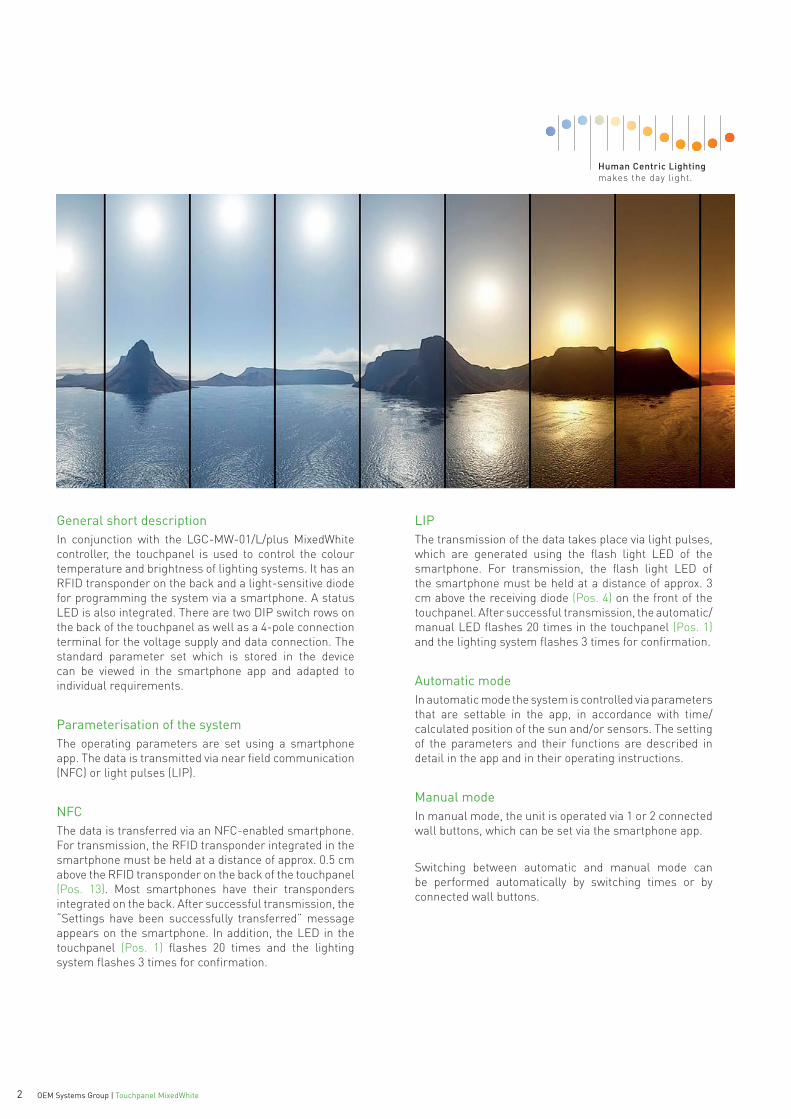
General short descriptionIn conjunction with the LGC-MW-01/L/plus MixedWhite controller, the touchpanel is used to control the colour temperature and brightness of lighting systems. It has an RFID transponder on the back and a light-sensitive diode for programming the system via a smartphone. A status LED is also integrated. There are two DIP switch rows on the back of the touchpanel as well as a 4-pole connection terminal for the voltage supply and data connection. The standard parameter set which is stored in the device can be viewed in the smartphone app and adapted to individual requirements.
Parameterisation of the systemThe operating parameters are set using a smartphone app. The data is transmitted via near field communication (NFC) or light pulses (LIP).
NFCThe data is transferred via an NFC-enabled smartphone. For transmission, the RFID transponder integrated in the smartphone must be held at a distance of approx. 0.5 cm above the RFID transponder on the back of the touchpanel (Pos. 13). Most smartphones have their transponders integrated on the back. After successful transmission, the “Settings have been successfully transferred” message appears on the smartphone. In addition, the LED in the touchpanel (Pos. 1) flashes 20 times and the lighting system flashes 3 times for confirmation.
LIPThe transmission of the data takes place via light pulses, which are generated using the flash light LED of the smartphone. For transmission, the flash light LED of the smartphone must be held at a distance of approx. 3 cm above the receiving diode (Pos. 4) on the front of the touchpanel. After successful transmission, the automatic/manual LED flashes 20 times in the touchpanel (Pos. 1)and the lighting system flashes 3 times for confirmation.
Automatic modeIn automatic mode the system is controlled via parameters that are settable in the app, in accordance with time/calculated position of the sun and/or sensors. The setting of the parameters and their functions are described in detail in the app and in their operating instructions.
Manual modeIn manual mode, the unit is operated via 1 or 2 connected wall buttons, which can be set via the smartphone app.
Switching between automatic and manual mode can be performed automatically by switching times or by connected wall buttons.

3 OEM Systems Group | Touchpanel MixedWhite 3 OEM Systems Group | Touchpanel MixedWhite
1.
5. 6.
4.
9.8.
7.
2. 3.
5 6
4
9.8.
7
1 2 3
Front touchpanel
Pos. 1 LED indicator: “Automatic” LED lights up when the system works in the automatic mode. The LED is off in manual mode. It flashes 20 times if the transfer of the parameters from the smartphone was successful.
Pos. 2 LED indicator: “On” LED lights up when the luminaires are switched on.
Pos. 3 LED indicator: “Off” LED lights up if the luminaires are switched off.
Pos. 4 Receiving diode for data transmission Receiver for programming via the flash light LED of a smartphone.
Pos. 5 Touchpad: Automatic/Manual Switches between automatic and manual mode. The selected mode is shown by the “Automatic” indicator (Pos. 1). In automatic mode, the LED lights up, in manual mode it is off.
Pos. 6 Touchpad: On Switches the luminaires on in automatic mode. The operating status is displayed via the LED indicator “On” (Pos. 2) and the LED indicator “Automatic” (Pos. 1).
Pos. 7 Touchpad: Off Switches the luminaires off. The operating status is displayed via the LED indicator “Off” (Pos. 3).
Pos. 8 Slider: Brightness The brightness of the luminaires is set via the slider. The further up the slider is moved, the brighter the luminaires become. Moving the slider in the lower range reduces the brightness of the luminaires. Via the slider, the brightness can be changed similar to a slide control. The automatic mode stays activated.
Pos. 9 Slider: Colour temperature The colour temperature of the luminaires is adjusted by moving the slider. The further upward the slider is moved, the warmer the colour tone of the light. Moving the slider in the lower range changes the colour tone towards a ‘cold white’. Via the slider, the colour tone can be changed similar to a slide control. The automatic mode is also terminated.
Controls and indicators
Pos. 1 LED indicator: “Automatic”Pos. 2 LED indicator: “On”Pos. 3 LED indicator: “Off”Pos. 4 Receiving diode for data transmissionPos. 5 Touchpad: Automatic / ManualPos. 6 Touchpad: OnPos. 7 Touchpad: OffPos. 8 Slider: BrightnessPos. 9 Slider: Colour temperature
Control panel of the touchpanel on the front
Please note:After switching the power off and on again, please do not touch the touchpanel for 15 seconds. A calibration takes place.
4 OEM Systems Group | Touchpanel MixedWhite
ON
1110
12
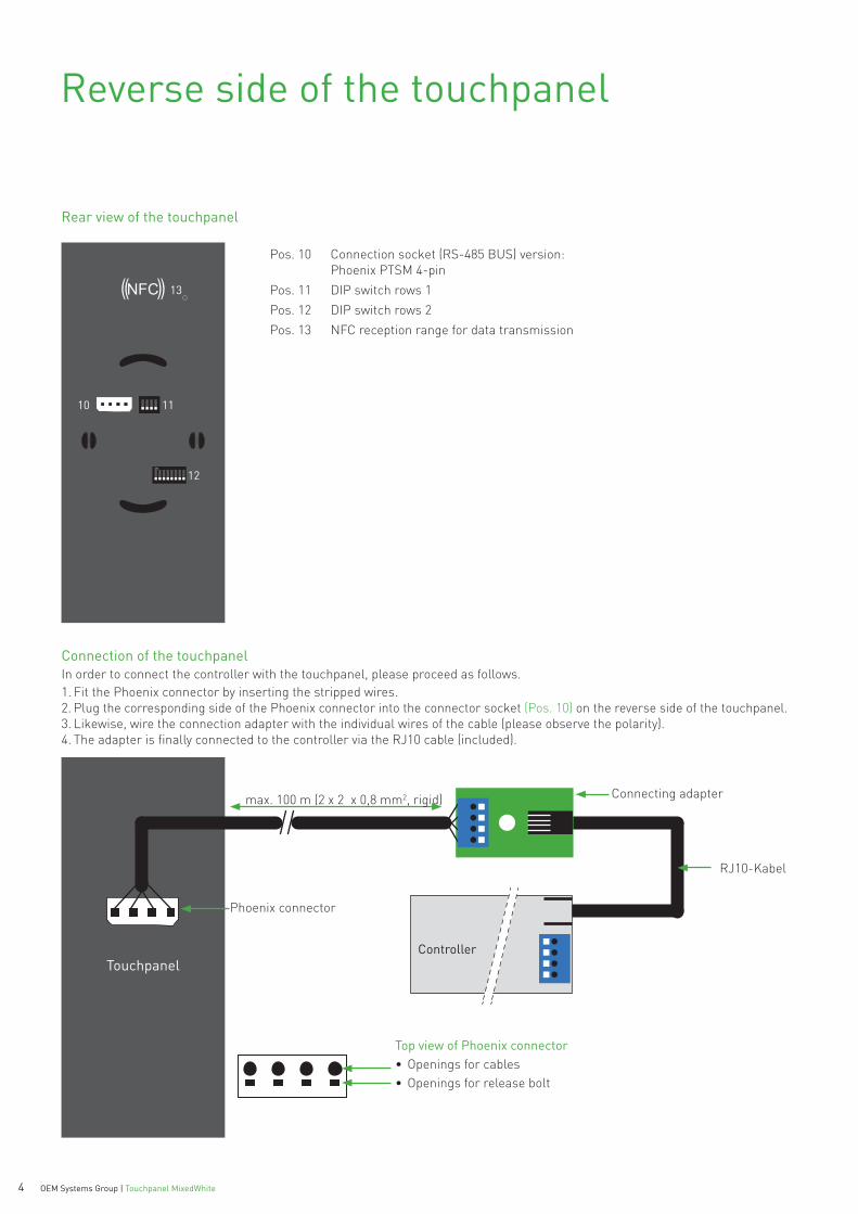
Reverse side of the touchpanel
Pos. 10 Connection socket (RS-485 BUS) version: Phoenix PTSM 4-pin
Pos. 11 DIP switch rows 1Pos. 12 DIP switch rows 2Pos. 13 NFC reception range for data transmission
Rear view of the touchpanel
Connection of the touchpanelIn order to connect the controller with the touchpanel, please proceed as follows.1. Fit the Phoenix connector by inserting the stripped wires.2. Plug the corresponding side of the Phoenix connector into the connector socket (Pos. 10) on the reverse side of the touchpanel.3. Likewise, wire the connection adapter with the individual wires of the cable (please observe the polarity).4. The adapter is finally connected to the controller via the RJ10 cable (included).
TouchpanelController
Phoenix connector
RJ10-Kabel
Connecting adapter
Top view of Phoenix connector• Openings for cables• Openings for release bolt
max. 100 m (2 x 2 x 0,8 mm2, rigid)
13
5 OEM Systems Group | Touchpanel MixedWhite 5 OEM Systems Group | Touchpanel MixedWhite
ON
1 2 3 4 5 6 7 8
ON
1 2 3 4 5 6 7 8
ON
1 2 3 4 5 6 7 8
ON
1 2 3 4 5 6 7 8
ON
1 2 3 4 5 6 7 8
Use of one touchpanel
1 2 3 4
Touch 1 Use of two touchpanels
1 2 3 4
ON
1 2 3 4
ON
Touch 1 (Master) Touch 2 (Slave) Use of three touchpanels
1 2 3 4
ON
1 2 3 4
ON
1 2 3 4
ON
Touch 1 (master) Touch 2 (slave 1) Touch 3 (slave 2)
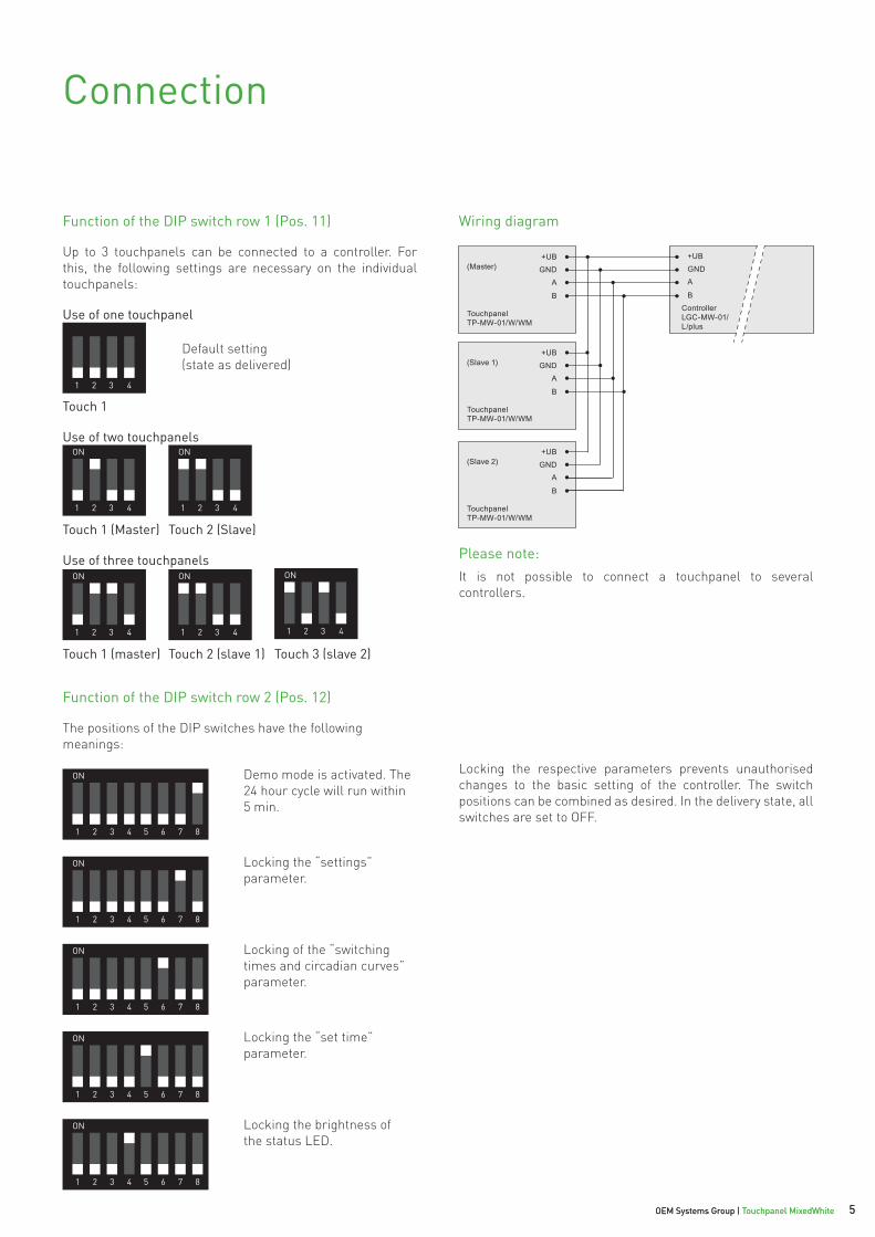
Connection
Up to 3 touchpanels can be connected to a controller. For this, the following settings are necessary on the individual touchpanels:
The positions of the DIP switches have the following meanings:
Locking the respective parameters prevents unauthorised changes to the basic setting of the controller. The switch positions can be combined as desired. In the delivery state, all switches are set to OFF.
Demo mode is activated. The 24 hour cycle will run within 5 min.
Locking the “settings” parameter.
Locking of the “switching times and circadian curves” parameter.
Locking the “set time” parameter.
Locking the brightness of the status LED.
Default setting (state as delivered)
Please note:It is not possible to connect a touchpanel to several controllers.
Wiring diagramFunction of the DIP switch row 1 (Pos. 11)
Function of the DIP switch row 2 (Pos. 12)
(Master)
TouchpanelTP-MW-01/W/WM
ControllerLGC-MW-01/L/plus
(Slave 1)
TouchpanelTP-MW-01/W/WM
(Slave 2)
TouchpanelTP-MW-01/W/WM
+UB
GND+UB
GNDA
B
A
B
+UB
GNDA
B
+UB
GNDA
B
6 OEM Systems Group | Touchpanel MixedWhite
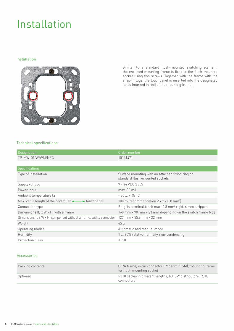
Installation
Similar to a standard flush-mounted switching element, the enclosed mounting frame is fixed to the flush-mounted socket using two screws. Together with the frame with the snap-in lugs, the touchpanel is inserted into the designated holes (marked in red) of the mounting frame.
Installation
Technical specifications
Designation Order numberTP-MW-01/W/WM/NFC 10151471
SpecificationsType of installation Surface mounting with an attached fixing ring on
standard flush-mounted sockets
Supply voltage 9 - 24 VDC SELVPower input max. 30 mAAmbient temperature ta - 20 … + 45 °CMax. cable length of the controller touchpanel 100 m (recommendation 2 x 2 x 0.8 mm2)Connection type Plug-in terminal block max. 0.8 mm2 rigid, 6 mm stripped Dimensions (L x W x H) with a frame 160 mm x 90 mm x 23 mm depending on the switch frame typeDimensions (L x W x H) component without a frame, with a connector 127 mm x 55.6 mm x 22 mm
Weight 65 gOperating modes Automatic and manual modeHumidity 1 ... 90% relative humidity, non-condensingProtection class IP 20
Packing contents GIRA frame, 4-pin connector (Phoenix PTSM), mounting frame for flush mounting socket
Optional RJ10 cables in different lengths, RJ10-Y distributors, RJ10 connectors
Accessories

OEM Systems Group BAG electronics GmbHKleinbahnstraße 27D-59759 ArnsbergTel.: +49 29 32-9000-9800Fax: +49 29 32-9000-9796 To
uchp
anel
ope
ratin
g in
stru
ctio
ns 1
6-12
| W
e re
serv
e th
e ri
ght t
o m
ake
tech
nica
l cha
nges
.