installation and operating instructions of … · installation and operating instructions of...
TRANSCRIPT

INSTALLATION AND OPERATING INSTRUCTIONS OF INSERTS FOR GAS-
FIRED FIREPLACES LEO 100 SERIES
LEO/100
LEO/L/100
LEO/P/100
LEO/LP/100

2
This manual, including all photographs, illustrations and trademarks, is protected by copyright. All rights reserved. Neither this manual, nor any of the material contained herein, may be reproduced without written permission. The information in this document is subject to change without notice. The manufacturer reserves the right to make corrections and changes in this manual without any obligation to notify anyone about it.

INSTALLATION AND OPERATING INSTRUCTIONS - LEO 100 SERIES
3
Contents
Preface 4 Introduction 4
Product description 5 Set components 7
Safety 8 Installation 8
Rules 9 Location 9 Connecting the device using a coaxial combustion air system 10 Installation of the control system 11 Receiver antenna 13 Connecting the device to the gas installation 13 Adjusting the control flame height of the burner 17 Adjusting the gas outlet pressure 18 Adjustment of the GV60 controller to supplies of various types of gas 20 Tightness test 20 Power supply connection 20 Construction of the device trim 21
Removing the glass 21 Decorative elements installation 22 Initial start-up 22 Operation 23
Control 23 User manual of the 6-symbol B6R-H9 control unit 26
Replacement of batteries 33 Maintenance 34 Gas technical parameters 36 Environmental protection 37 Guarantee 37 Possible problems and solutions 37 Illustrations 40 Notes 44

4
Thank you for your trust and purchase of the LEO 10 0 gas fireplace insert. This device has been designed for your safety and comfor t. We would like to express our conviction that you will be satisfied w ith your choice because of the commitment that was involved in the design and production of the gas fireplace. Prior to installation and use, please ca refully read all of the chapters in the manual. If you have any questions or conc erns, please contact our technical department. Any additional information is available online at www.kratki.pl.
Introduction Kratki.pl Marek Bal is a well-known manufacturer of heating equipment in both Poland and Europe. Our products are based on strict standards. Each insert manufactured by the factory is subjected to quality control during which it undergoes rigorous safety tests. The use of the highest quality materials in the manufacture ensures smooth and reliable operation of the device by end users. This manual contains all of the information necessary for proper installations, operation and maintenance of the LEO 100 gas inserts.
NOTE!!!
Installation, inspection and maintenance of the tig htness of the device can be carried out only by qualified fitters/technicians w ith licences appropriate for the given region.
Introduction The LEO 100 gas inserts are closed heating equipment powered with flammable gas. This device is CE marked and uses high-end automation to control gas. The inserts meet the stringent European directives with regard to safety, the environment and energy consumption.
The air supplied to the combustion chamber is drawn from outside of the housing via a coaxial chimney system. This eliminates the phenomenon of cooling the room due to a lack of need to mount a ventilation grille providing inflow of air necessary for the correct operation of the fireplace as in the case of heating with an open combustion chamber. This solution provides the user with security because it prevents passage of exhaust gases directly into the room where the fireplace operates. Before fitting the insert, please read these instructions. The information contained herein will allow you to obtain trouble-free operation of the device. This manual should be retained for the lifetime of the fireplace.

INSTALLATION AND OPERATING INSTRUCTIONS - LEO 100 SERIES
5
Product description The LEO 100 gas inserts are designed to be supplied with natural gas (NG) or liquefied propane-butane (LPG). The units may be available in four versions, depending on the type of glazing. The LEO 100 fireplaces are equipped with automation and security of the same type. Regardless of the model, how it is connected to the gas system and the flue system is identical.
LEO/100 LEO/L/100
LEO/P/100 LEO/LP/100
Figure 1. LEO 100 gas inserts The LEO 100 series has been designed for your safety and comfort. The user has the ability to remotely control the operation of the fireplace by a remote control. The air supply to the combustion chamber and flue gases exhaust are achieved by the use of a coaxial chimney system. The LEO 100 series is equipped with special means to prevent any uncontrolled outflow of gas from the system.

6
LEO/100
LEO/LP/100
LEO/L/100

7
INSTALLATION AND OPERATING INSTRUCTIONS - LEO 100 SERIES
LEO/P/100
Figure 2 Dimensions of the LEO 100 gas inserts
Set components
Please make sure that the set components were not damaged during transport. The inspection should be carried out in the presence of the fitter. Before installing the fireplace insert, please learn all of the elements that came with the device. In the case of any damage or omissions, please contact customer service. The user receives a set including:
� GV60M1 MetrikMaxitrol controller. � G6R-R9 MetrikMaxitrol receiver. � 6-unit symbol B6R-H8T5B remote control. � Clamp connector 8 mm. � Clamp connector 6 mm. � One-piece clamp connector 6 mm. � Screw plus 3/8'' - 2 pcs. � G60-ZUS09 interrupter block. � Control burner block G30-ZP2M. � Control burner nozzle - NG (number 27_2) � Seal under the control burner block. � Thermocouple G30-ZPT1500A. � Magneto wire. � The cable connecting the power module with the receiver, 90º. � Cables connecting the interrupter block with the receiver. � An 8-core cable connecting the gas controller with the receiver. � Reducing nipple 1/2 '' to 3/8 ''. � A set of decorative stones. � Gas connection cables having a diameter of 6 and 8 mm. � Distribution box. � Control burner nozzle - LPG (number 22) (Option). � Cable with a switch (Option). � Power module G60-ZBE (Option). � Lighting control module and a G6R-BEAV2 fan (Option). � 10-unit symbol B6R-H8TV14B remote control (Option).
8
� The cable connecting the G6R-BEAV2 module with the receiver (Option).
Safety Carefully read the following information:
� Connecting a fireplace to a gas installation and its maintenance can be carried
out only by a qualified fitter or a service technician of heating gas appliances. � If the control flame goes out, wait for at least five minutes before trying again. � It is strictly forbidden to make any modifications in the design of the fireplace. � Gas control system components must not be exposed to moisture. � Do not operate the unit without inserting its glass. � Do not touch hot parts of the fireplace, in particular, the glass. � While children or other unaware persons are near a working unit they should
not remain unattended. � It is forbidden to place decorative elements used for the lining of the
combustion chamber in front of the control flame. � Do not place flammable materials near the fireplace. � It is prohibited to place combustible materials in the combustion chamber. � If you feel gas leakage, do not operate the unit. As soon as possible, shut off
the gas, ventilate the room where the fireplace is and contact your service representative.
� Any cracked glass should be immediately replaced. � In the case of malfunctioning, cut off the gas supply and contact your service
representative.
Installation The fireplace is equipped with protective devices against uncontrolled outflow of gas from the main burner. Before connecting the appliance, please read all connection diagrams given in this chapter. The gas insert is adapted to be connected to a special coaxial chimney system allowing simultaneous supply of fire into the air and flue gas discharge to the outside of the building. To ensure proper operation, installation of the fireplace can only be done by qualified persons with appropriate licences. Prior to the release of gas to the insert, the fitter should:
� Perform a leak test for the gas connections. � Check the correctness of joining the components of the system. � Check for proper connection of the insert to the chimney system. � Perform test kindling in the insert.

9
INSTALLATION AND OPERATING INSTRUCTIONS - LEO 100 SERIES
� Check the correct operation of all components and system security.
Rules Install in accordance with local standards and regulations in force in the Member State or the region. Connection to the chimney, wall and roof passages and all kinds of items used to install the fireplace should be done in accordance with applicable standards of construction law.
The fireplace insert has been tested according to PN-EN-613 CIndependent gas-fired convection heaters.
Location Before connecting the device to a gas pipe and chimney, carefully choose the location of the device. The insert should be positioned so that the combustion air installation had the minimum number of bends. This will ensure appropriate chimney draft. It is also important that the flexible wires connected to the gas insert were not exposed to excessive bending. The fireplace must be at least 60 mm away from combustible building elements (Fig. 4). The temperature of the walls exposed to direct fire cannot be higher than 80°C. Under no ci rcumstances should you place the device in the hinterland of combustible materials, such as wooden furniture, carpets and curtains. Due to the possibility of ignition, it is prohibited to dry clothes, towels, etc. in the hinterland of the gas insert. The fireplace must be installed on a stable non-flammable surface. The gas insert is equipped with special adjustable feet and two adjustable mounting brackets allowing for attachment of the device to the wall. Never install the gas insert on the back or the side wall. Installation is permitted only in the vertical direction.
Figure 3. Levelling foot and adjustable bracket to attach to the wall

10
Figure 4. The minimum distance of the gas insert from the flammable housing components.
Connecting the device using a coaxial combustion air system Coaxial cables can have passages both through the wall and the roof of the building. In both cases, you must observe the construction law in the region. The maximum length of the flue pipe should not exceed 12 meters. Keep in mind that any 90° elbow is calculated as a 2 meter section, while any 45° e lbow corresponds to a straight coaxial 1 meter pipe. It is recommended to pass the flue pipe through the wall of the building by the use of 1 meter vertical section, angle 90° and a maximum of 3-meter horizontal section. The connection between the device and the coaxial cable must be sealed with high-temperature silicone. All ducts cannot be insulated. In the case of flue passage through the external wall of the building:
� Install the system in accordance with the applicable regulations, including any
difficulties related to the wind pressure on the terminal. � In the case of flammable walls, provide an additional distance of 5 cm between
the wall and the outer surface of the coaxial cables. The remaining space is to be filled with protective insulation against the ingress of moisture into the building.
� If the flue pipe is close to combustible walls, protect them with thermal insulation at a minimum distance of 25 cm.
� Installation of the coaxial system installation begins at the outlet of the fireplace 1 meter vertical section (the minimum height).
� Individual elements of the system should be connected by means of special clamps to ensure proper tightness.
� In the case of necessity, individual components of the system should be stabilized using wall mounts.

INSTALLATION AND OPERATING INSTRUCTIONS - LEO 100 SERIES
11
Figure 5. Coaxial system output method Gas inserts are designed for a specific combustion air supply. The chimney system used to connect the LEO 100 series is based on elements consisting of two coaxial conductors, wherein the outer diameter of 150 mm is responsible for providing air to the combustion chamber and the internal diameter of 100 mm for the discharge of exhaust gases. The coaxial cable should be terminated with a special thimble allowing for proper operation of the system. All system components must have the required approvals and CE certificates. The LEO Series 100 has been tested using a coaxial - air combustion system. In the event of condensate in the air-flue pipe, the fitter should apply a drainage element (a condensate collector).
Installation of the control system NOTE!!!
The device with its gas control system can be insta lled only with its factory settings. At this stage, do not install the battery in the receiver. Earlier connecting to a power supply may cause damage to th e electronics system.

12
NOTE!!!
Individual gas control system components, connect a ccording to the diagrams provided in this manual.
The standard gas control system includes a MaxitrolMetrik GV60 controller and a B6R-R8U receiver from which an antenna enables operation of the device using a remote control. Remote control gas components should be installed in the connection box. The connection box must be installed in an accessible place for possible repair or replacement of individual components of the system. Exposure of the electronic system to temperatures exceeding 60°C will result i n irreparable damage. Elements of the control system should be installed in a place where the temperature does not exceed 25°C. The maximum distance between the contr ol box and the gas insert is determined by the length of the cables connecting the GV60 gas control with the electrode and thermocouple. Do not extend the cables provided with the unit, as this may affect the control system malfunction. Keep in mind not to put the ignition cable too close to the metal parts. Contact of the ignition cable with the receiver housing can cause damage. Components of the system may not be exposed to moisture, dust, and factors affecting the formation of corrosion. The LEO 100 fireplace inserts can operate only with the gas control system supplied with the unit. When replacing individual components of the system, use only original parts available for purchase from the manufacturer. Plugs of individual wires are chosen in such a way as to prevent incorrect connection of components.
Figure 6. Mounting the gas controller with the receiver in the connection box

INSTALLATION AND OPERATING INSTRUCTIONS - LEO 100 SERIES
13
Figure 7. The wiring diagram of the system components for gas control (Standard option expanded with a switch on the cable connecting the receiver
and the circuit interrupter block)
Receiver antenna The antenna is part of the set, directly connected to the receiver's remote gas control B6R-R8U. It allows wireless control of the work of the fire using a remote control. By connecting the gas control system, special attention should be paid not to install the antenna too close to the ignition cable.
Connecting the device to the gas installation NOTE!!!
Depending on the type of the NG / LPG, an appropria te nozzle must be mounted in the control burner block. As standard, the unit is equipped with a burner adapted to natural gas (NG). In the case of connecting the fireplace to an LPG-powered system, please contact your dealer f or replacement of the main burner with the right one.

14
To be able to connect all of the system components of automatic gas control, you must first remove the glass front (Figure 15, p. 21element in the base of the main burner.
Figure 8. The procedure for removing
Passing individual wires through the casing of the gas insert, pay close attention to how they are sealed. Sealing is achieved by means of special bushings and heatresistant paper. Other elements should be sealed with high
Figure 9. The way of routing out and sealing the capillary cable, the magneto
wire, the tube of the main burner and the tube of the control burner
To be able to connect all of the system components of automatic gas control, you must first remove the glass front (Figure 15, p. 21-22) and remove the inspection element in the base of the main burner.
Figure 8. The procedure for removing the inspection element
Passing individual wires through the casing of the gas insert, pay close attention to how they are sealed. Sealing is achieved by means of special bushings and heatresistant paper. Other elements should be sealed with high-temperat
Figure 9. The way of routing out and sealing the capillary cable, the magneto wire, the tube of the main burner and the tube of the control burner
To be able to connect all of the system components of automatic gas control, you 22) and remove the inspection
the inspection element
Passing individual wires through the casing of the gas insert, pay close attention to how they are sealed. Sealing is achieved by means of special bushings and heat-
temperature silicone.
Figure 9. The way of routing out and sealing the capillary cable, the magneto wire, the tube of the main burner and the tube of the control burner

INSTALLATION AND OPERATING INSTRUCTIONS - LEO 100 SERIES
15
NOTE!!! All activities associated with connecting the devic e to the gas installation should be carried out with the power disconnected. The insert installation can only be done by a qualified fitter/technician with appropriate licences.
NOTE!!!
It is absolutely forbidden to use open fire during the installation process of the gas insert. Failure to follow instructions could re sult in fire or explosions, causing severe damage, bodily injury or even death.
Technical specifications of the gas control system used in the LEO 100 series:
PERFORMANCE ACCORDING TO THE DIRECTIVE 2009/142/EEC and DIN EN 298, DIN EN 126, DIN
EN 13611
FUEL Gaseous fuels of the first, second and third family, according to EN-437
PRESSURE DROP/CAPACITY
2.5 mbar for 1.2 m3/h
ADJUSTMENT RANGE Class C, according to EN 88
ADJUSTING THE REGULATOR
5 to 40 mbar (50 to 400 kPa)
MOUNTING POSITION the module cannot be mounted with the breaker block downwards. The control position can be adjusted in the range from 0° to 90° relative to its home posit ion (Fig. 11).
MAXIMUM PRESSURE OF INPUT GAS
MAIN GAS INLET CONNECTION
CONTROL BURNER CONNECTION
DISCHARGE OF THE MAIN GAS INLET AND OUTLET
MAXIMUM TIGHTENING TORQUE
THERMOCOUPLE /BREAKER BLOCK
50 mbar (5 kPa)
Reducing nipple 1/2 '' to 3/8 ''
M10x1 for a pipe of 6
mm From the side or
bottom
Inlet and outlet connection ⅜": 35 Nm Control burner connection: 15 Nm
M10x1, M9x1, M8x1

16
IGNITION Piezoelectric ignition
ALLOWABLE TEMPERATURE LIMIT
Controller: 0 ° C to 80 ° C, Receiver without batteries: 80 ° C Receiver with batteries: 55 ° C Remote control: 60 ° C Ignition cable: 150 °C
The gas control system used in the LEO 100 series meets the requirements for appliances burning gaseous fuels in Directives 2009/142/EEC and DIN EN 298, DIN EN 126, DIN EN 13611. The system can be supplied with a gaseous fuel of the first, second and third family according to EN- 437. First, make sure that the connected device is intended to be supplied with the type of gas contained in the gas installation. All the necessary information about the required parameters of the gas can be found on the nameplate of the fireplace. Before connecting the gas supply pipes, it is necessary to purge them to remove metal filings and other contaminants from their interior. The automatic gas control should be protected from moisture and dust. These factors may cause irreparable damage to individual components. Gas supply pipes to the fireplace should be equipped with a ball valve of ½ inch in diameter. Individual elements of gas installation cannot be sealed using a Teflon tape or PTFE tape (Please use the sealing elements supplied with the unit). If the gas installation needs to be connected to a settler, install it according to Fig. 10. The settler protects the controller from gas contaminants.
Fig. 10 How to install a settler (if required)

INSTALLATION AND OPERATING INSTRUCTIONS - LEO 100 SERIES
17
Fig. 11 shows the GV60 controller at its home position with the breaker block pointing downwards. The module cannot be mounted upside down. The control position can be adjusted in the range from 0° to 90° relative to its home position (also vertical). Please note that all unused gas inlets or outlets should be protected with suitable plugs.
Figure 11. The GV60 controller in its home position NOTE!!!
You may not remove screws on the enclosure. Do not connect the gas controller, if the marking paint, located on the co mponents has been damaged.
Adjusting the control flame height of the burner The factory control flame height is set to the maximum. The thermocouple head should be within the control flame. To adjust the control flame height:
1. Manually set the manual mode dial to "ON" 2. Using a screwdriver, pierce the membrane protecting the adjusting screw (Fig.
12.) 3. Turn the screw clockwise to decrease the control flame height. To increase the
control flame height, turn the adjusting screw in counter-clockwise.

18
Figure 12. Adjusting the control flame height of the burner
Adjusting the gas outlet pressure
1. Connect the pressure gauge to the measuring point of the output pressure. To do so, first remove the metal insert located in the control enclosure.
2. Set the manual mode dial and the main valve knob to "ON". 3. The pressure regulator is in the upper part of the controller enclosure. To
enable the adjustment, remove the plastic cap (Fig. 13). 4. Turn the regulator screw to set the desired pressure value of the main burner
(high flame). To increase the pressure, turn the regulator screw clockwise or decrease it by turning the screw counter-clockwise.
5. After setting the pressure, secure the screw by installing a plastic plug. 6. If you do not need to make any other adjustments, remove the gauge and
secure the port of the measuring point. If, despite the adjustment, the desired pressure was not achieved, check the pressure of the gas supplied using a gauge connected to the measurement point of the input pressure. If the inlet pressure is within the normal range, replace the controller; otherwise take the necessary steps to ensure proper gas pressure.

19
INSTALLATION AND OPERATING INSTRUCTIONS - LEO 100 SERIES
Figure 13. Adjustment method of the discharge pressure Adjusting the minimum flame height of the main burn er
1. Set the main valve knob to "OFF". Turn it clockwise until valve opening. 2. The minimum flame height of the main burner can also be adjusted by
tightening the adjusting screw (Fig. 14). The adjustment screw is set so as to provide the maximum flame height.
3. Turn the screw clockwise to reduce the minimum height of the flame. 4. Depending on the version of the controller, the minimum flame height of the
main burner can be set at the factory by the manufacturer or can be adjusted by the installer.
Figure 14. Adjusting method for the minimum flame height of the main burner

20
Adjustment of the GV60 controller to supplies of various types of gas
The GV60 controller can be adapted so that it can work with specific types of gases. Gas pressure control and minimum flow are performed according to the instructions above.
NOTE!!!
To adjust the controller to supply with propane - b utane (LPG), it is necessary to block the pressure regulator, through the maximu m tightening the adjusting screw.
Tightness test After connecting the system to the gas network it is essential to check the tightness of the connections made with a special sensor. In the case of leaks, shut off the gas supply shut-off valve and repeat the steps involved in installing various parts of the system.
Power supply connection NOTE!!!
Connect the power supply only after connecting the combustion air system and any gas control system components.
The B6R-R8U receiver is powered by four 1.5V AA batteries. Pay special attention to locate the wiring connecting the gas control and the receiver away from hot parts of the fireplace. The need to replace the batteries in the remote control is indicated by the indicator displayed in the upper right corner of the display, while short beeps periodically appearing for three seconds immediately after starting the firing process in the fireplace indicate the need to replace the batteries in the receiver. Used batteries located in the receiver can overheat, spill or even explode. Do not use batteries that have been exposed to the sun, moisture, heat or vibration. Install only batteries of the same type and the same manufacturer. Do not install new batteries with worn ones. The kit can optionally include the G60- ZB90 power module. This module is powered by four 1.5V AA batteries and should be connected directly to the receiver in the place of the AC adapter connection. The additional power supply module eliminates the need for batteries in the receiver. Optionally, customers can buy a cable connecting the interrupter block and the receiver for the gas control system, equipped with a switch. The switch also protects the system against uncontrolled flow of gas through the controller.

INSTALLATION AND OPERATING INSTRUCTIONS
Construction of the device trim
Before performing the trim, protect the gas control system components Fireplace trim should be made of nonceiling) according to the current construction regulations. If the fireplace is powered by natural gas (NG), the exhaust grille should be placed under the ceilinliquid propane - butane (LPG) requires from the fitter execution of enclosures equipped with the exhaust grille above ground level.
Removing the glass
ATTENTION !!!
Removing the glass should only take place off coole d fireplace with gas suoff and disconnected power supply.
The device is equipped with a heat800°C. To exchange it, in the first place, remove t he side grilles. The grills are fitted with special splines. The side glass cAllen screwdriver. In the next step, remove the lower grille and unscrew the remaining glass clamping strip. After the above steps, you can now easily remove the glass. Depending on the model of series 100 LEO, dislightly different from the one shown.
INSTALLATION AND OPERATING INSTRUCTIONS - LEO 100 SERIES
Construction of the device trim
Before performing the trim, protect the gas control system components Fireplace trim should be made of non-combustible materials (including its floor and ceiling) according to the current construction regulations. If the fireplace is powered by natural gas (NG), the exhaust grille should be placed under the ceilin
butane (LPG) requires from the fitter execution of enclosures equipped with the exhaust grille above ground level.
Removing the glass
Removing the glass should only take place off coole d fireplace with gas suoff and disconnected power supply.
The device is equipped with a heat-resistant glass that withstands temperatures up to 800°C. To exchange it, in the first place, remove t he side grilles. The grills are fitted with special splines. The side glass clamping strips should be unscrewed with an Allen screwdriver. In the next step, remove the lower grille and unscrew the remaining glass clamping strip. After the above steps, you can now easily remove the glass. Depending on the model of series 100 LEO, disassembly of the glass may be slightly different from the one shown.
LEO 100 SERIES
21
Before performing the trim, protect the gas control system components from dirt. combustible materials (including its floor and
ceiling) according to the current construction regulations. If the fireplace is powered by natural gas (NG), the exhaust grille should be placed under the ceiling. Supplying
butane (LPG) requires from the fitter execution of enclosures
Removing the glass should only take place off coole d fireplace with gas su pply
resistant glass that withstands temperatures up to 800°C. To exchange it, in the first place, remove t he side grilles. The grills are fitted
lamping strips should be unscrewed with an Allen screwdriver. In the next step, remove the lower grille and unscrew the remaining glass clamping strip. After the above steps, you can now easily remove the
sassembly of the glass may be

22
Figure 15. Procedure for removing the glass
Decorative elements installation
NOTE!!!
The manufacturer recommends the use of decorative e lements, optionally supplied with the device. Kratki.pl Marek Bal is no t liable for damages resulting from the use of decorative elements other than reco mmended.
The combustion chamber, depending on the user's preferences, can be lined with one of several sets of decorative elements. The decorative elements are made of non-combustible material. The use of flammable components in the device is forbidden.
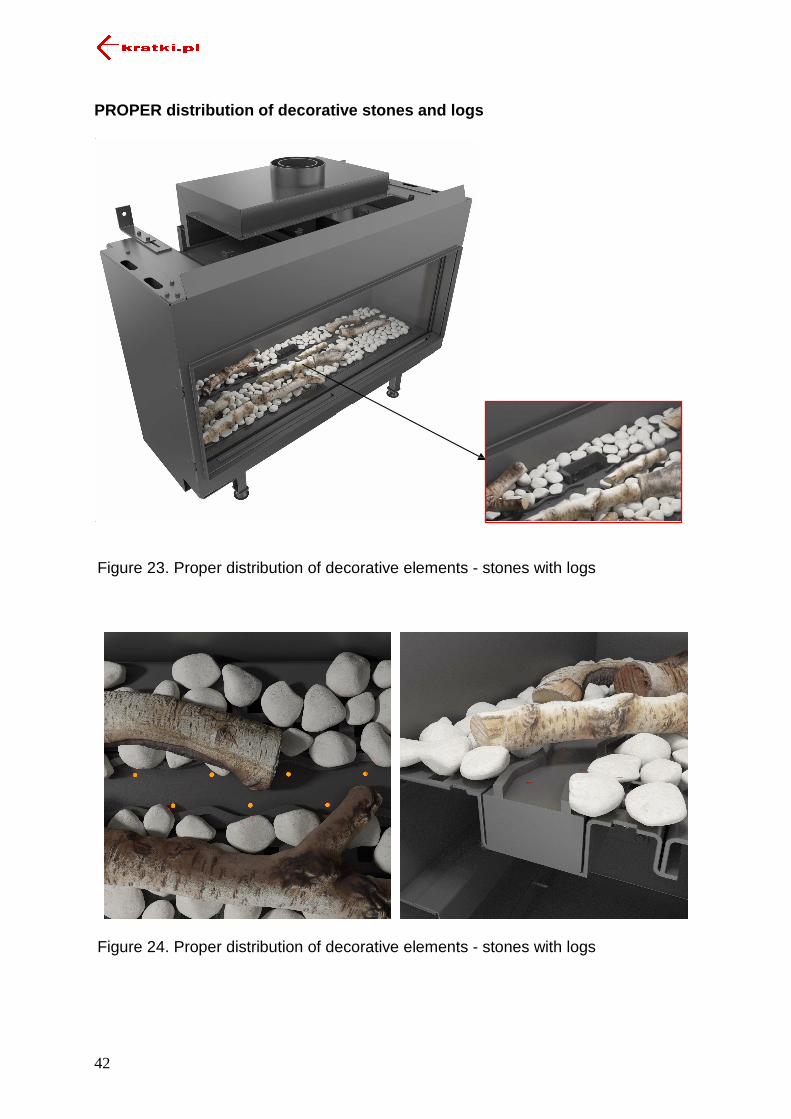
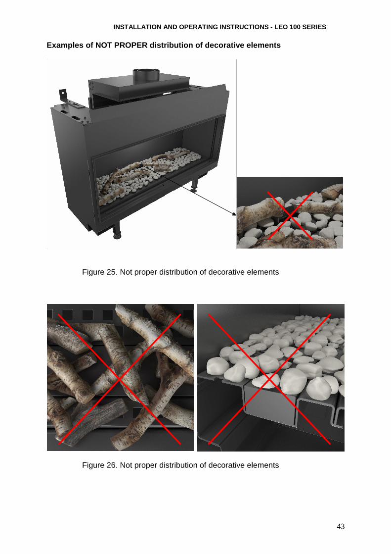
To mount decorative elements, it is needed to be remove the front glass only. The elements should be arranged in such a way as not to obscure the flame control and the burner outlet openings, otherwise it may cause incorrect operation of the fireplace. The main burner of the fireplace is equipped with spacers to facilitate correct placement of decorative elements. Distribution of the elements in the combustion chamber of the device should allow the free flow of air around the main burner and the control flame. The ceramic elements should not touch the glass, as it may cause damage. Correct and incorrect placements of decorative elements are shown on pages 40-43.
Initial start-up
Before the first use of the fireplace, make sure that all connections of individual elements of the system were made in accordance with the instructions. Incorrect cabling of the gas control system can cause damage.

23
INSTALLATION AND OPERATING INSTRUCTIONS - LEO 100 SERIES
The first few start-ups can contribute to smell which may persist even several hours after operation. This is a phenomenon caused by paint burning. Pets and birds can react sensitively to secreted fumes. To speed up the process of the paint burning, warm the fireplace for a few hours, setting the maximum height of the flame. If, during the first fire, there is sediment on the inside of the glass surface, remove it using a glass cleaner. The first operation of the gas insert must be carried out within a well-ventilated area.
When heating using gas you may encounter staining walls and ceilings. It is caused by the convection movement of air and thus dust particles contained therein. A partial solution to this problem is frequent ventilation of the room in which the gas insert operates. If the fireplace is installed in a new building, you should wait at least 6 weeks before lighting it for the first time to remove construction moisture from the walls, floor and ceiling.
Operation The LEO 100 gas inserts are controlled wirelessly with a remote control. The system, as standard, is powered by four 1.5V batteries installed in the receiver. Short cyclical signals appear for about three seconds when you try to ignite the gas insert and it is necessary to replace the batteries in the receiver. A long beep means that the controller switch on the line between the receiver and the interrupter block (option) is in position "O" or one of the wires connecting the receiver to the controller is not connected properly. Set the switch to "I". If the control flame does not light, it is necessary to shut off the gas supply shut-off valve and contact a service technician. If, within six hours, the device does not receive a command from the user, a system of automatic gas control will reduce the main burner flame to the minimum. In the case of continuous operation without user intervention for five days after the last entry of settings, the system will turn off the unit and cut off the gas supply. Before the battery in the receiver is fully discharged, the controller will automatically shut off the gas supply to the fireplace.
Control NOTE!!!
The remote control should always be kept out of the reach of children and other persons unaware, not capable of assessing the conse quences of their actions.
The user gets the device along with the included remote control, type B6R-H9 (Fig. 16).

24
Figure 16. B6R-H9 remote control
NOTE!!! The B6R-H9 remote control units have a built-in sen sor used in the thermostat mode. The unit continuously measures the ambient t emperature and compares it with the temperature set on the thermostat. It s hould be kept in a dark place, to rule out measurement errors associated with dire ct sunlight.
The LEO 100 inserts are equipped with a gas control system allowing the user to remotely lighten the fireplace and to fully control the hearth. To enable operating the insert from the remote control:
� Make sure that the shut-off valve installed on the gas supply to the fireplace is
open. � If the system is equipped with a cable with a switch, set it to "I" (on). The main
valve knob is switched automatically. � Manually set the manual mode dial to "ON".
Never use tools to change the position of knobs. Changing the position of the knobs can only be made by hand, otherwise you may damage the controller. In the case of locking the knobs, contact your service representative.
Figure 17. GV60 controller settings for remote starting the fireplace
25
INSTALLATION AND OPERATING INSTRUCTIONS - LEO 100 SERIES
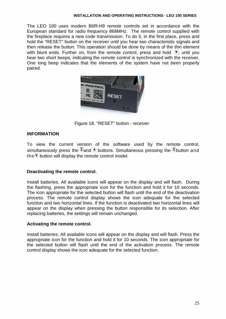
The LEO 100 uses modern B6R-H9 remote controls set in accordance with the European standard for radio frequency 868MHz. The remote control supplied with the fireplace requires a new code transmission. To do it, in the first place, press and hold the "RESET" button on the receiver until you hear two characteristic signals and then release the button. This operation should be done by means of the thin element with blunt ends. Further on, from the remote control, press and hold , until you hear two short beeps, indicating the remote control is synchronized with the receiver. One long beep indicates that the elements of the system have not been properly paired.
Figure 18. "RESET" button - receiver INFORMATION
To view the current version of the software used by the remote control, simultaneously press the and buttons. Simultaneous pressing the button and the button will display the remote control model.
Deactivating the remote control.
Install batteries. All available icons will appear on the display and will flash. During the flashing, press the appropriate icon for the function and hold it for 10 seconds. The icon appropriate for the selected button will flash until the end of the deactivation process. The remote control display shows the icon adequate for the selected function and two horizontal lines. If the function is deactivated two horizontal lines will appear on the display when pressing the button responsible for its selection. After replacing batteries, the settings will remain unchanged.
Activating the remote control.
Install batteries. All available icons will appear on the display and will flash. Press the appropriate icon for the function and hold it for 10 seconds. The icon appropriate for the selected button will flash until the end of the activation process. The remote control display shows the icon adequate for the selected function.

26
NOTE!!!
If, when you try to light it, the control flame goe s out, wait for at least five minutes before trying again to light the fireplace.
NOTE!!!
If, after four attempts to light the fireplace, the control flame will not ignite, close the gas shut-off valve to the appliance and contact your service representative.
User manual of the 6-symbol B6R-H9 control unit
To change the temperature unit, simultaneously press the
buttons. You can choose between Celsius and Fahrenheit degrees.
Choosing °F will automatically set the clock in a 1 2-hour format, while the choice of °C sets the clock in a 24-hour format.
Setting the temp erature unit

27
INSTALLATION AND OPERATING INSTRUCTIONS - LEO 100 SERIES
1. To be able to adjust the day of the week, press the
button and the button.
2. Press or to select a number corresponding to the day of the week (1 - Monday, 2 - Tuesday 3 - Wednesday 4 - Thursday, 5 - Friday, 6 - Saturday, 7 Sunday)
3. Simultaneously press the button and the button. Hours will flash.
4. Set the hour using the and buttons.
5. Simultaneously press the button and the button. Minutes will flash.
6. Set the minutes using the button and the button.
7. To confirm the setting, simultaneously press a n d or wait.
Enabling:
To activate the Child Proof function press the and buttons. The display shows the icon.
Disabling:
To deactivate the Child Proof function press the and buttons. The icon will disappear.
Lighting the fire in the fireplace with a single bu tton (default setting)
� Press the button until you hear two short beeps. Starting the firing sequence is confirmed by the occurrence of a flashing icon on the display of the burner. Release the button.
� Kindling the control flame is confirmed by a single signal. � After kindling the main burner, the remote control
automatically switches to the manual mode.
Manual mode
Child Proof
Time settings

28
Lighting a fire in the fireplace with two buttons
� Simultaneously press the button and the button
until you hear two short beeps. Starting the firing sequence is confirmed by the occurrence of a flashing icon on the display of the burner. Release the button.
� Kindling the control flame is confirmed by a single signal. � After kindling the main burner, the remote control
automatically switches to the manual mode.
Information: To change the kindling method, immediately after you install the batteries in the
remote control, hold the button for 10 seconds. The remote control display shows "ON" and a flashing digit corresponding to the current settings.
1 - Lighting a fire by pressing.
2 - Lighting a fire by pressing the and the buttons.
End of the procedure of changing the method of lightening a fire is confirmed with the display reading the appropriate number.
NOTE!!!
If, after several attempts to fire, ignition of the control flame does not take place, set the main valve knob to "OFF" and refer to the s ection "Possible Problems and Solutions".
Standby or off mode
To make the unit switch to the standby mode, hold the button until the main burner is extinguished.
To turn the device off, press . The control flame will be extinguished.
Before attempting to re-start the fireplace, wait 5 seconds.

29
INSTALLATION AND OPERATING INSTRUCTIONS - LEO 100 SERIES
Adjusting the height of the flame
To increase the height of the flame, press and hold the button.
To reduce the height of the flame or put the fireplace into the
standby mode, press and hold .
The minimum height of the flame
To reduce the burner flame to the minimum height, double-
press the button. The display shows the „LO” symbol
The maximum height of the flame
To increase the burner to the maximum value, double-press
the button. The display shows the „HI” symbol.
Enabling/Settings
1. Press and hold until you see the icon. The hours' box will flash.
2. Enter a value using the and buttons.
3. To confirm, press . The minutes' box will flash. 4. Enter a value using the and buttons. 5. To confirm, press or wait.
Sleep timer
Setting the minimum and maximum height of the flame

30
Disabling:
To deactivate the timer, press the button. the icon will disappear with countdown time.
Information:
After the expiry of the countdown time, the fireplace will be extinguished. The sleep timer only works in different modes: Manual, Thermostat and Eco. The maximum value of the timer is 9 hours and 50 minutes.
Thermostat mode
The room temperature is measured and compared with the temperature set on the thermostat. The flame height is automatically adjusted so as to reach the set temperature.
Programmed mode
Programmes 1 and 2 can be freely modified. You can set the time on and off of the fireplace at a given temperature.
Enabling and disabling the thermostat
Enabling:
Press the button. The display shows the icon and the preset temperature as the first and the actual room temperature.
Disabling:
1. Press the button .
2. Press the button of the button.
3. Press the button, to enter the Programmed mode.
Thermostat mode
Modes

INSTALLATION AND OPERATING INSTRUCTIONS - LEO 100 SERIES
31
Thermostat settings
1. Press and hold until you see the icon . The
temperature displayed flashes.
2. To set the desired temperature use the and buttons.
3. To confirm, press or wait.
Enabling the programmed mode
Press the button. The display shows the icon and the 1 or 2 symbols and „ON” and „OFF”.
Disabling the programmed mode
1. Press the button or the button, or the button to go to the manual mode.
2. Press the button, to go to the Thermostat mode.
Information:
Entering the switch-on temperature of the thermostat will automatically set the same value for the switch-on temperature of the programmed mode.
Default settings: Temperature of switching on: 21°C Temperature of switching ff: „--” (only the control flame)
Programmed mode

32
Temperature settings
1. Press and hold the button until you see the flashing
icon . "ON" and the switching off temperature will be displayed (set in the thermostat mode).
2. To continue, press or wait. The display shows the icon, the „OFF” symbol and a flashing value to symbolize the switching off temperature.
3. Set the desired temperature using the or buttons. 4. To confirm, press .
Setting the days
5. The display flashes „ALL ”. Press the button or the button to select one of the three options to enter (ALL, SA:SU, 1, 2, 3, 4, 5, 6, 7 ).
6. To confirm, press .
SA:SU symbols, respectively, mean Saturday and Sunday. Individual numbers correspond to the days of the week (e.g. 1 Monday 2 - Tuesday 3 - Wednesday 4 - Thursday, 5 - Friday, 6 - Saturday, 7 - Sunday).
Switching on time settings (Programme 1)
„ALL ” option selected
7. The display shows , 1, „ON”, then for a while you will
see the „ALL ” symbol. Subsequently, the hour will begin to flash.
8. Set the hour using the and buttons. 9. To confirm, press . The display shows the icon, 1,
„ON”, then for a while you will see the „ALL ” symbol. Subsequently, the minutes will begin to flash.
10. Set the minutes using the and buttons. 11. To confirm, press .
Switching off time settings (Programme 1)
12. The display shows , 1 , „OFF”, then for a while you will see the „ALL” symbol. Subsequently, the hour will begin to flash.

INSTALLATION AND OPERATING INSTRUCTIONS - LEO 100 SERIES
33
13. Set the hour using the and buttons.
14. To confirm, press . The display shows , 1, „ON”, then for a while you will see the „ALL ” symbol. Subsequently, the minutes will begin to flash.
15. Set the minutes using the and buttons. 16. To confirm, press .
Information:
� Subsequently, the user can enter the time on and off for Programme 2. If not, Programme 2 will remain inactive.
� Temperature settings for enabling and disabling Programmes 1 and 2 are the
same for all options (ALL, SA: SU, 1, 2, 3, 4, 5, 6, 7 ). Entering new settings for switching on and off temperatures automatically sets the default preset values.
� Entering new settings for switching on and off time for Programmes 1 and 2 will
set new values as the default. To restore the factory settings for programmes 1 and 2, reset the remote control by removing the battery.
Replacement of batteries
Batteries in the receiver, remote control or the power supply module can overheat, spill or even cause an explosion. Do not use batteries that have been exposed to the sun, moisture, heat or vibration. Install only batteries of the same type and the same manufacturer. Do not install new batteries with worn ones. The remote control is powered by two AAA batteries. The B6R-R8U receiver and the G60-ZB90 power module are powered by four AA batteries 1.5V. The battery life in the case of the remote control and the receiver is estimated at about 1 heating season. The device manufacturer recommends the use of alkaline batteries because of the lower risk associated with unsealing. It is also permissible to use rechargeable batteries. When removing batteries, do not use tools that can cause a short-circuit. Replacing batteries with conductive objects can permanently damage the electronic components of the remote control and the receiver.
Replacement of the batteries in the remote control:
� Remove the cover located on the rear of the remote control. � Gently remove the used batteries from the remote control.

34
� Install new AAA batteries observing the polarity markings (+/-). � Replace the cover on the back wall of the remote
control. Replacing batteries in the receiver/power supply
module:
� Open the cabinet door panel. � Carefully remove the B6R-R8U receiver/G60-ZB90 power module . � Remove the cover. � Remove the used four AA batteries and install new, paying attention to the
polarity markings (+/-) on the receiver/power module. � Replace the cover on the cover receiver/supply module.
NOTE!!!
Replacing batteries in the receiver/power supply mo dule can only be done on a cool fireplace with the gas supply cut off.
NOTE!!!
Batteries are classified as hazardous chemical wast e, so, after using them, they should not be disposed of with other household wast e.
Maintenance NOTE!!!
All maintenance work should be carried out on a coo l fireplace with gas supply off and disconnected power supply.
NOTE!!!
Maintenance of the gas insert and the combustion ai r system can only be done by a qualified service technician.
� The device requires periodic inspection at least once a year. � Cleaning the chimney system and a review should be conducted at least once
a year. � Glass with cracks and scratches should be immediately replaced with new
ones. � It is forbidden to make any changes in the design of the device. � Fireplaces should not be cleaned with caustic agents. � When replacing individual components, use only original spare parts available
from the manufacturer.

INSTALLATION AND OPERATING INSTRUCTIONS - LEO 100 SERIES
35
Checklist:
No. Range Activity
1
General inspection
Perform lighting a fire in the fireplace. Check the operation of all safety systems. Check that the main burner flame burns steadily. Check that the main burner flame burns evenly. Check the batteries in the receiver and the remote control do not need to be replaced. Check the operation of all modes in the control unit.
2
Glass inspection
Make sure that the glass does not have any cracks Make sure the glass fits tight to the body of the fireplace. Check the wear of the glass sealing cords. If necessary, replace the sealing cords. Check the degree of dirtiness of the glass. If necessary, clean the glass.
3
Switch box inspection
Check the tightness of gas connections. Make sure the switch box has adequate ventilation. Check that the cables connecting the controller to the receiver are not damaged. Make sure gas control system components are not exposed to high temperatures. Make sure that the switch box is not exposed to moisture. Check that the connecting cords have no signs of corrosion.
4
Combustion chamber inspection
Make sure the control burner is not obscured by decorative elements. Check if the thermocouple is within the control flame. Check whether the combustion chamber requires cleaning. Make sure all air inlets to the combustion chamber are clear. If necessary, clear the openings. Check the tightness of the body of the fireplace. Check the combustion chamber with respect to any signs of corrosion. If necessary, remove corrosion and cover losses with a new coating of paint. Check that the main burner ignites smoothly.
5
Control of the chimney system
If possible, check the tightness of the chimney system. Check the coaxial combustion air system patency.

36
6
Control device inspection
Check that the receiver antenna is not damaged. Make sure that the main valve knob and the manual mode dial work correctly. Check if there is no insulation damaged in the circuits. Make sure the AC power cord is not damaged. Make sure that the control system components are not exposed to overheating.
7
Trim inspection
Make sure the gas insert trim has no cracks. Make sure that combustible elements are at a safe distance from the fireplace trim.
8
Decorative elements
Make sure that decorative elements do not require cleaning. Make sure decorative elements are not in contact with the glass. Make sure that decorative elements are not damaged.
Gas technical parameters
Gas group and family - 2E, 2H 3P Reference gas - G20 G31
Destination
-
AT, BE, CY, CZ, DK, EE, ES, DE, FI, FR, GR, GB, HR, TR, IE,
IT, LT, LU, LV, NO, PL, PT, RO, SE, SI, SK
BE, CZ, ES, FR, GR,
GB, HR, TR, IE, IT, LT, NL, PL, PT, SI, SK
Device category - I2E, I2H I3P Nominal connection pressure
mbar
20 37
Maximum connection pressure
25 45
Minimum connection
17 25
Gas pressure behind the regulator for the rated load
13.0 25
Gas pressure behind the regulator for minimum load
2.5 6.5
Gas nozzle of the main burner [mm] 3.1 1.8 Marking the nozzle - NG 31 LPG 18
Gas nozzle of the controller burner
[mm] nozzle with 2 holes Ø 0.25
0.25
Rated thermal load, according to Hi
kW
11.2 9.5
Rated minimum load, according to Hi
4.7 4.7

37
INSTALLATION AND OPERATING INSTRU CTIONS - LEO 100 SERIES
Environmental protection
� All elements of the packaging in which the gas insert was supplied should be disposed of in an appropriate manner for their type.
� Due to the heavy metal included, the batteries are classified as hazardous chemical waste, so, after use, they should be thrown into special containers for hazardous waste.
� If the device operation is over, you should dispose of it. The user is obliged to submit the fireplace to an appropriate institution handling recycling this type of equipment.
Guarantee Kratki.pl Marek Bal grants you a guarantee of quality for the smooth functioning of the goods listed on the sales proof. The guarantee is given for the period from the date of purchase (based on the warranty card and/or the purchase document. The warranty period starts at the time of the original purchase of the product by the first end user. The product may consist of several different parts and the different parts will have different guarantee periods. The manufacturer offers a 2-year warranty for smooth operation from the date of purchase of the insert. Sealing of the fireplace will be warranted for a period of 1 year from the date of the purchase of the insert. The warranty does not cover: insulating panels, heat-resistant ceramics. The use of the fireplace insert, the connection method to the chimney and operating conditions must comply with the instructions. The basis for guarantee repairs, free of charge, is the product guarantee card. Any guarantee card without a date, stamps, signatures, as well as including any amendments made by unauthorized persons expires. Customer powers under the guarantee will expire automatically: after the warranty period. Any damages caused by improper handling, storage, poor maintenance, incompatible with the conditions laid down in the operation and maintenance manual and due to other reasons not attributable to the manufacturer, will void the guarantee. For more information, please visit www.kratki.pl.
Possible problems and solutions NOTE!!!
Removal of defects or replacement of system compone nts for gas control can only be done by an authorized service technician.

38
There are many factors that could affect the gas insert malfunction. To exclude a possible fault in the unit or the automatic gas control system, be sure that the fireplace is connected in accordance with these instructions. The table below shows how to proceed in the case of individual symptoms. NOTE!!!
Making replacement of damaged parts, use only origi nal components offered by the manufacturer.
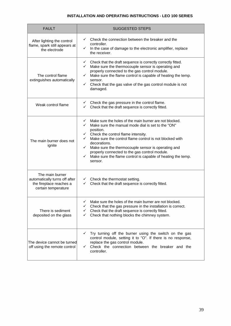
FAULT SUGGESTED STEPS
The device will not start (no audible confirmation
of the ignition procedure)
� Replace the batteries in the remote control and the receiver. � If the receiver is powered by the power module assess its
performance. � Reset the receiver and program a new transmission code. � Make sure the receiver antenna is properly installed and not
damaged.
No voltage on the
controller coil (there are no specific
„clicks”)
� Make sure the switch cord in the gas control module is not damaged.
� Short cyclical signals appearing when you try to switch on the fireplace indicate the need to replace the batteries in the receiver.
� For one long beep:
− Make sure that the switch on the connecting cable from the gas control module with the receiver is set to "I". (Option)
− Check that the cable connecting the receiver to the gas control module is not damaged.
− If the stepper motor is not working properly, replace the gas control module.
− If the coil of the gas control unit is not working properly, replace the module.
− If the micro-switch of the gas control module is not working properly, replace the module
No spark at the electrode
� Check the cable connection between the receiver and the electrode.
� Check that the electrode is not damaged. � Check the operation of the sparker. � Check that there is no system breakdown. � If the ignition components are working properly and the
firing procedure does not start:
− Press the "RESET" button on the receiver. − If it is possible, shorten the cable between the receiver
and the electrode. − Add a grounding cable between the controller and the
control burner.
No control flame
� Make sure that the gas shut-off valve is open. � Repeatedly make attempts to ignite the fireplace. � Check that the pressure in the gas installation is appropriate. � Check the connection between the breaker and the
receiver.
39
INSTALLATION AND OPERATING INSTRU CTIONS - LEO 100 SERIES
FAULT SUGGESTED STEPS
After lighting the control
flame, spark still appears at the electrode
� Check the connection between the breaker and the
controller. � In the case of damage to the electronic amplifier, replace
the receiver.
The control flame extinguishes automatically
� Check that the draft sequence is correctly correctly fitted. � Make sure the thermocouple sensor is operating and
properly connected to the gas control module. � Make sure the flame control is capable of heating the temp.
sensor. � Check that the gas valve of the gas control module is not
damaged.
Weak control flame � Check the gas pressure in the control flame.
� Check that the draft sequence is correctly fitted.
The main burner does not ignite
� Make sure the holes of the main burner are not blocked. � Make sure the manual mode dial is set to the "ON"
position. � Check the control flame intensity. � Make sure the control flame control is not blocked with
decorations. � Make sure the thermocouple sensor is operating and
properly connected to the gas control module. � Make sure the flame control is capable of heating the temp.
sensor.
The main burner automatically turns off after
the fireplace reaches a certain temperature
� Check the thermostat setting. � Check that the draft sequence is correctly fitted.
There is sediment deposited on the glass
� Make sure the holes of the main burner are not blocked. � Check that the gas pressure in the installation is correct. � Check that the draft sequence is correctly fitted. � Check that nothing blocks the chimney system.
The device cannot be turned off using the remote control
� Try turning off the burner using the switch on the gas control module, setting it to "O". If there is no response, replace the gas control module.
� Check the connection between the breaker and the controller.

40
Illustrations PROPER distribution of decorative stones
Figure 19. Proper distribution of decorative elements - stones
Figure 20. Proper distribution of decorative elements - stones
INSTALLATION AND OPERATING INSTRU CTIONS - LEO 100 SERIES
41
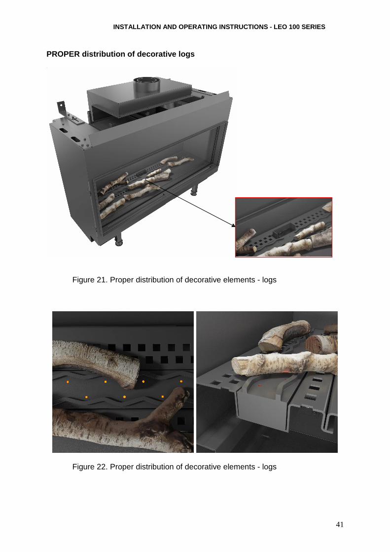
PROPER distribution of decorative logs
Figure 21. Proper distribution of decorative elements - logs
Figure 22. Proper distribution of decorative elements - logs
42
PROPER distribution of decorative stones and logs
Figure 23. Proper distribution of decorative elements - stones with logs
Figure 24. Proper distribution of decorative elements - stones with logs
INSTALLATION AND OPERATING INSTRU CTIONS - LEO 100 SERIES
43
Examples of NOT PROPER distribution of decorative e lements
Figure 25. Not proper distribution of decorative elements
Figure 26. Not proper distribution of decorative elements

Notes ………………………………………………………………………………………………… ………………………………………………………………………………………………… ………………………………………………………………………………………………… ………………………………………………………………………………………………… ………………………………………………………………………………………………… ………………………………………………………………………………………………… ………………………………………………………………………………………………… ………………………………………………………………………………………………… ………………………………………………………………………………………………… ………………………………………………………………………………………………… ………………………………………………………………………………………………… ………………………………………………………………………………………………… ………………………………………………………………………………………………… ………………………………………………………………………………………………… ………………………………………………………………………………………………… ………………………………………………………………………………………………… ………………………………………………………………………………………………… ………………………………………………………………………………………………… ………………………………………………………………………………………………… ………………………………………………………………………………………………… ………………………………………………………………………………………………… ………………………………………………………………………………………………… ………………………………………………………………………………………………… ………………………………………………………………………………………………… ………………………………………………………………………………………………… ………………………………………………………………………………………………… ………………………………………………………………………………………………… ………………………………………………………………………………………………… ………………………………………………………………………………………………… ………………………………………………………………………………………………… ………………………………………………………………………………………………… ………………………………………………………………………………………………… ………………………………………………………………………………………………… ………………………………………………………………………………………………… ………………………………………………………………………………………………… ………………………………………………………………………………………………… ………………………………………………………………………………………………… ………………………………………………………………………………………………… ………………………………………………………………………………………………… ………………………………………………………………………………………………… ………………………………………………………………………………………………… ………………………………………………………………………………………………… ………………………………………………………………………………………………… ………………………………………………………………………………………………… ………………………………………………………………………………………………… …………………………………………………………………………………………………
INSTALLATION AND OPERATING INSTRUCTIONS - LEO 100 SERIES
45
………………………………………………………………………………………………… ………………………………………………………………………………………………… ………………………………………………………………………………………………… ………………………………………………………………………………………………… ………………………………………………………………………………………………… ………………………………………………………………………………………………… ………………………………………………………………………………………………… ………………………………………………………………………………………………… ………………………………………………………………………………………………… ………………………………………………………………………………………………… ………………………………………………………………………………………………… ………………………………………………………………………………………………… ………………………………………………………………………………………………… ………………………………………………………………………………………………… ………………………………………………………………………………………………… ………………………………………………………………………………………………… ………………………………………………………………………………………………… ………………………………………………………………………………………………… ………………………………………………………………………………………………… ………………………………………………………………………………………………… ………………………………………………………………………………………………… ………………………………………………………………………………………………… ………………………………………………………………………………………………… ………………………………………………………………………………………………… ………………………………………………………………………………………………… ………………………………………………………………………………………………… ………………………………………………………………………………………………… ………………………………………………………………………………………………… ………………………………………………………………………………………………… ………………………………………………………………………………………………… ………………………………………………………………………………………………… ………………………………………………………………………………………………… ………………………………………………………………………………………………… ………………………………………………………………………………………………… ………………………………………………………………………………………………… ………………………………………………………………………………………………… ………………………………………………………………………………………………… ………………………………………………………………………………………………… ………………………………………………………………………………………………… ………………………………………………………………………………………………… ………………………………………………………………………………………………… ………………………………………………………………………………………………… ………………………………………………………………………………………………… ………………………………………………………………………………………………… ………………………………………………………………………………………………… ………………………………………………………………………………………………… ………………………………………………………………………………………………… ………………………………………………………………………………………………… ………………………………………………………………………………………………… …………………………………………………………………………………………………

Kratki.pl Marek Bal 4 W. Gombrowicza Street
26-660 Wsola/Jedli ńsk Poland
www.kratki.pl GPS N: 51° 28' 58 ″ , E: 21° 07' 33 ″