installation and operating instructions gen-trans en/d ... · installation and operating...
TRANSCRIPT

ENERGY DIVISION
Installation and Operating InstructionsGEN-TRANS EN/D Automatic Transfer& Switching Unit
ENERGY DIVISION

GEN-TRANS EN/D
AUTOMATIC TRANSFER & SWITCHING UNIT
FOR DIESEL/GAS GENERATORS
Installation & Operating Instructions
Important safety information is contained in this manual. Users must familiarise
themselves with this information before attempting installation or other procedures.
Crompton InstrumentsFreebournes Road
WithamEssex
CM8 3AHEngland
Tel: +44 (0) 1376 509 509Fax: +44 (0) 1376 509 511
E-Mail: [email protected]
ENERGY DIVISION
Crompton Instruments GEN-TRANS EN/D Issue 1 01/2006
Contents Page
1. Introduction 5
2. Installation 7
2.1 Unit Configuration 7
2.2 Mechanical Installation 7
2.1 Front view 8
2.2 Panel cut-out 8
2.3 Side view 8
2.3 Electrical Connections 8
2.4 Rear view. 8
2.5 GEN-TRANS EN/D three phase connections schematic. 9
2.5.1 Unit wiring 11
2.5.2 Unit wiring description 13
3. Definition Of Front Panel And Programming 14
3.2 Programming Procedure 17
3.3 Accessing the Operator Parameters 17
3.3.1 Changing and Saving Operator Parameter Values 19
3.4 Accessing the Technician Parameters 21
3.4.1 Changing and Saving Technician Parameter Values 26
3.5 Programmable function definitions 28
3.6 PC Interface 60
3.6.1 Technical Specifications 60
3.6.2 9 pin D connector/FCC68(4 pin) connection lead 60
3.6.3 Installation Instruction 60
3.6.3.1 Minimum system requirements 60
3.6.3.2 Installing GEN-TRANS EN/D V00/SW 60
3.6.3.3 To Run GEN-TRANS EN/D V00/SW communication software 61
ENERGY DIVISION

Contents Page
3.6.4 Description 62
3.6.4.1 Main Menu 62
File Menu 62
Window Menu 62
Program Menu 63
Observation Menu 64
Operator Parameters Menu 68
Technician Parameters Menu 69
Setting Menu 70
Help Menu 70
4. Commissioning 82
4.1 Manual operation 71
4.2 Auto Operation 72
4.3 Test Mode Operation 72
5. Operation
5.1 Controls and Indicators 73
5.1.1 Alternate Display Description 73
5.1.2 Voltage Display Description 80
5.1.3 Current Display Description 82
5.1.4 Failure Indicators Description 85
5.2 Mode transition 86
5.3 Manual Start 86
5.4 Manual Stop 86
5.5 Auto Operation 86
5.6 Test Operation 87
5.6.1 Exercise Function 87
ENERGY DIVISION
Contents Page
6. Fault Finding 98
6.1 General 88
6.2 Error Messages 88
Table 6.1 Fault finding 90
7. Specifications & Ratings 101
8. Block Diagram 104
9.User Defined Parameter: 105
LIST 105
ENERGY DIVISION

1. Introduction
The GEN-TRANS EN/D provides for automatic transfer of a load from mains to generator in theevent of a mains failure. Intended for unattended operation, it is able to detect failure of anyphase of the mains and to start and switch over to a generator if the mains voltage goes outsidepre-set limits. Both automatic and manual control is possible. A test mode is also availablewhich allows the generator to be run without taking the load.
The unit monitors generator operation and gives warning of any faults that are detected. Theunit monitors:
• Engine speed• Engine Oil pressure• Coolant temperature• Fuel Level• Battery voltage• Charge generator voltage• Engine run time• Number of starts• Next maintenance• Mains volts (L1-N, L2-N, L3-N)• Mains volts (L1-L2, L2-L3, L3-L1)• Mains Hz• Generator volts (L1-N, L2-N, L3-N)• Generator volts (L1-L2, L2-L3, L3-L1)• Generator Hz• Generator kVA• Generator kW• Generator kVAr• Generator pf• Generator kVAh• Generator kWh• Generator kVArh• Load Amps• Earth current (IEA)
It controls:
• Engine fuel supply or engine stopping• Starter motor• Alarm horn• Automatic generator start and load transfer on mains failure• Mains Open, Mains Close, Generator Open and Generator Close contactors
GEN-TRANS EN/D features three three-digit, seven-segment displays, including:
• Load Amps (IL1, IL2, IL3)• Earth current (IEA)
ENERGY DIVISION
5
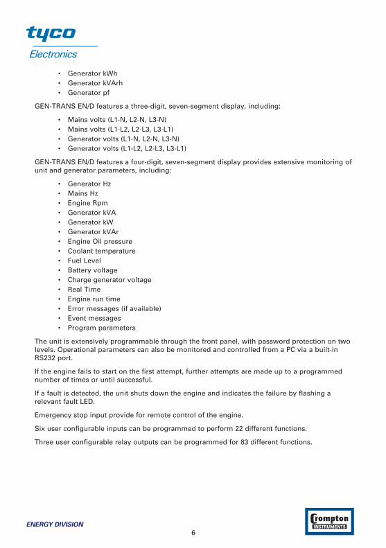
• Generator kWh• Generator kVArh• Generator pf
GEN-TRANS EN/D features a three-digit, seven-segment display, including:
• Mains volts (L1-N, L2-N, L3-N)• Mains volts (L1-L2, L2-L3, L3-L1)• Generator volts (L1-N, L2-N, L3-N)• Generator volts (L1-L2, L2-L3, L3-L1)
GEN-TRANS EN/D features a four-digit, seven-segment display provides extensive monitoring ofunit and generator parameters, including:
• Generator Hz• Mains Hz• Engine Rpm• Generator kVA• Generator kW• Generator kVAr• Engine Oil pressure• Coolant temperature• Fuel Level• Battery voltage• Charge generator voltage• Real Time• Engine run time• Error messages (if available)• Event messages• Program parameters
The unit is extensively programmable through the front panel, with password protection on twolevels. Operational parameters can also be monitored and controlled from a PC via a built-inRS232 port.
If the engine fails to start on the first attempt, further attempts are made up to a programmednumber of times or until successful.
If a fault is detected, the unit shuts down the engine and indicates the failure by flashing arelevant fault LED.
Emergency stop input provide for remote control of the engine.
Six user configurable inputs can be programmed to perform 22 different functions.
Three user configurable relay outputs can be programmed for 83 different functions.
6ENERGY DIVISION
2. Installation
Please read the following information before installing.
A visual inspection of this product for possible damage occurred during shipment
is recommended before installation. It is your responsibility to ensure that qualified
mechanical and electrical technicians install this product.
Before beginning installation of this product:
- Disconnect all electrical power to the machine.
- Make sure the machine cannot operate during installation.
- Follow all safety warnings of the machine manufacturer.
- Read and follow all installation instructions.
2.1 Unit Configuration
The unit can be programmed using the buttons and display on the front panel or GEN-TRANSEN/D software. Refer to Section 3 Definition Of Front Panel And Programming for details.
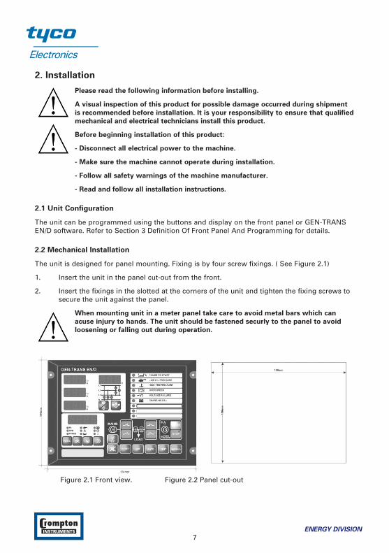
2.2 Mechanical Installation
The unit is designed for panel mounting. Fixing is by four screw fixings. ( See Figure 2.1)
1. Insert the unit in the panel cut-out from the front.
2. Insert the fixings in the slotted at the corners of the unit and tighten the fixing screws to secure the unit against the panel.
When mounting unit in a meter panel take care to avoid metal bars which can
acuse injury to hands. The unit should be fastened securly to the panel to avoid
loosening or falling out during operation.
Figure 2.1 Front view. Figure 2.2 Panel cut-out
ENERGY DIVISION
7

Figure 2.3 Side view.
2.3 Electrical Connections
Figure 2.4 Rear view.
This equipment does not contain any parts and material related to users.
Only qualified personnel and technicians trained specially should work on this
equipment. This equipment contains dangerous voltages and there is severe danger
for human life in the case of unauthorised intervention.
8ENERGY DIVISION
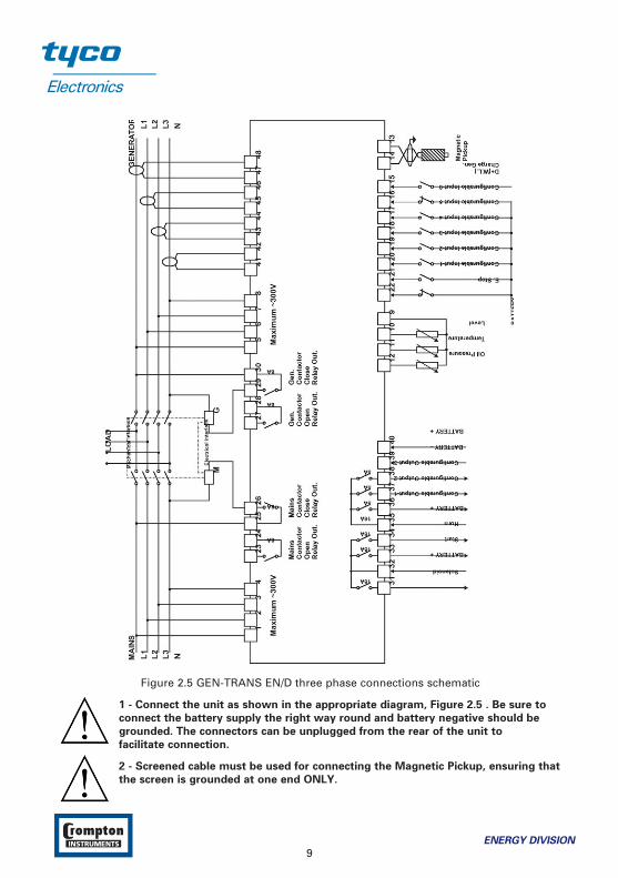
Figure 2.5 GEN-TRANS EN/D three phase connections schematic
1 - Connect the unit as shown in the appropriate diagram, Figure 2.5 . Be sure to
connect the battery supply the right way round and battery negative should be
grounded. The connectors can be unplugged from the rear of the unit to
facilitate connection.
2 - Screened cable must be used for connecting the Magnetic Pickup, ensuring that
the screen is grounded at one end ONLY.
ENERGY DIVISION
9

Table 2.1 shows the connections and recommended cable sizes. Table 2.2 describes thefunctions of the connections.
Table 2.1 Unit wiring
Pin Description Cable Size Notes
(mm2)
1 Mains voltage input (L1) 2,52 Mains voltage input (L2) 2,5 3 phase applications only3 Mains voltage input (L3) 2,5 3 phase applications only4 Mains voltage neutral 2,55 Alternator voltage input (L1) 2,56 Alternator voltage input (L2) 2,5 3 phase applications only7 Alternator voltage input (L3) 2,5 3 phase applications only8 Alternator voltage neutral 2,59 Sender common 1 Connect to sender common10 Fuel level sender 1 Connect to fuel level sender11 Coolant temperature sender 1 Connect to Coolant
temperature sender12 Low oil pressure sender 1 Connect to Low oil pressure sender13 Input from magnetic pick-up 1 Connect to magnetic pick-up device1415 Input from charge generator 1 NC to “0” volt.16 Configurable input-6 1 Switch to “0” volt.17 Configurable input-5 1 Switch to “0” volt.18 Configurable input-4 1 Switch to “0” volt.19 Configurable input-3 1 Switch to “0” volt.20 Configurable input-2 1 Switch to “0” volt.21 Configurable input-1 1 Switch to “0” volt.22 Input from emergency stop 1 NC to “0” volt. When open the
switch on emergency stop.23 Mains Contactor Open Relay Output 2,524 Mains Contactor Open Relay Output 2,525 Mains Contactor Close Relay Output 2,526 Mains Contactor Close Relay Output 2,527 Gen. Contactor Open Relay Output 2,528 Gen. Contactor Open Relay Output 2,529 Gen. Contactor Close Relay Output 2,530 Gen. Contactor Close Relay Output 2,531 Output to fuel / stop solenoid 2,5 16 A. Max.
DC supply from Pin 32
10ENERGY DIVISION
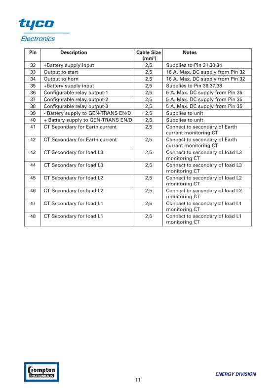
Pin Description Cable Size Notes
(mm2)
32 +Battery supply input 2,5 Supplies to Pin 31,33,3433 Output to start 2,5 16 A. Max. DC supply from Pin 3234 Output to horn 2,5 16 A. Max. DC supply from Pin 3235 +Battery supply input 2,5 Supplies to Pin 36,37,3836 Configurable relay output-1 2,5 5 A. Max. DC supply from Pin 3537 Configurable relay output-2 2,5 5 A. Max. DC supply from Pin 3538 Configurable relay output-3 2,5 5 A. Max. DC supply from Pin 3539 - Battery supply to GEN-TRANS EN/D 2,5 Supplies to unit40 + Battery supply to GEN-TRANS EN/D 2,5 Supplies to unit41 CT Secondary for Earth current 2,5 Connect to secondary of Earth
current monitoring CT42 CT Secondary for Earth current 2,5 Connect to secondary of Earth
current monitoring CT43 CT Secondary for load L3 2,5 Connect to secondary of load L3
monitoring CT44 CT Secondary for load L3 2,5 Connect to secondary of load L3
monitoring CT45 CT Secondary for load L2 2,5 Connect to secondary of load L2
monitoring CT46 CT Secondary for load L2 2,5 Connect to secondary of load L2
monitoring CT47 CT Secondary for load L1 2,5 Connect to secondary of load L1
monitoring CT48 CT Secondary for load L1 2,5 Connect to secondary of load L1
monitoring CT
ENERGY DIVISION
11
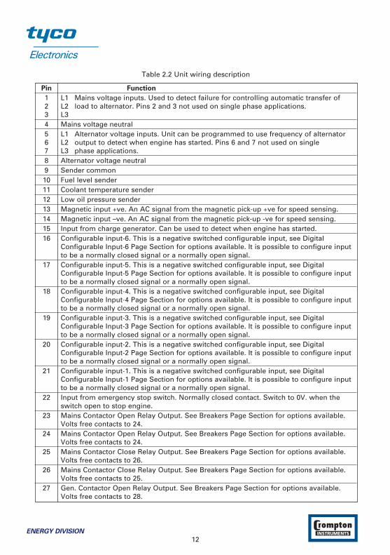
Table 2.2 Unit wiring description
Pin Function
1 L1 Mains voltage inputs. Used to detect failure for controlling automatic transfer of 2 L2 load to alternator. Pins 2 and 3 not used on single phase applications.3 L34 Mains voltage neutral5 L1 Alternator voltage inputs. Unit can be programmed to use frequency of alternator 6 L2 output to detect when engine has started. Pins 6 and 7 not used on single 7 L3 phase applications.8 Alternator voltage neutral9 Sender common10 Fuel level sender11 Coolant temperature sender12 Low oil pressure sender13 Magnetic input +ve. An AC signal from the magnetic pick-up +ve for speed sensing.14 Magnetic input –ve. An AC signal from the magnetic pick-up -ve for speed sensing.15 Input from charge generator. Can be used to detect when engine has started.16 Configurable input-6. This is a negative switched configurable input, see Digital
Configurable Input-6 Page Section for options available. It is possible to configure input to be a normally closed signal or a normally open signal.
17 Configurable input-5. This is a negative switched configurable input, see Digital Configurable Input-5 Page Section for options available. It is possible to configure input to be a normally closed signal or a normally open signal.
18 Configurable input-4. This is a negative switched configurable input, see Digital Configurable Input-4 Page Section for options available. It is possible to configure input to be a normally closed signal or a normally open signal.
19 Configurable input-3. This is a negative switched configurable input, see Digital Configurable Input-3 Page Section for options available. It is possible to configure input to be a normally closed signal or a normally open signal.
20 Configurable input-2. This is a negative switched configurable input, see Digital Configurable Input-2 Page Section for options available. It is possible to configure input to be a normally closed signal or a normally open signal.
21 Configurable input-1. This is a negative switched configurable input, see Digital Configurable Input-1 Page Section for options available. It is possible to configure input to be a normally closed signal or a normally open signal.
22 Input from emergency stop switch. Normally closed contact. Switch to 0V. when the switch open to stop engine.
23 Mains Contactor Open Relay Output. See Breakers Page Section for options available. Volts free contacts to 24.
24 Mains Contactor Open Relay Output. See Breakers Page Section for options available. Volts free contacts to 24.
25 Mains Contactor Close Relay Output. See Breakers Page Section for options available. Volts free contacts to 26.
26 Mains Contactor Close Relay Output. See Breakers Page Section for options available. Volts free contacts to 25.
27 Gen. Contactor Open Relay Output. See Breakers Page Section for options available. Volts free contacts to 28.
12ENERGY DIVISION

Pin Function
28 Gen. Contactor Open Relay Output. See Breakers Page Section for options available. Volts free contacts to 27.
29 Gen. Contactor Close Relay Output. See Breakers Page Section for options available. Volts free contacts to 30.
30 Gen. Contactor Close Relay Output. See Breakers Page Section for options available. Volts free contacts to 29.
31 Output to fuel / stop relay. DC supply from Pin 32. Controls fuel to engine or controls engine stopping.
32 +Battery supply input. Supplies to Pin 31,33,3433 Output to start relay. DC supply from Pin 32. Controls starter motor.34 Output to horn relay. DC supply from Pin 32. Alarm output.35 +Battery supply input. Supplies to Pin 36,37,3836 Configurable relay output-1. DC supply from Pin 35. See Configurable Output-1 Page
Section for options available.37 Configurable relay output-2. DC supply from Pin 35. See Configurable Output-2 Page
Section for options available.38 Configurable relay output-3. DC supply from Pin 35. See Configurable Output-3 Page
Section for options available.39 - Battery input supplies GEN-TRANS EN/D40 + Battery input supplies GEN-TRANS EN/D41 CT Secondary for Earth current (IEA).42 CT Secondary for Earth current (IEA).43 CT Secondary for load L3.44 CT Secondary for load L3.45 CT Secondary for load L2.46 CT Secondary for load L2.47 CT Secondary for load L1.48 CT Secondary for load L1.
ENERGY DIVISION
13
3. Definition Of Front Panel And Programming
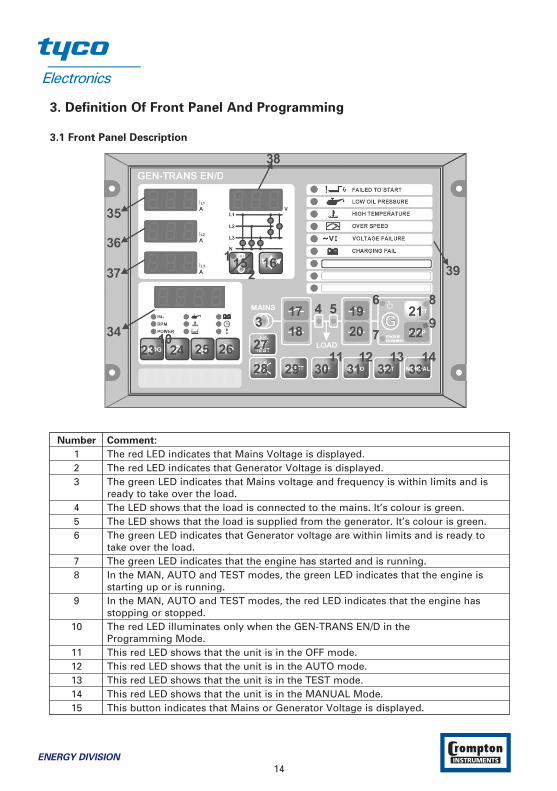
3.1 Front Panel Description
Number Comment:
1 The red LED indicates that Mains Voltage is displayed.2 The red LED indicates that Generator Voltage is displayed.3 The green LED indicates that Mains voltage and frequency is within limits and is
ready to take over the load.4 The LED shows that the load is connected to the mains. It’s colour is green.5 The LED shows that the load is supplied from the generator. It’s colour is green.6 The green LED indicates that Generator voltage are within limits and is ready to
take over the load.7 The green LED indicates that the engine has started and is running.8 In the MAN, AUTO and TEST modes, the green LED indicates that the engine is
starting up or is running. 9 In the MAN, AUTO and TEST modes, the red LED indicates that the engine has
stopping or stopped. 10 The red LED illuminates only when the GEN-TRANS EN/D in the
Programming Mode.11 This red LED shows that the unit is in the OFF mode.12 This red LED shows that the unit is in the AUTO mode.13 This red LED shows that the unit is in the TEST mode.14 This red LED shows that the unit is in the MANUAL Mode.15 This button indicates that Mains or Generator Voltage is displayed.
14ENERGY DIVISION
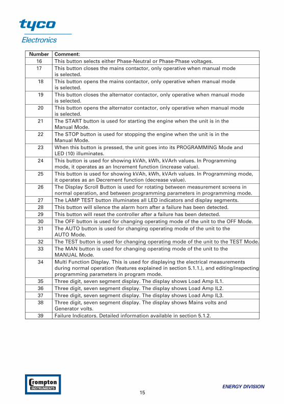
Number Comment:
16 This button selects either Phase-Neutral or Phase-Phase voltages.17 This button closes the mains contactor, only operative when manual mode
is selected.18 This button opens the mains contactor, only operative when manual mode
is selected.19 This button closes the alternator contactor, only operative when manual mode
is selected.20 This button opens the alternator contactor, only operative when manual mode
is selected.21 The START button is used for starting the engine when the unit is in the
Manual Mode.22 The STOP button is used for stopping the engine when the unit is in the
Manual Mode.23 When this button is pressed, the unit goes into its PROGRAMMING Mode and
LED (10) illuminates.24 This button is used for showing kVAh, kWh, kVArh values. In Programming
mode, it operates as an Increment function (increase value).25 This button is used for showing kVAh, kWh, kVArh values. In Programming mode,
it operates as an Decrement function (decrease value).26 The Display Scroll Button is used for rotating between measurement screens in
normal operation, and between programming parameters in programming mode.27 The LAMP TEST button illuminates all LED indicators and display segments.28 This button will silence the alarm horn after a failure has been detected.29 This button will reset the controller after a failure has been detected.30 The OFF button is used for changing operating mode of the unit to the OFF Mode.31 The AUTO button is used for changing operating mode of the unit to the
AUTO Mode.32 The TEST button is used for changing operating mode of the unit to the TEST Mode.33 The MAN button is used for changing operating mode of the unit to the
MANUAL Mode.34 Multi Function Display. This is used for displaying the electrical measurements
during normal operation (features explained in section 5.1.1.), and editing/inspectingprogramming parameters in program mode.
35 Three digit, seven segment display. The display shows Load Amp IL1.36 Three digit, seven segment display. The display shows Load Amp IL2.37 Three digit, seven segment display. The display shows Load Amp IL3.38 Three digit, seven segment display. The display shows Mains volts and
Generator volts.39 Failure Indicators. Detailed information available in section 5.1.2.
ENERGY DIVISION
15
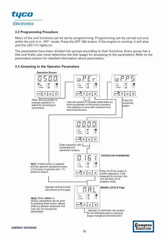
3.2 Programming Procedure
Many of the unit functions can be set by programming. Programming can be carried out onlywhile the unit is in OFF mode. Press the OFF (30) button. If the engine is running, it will stopand the LED (11) lights on.
The parameters have been divided into groups according to their functions. Every group has atitle and firstly user must determine the title (page) for accessing to the parameters. Refer to theparameters section for detailed information about parameters.
3.3 Accessing to the Operator Parameters
16ENERGY DIVISION

ENERGY DIVISION
17
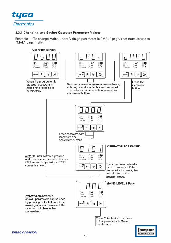
3.3.1 Changing and Saving Operator Parameter Values
Example-1 : To change Mains Under Voltage parameter in ”MAL” page, user must access to“MAL” page firstly.
18ENERGY DIVISION

ENERGY DIVISION
19
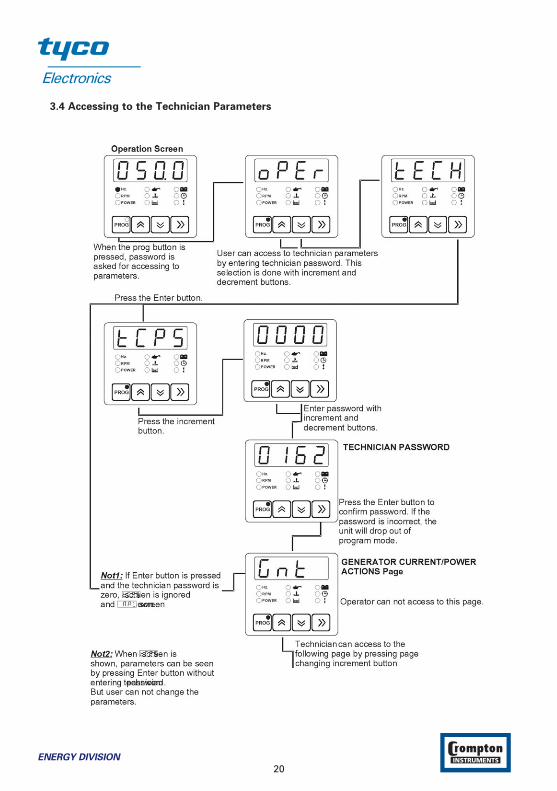
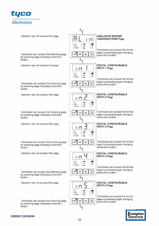
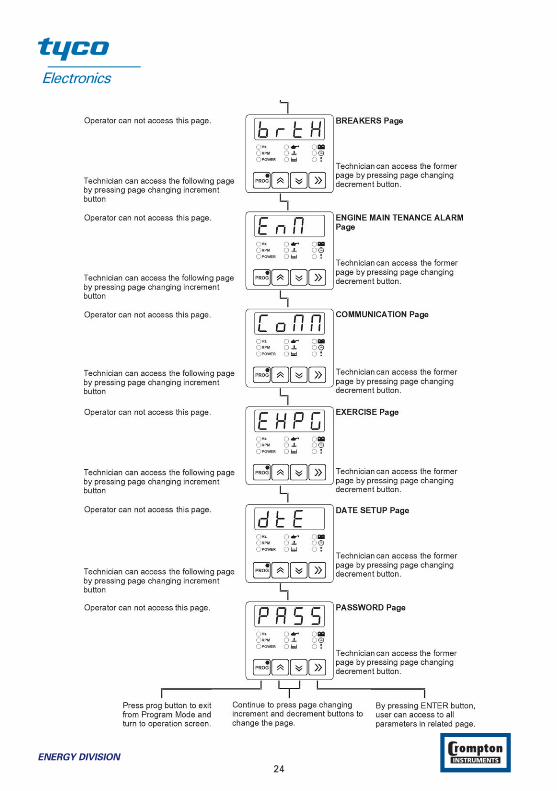
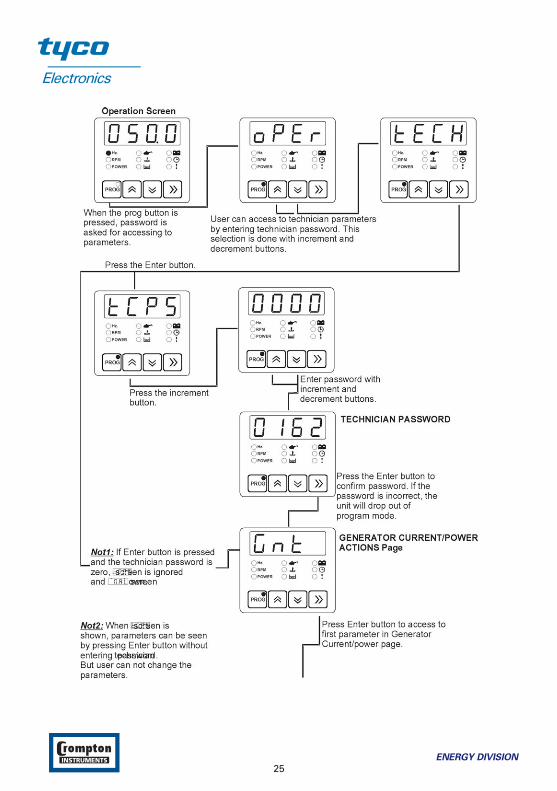
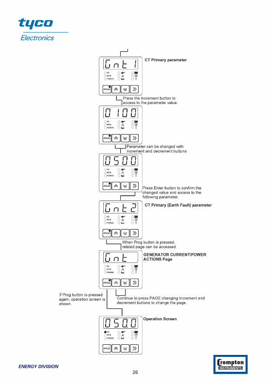
3.4 Accessing to the Technician Parameters
20ENERGY DIVISION

ENERGY DIVISION
21
22ENERGY DIVISION

ENERGY DIVISION
23
24ENERGY DIVISION
ENERGY DIVISION
25
26ENERGY DIVISION

3.5 Programmable function definitions
Operator parameters
(mAL) MAINS LEVELS page
mA1 MAINS UNDER VOLTAGE VAC 60 – 600 320mA2 MAINS UNDER VOLTAGE RETURN VAC 60 – 600 340mA3 MAINS OVER VOLTAGE VAC 60 – 600 440mA4 MAINS OVER VOLTAGE RETURN VAC 60 – 600 420mA5 MAINS UNDER FREQUENCY Hz 30.0 – 75.0 45.0mA6 MAINS UNDER FREQUENCY RETURN Hz 30.0 – 75.0 48.0mA7 MAINS OVER FREQUENCY Hz 30.0 – 75.0 55.0mA8 MAINS OVER FREQUENCY RETURN Hz 30.0 – 75.0 52.0
The unit uses these parameters to decide when to lit the “Mains Okey LED”.In Automatic mode, the unit uses these parameters to switch the load between the mains supplyand the alternator.
(GnU) GENERATOR VOLTAGE LEVELS page
GnU1 GENERATOR UNDER VOLTAGE VAC (dis)60 – 600 320GnU2 GENERATOR UNDER VOLTAGE PRE-ALARM VAC (dis)60 – 600 340GnU3 GENERATOR LOADING VOLTAGE VAC 60 – 600 345GnU4 GENERATOR OVER VOLTAGE PRE-ALARM VAC (dis)60 – 600 420GnU5 GENERATOR OVER VOLTAGE PRE-ALARM RETURN VAC 60 – 600 400GnU6 GENERATOR OVER VOLTAGE SHUTDOWN VAC 60 – 600 440
The unit uses these parameters to decide when to display Voltage Failure and Voltage ErrorMessages. Also, the unit uses Generator Loading Voltage parameter to decide when to take theload.
(GnF) GENERATOR FREQUENCY LEVELS page
GnF1 GENERATOR UNDER FREQUENCY Hz (dis)30.0 – 75.0 43.0GnF2 GENERATOR UNDER FREQUENCY PRE-ALARM Hz (dis)30.0 – 75.0 45.0GnF3 GENERATOR LOADING FREQUENCY Hz 30.0 – 75.0 46.0GnF4 GENERATOR OVER FREQUENCY PRE-ALARM Hz (dis)30.0 – 75.0 55.0GnF5 GENERATOR OVER FRQ PRE-ALARM RETURN Hz 30.0 – 75.0 54.0GnF6 GENERATOR OVER FREQUENCY SHUTDOWN Hz (dis)30.0 – 75.0 58.0
The unit uses these parameters to decide when to display Speed Failure and Frequency ErrorMessages. Also, the unit uses Generator Loading Frequency parameter to decide when to takethe load.
(Gno) GENERATOR CURRENT/POWER LEVELS page
Gno1 GENERATOR OVER CURRENT A AC 0 – 999 999Gno2 GENERATOR SHORT CIRCUIT A AC 0 – 999 999Gno3 GENERATOR EARTH FAULT A AC 0 – 999 100Gno4 GENERATOR MINIMUM ACTIVE POWER kW 0 - 999 50
ENERGY DIVISION
27
Technician parameters
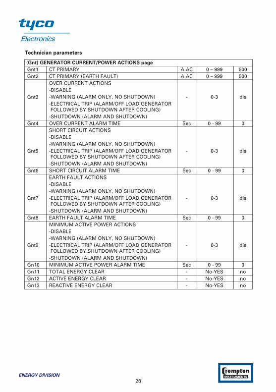
(Gnt) GENERATOR CURRENT/POWER ACTIONS page
Gnt1 CT PRIMARY A AC 0 – 999 500Gnt2 CT PRIMARY (EARTH FAULT) A AC 0 – 999 500
OVER CURRENT ACTIONS-DISABLE
Gnt3 -WARNING (ALARM ONLY, NO SHUTDOWN) - 0-3 dis-ELECTRICAL TRIP (ALARM/OFF LOAD GENERATOR FOLLOWED BY SHUTDOWN AFTER COOLING)
-SHUTDOWN (ALARM AND SHUTDOWN)Gnt4 OVER CURRENT ALARM TIME Sec 0 - 99 0
SHORT CIRCUIT ACTIONS-DISABLE-WARNING (ALARM ONLY, NO SHUTDOWN)
Gnt5 -ELECTRICAL TRIP (ALARM/OFF LOAD GENERATOR - 0-3 dis FOLLOWED BY SHUTDOWN AFTER COOLING)
-SHUTDOWN (ALARM AND SHUTDOWN)Gnt6 SHORT CIRCUIT ALARM TIME Sec 0 - 99 0
EARTH FAULT ACTIONS-DISABLE-WARNING (ALARM ONLY, NO SHUTDOWN)
Gnt7 -ELECTRICAL TRIP (ALARM/OFF LOAD GENERATOR - 0-3 dis FOLLOWED BY SHUTDOWN AFTER COOLING)
-SHUTDOWN (ALARM AND SHUTDOWN)Gnt8 EARTH FAULT ALARM TIME Sec 0 - 99 0
MINIMUM ACTIVE POWER ACTIONS-DISABLE-WARNING (ALARM ONLY, NO SHUTDOWN)
Gnt9 -ELECTRICAL TRIP (ALARM/OFF LOAD GENERATOR - 0-3 dis FOLLOWED BY SHUTDOWN AFTER COOLING)
-SHUTDOWN (ALARM AND SHUTDOWN)Gn10 MINIMUM ACTIVE POWER ALARM TIME Sec 0 - 99 0Gn11 TOTAL ENERGY CLEAR - No-YES noGn12 ACTIVE ENERGY CLEAR - No-YES noGn13 REACTIVE ENERGY CLEAR - No-YES no
28ENERGY DIVISION
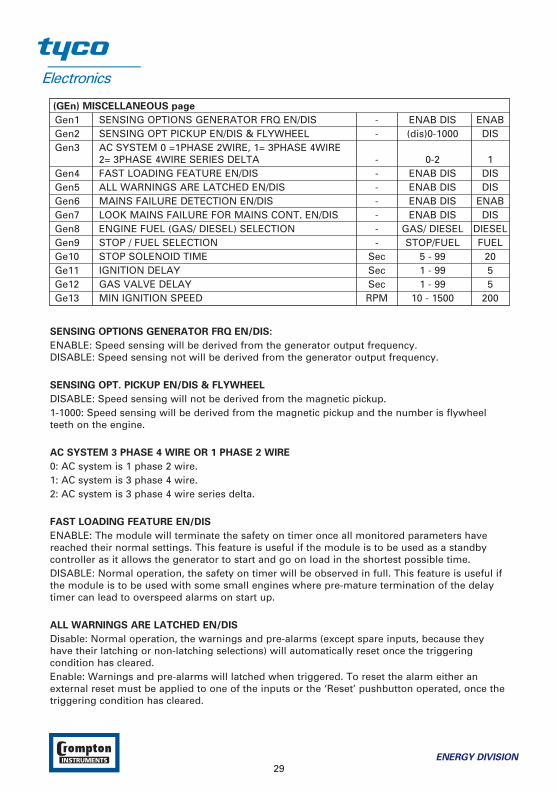
(GEn) MISCELLANEOUS page
Gen1 SENSING OPTIONS GENERATOR FRQ EN/DIS - ENAB DIS ENABGen2 SENSING OPT PICKUP EN/DIS & FLYWHEEL - (dis)0-1000 DISGen3 AC SYSTEM 0 =1PHASE 2WIRE, 1= 3PHASE 4WIRE
2= 3PHASE 4WIRE SERIES DELTA - 0-2 1Gen4 FAST LOADING FEATURE EN/DIS - ENAB DIS DISGen5 ALL WARNINGS ARE LATCHED EN/DIS - ENAB DIS DISGen6 MAINS FAILURE DETECTION EN/DIS - ENAB DIS ENABGen7 LOOK MAINS FAILURE FOR MAINS CONT. EN/DIS - ENAB DIS DISGen8 ENGINE FUEL (GAS/ DIESEL) SELECTION - GAS/ DIESEL DIESELGen9 STOP / FUEL SELECTION - STOP/FUEL FUELGe10 STOP SOLENOID TIME Sec 5 - 99 20Ge11 IGNITION DELAY Sec 1 - 99 5Ge12 GAS VALVE DELAY Sec 1 - 99 5Ge13 MIN IGNITION SPEED RPM 10 - 1500 200
SENSING OPTIONS GENERATOR FRQ EN/DIS:
ENABLE: Speed sensing will be derived from the generator output frequency.DISABLE: Speed sensing not will be derived from the generator output frequency.
SENSING OPT. PICKUP EN/DIS & FLYWHEEL
DISABLE: Speed sensing will not be derived from the magnetic pickup.1-1000: Speed sensing will be derived from the magnetic pickup and the number is flywheelteeth on the engine.
AC SYSTEM 3 PHASE 4 WIRE OR 1 PHASE 2 WIRE
0: AC system is 1 phase 2 wire.1: AC system is 3 phase 4 wire.2: AC system is 3 phase 4 wire series delta.
FAST LOADING FEATURE EN/DIS
ENABLE: The module will terminate the safety on timer once all monitored parameters havereached their normal settings. This feature is useful if the module is to be used as a standbycontroller as it allows the generator to start and go on load in the shortest possible time.DISABLE: Normal operation, the safety on timer will be observed in full. This feature is useful ifthe module is to be used with some small engines where pre-mature termination of the delaytimer can lead to overspeed alarms on start up.
ALL WARNINGS ARE LATCHED EN/DIS
Disable: Normal operation, the warnings and pre-alarms (except spare inputs, because theyhave their latching or non-latching selections) will automatically reset once the triggeringcondition has cleared.Enable: Warnings and pre-alarms will latched when triggered. To reset the alarm either anexternal reset must be applied to one of the inputs or the ‘Reset’ pushbutton operated, once thetriggering condition has cleared.
ENERGY DIVISION
29

MAINS FAILURE DETECTION EN/DIS
Disable: The module will not monitor the AC mains supply for failure. The AC mainsinstrumentation will still be active however.Enable: The module will monitor the incoming AC mains supply. Should the supply go out sideof limits the module will initiate its automatic mains failure sequence.
LOOK MAINS FAILURE FOR MAINS CONTACTOR EN/DIS
Disable: In the event of a mains failure the Gentrans En/d will attempt to maintain the supply tothe load for the incoming AC mains supply until the generator is available to go on load. In theevent of a generator failure the module will default back to the incoming AC mains supply. Thisprovides a ‘fail-safe system’, ensuring that in the event of a system failure the load will still befed from the AC mains supply.Enable: As soon as the module detects a mains failure the mains contactor or breaker relay willbe opened to remove the supply from the load. This is to prevent damage to the load in case ofsingle-phase failure, especially useful if the load is a 3-phase motor or pump. The supply to theload will then be fed from the gen-set once it is available. In the event of generator failure themodule will open the generator relay and remove the supply to the load until either the mainssupply is restored or the generator is restarted.
ENGINE FUEL (DIESEL /GAS) SELECTION
Diesel or Gas engine can be selected.If diesel engine selected:
STOP/FUEL SELECTION
Selection for the engine has Fuel or Stop selenoid.
STOP SOLEONID TIME
This timer is used if the unit is confgured to operate an Energise to stop engine. It dictates theduration that the Stop Solenoid output will remain active after the module has detected
the engine has come to rest. If the Stop Solenoid output is not configured, this timer will stilloperate, preventing an immediate restart.Example: Start/stop diagram for Diesel Engine.
The formula signs and indices mean:TPT Preheating time [s]TCT Engagement time [s]TRT Interval between 2 start attempts [s]TDT Engine delayed monitoring [s]
30ENERGY DIVISION
ENERGY DIVISION
31

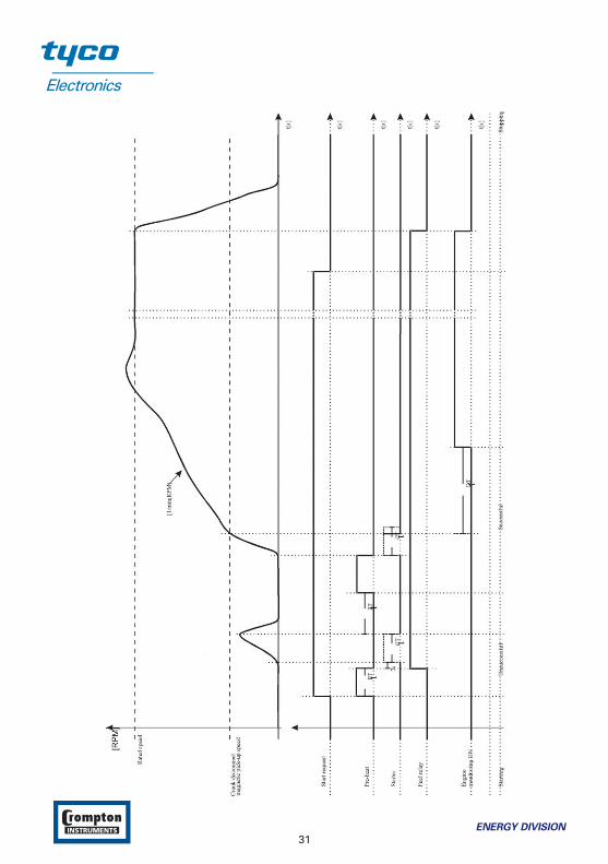
If gas engine selected:
IGNITION DELAY
With gas engines often purging operation is desired before starting. With the engaging of thestarter the ignition delay is started. If the ‘min ignition speed’ is reached after expiry of this time,the configurable relay output ‘ignition’ is set.
GAS VALVE DELAY
By setting the ignition relay the gas valve delay is started. After the expiry of the here set timeas long as the number of revolutions is higher than the minimum ignition speed, the gas valveis set. With the reaching of the ignition speed the configurable relay output ‘ignition’ is sealinguntil shutdown of the engine.
MIN IGNITION SPEED
After expiry of the ignition delay the number of revolutions set here must be reached at least, sothat the configurable relay output ‘ignition’ will be set.
Example: Start/stop diagram for Gas Engine.
The formula signs and indices mean:
TRT Interval between 2 start attempts [s]
TIT Ignition delay [s]
TGT Gas valve delay [s]
TDT Engine delayed monitoring [s]
32ENERGY DIVISION

ENERGY DIVISION
33

(EnSt) ENGINE STARTING OPTIONS page
EnS1 AUDIBLE ALARM PRIOR TO STARTING EN/DIS - ENAB DIS DISEnS2 NUMBER OF START ATTEMPTS - 1 – 10 3EnS3 CRANKING TIME SEC 5 – 99 5EnS4 CRANK REST TIME SEC 5 – 99 10EnS5 MULTIPLE START ENGAGE ATTEMPTS E/D (PICK) - ENAB DIS DISEnS6 ENGAGE ATTEMPT TIME (PICKUP) SEC 0.1 – 10.0 1.0EnS7 ENGAGE ATTEMPT REST TIME (PICKUP) SEC 0.1 – 10.0 1.0EnS8 PICKUP SENSOR FAIL DELAY(PICKUP) SEC 0.1 – 10.0 1.0
AUDIBLE ALARM PRIOR TO STARTING EN/DIS
ENABLE: The audible alarm will sound before the engine starts. The sounder will become activeonce the start delay is initialised, it will remain active until either the engine reaches crankdisconnect speed or pre-heat timers are cancelled.
NUMBER OF START ATTEMPTS
This value is the number of times the module will attempt to start the generator. Should thegenerator start the module will not attempt further starts. If the generator does not start after thefinal attempt, the module will give a ‘Fail to start’ alarm.
CRANKING TIME
This is the maximum amount of time that the module will energise the starter motor for duringstarting attempts once the starter has engaged.
CRANK REST TIME
This is the amount of time the module will wait for between start attempts. This is to allow thestarter motor to cool and the starter batteries to recover.
MULTIPLE START ENGAGE ATTEMPTS E/D
(Only available if using Magnetic pickup)
ENABLE: The module will monitor the flywheel to ensure that the starter motor has engaged. Ifit detects the starter has not meshed, it will de-energise the start relay and after a short delay itwill attempt to re-engage the starter. This will be repeated until either the starter motor engagescorrectly or the number of engage attempts expires. Each start attempt can have a maximumnumber of attempts to engage the starter, this value is entered the box.DISABLE: Normal operation, starter engagement with flywheel will not monitored.
ENGAGE ATTEMPT TIME
(Only available if using Magnetic pickup and multiple engage attempts)
This timer dictates the duration that the module will attempt to engage the starter motor duringeach engage attempt. If the magnetic pickup is not detecting movement of the flywheel whenthis timer expires the engage attempt will terminate. Once all engage attempts have been madethe module will generate ‘Fail to engage’ alarm.
34ENERGY DIVISION

ENGAGE ATTEMPT REST TIME
(Only available if using Magnetic pickup and multiple engage attempts)
This timer dictates the duration that the module will wait between attempts to engage thestarter.
PICKUP SENSOR FAIL DELAY
(Only available if using Magnetic pickup without multiple engage attempts)
This is only used if magnetic pickup speed sensing is selected. When cranking, the module mustreceive a speed signal within this time. If no signal is present the generator will be shutdownand Loss of Speed Sensing alarm given.
(EnC) ENGINE CRANK DISCONNECT page
EnC1 CRANK DISCONNECT ON GEN. FREQUENCY Hz 25.0 – 75.0 30.0EnC2 CRANK DISCONNECT ON MAGNETIC PICKUP RPM 500-6000 500EnC3 CRANK DISCONNECT ON GEN. VOLTAGE VAC (dis)60 – 600 300EnC4 CRANK DISCONNECT ON CHARGE ALT. VOLTAGE VDC (dis)6.0 – 30.0 disEnC5 CRANK DISCONNECT ON OIL PRESSURE BAR (dis)1.0-90.0 1.5
(GnS) GENERATOR SPEED SETTINGS page
GnS1 GENERATOR UNDER SPEED RPM (dis)500 – 5000 1270GnS2 GENERATOR UNDER SPEED PREALARM RPM (dis) 500 – 5000 1350GnS3 GENERATOR UNDER SPEED PREALARM RETURN RPM 500 – 5000 1380GnS4 GENERATOR OVER SPEED PREALARM RPM (dis) 500 – 5000 1650GnS5 GENERATOR OVER SPEED PREALARM RETURN RPM 500 – 5000 1620GnS6 GENERATOR OVER SPEED SHUTDOWN RPM 500 – 5000 1740
(EnbA) ENGINE PLANT BATTERY page
Enb1 BATTERY UNDERVOLTS WARNING VDC (dis)6.0 – 30.0 10.0Enb2 BATTERY UNDERVOLTS WARNING RETURN VDC 6.0 – 30.0 10.5Enb3 BATT UNDERVOLTS VOLTS DELAY Sec 0 – 9.9 1.0Enb4 BATTERY OVERVOLTS WARNING VDC (dis)6.0 – 30.0 30.0Enb5 BATTERY OVERVOLTS WARNING RETURN VDC 6.0 – 30.0 29.5Enb6 BATT OVERVOLTS DELAY sec 0 – 9.9 1.0Enb7 CHARGE ALTERNATOR WARNING VDC (dis)6.0 – 30.0 dis
ENERGY DIVISION
35

(Aın) ANALOGUE INPUTS page
Aın1 OIL PRESSURE INPUT TYPE Dis,no,nc,anlg ANLGAın2 OIL PRESSURE PRE-ALARM BAR (dis)0.0 – 99.9 1.2Aın3 OIL PRESSURE PRE-ALARM RETURN BAR 0.0 – 99.9 1.4Aın4 OIL PRESSURE SHUTDOWN BAR 0.0 – 99.9 1.0Aın5 TEMPERATURE INPUT TYPE Dis,no,nc,anlg ANLGAın6 TEMPERATURE PRE-ALARM C (dis)0 - 300 90Aın7 TEMPERATURE PRE-ALARM RETURN C 0 - 300 88Aın8 TEMPERATURE SHUTDOWN C 0 - 300 95Aın9 LEVEL PRE-ALARM L (dis)0 - 300 100Aı10 LEVEL PRE-ALARM RETURN L 0 - 300 110Aı11 LEVEL SHUTDOWN L 0 - 300 90
OIL PRESSURE INPUT TYPE
This section is used to configure the Oil Pressure sender input.dıS: The Oil Pressure input will not be monitored.1: digital & closed for low oil pressure: The Oil pressure input is fed from an engine mounteddigital pressure switch. This switch returns a closed signal during low oil pressure conditions(and engine at rest), once oil pressure is established the switch will open.2: digital & open for low oil pressure: The Oil pressure input is fed from an engine mounteddigital pressure switch. This switch returns an open signal during low oil pressure conditions(and engine at rest), once oil pressure is established the switch will close.3: analog: The Oil pressure input is connected to a resistive type engine mounted oil pressuretransducer.
TEMPERATURE INPUT TYPE
This section is used to configure the Coolant Temperature sender input.dıS: The Coolant Temperature input will not be monitored.1: digital & normally closed: The Coolant Temperature input is fed from an engine mounteddigital temperature switch. This switch returns a closed signal during low temperature, shouldthe temperature rise above the switch manifacturers trip point the switch contact will open.2: digital & normally open: The Coolant Temperature input is fed from an engine mounteddigital temperature switch. This switch returns an open signal during low temperature, shouldthe temperature rise above the switch manifacturers trip point the switch contact will close.3: analog: The Oil pressure input is connected to a resistive type engine mounted temperaturetransducer.
36ENERGY DIVISION
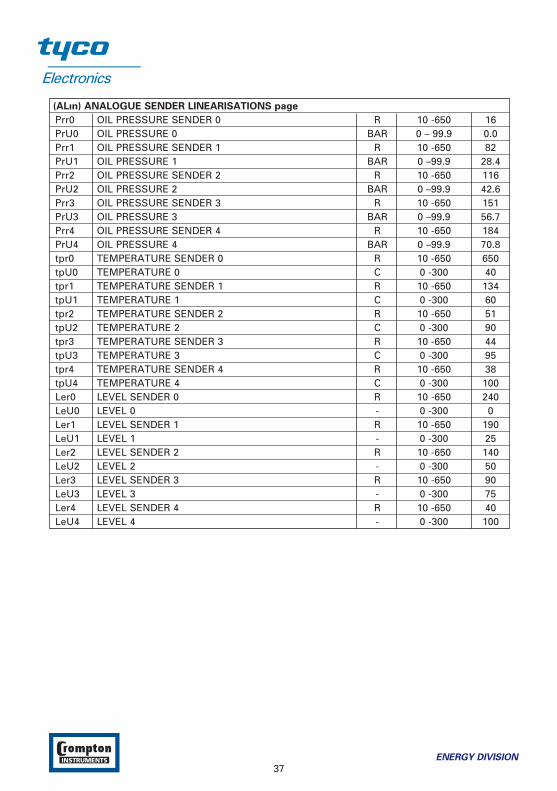
(ALın) ANALOGUE SENDER LINEARISATIONS page
Prr0 OIL PRESSURE SENDER 0 R 10 -650 16PrU0 OIL PRESSURE 0 BAR 0 – 99.9 0.0Prr1 OIL PRESSURE SENDER 1 R 10 -650 82PrU1 OIL PRESSURE 1 BAR 0 –99.9 28.4Prr2 OIL PRESSURE SENDER 2 R 10 -650 116PrU2 OIL PRESSURE 2 BAR 0 –99.9 42.6Prr3 OIL PRESSURE SENDER 3 R 10 -650 151PrU3 OIL PRESSURE 3 BAR 0 –99.9 56.7Prr4 OIL PRESSURE SENDER 4 R 10 -650 184PrU4 OIL PRESSURE 4 BAR 0 –99.9 70.8tpr0 TEMPERATURE SENDER 0 R 10 -650 650tpU0 TEMPERATURE 0 C 0 -300 40tpr1 TEMPERATURE SENDER 1 R 10 -650 134tpU1 TEMPERATURE 1 C 0 -300 60tpr2 TEMPERATURE SENDER 2 R 10 -650 51tpU2 TEMPERATURE 2 C 0 -300 90tpr3 TEMPERATURE SENDER 3 R 10 -650 44tpU3 TEMPERATURE 3 C 0 -300 95tpr4 TEMPERATURE SENDER 4 R 10 -650 38tpU4 TEMPERATURE 4 C 0 -300 100Ler0 LEVEL SENDER 0 R 10 -650 240LeU0 LEVEL 0 - 0 -300 0Ler1 LEVEL SENDER 1 R 10 -650 190LeU1 LEVEL 1 - 0 -300 25Ler2 LEVEL SENDER 2 R 10 -650 140LeU2 LEVEL 2 - 0 -300 50Ler3 LEVEL SENDER 3 R 10 -650 90LeU3 LEVEL 3 - 0 -300 75Ler4 LEVEL SENDER 4 R 10 -650 40LeU4 LEVEL 4 - 0 -300 100
ENERGY DIVISION
37

(ın1) DIGITAL CONFIGURABLE INPUT (1) page
ın11 DISABLE, USER CONFIGURED OR SELECT FROM LIST (dis)0 - 2 1ın12 IF USER CONFIGURED
-POLARITY (CLOSE TO ACTIVATE, OPEN TO ACTIVATE) 0 - 1 0ın13 IF USER CONFIGURED
-INDICATION(STATUS, WARNING NON-LATCHING, WARNING LATCHING, ELECTRICAL TRIP, SHUTDOWN) 0 – 4 0
ın14 IF USER CONFIGURED-ACTIVATION (ACTIVE FROM STARTING, ACTIVE FROM SAFETY ON, ALWAYS ACTIVE) 0 – 2 0IF SELECT FROM LIST0 REMOTE START1 AUXILIARY MAINS FAIL2 SIMULATE LAMP TEST BUTTON3 SIMULATE HORN RESET BUTTON4 SIMULATE ALARM RESET BUTTON5 SIMULATE OFF BUTTON6 SIMULATE AUTO BUTTON7 SIMULATE TEST BUTTON8 SIMULATE MANUAL BUTTON9 SIMULATE START BUTTON10 SIMULATE STOP BUTTON
ın15 11 GENERATOR CLOSED AUXILIARY 0 – 21 212 GENERATOR LOAD INHIBIT13 MAINS CLOSED AUXILIARY14 MAINS LOAD INHIBIT15 AUTO RESTORE INHIBIT16 AUTO START INHIBIT17 PANEL LOCK18 SCHEDULED RUNS INHIBITED19 RESET MAINTENANCE ALARM20 TRANSFER TO GENERATOR/OPEN MAINS21 TRANSFER TO MAINS/OPEN GENERATOR
38ENERGY DIVISION

(ın2) DIGITAL CONFIGURABLE INPUT (2) page
ın21 DISABLE, USER CONFIGURED OR SELECT FROM LIST (dis)0 - 2 1ın22 IF USER CONFIGURED
-POLARITY (CLOSE TO ACTIVATE, OPEN TO ACTIVATE) 0 - 1 0ın23 IF USER CONFIGURED
-INDICATION(STATUS, WARNING NON-LATCHING, WARNING LATCHING, ELECTRICAL TRIP, SHUTDOWN) 0 – 4 0
ın24 IF USER CONFIGURED-ACTIVATION (ACTIVE FROM STARTING, ACTIVE FROM SAFETY ON, ALWAYS ACTIVE) 0 – 2 0IF SELECT FROM LIST0 REMOTE START1 AUXILIARY MAINS FAIL2 SIMULATE LAMP TEST BUTTON3 SIMULATE HORN RESET BUTTON4 SIMULATE ALARM RESET BUTTON5 SIMULATE OFF BUTTON6 SIMULATE AUTO BUTTON7 SIMULATE TEST BUTTON8 SIMULATE MANUAL BUTTON9 SIMULATE START BUTTON10 SIMULATE STOP BUTTON
ın25 11 GENERATOR CLOSED AUXILIARY 0 – 21 312 GENERATOR LOAD INHIBIT13 MAINS CLOSED AUXILIARY14 MAINS LOAD INHIBIT15 AUTO RESTORE INHIBIT16 AUTO START INHIBIT17 PANEL LOCK18 SCHEDULED RUNS INHIBITED19 RESET MAINTENANCE ALARM20 TRANSFER TO GENERATOR/OPEN MAINS21 TRANSFER TO MAINS/OPEN GENERATOR
ENERGY DIVISION
39

(ın3) DIGITAL CONFIGURABLE INPUT (3) page
ın31 DISABLE, USER CONFIGURED OR SELECT FROM LIST (dis)0 - 2 1ın32 IF USER CONFIGURED
-POLARITY (CLOSE TO ACTIVATE, OPEN TO ACTIVATE) 0 - 1 0ın33 IF USER CONFIGURED
-INDICATION(STATUS, WARNING NON-LATCHING, WARNING LATCHING, ELECTRICAL TRIP, SHUTDOWN) 0 – 4 0
ın34 IF USER CONFIGURED-ACTIVATION (ACTIVE FROM STARTING, ACTIVE FROM SAFETY ON, ALWAYS ACTIVE) 0 – 2 0IF SELECT FROM LIST0 REMOTE START1 AUXILIARY MAINS FAIL2 SIMULATE LAMP TEST BUTTON3 SIMULATE HORN RESET BUTTON4 SIMULATE ALARM RESET BUTTON5 SIMULATE OFF BUTTON6 SIMULATE AUTO BUTTON7 SIMULATE TEST BUTTON8 SIMULATE MANUAL BUTTON9 SIMULATE START BUTTON10 SIMULATE STOP BUTTON
ın35 11 GENERATOR CLOSED AUXILIARY 0 – 21 412 GENERATOR LOAD INHIBIT13 MAINS CLOSED AUXILIARY14 MAINS LOAD INHIBIT15 AUTO RESTORE INHIBIT16 AUTO START INHIBIT17 PANEL LOCK18 SCHEDULED RUNS INHIBITED19 RESET MAINTENANCE ALARM20 TRANSFER TO GENERATOR/OPEN MAINS21 TRANSFER TO MAINS/OPEN GENERATOR
40ENERGY DIVISION
(ın4) DIGITAL CONFIGURABLE INPUT (4) page
ın41 DISABLE, USER CONFIGURED OR SELECT FROM LIST (dis)0 - 2 1ın42 IF USER CONFIGURED
-POLARITY (CLOSE TO ACTIVATE, OPEN TO ACTIVATE) 0 - 1 0ın43 IF USER CONFIGURED
-INDICATION(WARNING NON-LATCHING, WARNING LATCHING, ELECTRICAL TRIP, SHUTDOWN) 1 – 4 1
ın44 IF USER CONFIGURED-ACTIVATION (ACTIVE FROM STARTING, ACTIVE FROM SAFETY ON, ALWAYS ACTIVE) 0 – 2 0IF SELECT FROM LIST0 REMOTE START1 AUXILIARY MAINS FAIL2 SIMULATE LAMP TEST BUTTON3 SIMULATE HORN RESET BUTTON4 SIMULATE ALARM RESET BUTTON5 SIMULATE OFF BUTTON6 SIMULATE AUTO BUTTON7 SIMULATE TEST BUTTON8 SIMULATE MANUAL BUTTON9 SIMULATE START BUTTON
ın45 10 SIMULATE STOP BUTTON 0 – 21 511 GENERATOR CLOSED AUXILIARY12 GENERATOR LOAD INHIBIT13 MAINS CLOSED AUXILIARY14 MAINS LOAD INHIBIT15 AUTO RESTORE INHIBIT16 AUTO START INHIBIT17 PANEL LOCK18 SCHEDULED RUNS INHIBITED19 RESET MAINTENANCE ALARM20 TRANSFER TO GENERATOR/OPEN MAINS21 TRANSFER TO MAINS/OPEN GENERATOR
ENERGY DIVISION
41
(ın5) DIGITAL CONFIGURABLE INPUT (5) page
ın51 DISABLE, USER CONFIGURED OR SELECT FROM LIST (dis)0 - 2 1ın52 IF USER CONFIGURED
-POLARITY (CLOSE TO ACTIVATE, OPEN TO ACTIVATE) 0 - 1 0ın53 IF USER CONFIGURED
-INDICATION(WARNING NON-LATCHING, WARNING LATCHING, ELECTRICAL TRIP, SHUTDOWN) 1 – 4 1
ın54 IF USER CONFIGURED-ACTIVATION (ACTIVE FROM STARTING, ACTIVE FROM SAFETY ON, ALWAYS ACTIVE) 0 – 2 0IF SELECT FROM LIST0 REMOTE START1 AUXILIARY MAINS FAIL2 SIMULATE LAMP TEST BUTTON3 SIMULATE HORN RESET BUTTON4 SIMULATE ALARM RESET BUTTON5 SIMULATE OFF BUTTON6 SIMULATE AUTO BUTTON7 SIMULATE TEST BUTTON8 SIMULATE MANUAL BUTTON9 SIMULATE START BUTTON
ın55 10 SIMULATE STOP BUTTON 0 – 21 611 GENERATOR CLOSED AUXILIARY12 GENERATOR LOAD INHIBIT13 MAINS CLOSED AUXILIARY14 MAINS LOAD INHIBIT15 AUTO RESTORE INHIBIT16 AUTO START INHIBIT17 PANEL LOCK18 SCHEDULED RUNS INHIBITED19 RESET MAINTENANCE ALARM20 TRANSFER TO GENERATOR/OPEN MAINS21 TRANSFER TO MAINS/OPEN GENERATOR
42ENERGY DIVISION
(ın6) DIGITAL CONFIGURABLE INPUT (6) page
ın61 DISABLE, USER CONFIGURED OR SELECT FROM LIST (dis)0 - 2 1ın62 IF USER CONFIGURED
-POLARITY (CLOSE TO ACTIVATE, OPEN TO ACTIVATE) 0 - 1 0ın63 IF USER CONFIGURED
-INDICATION(WARNING NON-LATCHING, WARNING LATCHING, ELECTRICAL TRIP, SHUTDOWN) 1 – 4 1
ın64 IF USER CONFIGURED-ACTIVATION (ACTIVE FROM STARTING, ACTIVE FROM SAFETY ON, ALWAYS ACTIVE) 0 – 2 0
ın65 IF SELECT FROM LIST0 REMOTE START1 AUXILIARY MAINS FAIL2 SIMULATE LAMP TEST BUTTON3 SIMULATE HORN RESET BUTTON4 SIMULATE ALARM RESET BUTTON5 SIMULATE OFF BUTTON6 SIMULATE AUTO BUTTON7 SIMULATE TEST BUTTON8 SIMULATE MANUAL BUTTON9 SIMULATE START BUTTON10 SIMULATE STOP BUTTON11 GENERATOR CLOSED AUXILIARY12 GENERATOR LOAD INHIBIT13 MAINS CLOSED AUXILIARY14 MAINS LOAD INHIBIT15 AUTO RESTORE INHIBIT16 AUTO START INHIBIT17 PANEL LOCK18 SCHEDULED RUNS INHIBITED19 RESET MAINTENANCE ALARM20 TRANSFER TO GENERATOR/OPEN MAINS21 TRANSFER TO MAINS/OPEN GENERATOR 0 – 21 7
CONFIGURABLE INPUTS SELECTIONS
0 REMOTE START/STOP
If module is in the AUTO or MANUAL mode and if this input is active, the module will performthe start sequence. In AUTO mode and no mains take load to generator. If the input is passivemodule will perform the stop sequence.
1 AUXILIARY MAINS FAIL
The Gen-Trans En/d module will monitor the incoming single or three phase supply for OverVoltage, Under Voltage, Over Frequency or Under Frequency. It may be required to monitor adifferent mains supply or some aspect of the incoming mains not monitored by the Gen-TransEn/d. If the devices providing this additional monitoring are connected to operate this input, theGen-Trans En/d will operate as if the incoming mains supply has fallen outside of limits, thegenerator will be instructed to start and take load. Removal of the input signal will cause themodule to act if the mains has returned to within limits.
ENERGY DIVISION
43

2 SIMULATE LAMP TEST BUTTON
This input mimic’s the operation of the ‘Lamp Test’ button and is used to provide a remotelylocated Lamp Test push button.
3 SIMULATE HORN RESET BUTTON
This input mimic’s the operation of the ‘Horn Reset’ button and is used to provide a remotelylocated Horn Reset push button.
4 SIMULATE ALARM RESET BUTTON
This input mimic’s the operation of the ‘Alarm Reset’ button and is used to provide a remotelylocated Alarm Reset push button.
5 SIMULATE OFF BUTTON
This input mimic’s the operation of the ‘Off’ button and is used to provide a remotely located Offmode push button.
6 SIMULATE AUTO BUTTON
This input mimic’s the operation of the ‘Auto’ button and is used to provide a remotely locatedAuto mode push button.
7 SIMULATE TEST BUTTON
This input mimic’s the operation of the ‘Test’ button and is used to provide a remotely locatedTest mode push button.
8 SIMULATE MANUAL BUTTON
This input mimic’s the operation of the ‘Manual’ button and is used to provide a remotelylocated Manual mode push button.
9 SIMULATE START BUTTON
This input mimic’s the operation of the ‘Start’ button and is used to provide a remotely locatedstart push button.
10 SIMULATE STOP BUTTON
This input mimic’s the operation of the ‘Stop’ button and is used to provide a remotely locatedStop push button.
11 GENERATOR CLOSED AUXILIARY
This input is used to provide feedback to allow the Gen-Trans En/d to give true indication of thecontactor or circuit breaker switching status. It should be connected to the generator loadswitching device auxiliary contact.
12 GENERATOR LOAD INHIBIT
This input is used to prevent the Gen-Trans En/d from loading the generator. If the generator isalready on load, activating this input will cause the Gen-Trans En/d to unload the generator.Removing the input will allow the generator to be loaded again.
44ENERGY DIVISION
NOTE: This input only operates to control the generator-switching device if the Gen-Trans En/dload switching logic is attempting load the generator. It will not control the generator-switchingdevice when the mains is on load.
13 MAINS CLOSED AUXILIARY
This input is used to provide feedback to allow the Gen-Trans En/d to give true indication of thecontactor or circuit breaker switching status. It should be connected to the generator loadswitching device auxiliary contact.
14 MAINS LOAD INHIBIT
This input is used to prevent the Gen-Trans En/d from loading the mains supply. If the manissupply is already on load, activating this input will cause the Gen-Trans En/d to unload themains supply. Removing the input will allow the mains to be loaded again.NOTE: This input only operates to control the mains-switching device if the Gen-Trans En/d loadswitching logic is attempting to load the mains. It will not control the mains-switching devicewhen the generator is on load.
15 AUTO RESTORE INHIBIT
When module in the AUTO mode. In the event of a remote start / mains failure the generatorwill be instructed to start and take load. On removal of the remote start signal / mains return themodule will continue to run the generator on load until this AUTO RESTORE INHIBIT input isremoved. Once the input is removed the module will transfer the load back to the mains supplyand follow a normal generator stop sequence. This input allows the module to be fitted as partof a system where the manual restoration to mains is controlled remotely or by an automatedsystem.
16 AUTO START INHIBIT
This input is used to provide an over-ride function to prevent the Gen-Trans En/d from startingthe generator in the event of a remote start / mains out of limits condition occurring. If this inputis active and a remote start signal / mains failure occurs the Gen-Trans En/d will not give a startcommand to the generator. If this input signal is then removed, the Gen-Trans En/d will operateas if a remote start / mains failure has occurred, starting and loading the generator. Thisfunction can be used to give an ‘AND’ function so that a generator will only be called to start ifthe mains fails and another condition exists whish requires the generator to run. If the ‘AutoStart Inhibit’ signal become active once more it will be ignored until the module has returnedthe mains supply on load and shutdown.
17 PANEL LOCK
This input is used to provide security to the installation. If the panel lock input is active, themodule will not respond to operation of the mode select or start buttons. This allows themodule to be placed into a specific mode (such as Auto) and than secured. The operation of themodule is not affected and the operator will still be able to view the various instrumentationpages etc.NOTE: External control sources (i.e. Simulate Start Button) are not affected by the panel lockinput and will continue to operate normally.
ENERGY DIVISION
45
18 SCHEDULED RUNS INHIBITED
This input is used to prevent the generator for starting in the event of a programmed scheduledrun occurring. While the input is active no scheduled runs will occur. If the input is active whena schedule run is called for, and is removed during the running period the gen-set will start andcomplete any remaining scheduled running time.
19 RESET MAINTENANCE ALARM
This input used to reset the maintenance alarm. When activated it will reset the maintenancecounter to the pre-configured value (i.e. 250 hours). If the maintenance alarm is configured tomonitor the monthly service interval this will also be reset to the pre-configured period. (i.e. 6months).
20 TRANSFER TO GENERATOR/OPEN MAINS
This input is used to transfer the load to the generator when running in Manual mode.
21 TRANSFER TO MAINS/OPEN GENERATOR
This input is used to transfer the load to the mains supply when running in Manual mode.
46ENERGY DIVISION

(out1) CONFIGURABLE OUTPUT (1) page
ou11 POLARITY (NORMALLY OPEN, NORMALLY CLOSED) 0 - 1 00 NOT USED1 AUDIBLE ALARM2 ALARM RESET3 AUTO START INHIBIT4 AUXILIARY MAINS FAILURE5 BATTERY HIGH VOLTAGE6 BATTERY LOW VOLTAGE7 CALLING FOR SCHEDULED RUN8 CHARGE ALTERNATOR FAILURE9 COMMON ALARM10 COMMON ELECTRICAL TRIP ALARM11 COMMON SHUTDOWN ALARM12 COMMON WARNING ALARM13 COOLANT TEMPERATURE HIGH PRE-ALARM14 COOLANT TEMPERATURE HIGH SHUTDOWN15 COOLING DOWN TIMER IN PROGRESS16 DELAYED ALARMS ACTIVE17 DIGITAL INPUT1 ACTIVE18 DIGITAL INPUT2 ACTIVE19 DIGITAL INPUT3 ACTIVE20 DIGITAL INPUT4 ACTIVE21 DIGITAL INPUT5 ACTIVE
ou12 22 DIGITAL INPUT6 ACTIVE 0 - 94 123 EARTH FAULT24 EMERGENCY STOP25 FAIL TO START ALARM26 FAIL TO STOP ALARM27 FUEL RELAY ENERGISED28 GAS ENGINE IGNITION OUTPUT29 GENERATOR AT REST30 GENERATOR AVAILABLE31 GENERATOR CLOSED AUXILIARY32 GENERATOR FAILED TO CLOSE33 GENERATOR FAILED TO OPEN34 GENERATOR HIGH FREQUENCY PRE-ALARM35 GENERATOR HIGH FREQUENCY SHUTDOWN36 GENERATOR HIGH VOLTAGE PRE-ALARM37 GENERATOR HIGH VOLTAGE SHUTDOWN38 GENERATOR LOAD INHIBIT39 GENERATOR LOW FREQUENCY PRE-ALARM40 GENERATOR LOW FREQUENCY SHUTDOWN
ENERGY DIVISION
47

41 GENERATOR LOW VOLTAGE PRE-ALARM42 GENERATOR LOW VOLTAGE SHUTDOWN43 GENERATOR MINIMUM ACTIVE POWER44 GENERATOR STOPPING45 LAMP TEST46 LEVEL PREALARM 47 LOSS OF MAGNETIC PICK-UP SPEED SIGNAL48 MAINTENANCE DUE ALARM49 MAINS CLOSED AUXILIARY50 MAINS FAILED TO CLOSE51 MAINS FAILED TO OPEN52 MAINS FAILURE53 MAINS HIGH FREQUENCY54 MAINS HIGH VOLTAGE55 MAINS LOAD INHIBIT56 MAINS LOW FREQUENCY57 MAINS LOW VOLTAGE58 NO LOADING COMMAND59 OIL PRESSURE LOW PRE-ALARM60 OIL PRESSURE LOW SHUTDOWN61 OUTPUT TO COOLING FAN62 OVER CURRENT63 OVERSPEED PRE-ALARM64 OVERSPEED SHUTDOWN65 PANEL LOCK66 PRE-HEAT(during preheat timer)67 PRE-HEAT(until end of cranking)68 PRE-HEAT(until end of warming)69 PRE-HEAT(until end safety on)70 REMOTE START PRESENT71 REMOTE STOP DELAY IN PROGRESS72 SHORT CIRCUIT73 START RELAY ENERGISED74 STARTING ALARM75 STARTING ALARMS ARMED76 STOP BUTTON PRESSED77 SYSTEM IN AUTO MODE78 SYSTEM IN MANUAL MODE79 SYSTEM IN OFF MODE80 SYSTEM IN TEST MODE81 UNDERSPEED SHUTDOWN82 UNDERSPEED PRE-ALARM83 WAITING FOR GENERATOR
48ENERGY DIVISION

(out2) CONFIGURABLE OUTPUT (2) page
Ou21 POLARITY (NORMALLY OPEN, NORMALLY CLOSED) 0 - 1 00 NOT USED1 AUDIBLE ALARM2 ALARM RESET3 AUTO START INHIBIT4 AUXILIARY MAINS FAILURE5 BATTERY HIGH VOLTAGE6 BATTERY LOW VOLTAGE7 CALLING FOR SCHEDULED RUN8 CHARGE ALTERNATOR FAILURE9 COMMON ALARM10 COMMON ELECTRICAL TRIP ALARM11 COMMON SHUTDOWN ALARM12 COMMON WARNING ALARM13 COOLANT TEMPERATURE HIGH PRE-ALARM14 COOLANT TEMPERATURE HIGH SHUTDOWN15 COOLING DOWN TIMER IN PROGRESS16 DELAYED ALARMS ACTIVE17 DIGITAL INPUT1 ACTIVE18 DIGITAL INPUT2 ACTIVE19 DIGITAL INPUT3 ACTIVE
Ou22 20 DIGITAL INPUT4 ACTIVE 0 - 94 921 DIGITAL INPUT5 ACTIVE22 DIGITAL INPUT6 ACTIVE23 EARTH FAULT24 EMERGENCY STOP25 FAIL TO START ALARM26 FAIL TO STOP ALARM27 FUEL RELAY ENERGISED28 GAS ENGINE IGNITION OUTPUT29 GENERATOR AT REST30 GENERATOR AVAILABLE31 GENERATOR CLOSED AUXILIARY32 GENERATOR FAILED TO CLOSE33 GENERATOR FAILED TO OPEN34 GENERATOR HIGH FREQUENCY PRE-ALARM35 GENERATOR HIGH FREQUENCY SHUTDOWN36 GENERATOR HIGH VOLTAGE PRE-ALARM37 GENERATOR HIGH VOLTAGE SHUTDOWN38 GENERATOR LOAD INHIBIT39 GENERATOR LOW FREQUENCY PRE-ALARM40 GENERATOR LOW FREQUENCY SHUTDOWN
ENERGY DIVISION
49

41 GENERATOR LOW VOLTAGE PRE-ALARM42 GENERATOR LOW VOLTAGE SHUTDOWN43 GENERATOR MINIMUM ACTIVE POWER44 GENERATOR STOPPING45 LAMP TEST46 LEVEL PREALARM 47 LOSS OF MAGNETIC PICK-UP SPEED SIGNAL48 MAINTENANCE DUE ALARM49 MAINS CLOSED AUXILIARY50 MAINS FAILED TO CLOSE51 MAINS FAILED TO OPEN52 MAINS FAILURE53 MAINS HIGH FREQUENCY54 MAINS HIGH VOLTAGE55 MAINS LOAD INHIBIT56 MAINS LOW FREQUENCY57 MAINS LOW VOLTAGE58 NO LOADING COMMAND59 OIL PRESSURE LOW PRE-ALARM60 OIL PRESSURE LOW SHUTDOWN61 OUTPUT TO COOLING FAN62 OVER CURRENT63 OVERSPEED PRE-ALARM64 OVERSPEED SHUTDOWN65 PANEL LOCK66 PRE-HEAT(during preheat timer)67 PRE-HEAT(until end of cranking)68 PRE-HEAT(until end of warming)69 PRE-HEAT(until end safety on)70 REMOTE START PRESENT71 REMOTE STOP DELAY IN PROGRESS72 SHORT CIRCUIT73 START RELAY ENERGISED74 STARTING ALARM75 STARTING ALARMS ARMED76 STOP BUTTON PRESSED77 SYSTEM IN AUTO MODE78 SYSTEM IN MANUAL MODE79 SYSTEM IN OFF MODE80 SYSTEM IN TEST MODE81 UNDERSPEED SHUTDOWN82 UNDERSPEED PRE-ALARM83 WAITING FOR GENERATOR
50ENERGY DIVISION
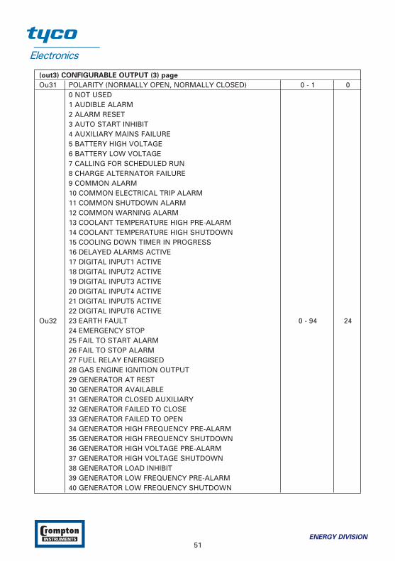
(out3) CONFIGURABLE OUTPUT (3) page
Ou31 POLARITY (NORMALLY OPEN, NORMALLY CLOSED) 0 - 1 00 NOT USED1 AUDIBLE ALARM2 ALARM RESET3 AUTO START INHIBIT4 AUXILIARY MAINS FAILURE5 BATTERY HIGH VOLTAGE6 BATTERY LOW VOLTAGE7 CALLING FOR SCHEDULED RUN8 CHARGE ALTERNATOR FAILURE9 COMMON ALARM10 COMMON ELECTRICAL TRIP ALARM11 COMMON SHUTDOWN ALARM12 COMMON WARNING ALARM13 COOLANT TEMPERATURE HIGH PRE-ALARM14 COOLANT TEMPERATURE HIGH SHUTDOWN15 COOLING DOWN TIMER IN PROGRESS16 DELAYED ALARMS ACTIVE17 DIGITAL INPUT1 ACTIVE18 DIGITAL INPUT2 ACTIVE19 DIGITAL INPUT3 ACTIVE20 DIGITAL INPUT4 ACTIVE21 DIGITAL INPUT5 ACTIVE22 DIGITAL INPUT6 ACTIVE
Ou32 23 EARTH FAULT 0 - 94 2424 EMERGENCY STOP25 FAIL TO START ALARM26 FAIL TO STOP ALARM27 FUEL RELAY ENERGISED28 GAS ENGINE IGNITION OUTPUT29 GENERATOR AT REST30 GENERATOR AVAILABLE31 GENERATOR CLOSED AUXILIARY32 GENERATOR FAILED TO CLOSE33 GENERATOR FAILED TO OPEN34 GENERATOR HIGH FREQUENCY PRE-ALARM35 GENERATOR HIGH FREQUENCY SHUTDOWN36 GENERATOR HIGH VOLTAGE PRE-ALARM37 GENERATOR HIGH VOLTAGE SHUTDOWN38 GENERATOR LOAD INHIBIT39 GENERATOR LOW FREQUENCY PRE-ALARM40 GENERATOR LOW FREQUENCY SHUTDOWN
ENERGY DIVISION
51
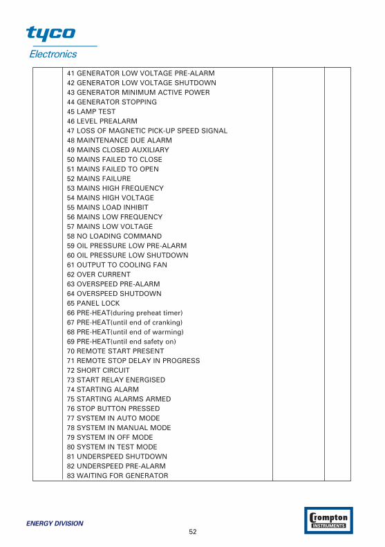
41 GENERATOR LOW VOLTAGE PRE-ALARM42 GENERATOR LOW VOLTAGE SHUTDOWN43 GENERATOR MINIMUM ACTIVE POWER44 GENERATOR STOPPING45 LAMP TEST46 LEVEL PREALARM 47 LOSS OF MAGNETIC PICK-UP SPEED SIGNAL48 MAINTENANCE DUE ALARM49 MAINS CLOSED AUXILIARY50 MAINS FAILED TO CLOSE51 MAINS FAILED TO OPEN52 MAINS FAILURE53 MAINS HIGH FREQUENCY54 MAINS HIGH VOLTAGE55 MAINS LOAD INHIBIT56 MAINS LOW FREQUENCY57 MAINS LOW VOLTAGE58 NO LOADING COMMAND59 OIL PRESSURE LOW PRE-ALARM60 OIL PRESSURE LOW SHUTDOWN61 OUTPUT TO COOLING FAN62 OVER CURRENT63 OVERSPEED PRE-ALARM64 OVERSPEED SHUTDOWN65 PANEL LOCK66 PRE-HEAT(during preheat timer)67 PRE-HEAT(until end of cranking)68 PRE-HEAT(until end of warming)69 PRE-HEAT(until end safety on)70 REMOTE START PRESENT71 REMOTE STOP DELAY IN PROGRESS72 SHORT CIRCUIT73 START RELAY ENERGISED74 STARTING ALARM75 STARTING ALARMS ARMED76 STOP BUTTON PRESSED77 SYSTEM IN AUTO MODE78 SYSTEM IN MANUAL MODE79 SYSTEM IN OFF MODE80 SYSTEM IN TEST MODE81 UNDERSPEED SHUTDOWN82 UNDERSPEED PRE-ALARM83 WAITING FOR GENERATOR
52ENERGY DIVISION

CONFIGURABLE OUTPUT SELECTIONS
0 NOT USED
Output is not used
1 AUDIBLE ALARM
The output indicates that the internal sounder is operating. It may be used for an externalsounder.
2 ALARM RESET
The output indicates that an alarm reset being performed. Once the alarm reset has beencompleted, the output becomes inactive again. The output could be used to give an externalreset signal to external systems.
3 AUTO START INHIBIT
This output indicates that a digital input that has been configured as ‘auto start inhibit’ is active.
4 AUXILIARY MAINS FAILURE
This output indicates that a digital input that has been configured as ‘auxiliary mains failure’ isactive.
5 BATTERY HIGH VOLTAGE
This output indicates that a battery high voltage alarm has occurred.
6 BATTERY LOW VOLTAGE
This output indicates that a battery low voltage alarm has occurred.
7 CALLING FOR SCHEDULED RUN
This output indicates that a scheduled run has been called for. If the module is in the ‘auto’ andmains ok, the module will change mode to ‘test’ and the generator will run if no shutdownalarms are present.
8 CHARGE ALTERNATOR FAILURE
This output indicates that a charging alternator failure has occurred
9 COMMON ALARM
This output indicates that a warning, electrical trip or shutdown alarm has been activated.
10 COMMON ELECTRICAL TRIP ALARM
This output indicates that an electrical trip alarm has been activated. This output can only bereset by removal of the fault and by then pressing the RESET button.
11 COMMON SHUTDOWN ALARM
This output indicates that a shutdown alarm has been activated. This output can only be resetby removal of the fault and by then pressing the RESET button or by using an external ‘alarmreset’ input.
ENERGY DIVISION
53
12 COMMON WARNING ALARM
This output indicates that a warning alarm has been activated. This output is normally self-resetting on removal of the fault.
13 COOLANT TEMPERATURE HIGH PRE-ALARM
This output indicates that a high engine coolant temperature warning (pre-alarm) has occurred.
14 COOLANT TEMPERATURE HIGH SHUTDOWN
This output indicates that a high engine coolant temperature shutdown has occurred.
15 COOLING DOWN TIMER IN PROGRESS
This output source will be active when the cooling off-load timer is running.
16 DELAYED ALARMS ACTIVE
The output indicates that the delayed alarms are now enabled. Can be used to control externallogic circuitry.
17 DIGITAL INPUT1 ACTIVE
This output indicates that digital input 1 is active.
18 DIGITAL INPUT2 ACTIVE
This output indicates that digital input 2 is active.
19 DIGITAL INPUT3 ACTIVE
This output indicates that digital input 3 is active.
20 DIGITAL INPUT4 ACTIVE
This output indicates that digital input 4 is active.
21 DIGITAL INPUT5 ACTIVE
This output indicates that digital input 5 is active.
22 DIGITAL INPUT6 ACTIVE
This output indicates that digital input 6 is active.
23 EARTH FAULT
This output indicates that the module has detected that an earth fault exists on the generatoroutput.
24 EMERGENCY STOP
This output indicates that an emergency stop alarm has occurred.
25 FAIL TO START ALARM
This output indicates that the engine has not started after the specified number of attempts.
54ENERGY DIVISION

26 FAIL TO STOP ALARM
This output indicates that the generator has failed to stop within the selected time
27 FUEL RELAY ENERGISED
The output mimics the operation of the fuel relay. Can be used to control external logic circuitry.
28 GAS ENGINE IGNITION OUTPUT
29 GENERATOR AT REST
The output indicates that the generator is not running.
30 GENERATOR AVAILABLE
This output indicates when the generator is ready to accept load, i.e. after safety on and warmup timers have timed out.
31 GENERATOR CLOSED AUXILIARY
This output indicates that a digital input that has been configured as ‘generator closed auxiliary’is active.
32 GENERATOR FAILED TO CLOSE
This output source has intended to be used to indicate a failure of the generator contactor orbreaker. It can only be used if the module is configured to use ‘generator closed auxiliary’feedback.
33 GENERATOR FAILED TO OPEN
This output source has intended to be used to indicate a failure of the generator contactor orbreaker. It can only be used if the module is configured to use ‘generator closed auxiliary’feedback.
34 GENERATOR HIGH FREQUENCY PRE-ALARM
This output indicates that a generator high frequency warning (pre-alarm) has occurred.
35 GENERATOR HIGH FREQUENCY SHUTDOWN
This output indicates that a generator high frequency shutdown has occurred.
36 GENERATOR HIGH VOLTAGE PRE-ALARM
This output indicates that a generator high voltage warning (pre-alarm) has occurred.
37 GENERATOR HIGH VOLTAGE SHUTDOWN
This output indicates that a generator high voltage shutdown has occurred.
38 GENERATOR LOAD INHIBIT
This output indicates that a digital input has been configured as ‘generator load inhibit’ is active.
ENERGY DIVISION
55
39 GENERATOR LOW FREQUENCY PRE-ALARM
This output indicates that a generator low frequency warning (pre-alarm) has occurred.
40 GENERATOR LOW FREQUENCY SHUTDOWN
This output indicates that a generator low frequency shutdown has occurred.
41 GENERATOR LOW VOLTAGE PRE-ALARM
This output indicates that a generator low voltage warning (pre-alarm) has occurred.
42 GENERATOR LOW VOLTAGE SHUTDOWN
This output indicates that a generator low voltage shutdown has occurred.
43 GENERATOR MINIMUM ACTIVE POWER
This output indicates that a generator minimum active power alarm has occurred.
44 GENERATOR STOPPING
This output source indicates that the engine has been instructed to stop but has not come torest.
45 LAMP TEST
This output indicates that the module is performing a lamp test. Once the lamp test iscompleted, the output will become inactive again. The output can be used to feed a lamp test onexternal modules or panel lamps.
46 LEVEL PREALARM
This output indicates that a level warning (pre-alarm) has occurred.
47 LOSS OF MAGNETIC PICK-UP SPEED SIGNAL
This output indicates that the magnetic pick up signal is not sufficient to be used by the modulefor speed monitoring. The alarm can only operate if the speed signal fails to appear duringcranking. It is disabled if ‘multiple attempts to engage’ is selected. If the MPU fails during enginerunning this would result in an underspeed alarm.
48 MAINTENANCE DUE ALARM
This output indicates that the generator is now due for maintenance either because it has usedall the available running hours or the periodic maintenance time has expired. To clear the outputa maintenance reset must be performed.
49 MAINS CLOSED AUXILIARY
This output indicates that a digital input that has been configured as ‘mains closed auxiliary’ isactive.
50 MAINS FAILED TO CLOSE
This output source has intended to be used to indicate a failure of the mains contactor orbreaker. It can only be used if the module is configured to use ‘mains closed auxiliary’ feedback.
56ENERGY DIVISION
51 MAINS FAILED TO OPEN
This output source has intended to be used to indicate a failure of the mains contactor orbreaker. It can only be used if the module is configured to use ‘mains closed auxiliary’ feedback.
52 MAINS FAILURE
This output indicates that the module has sensed that a failure of the incoming AC mainssupply. This output will become active whenever the mains voltage or frequency goes out oflimits, or if the auxiliary mains failure input active (if used) and the mains transient timer hasexpired.
53 MAINS HIGH FREQUENCY
This output indicates that the module has sensed that the incoming AC mains supply frequencyhas exceeded the frequency limit setting.
54 MAINS HIGH VOLTAGE
This output indicates that the module has sensed that the incoming AC mains supply voltagehas exceeded the voltage limit setting.
55 MAINS LOAD INHIBIT
This output indicates that a digital input has been configured as ‘mains load inhibit’ is active.
56 MAINS LOW FREQUENCY
This output indicates that the module has sensed that the incoming AC mains supply frequencyhas fallen below the frequency setting.
57 MAINS LOW VOLTAGE
This output indicates that the module has sensed that the incoming AC mains supply voltagehas fallen below the voltage limit setting.
58 NO LOADING COMMAND
This output indicates that the module is not calling for the generator contactor or breaker to beclosed. Should the module close the generator contactor this output will become inactive.
59 OIL PRESSURE LOW PRE-ALARM
This output indicates that a low oil pressure warning (pre-alarm) has occurred.
60 OIL PRESSURE LOW SHUTDOWN
This output indicates that a low oil pressure shutdown has occurred.
61 OUTPUT TO COOLING FAN
This output indicates that an electric cooling fan to the radiator is active for 3 minutes afterengine shut down.
ENERGY DIVISION
57
62 OVER CURRENT ALARM
This output indicates that the over current trip level has been reached.
63 OVERSPEED PRE-ALARM
This output indicates that the over speed warning (pre-alarm) has occurred.
64 OVERSPEED SHUTDOWN
This output indicates that the over speed shutdown has occurred.
65 PANEL LOCK
This output indicates that the module ‘panel lock’ is active. If the panel lock input is active, themodul will not respond to operation of the Mode select or start buttons. This allows the moduleto be placed into a spesific mode (such as auto) and then secured.
66 PRE-HEAT(during preheat timer)
The output controls the pre-heater. Pre-heat output is available for the duration of pre-heattimer, which terminates prior to cranking.
67 PRE-HEAT(until end of cranking)
The output controls the pre-heater. As ‘ Pre-heat (during pre-heat timer)’ mode but pre-heat isalso available during cranking.
68 PRE-HEAT(until end of warming)
The output controls the pre-heater. As ‘ Pre-heat (until safety on)’ but pre-heat continues to beavailable until the warm-up timer has elapsed.
69 PRE-HEAT(until end safety on)
The output controls the pre-heater. As ‘ Pre-heat (until end of cranking)’ but pre-heat is alsoavailable while waiting for the delayed alarms to become active.
70 REMOTE START PRESENT
This output indicates that a digital input that has been configured as ‘remote start’ is active. Thisoutput could be used to pass the remote start signal on to elsewhere in the control system.
71 REMOTE STOP DELAY IN PROGRESS
This output source will be active to indicate that the return timer is running.
72 SHORT CIRCUIT
This output indicates that the module has detected a short circuit on the generator output.
73 START RELAY ENERGISED
The output mimics the operation of the start relay. Can be used to control external logiccircuitry.
58ENERGY DIVISION
74 STARTING ALARM
This output is used to supply an external sounder with a signal that the engine is about to start.The output will be active during the start delay and pre-heat timer (if used).
75 STARTING ALARMS ARMED
The output indicates that the starting alarms are now enabled. It can be used to control externallogic circuitry. Starting alarms are armed as soon as module commences starting of the engineand remain armed until the engine at rest.
76 STOP BUTTON PRESSED
This output indicates that the stop pushbutton being operated. Once the button is released theoutput will become inactive.
77 SYSTEM IN AUTO MODE
The output indicates that the module is in the Auto mode.
78 SYSTEM IN MANUAL MODE
The output indicates that the module is in the Manual mode.
79 SYSTEM IN OFF MODE
The output indicates that the module is in the Stop mode.
80 SYSTEM IN TEST MODE
The output indicates that the module is in the Test mode.
81 UNDERSPEED SHUTDOWN
This output indicates that an underspeed shutdown has occurred.
82 UNDERSPEED PRE-ALARM
This output indicates that an underspeed warning (pre-alarm) has occurred.
83 WAITING FOR GENERATOR
This output indicates that the engine has been instructed to start but has not yet becomeavailable. Once the generator becomes available this output will be in-active. (Available =generator frequency and voltage levels are above the ‘loading’ levels set in the configuration.)
(tı1) START TIMERS page
tı11 MAINS TRANSIENT DELAY sec 0 - 30 0tı12 REMOTE START DELAY sec 0 - 3600 4tı13 REMOTE STOP DELAY sec 0 - 250 4tı14 PRE-HEAT Sec 0 – 250 3tı15 PRE-HEAT BYPASS Min 0 – 250 0tı16 SAFETY ON DELAY sec 0 - 99 8tı17 HORN DURATION sec (dis)0 - 999 60
ENERGY DIVISION
59

MAINS TRANSIENT DELAY
This timer dictates how long a mains anomaly must be present before the module will respondto it. This can be used to prevent nuisance tripping when switching loads etc.
REMOTE START DELAY
This timer dictates how long the module will wait after it has received a remote start signalbefore it will attempt to start. This prevents un-necessary starting on a fluctuating mains supplyetc.
REMOTE STOP DELAY
This timer dictates how long the module will wait after it has received a remote stop signalbefore it will attempt to stop. This prevents un-necessary stopping on a fluctuating mains supplyetc.
PRE-HEAT
This timer dictates the duration that the pre-heat output will be active before an attempt is madeto start the engine. Once this timer is expired cranking will commence.
PRE-HEAT BYPASS
This feature allows the module to start a hot engine without performing an un-necessary pre-heat delay. The bypass timer is triggered by the generator starting and actually being loaded. Ifthe generator started but does not achieve loading then the timer will not be triggered. Thebypass timer is initiated once the engine has come to rest. If any attempts to start are requestedwithin the duration of the bypass timer the start sequence will bypass the pre-heat timer.
SAFETY ON DELAY
This timer dictates how long the module will ignore the Low Oil Pressure, High EngineTemperature, Underspeed, Undervolts and any other inputs configured as active from safety on.It allows the values such as oil pressure to rise to their operating values on starting withouttriggering an alarm. Once the timer has expired all alarm conditions are monitored again. Ifconfigured to use ‘fast loading’, should all the monitored conditions, such as oil pressure, cometo expected state prior to the end of the safety on timer, the timer will be terminatedprematurely ensuring maximum protection as soon as possible.
HORN DURATION
This timer dictates how long the horn will work after the last error detected. Once after this timerended module will do horn reset.
(tı2) LOAD/STOPPING TIMERS page
tı21 WARMUP TIMER sec 0 - 250 3tı22 RETURN DELAY Sec 0 – 3600 5tı23 COOLING TIMER Min 0 – 99 1tı24 GENERATOR FREQUENCY ERROR CONTROL TIME Sec 0.0 – 10.0 1.0tı25 GENERATOR VOLTAGE ERROR CONTROL TIME Sec 0.0 – 10.0 1.0tı26 FAIL TO STOP TIME sec 0 – 99 30
60ENERGY DIVISION

WARMUP TIMER
This timer is initiated once the engine is up and running. It delays loading the generator until ithas stabilised. Once this timer is expired the ‘Close generator’ signal will be given and thegenerator is available to be loaded.
RETURN DELAY
This timer dictates how long the module will wait before it will un-load the generator (back tothe mains supply if AMF) and initialise it’s run-on and shutdown cycle. This is ensure that themains supply has stabilised before transferring the load back to mains.
COOLING TIMER
This is the time the generator is to run off-load once the load transfer signal has ceased. Thidgives the engine time to cool down before shutdown.
GENERATOR FREQUENCY ERROR CONTROL TIME
If firstly generator frequency is out of under and over set points this timer initiated. If generatorfrequency is out of under and over set points when this timer expires a ‘generator frequencyerror’ alarm signal is generated.
GENERATOR VOLTAGE ERROR CONTROL TIME
If firstly generator voltage is out of under and over set points this timer initiated. If generatorvoltage is out of under and over set points when this timer expires a ‘generator voltage error’alarm signal is generated.
FAIL TO STOP TIME
Once the module has given a shutdown signal to the engine it expects the engine to come torest. It monitors the Oil pressure and speed sensing sources and if they still indicate enginemovement when this timer expires a ‘Fail To Stop’ alarm signal is generated.
(brEA) BREAKERS page
brSL HARDWARE BREAKER SELECTION 0 – 2 0GbCC GEN CLOSE BREAKER CONTACT TYPE NO/NC 0 – 1 0GbCr GEN CLOSE BREAKER RELAY TYPE NOR/PULS 0 – 1 0GbCt GEN CLOSE TIMER Sec 1 – 250 5GbOC GEN OPEN BREAKER CONTACT TYPE NO/NC 0 – 1 0GbOr GEN OPEN BREAKER RELAY TYPE NOR/PULS 0 – 1 0GbOt GEN OPEN TIMER Sec 1 – 250 5MbCC MAIN CLOSE BREAKER CONTACT TYPE NO/NC 0 – 1 0MbCr MAIN CLOSE BREAKER RELAY TYPE NOR/PULS 0 – 1 0MbCt MAINS CLOSE TIMER Sec 1 – 250 5MbOC MAIN OPEN BREAKER CONTACT TYPE NO/NC 0 – 1 0MbOr MAIN OPEN BREAKER RELAY TYPE NOR/PULS 0 – 1 0MbOt MAINS OPEN TIMER Sec 1 – 250 5brCP BREAKER CLOSE PULSE TIME Sec 0.0 – 10.0 0.5brOP BREAKER OPEN PULSE TIME Sec 0.0 – 10.0 0.5trtm TRANSFER TIME Sec 0 - 250 2
ENERGY DIVISION
61

HARDWARE BREAKER SELECTION
0- Mains and Gen schalters have only close drives and if close drive off schalter will open.Parameters; GEN CLOSE BREAKER CONTACT TYPE, GEN CLOSE TIMER(if gen closed inputselected), GEN OPEN TIMER(if gen closed input selected), MAIN CLOSE BREAKER CONTACTTYPE, MAINS CLOSE TIMER(if mains closed input selected), MAINS OPEN TIMER(if mainsclosed input selected), TRANSFER TIME.
1- Mains and Gen schalters have only close drives, when want to schalter close, close breakeroutput on and after 1 sec. open breaker output on and after breaker close pulse time openbreaker output will off. When want to schalter open close breaker output and open breakeroutput will off.Parameters; GEN CLOSE BREAKER CONTACT TYPE, GEN CLOSE TIMER(if gen closed inputselected), GEN OPEN BREAKER CONTACT TYPE, GEN OPEN TIMER(if gen closed inputselected), MAIN CLOSE BREAKER CONTACT TYPE, MAINS CLOSE TIMER(if mains closed inputselected), MAIN OPEN BREAKER CONTACT TYPE, MAINS OPEN TIMER(if mains closed inputselected),BREAKER CLOSE PULSE TIME, TRANSFER TIME.
2- USER CONFIGURED: User can select all the schalter types.Parameters; GEN CLOSE BREAKER CONTACT TYPE, GEN CLOSE BREAKER RELAY TYPE, GENCLOSE TIMER(if gen closed input selected), GEN OPEN BREAKER CONTACT TYPE, GEN OPENBREAKER RELAY TYPE, GEN OPEN TIMER(if gen closed input selected), MAIN CLOSE BREAKERCONTACT TYPE, MAIN CLOSE BREAKER RELAY TYPE, MAINS CLOSE TIMER(if mains closedinput selected), MAIN OPEN BREAKER CONTACT TYPE, MAIN OPEN BREAKER RELAY TYPE,MAINS OPEN TIMER(if mains closed input selected), BREAKER CLOSE PULSE TIME(if Gen CloseBreaker Relay Type or Main Close Breaker Relay Type parameter is selected as 1), BREAKEROPEN PULSE TIME(if Gen Open Breaker Relay Type or Main Open Breaker Relay Typeparameter is selected as 1), TRANSFER TIME.
GEN. CLOSE TIMER
This is used to monitor the closure of the generator contactor or breaker. It will only operate ifan auxiliary input is configured as ‘Generator Closed Auxiliary’ and connected to the auxiliary onthe generator contactor or breaker. Once a generator closed signal is issued the ‘gen closetimer’ is initiated. Should the ‘Generator Closed Auxiliary’ input become active the timer the‘gen close timer’ is cancelled. If the timer expires and the ‘Generator Closed Auxiliary’ has notbecome active the module will issue a ‘generator failed to close’ alarm.
GEN. OPEN TIMER
This is used to monitor the opening of the generator contactor or breaker. It will only operate ifan auxiliary input is configured as ‘Generator Closed Auxiliary’ and connected to the auxiliary onthe generator contactor or breaker. Once a generator open signal is issued the ‘gen open timer’is initiated. Should the ‘Generator Closed Auxiliary’ input become in-active the timer the ‘genopen timer’ is cancelled. If the timer expires and the ‘Generator Closed Auxiliary’ has notbecome in-active the module will issue a ‘generator failed to open’ alarm.
MAINS CLOSE TIMER
This is used to monitor the closure of the mains contactor or breaker. It will only operate if anauxiliary input is configured as ‘Mains Closed Auxiliary’ and connected to the auxiliary on themains contactor or breaker. Once a mains closed signal is issued the ‘mains close timer’ is
62ENERGY DIVISION
initiated. Should the ‘Mains Closed Auxiliary’ input become active the timer the ‘mains closetimer’ is cancelled. If the timer expires and the ‘Mains Closed Auxiliary’ has not become activethe module will issue a ‘mains failed to close’ alarm.
MAINS OPEN TIMER
This is used to monitor the opening of the mains contactor or breaker. It will only operate if anauxiliary input is configured as ‘Mains Closed Auxiliary’ and connected to the auxiliary on themains contactor or breaker. Once a mains open signal is issued the ‘mains open timer’ isinitiated. Should the ‘Mains Closed Auxiliary’ input become in-active the timer the ‘mains opentimer’ is cancelled. If the timer expires and the ‘Mains closed auxiliary’ has not become in-activethe module will issue a ‘mains failed to open’ alarm.
BREAKER CLOSE PULSE TIME
This is used to determine the duration of the Mains and Generator close signals. This timer isonly used if Pulsed outputs are configured to be used.
BREAKER OPEN PULSE TIME
This is used to determine the duration of the Mains and Generator close signals. This timer isonly used if Pulsed outputs are configured to be used.
TRANSFER TIME
This is used to allow for fixed duration transfer breaks when switching from mains to generatorand back. It can be used to ensure that the supply is removed from the load for fixed period oftime to allow pumps/motors to come to rest etc.
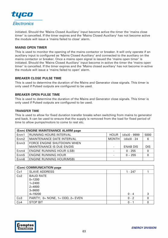
(Enm) ENGINE MAINTENANCE ALARM page
Enm1 RUNNING HOURS INTERVAL HOUR (dis)0 - 9999 5000Enm2 MAINTENANCE DATE INTERVAL MONTH (dis)0 - 24 6Enm3 FORCE ENGINE SHUTDOWN WHEN
MAINTENANCE IS DUE EN/DIS - ENAB DIS DISEnm4 ENGINE RUNNING HOUR (LSB) - 0 - 255 0Enm5 ENGINE RUNNING HOUR - 0 – 255 0Enm6 ENGINE RUNNING HOUR(MSB)
(Com) COMMUNICATION page
Co1 SLAVE ADDRESS 1 - 247 1Co2 BAUD RATE
0=12001=24002=48003=96004=19200 0 - 4 3
Co3 PARITY; 0= NONE, 1= ODD, 2= EVEN 0 - 2 0Co4 STOP BIT 0 - 1 0
ENERGY DIVISION
63
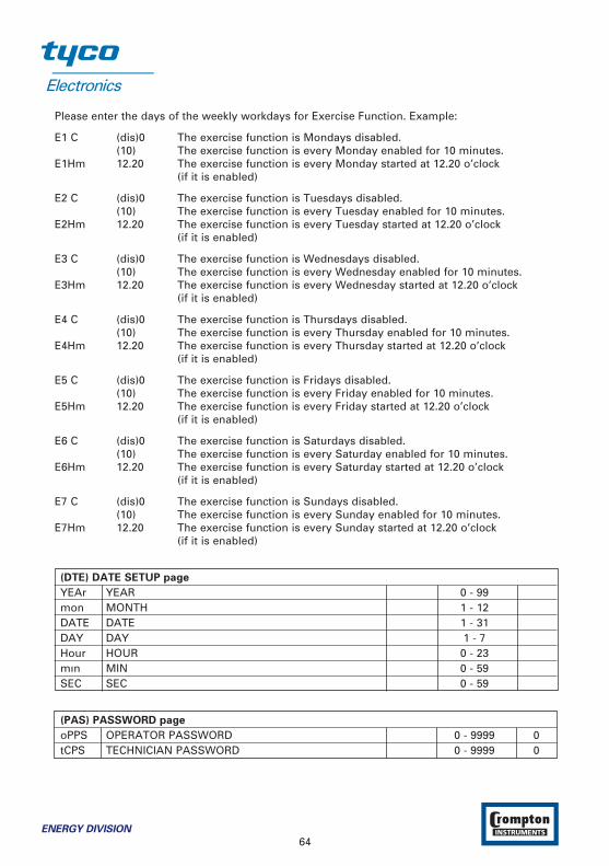
Please enter the days of the weekly workdays for Exercise Function. Example:
E1 C (dis)0 The exercise function is Mondays disabled.(10) The exercise function is every Monday enabled for 10 minutes.
E1Hm 12.20 The exercise function is every Monday started at 12.20 o’clock(if it is enabled)
E2 C (dis)0 The exercise function is Tuesdays disabled.(10) The exercise function is every Tuesday enabled for 10 minutes.
E2Hm 12.20 The exercise function is every Tuesday started at 12.20 o’clock(if it is enabled)
E3 C (dis)0 The exercise function is Wednesdays disabled.(10) The exercise function is every Wednesday enabled for 10 minutes.
E3Hm 12.20 The exercise function is every Wednesday started at 12.20 o’clock(if it is enabled)
E4 C (dis)0 The exercise function is Thursdays disabled.(10) The exercise function is every Thursday enabled for 10 minutes.
E4Hm 12.20 The exercise function is every Thursday started at 12.20 o’clock(if it is enabled)
E5 C (dis)0 The exercise function is Fridays disabled.(10) The exercise function is every Friday enabled for 10 minutes.
E5Hm 12.20 The exercise function is every Friday started at 12.20 o’clock(if it is enabled)
E6 C (dis)0 The exercise function is Saturdays disabled.(10) The exercise function is every Saturday enabled for 10 minutes.
E6Hm 12.20 The exercise function is every Saturday started at 12.20 o’clock(if it is enabled)
E7 C (dis)0 The exercise function is Sundays disabled.(10) The exercise function is every Sunday enabled for 10 minutes.
E7Hm 12.20 The exercise function is every Sunday started at 12.20 o’clock(if it is enabled)
(DTE) DATE SETUP page
YEAr YEAR 0 - 99mon MONTH 1 - 12DATE DATE 1 - 31DAY DAY 1 - 7Hour HOUR 0 - 23mın MIN 0 - 59SEC SEC 0 - 59
(PAS) PASSWORD page
oPPS OPERATOR PASSWORD 0 - 9999 0tCPS TECHNICIAN PASSWORD 0 - 9999 0
64ENERGY DIVISION
OPERATOR PASSWORD
Use this option to change the Operator password. This password allows access to operatorparameters section.
TECHNICIAN PASSWORD
Use this option to change the Technician password. It allows access to both operator andtechnician parameters section.
To prevent changing unit program parameters by unauthorised personnel do not
share or duplicate the operator and technician passwords. In case of this situation,
change passwords immediately.
ENERGY DIVISION
65
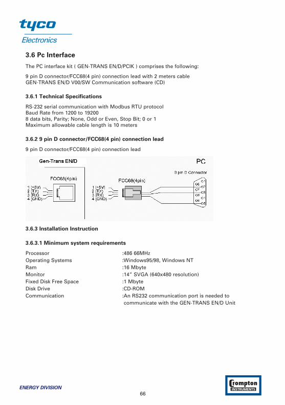
3.6 Pc Interface
The PC interface kit ( GEN-TRANS EN/D/PCIK ) comprises the following:
9 pin D connector/FCC68(4 pin) connection lead with 2 meters cableGEN-TRANS EN/D V00/SW Communication software (CD)
3.6.1 Technical Specifications
RS-232 serial communication with Modbus RTU protocolBaud Rate from 1200 to 192008 data bits, Parity; None, Odd or Even, Stop Bit; 0 or 1Maximum allowable cable length is 10 meters
3.6.2 9 pin D connector/FCC68(4 pin) connection lead
9 pin D connector/FCC68(4 pin) connection lead
3.6.3 Installation Instruction
3.6.3.1 Minimum system requirements
Processor :486 66MHzOperating Systems :Windows95/98, Windows NTRam :16 MbyteMonitor :14” SVGA (640x480 resolution)Fixed Disk Free Space :1 MbyteDisk Drive :CD-ROMCommunication :An RS232 communication port is needed to
communicate with the GEN-TRANS EN/D Unit
66ENERGY DIVISION
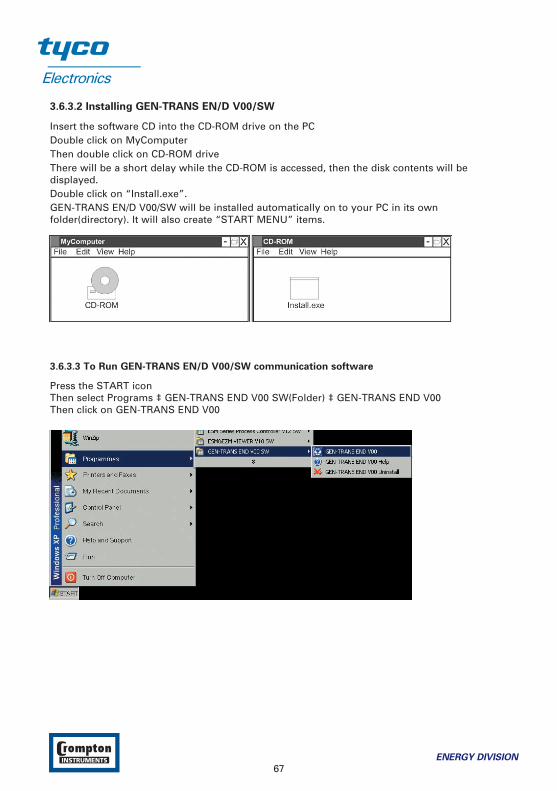
3.6.3.2 Installing GEN-TRANS EN/D V00/SW
Insert the software CD into the CD-ROM drive on the PCDouble click on MyComputerThen double click on CD-ROM driveThere will be a short delay while the CD-ROM is accessed, then the disk contents will bedisplayed.Double click on “Install.exe”.GEN-TRANS EN/D V00/SW will be installed automatically on to your PC in its ownfolder(directory). It will also create “START MENU” items.
3.6.3.3 To Run GEN-TRANS EN/D V00/SW communication software
Press the START iconThen select Programs ‡ GEN-TRANS END V00 SW(Folder) ‡ GEN-TRANS END V00Then click on GEN-TRANS END V00
ENERGY DIVISION
67
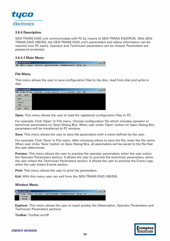
3.6.4 Description
GEN-TRANS EN/D unit communicates with PC by means of GEN-TRANS EN/D/PCIK. With GEN-TRANS EN/D V00/SW ,the GEN-TRANS EN/D unit’s parameters and status information can bereached over PC easily. Operator and Technician parameters can be viewed. Parameters arepassword protected.
3.6.4.1 Main Menu
File Menu
This menu allows the user to save configuration files to the disc, read from disc and write todisc.
Open: This menu allows the user to load the registered configuration files to PC.
For example: Click 'Open' in File menu. Choose configuration file which includes operator ortechnician parameters on Open Dialog Box. When user clicks 'Open' button on Open Dialog Boxparameters will be transferred to PC window.
Save: This menu allows the user to save the parameters with a name defined by the user.
For example: Click 'Save' in File menu. After choosing where to save the file, enter the file name.When user clicks 'Save' button on Save Dialog Box, all parameters will be saved to the file thatthe user determines.
Preview: This menu allows the user to preview the operator parameters, when the user entersthe Operator Parameters section. It allows the user to preview the technician parameters, whenthe user enters the Technician Parameters section. It allows the user to preview the Event Logs,when the user enters Events section.
Print: This menu allows the user to print the parameters.
Exit: With this menu user can exit from the GEN-TRANS EN/D V00/SW.
Window Menu
Explorer: This menu allows the user to reach quickly the Observation, Operator Parameters andTechnician Parameters sections.
Toolbar: Toolbar on/off
68ENERGY DIVISION

Program Menu
This menu is active when the Operator or Technician Parameters Section is open. With thismenu the user can load parameters from GEN-TRANS EN/D unit to PC or from PC to GEN-TRANS EN/D unit.
Download: With this menu the user can load parameters from PC to GEN-TRANS EN/D. Forloading parameters from PC to GEN-TRANS EN/D follow the steps below.
Download Current Page: While the operator parameters window is showing, If user clicks“Download Current Page” in Program menu, only parameters in the related page is loaded fromPC to device. While the technician parameters window is showing, If user clicks “DownloadCurrent Page” in Program menu, only parameters in the related page is loaded from PC todevice.
Download Current Parameter’s Page (Download All): While the operator parameters window isshowing, If user clicks “Download Current Parameter’s Page” in Program menu, all of theoperator parameters are loaded from PC to device. While the technician parameters window isshowing, If user clicks “Download Current Parameter’s Page” in Program menu, all of thetechnician parameters are loaded from PC to device.
Upload: User can load the parameters that are stored on GEN-TRANS EN/D unit to PC. Forloading parameters from GEN-TRANS EN/D unit to PC follow the steps below.
Upload Current Page: While the operator parameters window is showing, If user clicks “UploadCurrent Page” in Program menu, only parameters in the related page is loaded from device toPC. While the technician parameters window is showing, If user clicks “Upload Current Page” inProgram menu, only parameters in the related page is loaded from device to PC.
ENERGY DIVISION
69

Upload Current Parameter’s Page (Upload All): While the operator parameters window isshowing, If user clicks “Upload Current Parameter’s Page” in Program menu, all of the operatorparameters is loaded from device to PC. While the technician parameters window is showing, Ifuser clicks “Upload Current Parameter’s Page” in Program menu, all of the technicianparameters is loaded from device to PC.
Observation Menu
There are four sub-menus in this menu: Measurement Values, Failures, Events and Output &Modes.
Measurement Values
In this window the values listed below can be observed:
Mains volts (L1-N, L2-N, L3-N)Mains volts (L1-L2, L2-L3, L3-L1)Mains HzGenerator volts (L1-N, L2-N, L3-N)Generator volts (L1-L2, L2-L3, L3-L1)Generator HzLoad amps (IL1, IL2, IL3)
70ENERGY DIVISION

Earth current (IEA)Generator pfGenerator kVAGenerator kWGenerator kVArGenerator kVAhGenerator kWhGenerator kVArhNext maintenanceWorking timeReal timeCharge generator voltageBattery VoltageLevelPressureTemperatureEngine speed (Rpm)
Failures:
In this window the failures listed below can be observed:
Failed to startLow oil pressureHigh temperatureVoltage failureSpeed failure
ENERGY DIVISION
71

Charging failSpare 1Spare 2Spare 338 different error messages
Events:
In this window the last 32 Event logs can be observed:
72ENERGY DIVISION
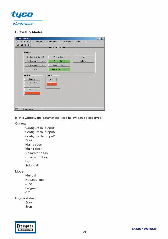
Outputs & Modes:
In this window the parameters listed below can be observed:
Outputs:Configurable output1Configurable output2Configurable output3StartMains openMains closeGenerator openGenerator closeHornSolenoid
Modes:ManualNo Load TestAutoProgramOff
Engine status:StartStop
ENERGY DIVISION
73

Operator Parameters Menu
Operator can reach the parameters in this menu. Parameters are password protected. When theoperator password is entered, it is compared with operator password that is registered on GEN-TRANS EN/D unit.
Entering the Operator Parameters Section
Click Mains Level in Operator Parameter menu. The Operator Password is required. Enter theOperator Password and click OK button. If the password is correct, first page of the operatorparameters (Mains Levels page) will be viewed.
74ENERGY DIVISION

Technician Parameters Menu
All parameters can be viewed in this menu. Parameters are password protected. When thetechnician password is entered, it is compared with technician password that is registered onGEN-TRANS EN/D unit.
Entering the Technician Parameters Section
Click Mains Level in Technician Parameter menu. The Technician Password is required. Enter theTechnician Password and click OK button. If the password is correct, first page of the technicianparameters (Mains Levels page) will be viewed.
ENERGY DIVISION
75
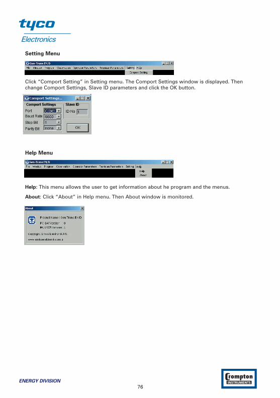
Setting Menu
Click “Comport Setting” in Setting menu. The Comport Settings window is displayed. Thenchange Comport Settings, Slave ID parameters and click the OK button.
Help Menu
Help: This menu allows the user to get information about he program and the menus.
About: Click “About” in Help menu. Then About window is monitored.
76ENERGY DIVISION

4 Commissioning
These commissioning checks may interfere with the power supply to the load. Therefore theyshould not be carried out with a mission-critical load connected to the system.
4.1 Manual operation
1. Check that the unit is correctly wired and that the wiring is of a standard and rating compatible with the system.
2. Check that the correct fuses are fitted.
3. Program the unit as detailed in Section 3 Definition Of Front Panel And Programming.
4. Take temporary steps to prevent the engine from starting . (for example, disable the fuel solenoid.)
5. After a visual inspection to ensure it is safe to proceed, connect the battery supply.
6. On the GEN-TRANS EN/D, press the Man (33) button. The associated LED (14) should light.
7. Press the Engine Start (21) button. At this moment the LED (8) turns on.
8. Check that the engine start sequence commences. The starter motor should run for the programmed time period (cranking time) for the pre-set number of times (number of start attempts).
9. Check that the Failed to Start LED flashes and the LED (8) turns off.
10. Check the unit will change to the OFF mode and the LED (11) turns on.
11. Restore the engine to operational state (reconnect the fuel solenoid).
12. Press the Man (33) button. The LED (14) will turn on.
13. Press the Engine Start (21) button. The LED (8) will turn on.
14. Check the start sequence, as follows:
the starter motor runs
the engine starts
the starter motor disengages once the engine is running.
If not, check that the engine is fully operational (fuel available etc.) and check the wiring and programming of the GEN-TRANS EN/D.
15. Check that the engine runs up to its operating speed. If not and an alarm is present, check that the alarm is valid and then check the input wiring.
16. Press the Engine Stop (22) button. At this moment the LED (9) will turn on. The engine should stop. Allow time for the engine to come to rest.
ENERGY DIVISION
77
4.2 Auto Operation
1. Check that the mains is connected to the unit and is present.
2. Check the mains voltage readings on the display.
3. At the GEN-TRANS EN/D, press the Auto (31) button. The LED (12) on the button should light.
4. Switch off the mains supply to the unit. Check that the generator starts and, after a delay, the load is transferred to the generator.
5. Restore the mains supply to the unit. Check that, after a delay, the load is transferred back tothe mains and the generator, after a further delay, shuts down.
4.3 Test Mode Operation
1. Check that the mains is connected to the unit.
2. Press the Test (32) button. At this moment the LED (13) will turn on.
3. Check that the generator starts and that the load is still connected to the mains.
4. Switch off the mains supply. Check that the contactors change over to connect the load to the generator. Check also that the Auto (12) LED is lit. The unit changes operating mode to AUTO Mode automatically.
5. Restore the mains supply. Check that the contactors reconnect the load to the mains supply.
6. Check that the generator shuts down with cool-down period.
78ENERGY DIVISION
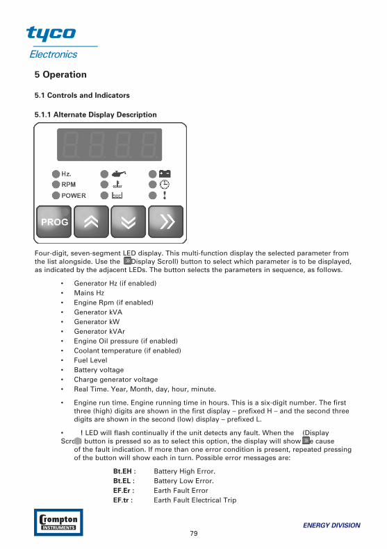
5 Operation
5.1 Controls and Indicators
5.1.1 Alternate Display Description
Four-digit, seven-segment LED display. This multi-function display the selected parameter fromthe list alongside. Use the (Display Scroll) button to select which parameter is to be displayed,as indicated by the adjacent LEDs. The button selects the parameters in sequence, as follows.
• Generator Hz (if enabled)• Mains Hz• Engine Rpm (if enabled)• Generator kVA• Generator kW• Generator kVAr• Engine Oil pressure (if enabled)• Coolant temperature (if enabled)• Fuel Level• Battery voltage• Charge generator voltage• Real Time. Year, Month, day, hour, minute.
• Engine run time. Engine running time in hours. This is a six-digit number. The first three (high) digits are shown in the first display – prefixed H – and the second three digits are shown in the second (low) display – prefixed L.
• ! LED will flash continually if the unit detects any fault. When the (Display Scroll) button is pressed so as to select this option, the display will show the cause
of the fault indication. If more than one error condition is present, repeated pressing of the button will show each in turn. Possible error messages are:
Bt.EH : Battery High Error.Bt.EL : Battery Low Error.EF.Er : Earth Fault ErrorEF.tr : Earth Fault Electrical Trip
ENERGY DIVISION
79
EF.ur : Earth Fault WarningEnG.F : Multiple engage failE.StP : Emergency Stop.GB.CA : Generator Breaker Not Closed alarmGB.OA : Generator Breaker Not Opened alarmGOF.P : Generator Over Frequency PrealarmGOV.P : Generator Over Voltage PrealarmGUF.P : Generator Under Frequency PrealarmGUV.P : Generator Under Voltage PrealarmLVL.E : Fuel Level Error.LVL.P : Fuel Level Prealarm.M.Er : Maintenance errorMB.CA : Mains Breaker Not Closed alarmMB.OA : Mains Breaker Not Opened alarmOC.Er : Over Current ErrorOC.tr : Over Current Electrical TripOC.ur : Over Current WarningOSP.E : Over speed errorOSP.P : Over speed pre-alarmPrS.P : Oil Pressure Prealarm.RP.Er : Reverse Power ErrorRP.ur : Reverse Power WarningRP.tr : Reverse Power Electrical TripSC.Er : Short Circuit ErrorSC.tr : Short Circuit Electrical TripSC.ur : Short Circuit WarningSP4.E : Spare 4 Error.SP5.E : Spare 5 Error.SP6.E : Spare 6 Error.SPE.L : Speed loss errorStP.E : Generator Stop Error.TP.PA : Generator Temperature Prealarm.USP.E : Under speed errorUSP.P : Under speed pre-alarm
The ! LED will be skipped if there are no faults.
• Event messages. When The Eunt message is displayed, Events (from 1 to 32) can be displayed sequencely with the and buttons. Possible Event messages are:
EV.01: generator low voltage pre-alarmEV.02: generator low voltage shutdownEV.03: generator high voltage pre-alarmEV.04: generator high voltage shutdownEV.05: generator low frequency pre-alarmEV.06: generator low frequency shutdownEV.07: generator high frequency pre-alarm
80ENERGY DIVISION

EV.08: generator high frequency shutdownEV.09: generator low speed pre-alarmEV.10: generator low speed shutdownEV.11: generator high speed pre-alarmEV.12: generator high speed shutdownEV.13: generator maintenance errorEV.14: generator maintenance warningEV.15: charge alternator failEV.16: generator fail to startEV.17: generator fail to stopEV.18: battery low voltage alarmEV.19: battery high voltage alarmEV.20: high temperature pre-alarmEV.21: high temperature shutdownEV.22: oil pressure pre-alarmEV.23: oil pressure shutdownEV.24: fuel level pre-alarmEV.25: fuel level alarmEV.26: emergency stop errorEV.27: spare 1 errorEV.28: spare 2 errorEV.29: spare 3 errorEV.30: spare 4 errorEV.31: spare 5 errorEV.32: spare 6 errorEV.33: mains breaker close errorEV.34: mains breaker open errorEV.35: gen breaker close errorEV.36: gen breaker open errorEV.37: over current alarmEV.38: short circuit alarmEV.39: earth fault alarmEV.40: reverse power alarmEV.41: magnetic pickup loss of speed errorEV.46: changed mode to offEV.47: changed mode to manualEV.48: changed mode to testEV.49: changed mode to auto
ENERGY DIVISION
81
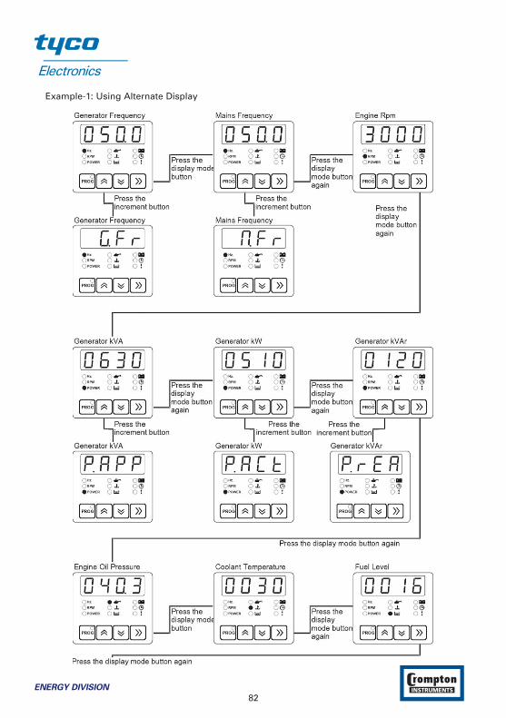
Example-1: Using Alternate Display
82ENERGY DIVISION
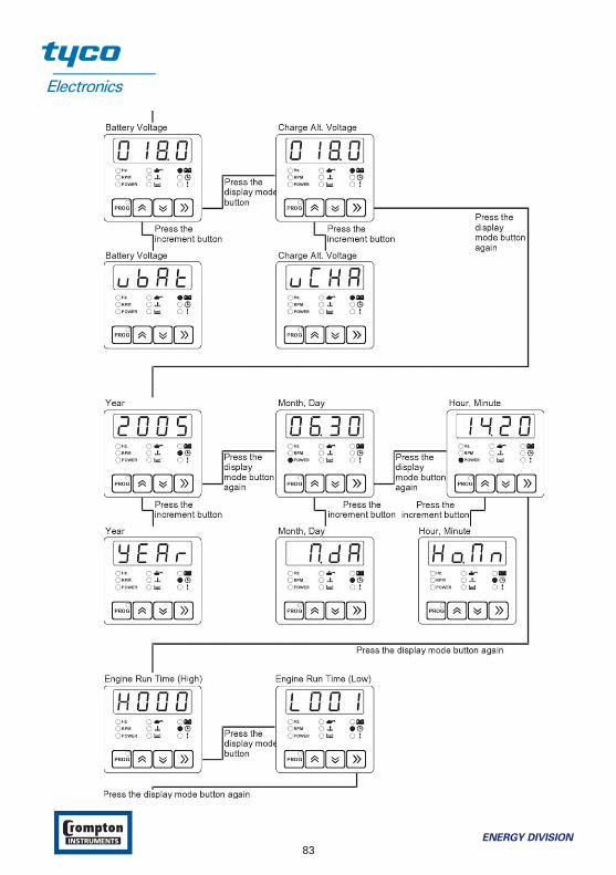
ENERGY DIVISION
83
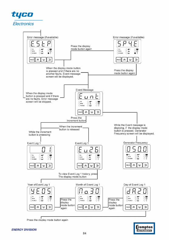
84ENERGY DIVISION

ENERGY DIVISION
85
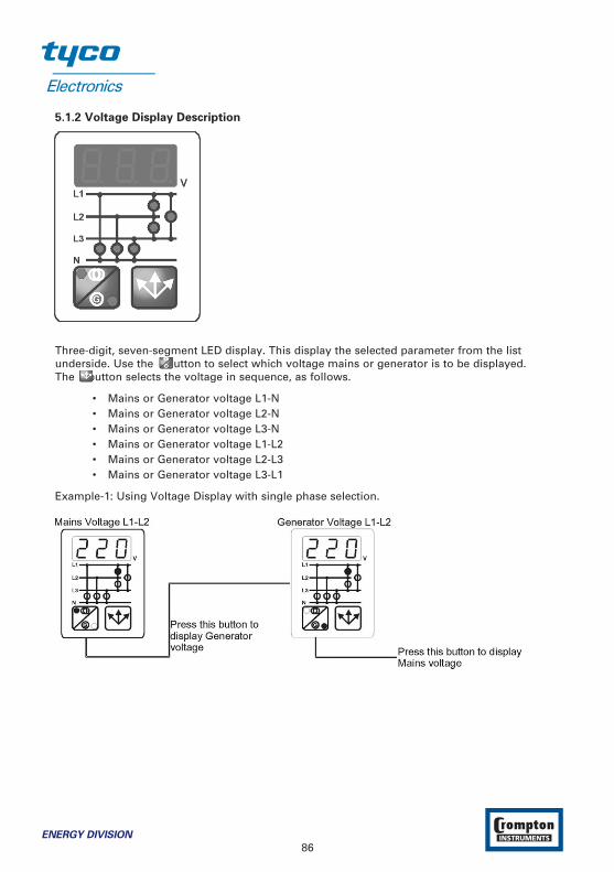
5.1.2 Voltage Display Description
Three-digit, seven-segment LED display. This display the selected parameter from the listunderside. Use the button to select which voltage mains or generator is to be displayed. The button selects the voltage in sequence, as follows.
• Mains or Generator voltage L1-N• Mains or Generator voltage L2-N• Mains or Generator voltage L3-N• Mains or Generator voltage L1-L2• Mains or Generator voltage L2-L3• Mains or Generator voltage L3-L1
Example-1: Using Voltage Display with single phase selection.
86ENERGY DIVISION
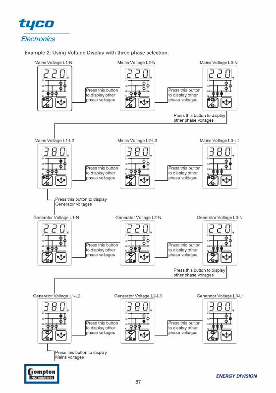
Example-2: Using Voltage Display with three phase selection.
ENERGY DIVISION
87

5.1.3 Current Display Description
Three-digit, seven-segment LED displays. Theese displays, including:
• Load Amps (IL1, IL2, IL3)• Load earth current (IE)• Generator kVAh• Generator kWh• Generator kVArh• Generator pf
Example-1: Displaying Load Amps (IL1, IL2, IL3).
Example-2: Displaying Earth Current (IEA).
88ENERGY DIVISION
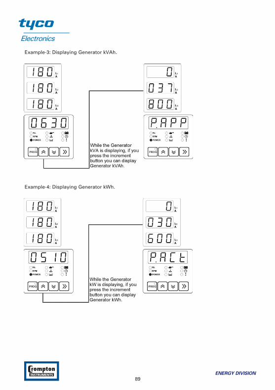
Example-3: Displaying Generator kVAh.
Example-4: Displaying Generator kWh.
ENERGY DIVISION
89
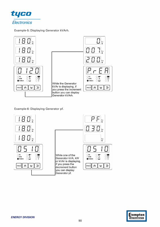
Example-5: Displaying Generator kVArh.
Example-6: Displaying Generator pf.
90ENERGY DIVISION

5.1.4 Failure Indicators Description
Explanations:
1 Failed to Start LED : This LED flashes if the engine has not started after the programmed number of attempts. The unit must be reset, by pressing the Reset button, before a fresh attempt can be made.
2- Low Oil Pressure Failure LED : This LED flashes if the Oil Pressure Switch/Sender on the engine indicates low oil pressure while the engine is running. If this fault occurs, the unit willstop the engine without any cool-down period.
3- High Temperature Failure LED : This LED flashes if the Thermostatic Switch/Sender on the engine indicates high temperature while the engine is running. If this fault occurs, the unit will stop the engine without any cool-down period.
4- Over Speed Failure LED : This LED flashes if the Alternator Frequency goes below the Generator Under Frequency parameter or above theGenerator Over Frequency parameter. For a fault to be indicated, the speed must be outside these limits for longer than the period defined by the Generator Frequency Error Control Time parameter. This failure immediately stops the generating set, without any cool-down period.
5- Voltage Failure LED : This LED flashes if the Alternator output voltage is outside of the limitsprogrammed into Generator Under Voltage parameter, and Generator Over Voltage parameter, For a time period longer than the Generator Voltage Error Control Time parameter. This failure immediately releases the generator contactor, and stops the generating set, without any cool-down period.
6- Charge Generator Failure LED : This LED flashes if the field current for the battery charge generator fails to fall to zero after the engine has started. A fault will not be indicated if the current falls within the period defined by the Safety On Delay parameter after the engine hasstarted. This failure will not stop the generating set.
ENERGY DIVISION
91
7- Configurable Input-1 LED (SPARE 1): This LED indicate the status of the input Pin 21, and thecontroller can be programmed to perform 22 different functions when this input is asserted.
8- Configurable Input-2 LED (SPARE 2): This LED indicate the status of the input Pin 20, and thecontroller can be programmed to perform 22 different functions when this input is asserted.
9- Configurable Input-3 LED (SPARE 3): This LED indicate the status of the input Pin 19, and thecontroller can be programmed to perform 22 different functions when this input is asserted.
5.2 Mode transition
The mode can be changed at any time. A change in mode will not effect the current state of thegenerator or load connection. For example; if the unit is in Auto mode with the generatorrunning and the load running on the generator, changing the mode to Manual will not effect theoperating state. Any changes between Auto, Manual and Test modes will not change theoperating state.
5.3 Manual Start
1. Press the Man (33) button. The LED (14) will turn on.
2. Press the Engine Start (21) button on the panel the LED (8) will turn on. The engine should start. The sequence is as follows:
• The starter motor runs• The engine starts
Once the engine is running,
• The LED (7) “Engine Running” is lit.• The “Generator Ready” LED (6) is lit after “safety on delay” time period like as
AUTO mode.• It is not possible supply to load on the generator unless “Generator Ready” LED (6)
is lit. (The contactor open / close button will not work)
3. Once LEDs have lit, press the Mains contactor open button (18) to disconnect the load from the mains supply. LED (4) should go off.
4. Press the Generator contactor close button (19) to connect the load to the generator supply. LED (5) should light.
5.4 Manual Stop
The LED (9) is lit and engine is stopped when the “Engine Stop” (22) button is pressed. Whenthe “Engine Stop” button is pressed while the load connected to the alternator output(generator output) first alternator contactor is released then engine is stopped.
5.5 Auto Operation
Press the Auto (31) button to select Auto mode. The LED (12) in the corner of the button willlight to indicate this mode has been selected.
92ENERGY DIVISION
In the event of a mains voltage failure, the unit will start up the generator and, once thegenerator is running and alternator voltage available, will transfer the load to the generator.When the mains is restored and stable, it will transfer the load back to the mains and, after acool-down period, shut down the generator.
5.6 Test Operation
Press the Test (32) button to select Test mode the LED (13) will turn on. This mode allows fortesting of the generator off load. All alarm circuits will operate so that any faults will bereported. If a mains failure occurs while the unit is in Test mode, the unit will revert to Automode and will switch the load to the generator.
5.6.1 Exercise Function
Please enter the days of the weekly workdays for Exercise Function. Example:
E1 C (dis)0 The exercise function is Mondays disabled.(10) The exercise function is every Monday enabled for 10 minutes.
E1Hm 12.20 The exercise function is every Monday started at 12.20 o’clock(if it is enabled)
When the Real-Time clock reaches the Generator Exercise Work Start Time (12.20 o’clock) if theunit is in “AUTO MODE” and Mains is available the unit changes running mode to the “TESTMODE” automatically and starts the engine. The time period of engine running is counted andcompared with value of Generator Exercise Working Time parameter (10 minutes). (If the enginedoes not run time is not counted). If the time is completed the unit changes run mode to“AUTO” automatically. When the unit is in the “TEST MODE” if the Mains is absent, the unit willchange mode to “AUTO MODE” automatically.
ENERGY DIVISION
93
6 Fault Finding
6.1 General
Indicators on the central section of the panel will flash if a fault is detected. For details seeSection 5.1.4 Failure Indicators Description. Fault conditions latch so that further operation isprevented. If a failure is indicated, proceed as follows:
1. Find and fix the fault.2. Press the Failure Reset (29) button to enable a restart.3. Select the required mode of operation – Manual, Auto or Test.
6.2 Error Messages
In addition to the indicators on the centre panel, the ! LED will flash in the event of a fault. Todiscover the fault being reported by the ! LED, press repeatedly (Display Scroll) button untilthis option has been selected. The display will indicate the fault condition, as follows. If there ismore than one fault message, repeated pressing of the (Display Scroll) button will show eachin turn. If there are no fault messages, the this option will be skipped. Error Messages are:
Bt.EH : This message indicates that a battery high voltage alarm has occured.Bt.EL : This message indicates that a battery low voltage alarm has occured.EF.Er : This message indicates that a earth fault shutdown has occured.EF.tr : This message indicates that a earth fault electrical trip has occured.EF.ur : This message indicates that a earth fault warning (pre-alarm) has occured.EnG.F : This message indicates that the multiple engage fail has occured.E.StP : This message indicates that an emergency stop alarm has occured.GB.CA : This message indicates that a generator breaker not closed alarm has occured.GB.OA : This message indicates that a generator breaker not opened alarm
has occured.GOF.P : This message indicates that a generator over frequency warning
(pre-alarm) has occured.GOV.P : This message indicates that a generator over voltage warning
(pre-alarm) has occured.GUF.P : This message indicates that a generator under frequency warning
(pre-alarm) has occured.GUV.P : This message indicates that a generator under voltage warning (pre-alarm)
has occured.LVL.E : This message indicates that the fuel level shutdown has occured.LVL.P : This message indicates that the fuel level warning (pre-alarm) has occured.M.Er : This message indicates that the generator is now due for maintenance.MB.CA : This message indicates that a mains breaker not closed alarm has occured.MB.OA : This message indicates that a mains breaker not opened alarm has occured.OC.Er : This message indicates that a over current shutdown has occured.OC.tr : This message indicates that a over current electrical trip has occured.OC.ur : This message indicates that a over current warning (pre-alarm) has occured.OSP.E : This message indicates that the over speed shutdown has occured.
94ENERGY DIVISION
OSP.P : This message indicates that the over speed warning (pre-alarm) has occured.PrS.P : This message indicates that a low oil pressure warning (pre-alarm)
has occured.RP.Er : This message indicates that a reverse power shutdown has occured.RP.ur : This message indicates that a reverse power warning (pre-alarm) has occured.RP.tr : This message indicates that a reverse power electrical trip has occured.SC.Er : This message indicates that a short circuit shutdown has occured.SC.tr : This message indicates that a short circuit electrical trip has occured.SC.ur : This message indicates that a short circuit warning (pre-alarm) has occured.SP4.E : This message indicates that a spare 4 alarm has occured.SP5.E : This message indicates that a spare 5 alarm has occured.SP6.E : This message indicates that a spare 6 alarm has occured.SPE.L : This message indicates that the magnetic pick-up sensor fail (speed loss error)
has occured.StP.E : This message indicates that the generator has failed to stop within the
selected time.TP.PA : This message indicates that a high engine coolant temperature warning
(pre-alarm) has occured.USP.E : This message indicates that the under speed shutdown has occured.USP.P : This message indicates that the under speed warning (pre-alarm) has occured.
ENERGY DIVISION
95

Table 6.1 Fault finding
Symptom Possible remedy
Unit is inoperative. Check the battery and wiring to the unit. Check the DC supply. ( measure voltage between pins 39 and 40 ) Check the DC fuse.
Low oil pressure fault Check engine oil level and pressure. operates after engine Check oil pressure switch/sender and wiring. has started. Check configured polarity (if applicable) is correct (i.e. Normally
Open or Normally Closed) or that sender is compatible with the device.
High engine temperature Check engine temperature.Fault operates after Check switch/sender and wiring. engine has started. Check configured polarity (if applicable) is correct (i.e. Normally
Open or Normally Closed) or that sender is compatible with the device.
Shutdown fault operates. Check relevant switch and wiring of fault indicated on the panel.Check configuration of input.
Warning fault operates. Check relevant switch and wiring of fault indicated on the panel.Check configuration of input.
Failed to Start fault. Check fuel solenoid and wiring, fuel and battery. Reset theEngine failed to start GEN-TRANS EN/D and restart the engine.after Pre-set number Check the signals that the GEN-TRANS EN/D is using toof Attempts. determine if the engine has started. Refer to engine manual.Starter motor Check wiring to starter solenoid.inoperative. Check battery supply.
Check battery supply is present on the Start output pin 33 of the GEN-TRANS EN/D.
Disconnect the equipment totally from electricity in the best and correct way
during mechanical and electrical maintenance. When this is not possible, the
equipment must be in the “OFF” position to prevent any accidents.
96ENERGY DIVISION
7 Specifications & Ratings
Specification: Description:
Equipment use Electrical control equipment for generating setsHousing & Mounting 144 mm x 204 mm x 37 mm. (including connectors) plastic
housing for panel mounting.Panel Cut-Out 138 mm x 186 mm.Protection IP54 at front panel, IP20 at rear side.Weight Approximately 0,72 Kg.Environmental rating Standard, indoor at an altitude of less then 2000 meters with
non-condensing humidity.Operating / Storage -25 C to +70 C / -40 C to +85 C TemperatureOperating / Storage 90 % max. (non-condensing)HumidityInstallation Over II Appliances, portable equipment.Voltage CategoryPollution Degree II, Normal office or workplace, non conductive pollutionMode of Operation ContinuousEMC EN 61000-6-4, EMC Generic Emission Standard for
industrial equipmentEN 61000-6-2, EMC Generic Immunity Standard for industrial equipment
Electrical Safety EN 61010-1, Safety Requirements for electrical equipment for measurement, control and laboratory use
DC Battery Supply Voltage 8 to 32 VDC max. operating current is 290 mA.Cranking Dropouts Battery voltage can be “0” VDC for max. 100 ms during
cranking (battery voltage should be at least nominal voltage before cranking).
Battery Voltage Measurement 8 to 32 VDC, accuracy: 1 % FS, resolution: 0,1 VMains Voltage Measurement Selectable three phase or single phase, 4 wire connection for
three phase, 2 wire connection for single phase gen-set. 35 to 300 VAC Ph-N, 15.6 to 99.9 Hz. Accuracy: 1 % FS, Resolution: 1 V
Mains Frequency 15.6 to 99.9 Hz (min. 35 VAC Ph-N) Accuracy: 0,25 % FS, Resolution: 0,1 Hz.
Generator Voltage Selectable three phase or single phase, 4 wire connection for Measurement three phase, 2 wire connection for single phase gen-set. 35 to
300 VAC Ph-N, 15.6 to 99.9 Hz. Accuracy: 1 % FS, Resolution: 1 VGenerator Speed From magnetic pick-up: 35 to 10000 Hz (4 to 35 volts peak
continuously.) Accuracy: 0,25 % FSGenerator Frequency From alternator voltage: 15.6 to 99.9 Hz (min. 35 VAC Ph-N)
Accuracy: 0,25 % FS, Resolution: 0,1 Hz.CT secondary 5A.Charge Generator Excitation 220mA, max 4W.
ENERGY DIVISION
97
Specification: Description:
Displays Three 3 digits,7 segments, LED displays showin:Load amps (IL1, IL2, IL3)Earth current (IEA)Generator kVAhGenerator kWhGenerator kVArhGenerator power factor (pf)
One 3 digits, 7 segments, LED display showin:Mains volts (L1-N, L2-N, L3-N)Mains volts (L1-L2, L2-L3, L3-L1)Generator volts (L1-N, L2-N, L3-N)Generator volts (L1-L2, L2-L3, L3-L1)
One 4 digits, 7 segments, LED display showin:Generator HzMains HzEngine RpmGenerator kVAGenerator kWGenerator kVArEngine oil pressureCoolant temperatureFuel levelBattery voltageCharge generator voltageReal timeEngine run timeError messagesEvent messagesProgram parameters
Failure Indicators Failed to startLow oil pressureHigh temperatureSpeed failureVoltage failureCharging failSpare 1Spare 2Spare 3
Status indicators OFF mode LEDTEST mode LEDAUTOMATIC mode LEDMANUAL mode LEDEngine start LEDEngine stop LEDEngine runningMain voltage available LEDGenerator ready LED
98ENERGY DIVISION
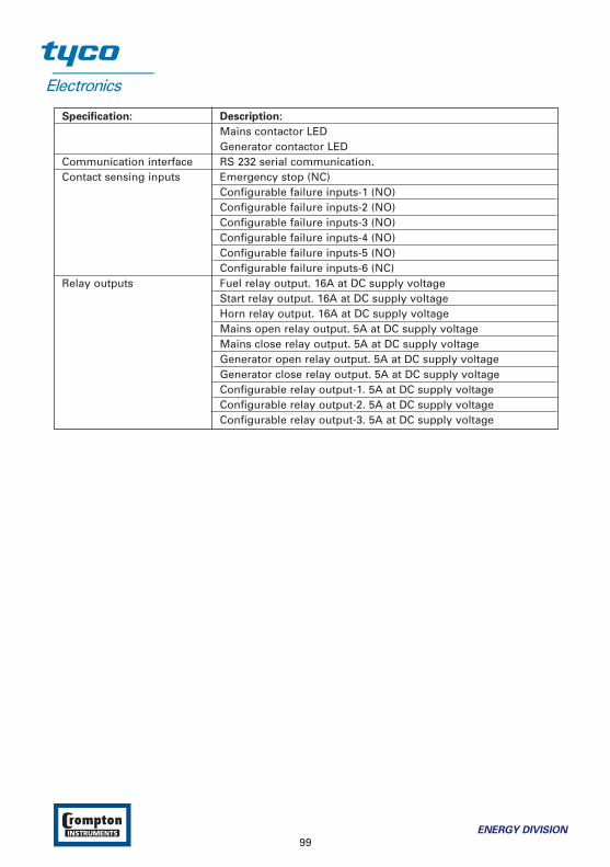
Specification: Description:
Mains contactor LEDGenerator contactor LED
Communication interface RS 232 serial communication.Contact sensing inputs Emergency stop (NC)
Configurable failure inputs-1 (NO)Configurable failure inputs-2 (NO)Configurable failure inputs-3 (NO)Configurable failure inputs-4 (NO)Configurable failure inputs-5 (NO)Configurable failure inputs-6 (NC)
Relay outputs Fuel relay output. 16A at DC supply voltageStart relay output. 16A at DC supply voltageHorn relay output. 16A at DC supply voltageMains open relay output. 5A at DC supply voltageMains close relay output. 5A at DC supply voltageGenerator open relay output. 5A at DC supply voltageGenerator close relay output. 5A at DC supply voltageConfigurable relay output-1. 5A at DC supply voltageConfigurable relay output-2. 5A at DC supply voltageConfigurable relay output-3. 5A at DC supply voltage
ENERGY DIVISION
99
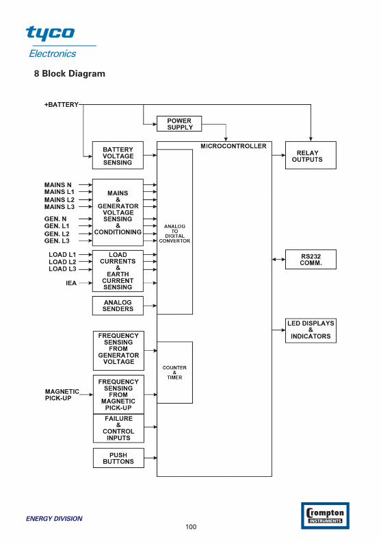
8 Block Diagram
100ENERGY DIVISION

User Defined Parameter:
List-1:
Definition of Parameter User Defined Value
Operator parameters
(mAL) MAINS LEVELS page
mA1 MAINS UNDER VOLTAGEmA2 MAINS UNDER VOLTAGE RETURNmA3 MAINS OVER VOLTAGEmA4 MAINS OVER VOLTAGE RETURNmA5 MAINS UNDER FREQUENCYmA6 MAINS UNDER FREQUENCY RETURNmA7 MAINS OVER FREQUENCYmA8 MAINS OVER FREQUENCY RETURN
(GnU) GENERATOR VOLTAGE LEVELS page
GnU1 GENERATOR UNDER VOLTAGEGnU2 GENERATOR UNDER VOLTAGE PRE-ALARMGnU3 GENERATOR LOADING VOLTAGEGnU4 GENERATOR OVER VOLTAGE PRE-ALARMGnU5 GENERATOR OVER VOLTAGE PRE-ALARM RETURNGnU6 GENERATOR OVER VOLTAGE SHUTDOWN
(GnF) GENERATOR FREQUENCY LEVELS page
GnF1 GENERATOR UNDER FREQUENCYGnF2 GENERATOR UNDER FREQUENCY PRE-ALARMGnF3 GENERATOR LOADING FREQUENCYGnF4 GENERATOR OVER FREQUENCY PRE-ALARMGnF5 GENERATOR OVER FRQ PRE-ALARM RETURNGnF6 GENERATOR OVER FREQUENCY SHUTDOWN
(Gno) GENERATOR CURRENT/POWER LEVELS page
Gno1 GENERATOR OVER CURRENTGno2 GENERATOR SHORT CIRCUITGno3 GENERATOR EARTH FAULTGno4 GENERATOR MINIMUM ACTIVE POWER
ENERGY DIVISION
101
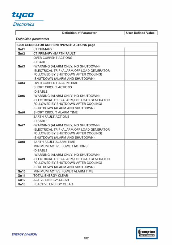
Definition of Parameter User Defined Value
Technician parameters
(Gnt) GENERATOR CURRENT/POWER ACTIONS page
Gnt1 CT PRIMARYGnt2 CT PRIMARY (EARTH FAULT)
OVER CURRENT ACTIONS-DISABLE
Gnt3 -WARNING (ALARM ONLY, NO SHUTDOWN)-ELECTRICAL TRIP (ALARM/OFF LOAD GENERATORFOLLOWED BY SHUTDOWN AFTER COOLING)-SHUTDOWN (ALARM AND SHUTDOWN)
Gnt4 OVER CURRENT ALARM TIMESHORT CIRCUIT ACTIONS-DISABLE
Gnt5 -WARNING (ALARM ONLY, NO SHUTDOWN)-ELECTRICAL TRIP (ALARM/OFF LOAD GENERATORFOLLOWED BY SHUTDOWN AFTER COOLING)-SHUTDOWN (ALARM AND SHUTDOWN)
Gnt6 SHORT CIRCUIT ALARM TIMEEARTH FAULT ACTIONS-DISABLE
Gnt7 -WARNING (ALARM ONLY, NO SHUTDOWN)-ELECTRICAL TRIP (ALARM/OFF LOAD GENERATORFOLLOWED BY SHUTDOWN AFTER COOLING)-SHUTDOWN (ALARM AND SHUTDOWN)
Gnt8 EARTH FAULT ALARM TIMEMINIMUM ACTIVE POWER ACTIONS-DISABLE-WARNING (ALARM ONLY, NO SHUTDOWN)
Gnt9 -ELECTRICAL TRIP (ALARM/OFF LOAD GENERATORFOLLOWED BY SHUTDOWN AFTER COOLING)-SHUTDOWN (ALARM AND SHUTDOWN)
Gn10 MINIMUM ACTIVE POWER ALARM TIMEGn11 TOTAL ENERGY CLEARGn12 ACTIVE ENERGY CLEARGn13 REACTIVE ENERGY CLEAR
102ENERGY DIVISION
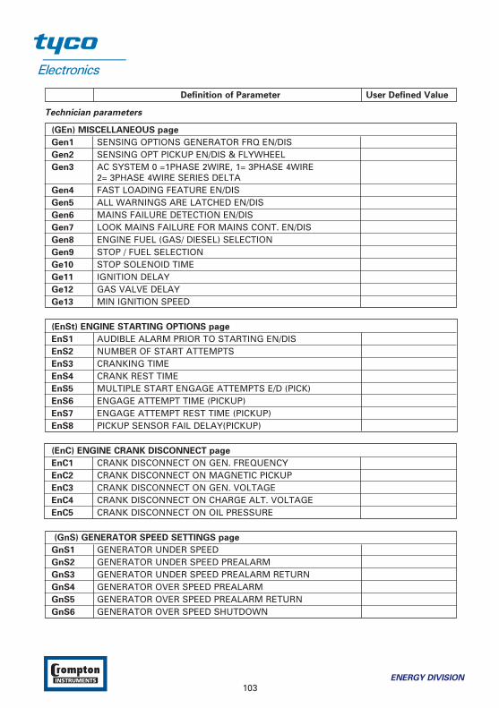
Definition of Parameter User Defined Value
Technician parameters
(GEn) MISCELLANEOUS page
Gen1 SENSING OPTIONS GENERATOR FRQ EN/DISGen2 SENSING OPT PICKUP EN/DIS & FLYWHEELGen3 AC SYSTEM 0 =1PHASE 2WIRE, 1= 3PHASE 4WIRE
2= 3PHASE 4WIRE SERIES DELTAGen4 FAST LOADING FEATURE EN/DISGen5 ALL WARNINGS ARE LATCHED EN/DISGen6 MAINS FAILURE DETECTION EN/DISGen7 LOOK MAINS FAILURE FOR MAINS CONT. EN/DISGen8 ENGINE FUEL (GAS/ DIESEL) SELECTIONGen9 STOP / FUEL SELECTIONGe10 STOP SOLENOID TIMEGe11 IGNITION DELAYGe12 GAS VALVE DELAYGe13 MIN IGNITION SPEED
(EnSt) ENGINE STARTING OPTIONS page
EnS1 AUDIBLE ALARM PRIOR TO STARTING EN/DISEnS2 NUMBER OF START ATTEMPTSEnS3 CRANKING TIMEEnS4 CRANK REST TIMEEnS5 MULTIPLE START ENGAGE ATTEMPTS E/D (PICK)EnS6 ENGAGE ATTEMPT TIME (PICKUP)EnS7 ENGAGE ATTEMPT REST TIME (PICKUP)EnS8 PICKUP SENSOR FAIL DELAY(PICKUP)
(EnC) ENGINE CRANK DISCONNECT page
EnC1 CRANK DISCONNECT ON GEN. FREQUENCYEnC2 CRANK DISCONNECT ON MAGNETIC PICKUPEnC3 CRANK DISCONNECT ON GEN. VOLTAGEEnC4 CRANK DISCONNECT ON CHARGE ALT. VOLTAGEEnC5 CRANK DISCONNECT ON OIL PRESSURE
(GnS) GENERATOR SPEED SETTINGS page
GnS1 GENERATOR UNDER SPEEDGnS2 GENERATOR UNDER SPEED PREALARM GnS3 GENERATOR UNDER SPEED PREALARM RETURNGnS4 GENERATOR OVER SPEED PREALARMGnS5 GENERATOR OVER SPEED PREALARM RETURNGnS6 GENERATOR OVER SPEED SHUTDOWN
ENERGY DIVISION
103

Definition of Parameter User Defined Value
(EnbA) ENGINE PLANT BATTERY page
Enb1 BATTERY UNDERVOLTS WARNING Enb2 BATTERY UNDERVOLTS WARNING RETURNEnb3 BATT UNDERVOLTS VOLTS DELAYEnb4 BATTERY OVERVOLTS WARNINGEnb5 BATTERY OVERVOLTS WARNING RETURN Enb6 BATT OVERVOLTS DELAYEnb7 CHARGE ALTERNATOR WARNING
(Aın) ANALOGUE INPUTS page
Aın1 OIL PRESSURE INPUT TYPEAın2 OIL PRESSURE PRE-ALARMAın3 OIL PRESSURE PRE-ALARM RETURNAın4 OIL PRESSURE SHUTDOWNAın5 TEMPERATURE INPUT TYPEAın6 TEMPERATURE PRE-ALARMAın7 TEMPERATURE PRE-ALARM RETURNAın8 TEMPERATURE SHUTDOWNAın9 LEVEL PRE-ALARMAı10 LEVEL PRE-ALARM RETURNAı11 LEVEL SHUTDOWN
104ENERGY DIVISION
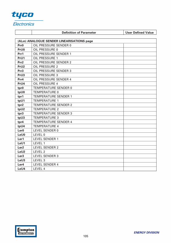
Definition of Parameter User Defined Value
(ALın) ANALOGUE SENDER LINEARISATIONS page
Prr0 OIL PRESSURE SENDER 0PrU0 OIL PRESSURE 0Prr1 OIL PRESSURE SENDER 1PrU1 OIL PRESSURE 1Prr2 OIL PRESSURE SENDER 2PrU2 OIL PRESSURE 2Prr3 OIL PRESSURE SENDER 3PrU3 OIL PRESSURE 3Prr4 OIL PRESSURE SENDER 4PrU4 OIL PRESSURE 4tpr0 TEMPERATURE SENDER 0tpU0 TEMPERATURE 0tpr1 TEMPERATURE SENDER 1tpU1 TEMPERATURE 1tpr2 TEMPERATURE SENDER 2tpU2 TEMPERATURE 2tpr3 TEMPERATURE SENDER 3tpU3 TEMPERATURE 3tpr4 TEMPERATURE SENDER 4tpU4 TEMPERATURE 4Ler0 LEVEL SENDER 0LeU0 LEVEL 0Ler1 LEVEL SENDER 1LeU1 LEVEL 1Ler2 LEVEL SENDER 2LeU2 LEVEL 2Ler3 LEVEL SENDER 3LeU3 LEVEL 3Ler4 LEVEL SENDER 4LeU4 LEVEL 4
ENERGY DIVISION
105
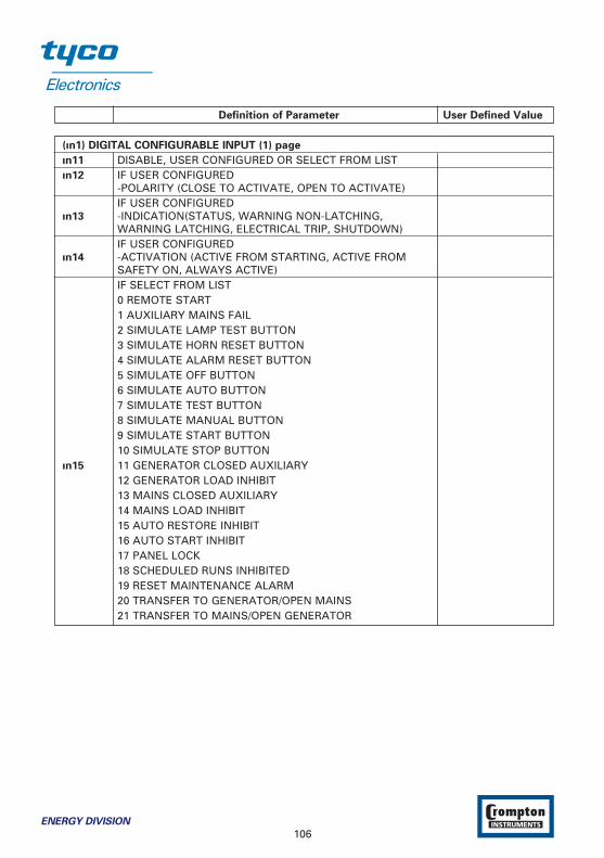
Definition of Parameter User Defined Value
(ın1) DIGITAL CONFIGURABLE INPUT (1) page
ın11 DISABLE, USER CONFIGURED OR SELECT FROM LISTın12 IF USER CONFIGURED
-POLARITY (CLOSE TO ACTIVATE, OPEN TO ACTIVATE)IF USER CONFIGURED
ın13 -INDICATION(STATUS, WARNING NON-LATCHING,WARNING LATCHING, ELECTRICAL TRIP, SHUTDOWN)IF USER CONFIGURED
ın14 -ACTIVATION (ACTIVE FROM STARTING, ACTIVE FROM SAFETY ON, ALWAYS ACTIVE)IF SELECT FROM LIST0 REMOTE START1 AUXILIARY MAINS FAIL2 SIMULATE LAMP TEST BUTTON3 SIMULATE HORN RESET BUTTON4 SIMULATE ALARM RESET BUTTON5 SIMULATE OFF BUTTON6 SIMULATE AUTO BUTTON7 SIMULATE TEST BUTTON8 SIMULATE MANUAL BUTTON9 SIMULATE START BUTTON10 SIMULATE STOP BUTTON
ın15 11 GENERATOR CLOSED AUXILIARY12 GENERATOR LOAD INHIBIT13 MAINS CLOSED AUXILIARY14 MAINS LOAD INHIBIT15 AUTO RESTORE INHIBIT16 AUTO START INHIBIT17 PANEL LOCK18 SCHEDULED RUNS INHIBITED19 RESET MAINTENANCE ALARM20 TRANSFER TO GENERATOR/OPEN MAINS21 TRANSFER TO MAINS/OPEN GENERATOR
106ENERGY DIVISION
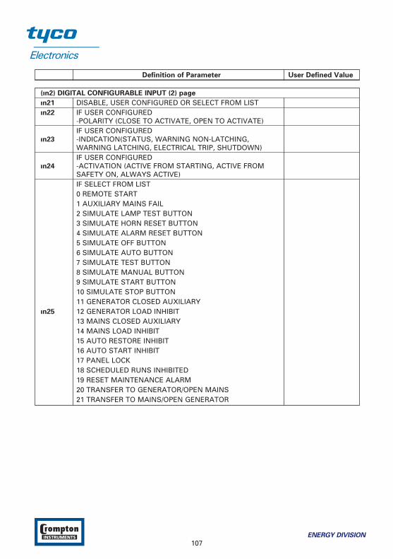
Definition of Parameter User Defined Value
(ın2) DIGITAL CONFIGURABLE INPUT (2) page
ın21 DISABLE, USER CONFIGURED OR SELECT FROM LISTın22 IF USER CONFIGURED
-POLARITY (CLOSE TO ACTIVATE, OPEN TO ACTIVATE)IF USER CONFIGURED
ın23 -INDICATION(STATUS, WARNING NON-LATCHING, WARNING LATCHING, ELECTRICAL TRIP, SHUTDOWN)IF USER CONFIGURED
ın24 -ACTIVATION (ACTIVE FROM STARTING, ACTIVE FROM SAFETY ON, ALWAYS ACTIVE)IF SELECT FROM LIST0 REMOTE START1 AUXILIARY MAINS FAIL2 SIMULATE LAMP TEST BUTTON3 SIMULATE HORN RESET BUTTON4 SIMULATE ALARM RESET BUTTON5 SIMULATE OFF BUTTON6 SIMULATE AUTO BUTTON7 SIMULATE TEST BUTTON8 SIMULATE MANUAL BUTTON9 SIMULATE START BUTTON10 SIMULATE STOP BUTTON11 GENERATOR CLOSED AUXILIARY
ın25 12 GENERATOR LOAD INHIBIT13 MAINS CLOSED AUXILIARY14 MAINS LOAD INHIBIT15 AUTO RESTORE INHIBIT16 AUTO START INHIBIT17 PANEL LOCK18 SCHEDULED RUNS INHIBITED19 RESET MAINTENANCE ALARM20 TRANSFER TO GENERATOR/OPEN MAINS21 TRANSFER TO MAINS/OPEN GENERATOR
ENERGY DIVISION
107
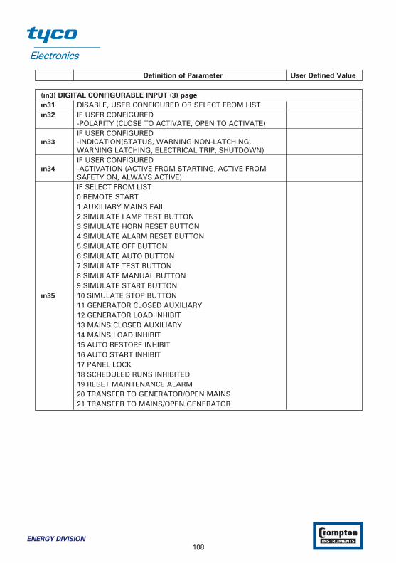
Definition of Parameter User Defined Value
(ın3) DIGITAL CONFIGURABLE INPUT (3) page
ın31 DISABLE, USER CONFIGURED OR SELECT FROM LISTın32 IF USER CONFIGURED
-POLARITY (CLOSE TO ACTIVATE, OPEN TO ACTIVATE)IF USER CONFIGURED
ın33 -INDICATION(STATUS, WARNING NON-LATCHING, WARNING LATCHING, ELECTRICAL TRIP, SHUTDOWN)IF USER CONFIGURED
ın34 -ACTIVATION (ACTIVE FROM STARTING, ACTIVE FROM SAFETY ON, ALWAYS ACTIVE)IF SELECT FROM LIST0 REMOTE START1 AUXILIARY MAINS FAIL2 SIMULATE LAMP TEST BUTTON3 SIMULATE HORN RESET BUTTON4 SIMULATE ALARM RESET BUTTON5 SIMULATE OFF BUTTON6 SIMULATE AUTO BUTTON7 SIMULATE TEST BUTTON8 SIMULATE MANUAL BUTTON9 SIMULATE START BUTTON
ın35 10 SIMULATE STOP BUTTON11 GENERATOR CLOSED AUXILIARY12 GENERATOR LOAD INHIBIT13 MAINS CLOSED AUXILIARY14 MAINS LOAD INHIBIT15 AUTO RESTORE INHIBIT16 AUTO START INHIBIT17 PANEL LOCK18 SCHEDULED RUNS INHIBITED19 RESET MAINTENANCE ALARM20 TRANSFER TO GENERATOR/OPEN MAINS21 TRANSFER TO MAINS/OPEN GENERATOR
108ENERGY DIVISION

Definition of Parameter User Defined Value
(ın4) DIGITAL CONFIGURABLE INPUT (4) page
ın41 DISABLE, USER CONFIGURED OR SELECT FROM LISTın42 IF USER CONFIGURED
-POLARITY (CLOSE TO ACTIVATE, OPEN TO ACTIVATE)IF USER CONFIGURED
ın43 -INDICATION(WARNING NON-LATCHING, WARNING LATCHING, ELECTRICAL TRIP, SHUTDOWN)IF USER CONFIGURED
ın44 -ACTIVATION (ACTIVE FROM STARTING, ACTIVE FROM SAFETY ON, ALWAYS ACTIVE)IF SELECT FROM LIST0 REMOTE START1 AUXILIARY MAINS FAIL2 SIMULATE LAMP TEST BUTTON3 SIMULATE HORN RESET BUTTON4 SIMULATE ALARM RESET BUTTON5 SIMULATE OFF BUTTON6 SIMULATE AUTO BUTTON7 SIMULATE TEST BUTTON8 SIMULATE MANUAL BUTTON9 SIMULATE START BUTTON
ın45 10 SIMULATE STOP BUTTON11 GENERATOR CLOSED AUXILIARY12 GENERATOR LOAD INHIBIT13 MAINS CLOSED AUXILIARY14 MAINS LOAD INHIBIT15 AUTO RESTORE INHIBIT16 AUTO START INHIBIT17 PANEL LOCK18 SCHEDULED RUNS INHIBITED19 RESET MAINTENANCE ALARM20 TRANSFER TO GENERATOR/OPEN MAINS21 TRANSFER TO MAINS/OPEN GENERATOR
ENERGY DIVISION
109

Definition of Parameter User Defined Value
(ın5) DIGITAL CONFIGURABLE INPUT (5) page
ın51 DISABLE, USER CONFIGURED OR SELECT FROM LISTın52 IF USER CONFIGURED
-POLARITY (CLOSE TO ACTIVATE, OPEN TO ACTIVATE)IF USER CONFIGURED
ın53 -INDICATION(WARNING NON-LATCHING, WARNING LATCHING, ELECTRICAL TRIP, SHUTDOWN)IF USER CONFIGURED
ın54 -ACTIVATION (ACTIVE FROM STARTING, ACTIVE FROM SAFETY ON, ALWAYS ACTIVE)IF SELECT FROM LIST0 REMOTE START1 AUXILIARY MAINS FAIL2 SIMULATE LAMP TEST BUTTON3 SIMULATE HORN RESET BUTTON4 SIMULATE ALARM RESET BUTTON5 SIMULATE OFF BUTTON6 SIMULATE AUTO BUTTON7 SIMULATE TEST BUTTON8 SIMULATE MANUAL BUTTON9 SIMULATE START BUTTON10 SIMULATE STOP BUTTON
ın55 11 GENERATOR CLOSED AUXILIARY12 GENERATOR LOAD INHIBIT13 MAINS CLOSED AUXILIARY14 MAINS LOAD INHIBIT15 AUTO RESTORE INHIBIT16 AUTO START INHIBIT17 PANEL LOCK18 SCHEDULED RUNS INHIBITED19 RESET MAINTENANCE ALARM20 TRANSFER TO GENERATOR/OPEN MAINS21 TRANSFER TO MAINS/OPEN GENERATOR
110ENERGY DIVISION

Definition of Parameter User Defined Value
(ın6) DIGITAL CONFIGURABLE INPUT (6) page
ın61 DISABLE, USER CONFIGURED OR SELECT FROM LISTın62 IF USER CONFIGURED
-POLARITY (CLOSE TO ACTIVATE, OPEN TO ACTIVATE)IF USER CONFIGURED
ın63 -INDICATION(WARNING NON-LATCHING, WARNING LATCHING, ELECTRICAL TRIP, SHUTDOWN)IF USER CONFIGURED
ın64 -ACTIVATION (ACTIVE FROM STARTING, ACTIVE FROM SAFETY ON, ALWAYS ACTIVE)IF SELECT FROM LIST0 REMOTE START1 AUXILIARY MAINS FAIL2 SIMULATE LAMP TEST BUTTON3 SIMULATE HORN RESET BUTTON4 SIMULATE ALARM RESET BUTTON5 SIMULATE OFF BUTTON6 SIMULATE AUTO BUTTON7 SIMULATE TEST BUTTON8 SIMULATE MANUAL BUTTON9 SIMULATE START BUTTON10 SIMULATE STOP BUTTON11 GENERATOR CLOSED AUXILIARY
ın65 12 GENERATOR LOAD INHIBIT13 MAINS CLOSED AUXILIARY14 MAINS LOAD INHIBIT15 AUTO RESTORE INHIBIT16 AUTO START INHIBIT17 PANEL LOCK18 SCHEDULED RUNS INHIBITED19 RESET MAINTENANCE ALARM20 TRANSFER TO GENERATOR/OPEN MAINS21 TRANSFER TO MAINS/OPEN GENERATOR
ENERGY DIVISION
111
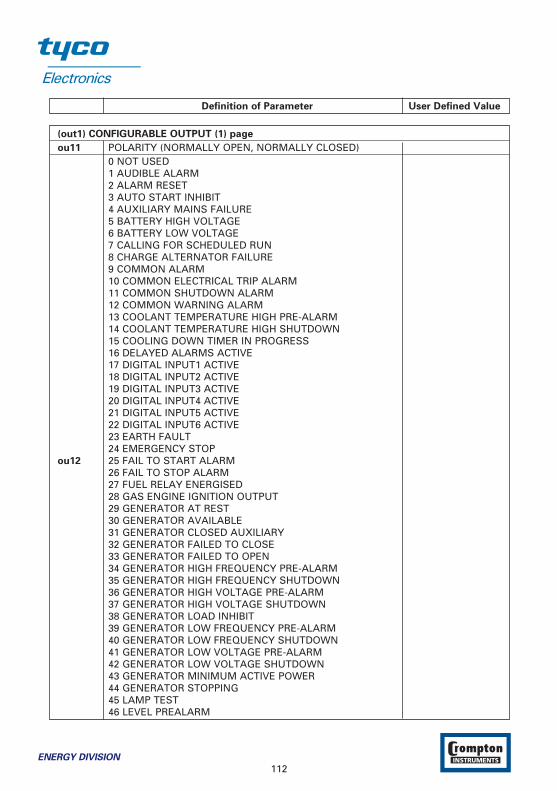
Definition of Parameter User Defined Value
(out1) CONFIGURABLE OUTPUT (1) page
ou11 POLARITY (NORMALLY OPEN, NORMALLY CLOSED)0 NOT USED1 AUDIBLE ALARM2 ALARM RESET3 AUTO START INHIBIT4 AUXILIARY MAINS FAILURE5 BATTERY HIGH VOLTAGE6 BATTERY LOW VOLTAGE7 CALLING FOR SCHEDULED RUN8 CHARGE ALTERNATOR FAILURE9 COMMON ALARM10 COMMON ELECTRICAL TRIP ALARM11 COMMON SHUTDOWN ALARM12 COMMON WARNING ALARM13 COOLANT TEMPERATURE HIGH PRE-ALARM14 COOLANT TEMPERATURE HIGH SHUTDOWN15 COOLING DOWN TIMER IN PROGRESS16 DELAYED ALARMS ACTIVE17 DIGITAL INPUT1 ACTIVE18 DIGITAL INPUT2 ACTIVE19 DIGITAL INPUT3 ACTIVE20 DIGITAL INPUT4 ACTIVE21 DIGITAL INPUT5 ACTIVE22 DIGITAL INPUT6 ACTIVE23 EARTH FAULT24 EMERGENCY STOP
ou12 25 FAIL TO START ALARM26 FAIL TO STOP ALARM27 FUEL RELAY ENERGISED28 GAS ENGINE IGNITION OUTPUT29 GENERATOR AT REST30 GENERATOR AVAILABLE31 GENERATOR CLOSED AUXILIARY32 GENERATOR FAILED TO CLOSE33 GENERATOR FAILED TO OPEN34 GENERATOR HIGH FREQUENCY PRE-ALARM35 GENERATOR HIGH FREQUENCY SHUTDOWN36 GENERATOR HIGH VOLTAGE PRE-ALARM37 GENERATOR HIGH VOLTAGE SHUTDOWN38 GENERATOR LOAD INHIBIT39 GENERATOR LOW FREQUENCY PRE-ALARM40 GENERATOR LOW FREQUENCY SHUTDOWN41 GENERATOR LOW VOLTAGE PRE-ALARM42 GENERATOR LOW VOLTAGE SHUTDOWN43 GENERATOR MINIMUM ACTIVE POWER44 GENERATOR STOPPING45 LAMP TEST46 LEVEL PREALARM
112ENERGY DIVISION

Definition of Parameter User Defined Value
(out1) CONFIGURABLE OUTPUT (1) page - continued
47 LOSS OF MAGNETIC PICK-UP SPEED SIGNAL48 MAINTENANCE DUE ALARM49 MAINS CLOSED AUXILIARY50 MAINS FAILED TO CLOSE51 MAINS FAILED TO OPEN52 MAINS FAILURE53 MAINS HIGH FREQUENCY54 MAINS HIGH VOLTAGE55 MAINS LOAD INHIBIT56 MAINS LOW FREQUENCY57 MAINS LOW VOLTAGE58 NO LOADING COMMAND59 OIL PRESSURE LOW PRE-ALARM60 OIL PRESSURE LOW SHUTDOWN61 OUTPUT TO COOLING FAN
ou12 62 OVER CURRENT63 OVERSPEED PRE-ALARM64 OVERSPEED SHUTDOWN65 PANEL LOCK66 PRE-HEAT(during preheat timer)67 PRE-HEAT(until end of cranking)68 PRE-HEAT(until end of warming)69 PRE-HEAT(until end safety on)70 REMOTE START PRESENT71 REMOTE STOP DELAY IN PROGRESS72 SHORT CIRCUIT73 START RELAY ENERGISED74 STARTING ALARM75 STARTING ALARMS ARMED76 STOP BUTTON PRESSED77 SYSTEM IN AUTO MODE78 SYSTEM IN MANUAL MODE79 SYSTEM IN OFF MODE80 SYSTEM IN TEST MODE81 UNDERSPEED SHUTDOWN82 UNDERSPEED PRE-ALARM83 WAITING FOR GENERATOR
ENERGY DIVISION
113

Definition of Parameter User Defined Value
(out2) CONFIGURABLE OUTPUT (2) page
Ou21 POLARITY (NORMALLY OPEN, NORMALLY CLOSED)0 NOT USED1 AUDIBLE ALARM2 ALARM RESET3 AUTO START INHIBIT4 AUXILIARY MAINS FAILURE5 BATTERY HIGH VOLTAGE6 BATTERY LOW VOLTAGE7 CALLING FOR SCHEDULED RUN8 CHARGE ALTERNATOR FAILURE9 COMMON ALARM10 COMMON ELECTRICAL TRIP ALARM11 COMMON SHUTDOWN ALARM12 COMMON WARNING ALARM13 COOLANT TEMPERATURE HIGH PRE-ALARM14 COOLANT TEMPERATURE HIGH SHUTDOWN15 COOLING DOWN TIMER IN PROGRESS16 DELAYED ALARMS ACTIVE17 DIGITAL INPUT1 ACTIVE18 DIGITAL INPUT2 ACTIVE19 DIGITAL INPUT3 ACTIVE20 DIGITAL INPUT4 ACTIVE21 DIGITAL INPUT5 ACTIVE22 DIGITAL INPUT6 ACTIVE23 EARTH FAULT24 EMERGENCY STOP
Ou22 25 FAIL TO START ALARM26 FAIL TO STOP ALARM27 FUEL RELAY ENERGISED28 GAS ENGINE IGNITION OUTPUT29 GENERATOR AT REST30 GENERATOR AVAILABLE31 GENERATOR CLOSED AUXILIARY32 GENERATOR FAILED TO CLOSE33 GENERATOR FAILED TO OPEN34 GENERATOR HIGH FREQUENCY PRE-ALARM35 GENERATOR HIGH FREQUENCY SHUTDOWN36 GENERATOR HIGH VOLTAGE PRE-ALARM37 GENERATOR HIGH VOLTAGE SHUTDOWN38 GENERATOR LOAD INHIBIT39 GENERATOR LOW FREQUENCY PRE-ALARM40 GENERATOR LOW FREQUENCY SHUTDOWN41 GENERATOR LOW VOLTAGE PRE-ALARM42 GENERATOR LOW VOLTAGE SHUTDOWN43 GENERATOR MINIMUM ACTIVE POWER44 GENERATOR STOPPING45 LAMP TEST46 LEVEL PREALARM
114ENERGY DIVISION
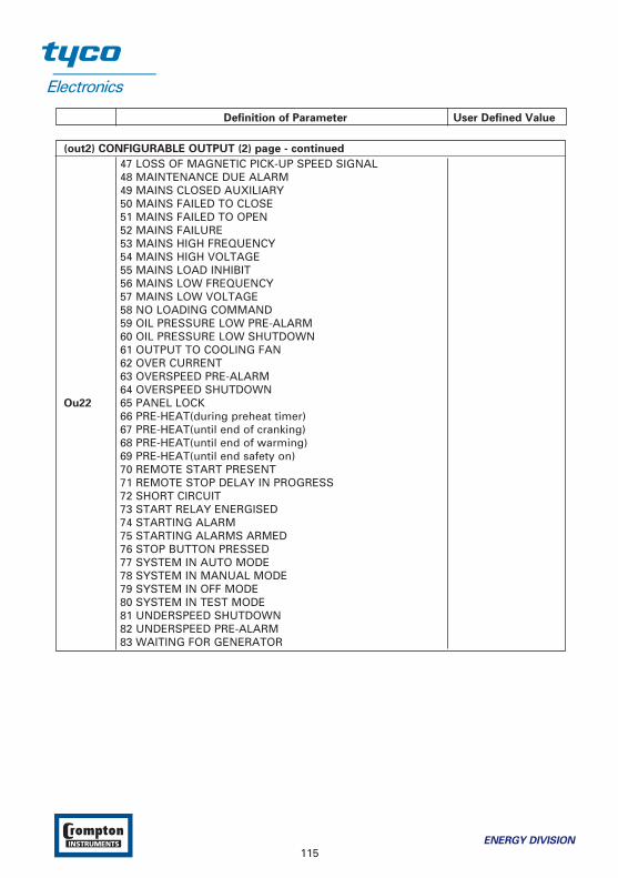
Definition of Parameter User Defined Value
(out2) CONFIGURABLE OUTPUT (2) page - continued
47 LOSS OF MAGNETIC PICK-UP SPEED SIGNAL48 MAINTENANCE DUE ALARM49 MAINS CLOSED AUXILIARY50 MAINS FAILED TO CLOSE51 MAINS FAILED TO OPEN52 MAINS FAILURE53 MAINS HIGH FREQUENCY54 MAINS HIGH VOLTAGE55 MAINS LOAD INHIBIT56 MAINS LOW FREQUENCY57 MAINS LOW VOLTAGE58 NO LOADING COMMAND59 OIL PRESSURE LOW PRE-ALARM60 OIL PRESSURE LOW SHUTDOWN61 OUTPUT TO COOLING FAN62 OVER CURRENT63 OVERSPEED PRE-ALARM64 OVERSPEED SHUTDOWN
Ou22 65 PANEL LOCK66 PRE-HEAT(during preheat timer)67 PRE-HEAT(until end of cranking)68 PRE-HEAT(until end of warming)69 PRE-HEAT(until end safety on)70 REMOTE START PRESENT71 REMOTE STOP DELAY IN PROGRESS72 SHORT CIRCUIT73 START RELAY ENERGISED74 STARTING ALARM75 STARTING ALARMS ARMED76 STOP BUTTON PRESSED77 SYSTEM IN AUTO MODE78 SYSTEM IN MANUAL MODE79 SYSTEM IN OFF MODE80 SYSTEM IN TEST MODE81 UNDERSPEED SHUTDOWN82 UNDERSPEED PRE-ALARM83 WAITING FOR GENERATOR
ENERGY DIVISION
115

Definition of Parameter User Defined Value
(out3) CONFIGURABLE OUTPUT (3) page
Ou31 POLARITY (NORMALLY OPEN, NORMALLY CLOSED)0 NOT USED1 AUDIBLE ALARM2 ALARM RESET3 AUTO START INHIBIT4 AUXILIARY MAINS FAILURE5 BATTERY HIGH VOLTAGE6 BATTERY LOW VOLTAGE7 CALLING FOR SCHEDULED RUN8 CHARGE ALTERNATOR FAILURE9 COMMON ALARM10 COMMON ELECTRICAL TRIP ALARM11 COMMON SHUTDOWN ALARM12 COMMON WARNING ALARM13 COOLANT TEMPERATURE HIGH PRE-ALARM14 COOLANT TEMPERATURE HIGH SHUTDOWN15 COOLING DOWN TIMER IN PROGRESS16 DELAYED ALARMS ACTIVE17 DIGITAL INPUT1 ACTIVE18 DIGITAL INPUT2 ACTIVE19 DIGITAL INPUT3 ACTIVE20 DIGITAL INPUT4 ACTIVE21 DIGITAL INPUT5 ACTIVE22 DIGITAL INPUT6 ACTIVE23 EARTH FAULT24 EMERGENCY STOP25 FAIL TO START ALARM
Ou32 26 FAIL TO STOP ALARM27 FUEL RELAY ENERGISED28 GAS ENGINE IGNITION OUTPUT29 GENERATOR AT REST30 GENERATOR AVAILABLE31 GENERATOR CLOSED AUXILIARY32 GENERATOR FAILED TO CLOSE33 GENERATOR FAILED TO OPEN34 GENERATOR HIGH FREQUENCY PRE-ALARM35 GENERATOR HIGH FREQUENCY SHUTDOWN36 GENERATOR HIGH VOLTAGE PRE-ALARM37 GENERATOR HIGH VOLTAGE SHUTDOWN38 GENERATOR LOAD INHIBIT39 GENERATOR LOW FREQUENCY PRE-ALARM40 GENERATOR LOW FREQUENCY SHUTDOWN41 GENERATOR LOW VOLTAGE PRE-ALARM42 GENERATOR LOW VOLTAGE SHUTDOWN43 GENERATOR MINIMUM ACTIVE POWER44 GENERATOR STOPPING45 LAMP TEST46 LEVEL PREALARM
116ENERGY DIVISION

Definition of Parameter User Defined Value
(out3) CONFIGURABLE OUTPUT (3) page - continued
47 LOSS OF MAGNETIC PICK-UP SPEED SIGNAL48 MAINTENANCE DUE ALARM49 MAINS CLOSED AUXILIARY50 MAINS FAILED TO CLOSE51 MAINS FAILED TO OPEN52 MAINS FAILURE53 MAINS HIGH FREQUENCY54 MAINS HIGH VOLTAGE55 MAINS LOAD INHIBIT56 MAINS LOW FREQUENCY57 MAINS LOW VOLTAGE58 NO LOADING COMMAND59 OIL PRESSURE LOW PRE-ALARM60 OIL PRESSURE LOW SHUTDOWN61 OUTPUT TO COOLING FAN62 OVER CURRENT63 OVERSPEED PRE-ALARM64 OVERSPEED SHUTDOWN65 PANEL LOCK
Ou32 66 PRE-HEAT(during preheat timer)67 PRE-HEAT(until end of cranking)68 PRE-HEAT(until end of warming)69 PRE-HEAT(until end safety on)70 REMOTE START PRESENT71 REMOTE STOP DELAY IN PROGRESS72 SHORT CIRCUIT73 START RELAY ENERGISED74 STARTING ALARM75 STARTING ALARMS ARMED76 STOP BUTTON PRESSED77 SYSTEM IN AUTO MODE78 SYSTEM IN MANUAL MODE79 SYSTEM IN OFF MODE80 SYSTEM IN TEST MODE81 UNDERSPEED SHUTDOWN82 UNDERSPEED PRE-ALARM83 WAITING FOR GENERATOR
ENERGY DIVISION
117

Definition of Parameter User Defined Value
(tı1) START TIMERS page
tı11 MAINS TRANSIENT DELAYtı12 REMOTE START DELAY tı13 REMOTE STOP DELAYtı14 PRE-HEATtı15 PRE-HEAT BYPASStı16 SAFETY ON DELAY tı17 HORN DURATION
(tı2) LOAD/STOPPING TIMERS page
tı21 WARMUP TIMERtı22 RETURN DELAYtı23 COOLING TIMERtı24 GENERATOR FREQUENCY ERROR CONTROL TIMEtı25 GENERATOR VOLTAGE ERROR CONTROL TIMEtı26 FAIL TO STOP TIME
(brEA) BREAKERS page
brSL HARDWARE BREAKER SELECTIONGbCC GEN CLOSE BREAKER CONTACT TYPEGbCr GEN CLOSE BREAKER RELAY TYPEGbCt GEN CLOSE TIMERGbOC GEN OPEN BREAKER CONTACT TYPEGbOr GEN OPEN BREAKER RELAY TYPEGbOt GEN OPEN TIMERMbCC MAIN CLOSE BREAKER CONTACT TYPEMbCr MAIN CLOSE BREAKER RELAY TYPEMbCt MAINS CLOSE TIMER MbOC MAIN OPEN BREAKER CONTACT TYPEMbOr MAIN OPEN BREAKER RELAY TYPEMbOt MAINS OPEN TIMER brCP BREAKER CLOSE PULSE TIMEbrOP BREAKER OPEN PULSE TIMEtrtm TRANSFER TIME
(Enm) ENGINE MAINTENANCE ALARM page
Enm1 RUNNING HOURS INTERVALEnm2 MAINTENANCE DATE INTERVALEnm3 FORCE ENGINE SHUTDOWN WHEN MAINTENANCE IS DUE EN/DISEnm4 ENGINE RUNNING HOUR (LSB)Enm5 ENGINE RUNNING HOUREnm6 ENGINE RUNNING HOUR(MSB)
118ENERGY DIVISION
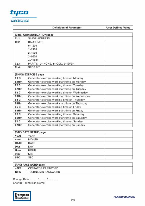
Definition of Parameter User Defined Value
(Com) COMMUNICATION page
Co1 SLAVE ADDRESSCo2 BAUD RATE
0=12001=24002=48003=96004=19200
Co3 PARITY; 0= NONE, 1= ODD, 2= EVENCo4 STOP BIT
(EHPG) EXERCISE page
E1 C Generator exercise working time on MondayE1Hm Generator exercise work start time on MondayE2 C Generator exercise working time on TuesdayE2Hm Generator exercise work start time on TuesdayE3 C Generator exercise working time on WednesdayE3Hm Generator exercise work start time on WednesdayE4 C Generator exercise working time on ThursdayE4Hm Generator exercise work start time on ThursdayE5 C Generator exercise working time on FridayE5Hm Generator exercise work start time on FridayE6 C Generator exercise working time on SaturdayE6Hm Generator exercise work start time on SaturdayE7 C Generator exercise working time on SundayE7Hm Generator exercise work start time on Sunday
(DTE) DATE SETUP page
YEAr YEARmon MONTHDATE DATEDAY DAYHour HOURmın MINSEC SEC
(PAS) PASSWORD page
oPPS OPERATOR PASSWORDtCPS TECHNICIAN PASSWORD
Change Date: . . . . . / . . . . . / . . . . . . .Change Technician Name:
ENERGY DIVISION
119

Tyco Electronics UK LimitedCrompton InstrumentsFreebournes Road, Witham,Essex, CM8 3AH, UK.Tel: +44 1376 509 509, Fax: +44 1371 509 511http://energy.tycoelectronics.com
© Tyco Electronics EPP GEN-AUTO FP & GP 01/2006
Energy Products – economical solutions for the electrical power industry: cable accessories,connectors & fittings, electrical equipment, instruments, lighting controls, insulators & insulationenhancement and surge arresters.
All of the above information, including drawings, illustrations and graphic designs, reflects our present understanding andis to the best of our knowledge and belief correct and reliable. Users, however, should independently evaluate the suitabilityof each product for the desired application. Under no circumstances does this constitute an assurance of any particular qualityor performance. Such an assurance is only provided in the context of our product specifications or explicit contractualarrangements. Our liability for these products is set forth in our standard terms and conditions of sale. CROMPTON is atrademark of Crompton Parkinson Ltd. and is used by Tyco Electronics under licence.