operating instructions thermo-gen vf portable …€¦ · operating instructions . thermo-gen vf ....
TRANSCRIPT

OPERATING INSTRUCTIONS
Thermo-Gen VF Portable Thermal Fogger
Thermo-Gen VF X-SFJR: Thermo-Gen Volumetric Fogger, Extra-Safe Junior model
Sales: 800-932-3030 • Technical Support (24/7): 800-332-6037 • Emergency: 800-535-5053
104259099 Rev. A 2012-04

Page 3 ProRestore Products
Sales: 800-932-3030 • Technical Support (24/7): 800-332-6037 • Emergency: 800-535-5053 104259099 Rev. A 2012-04
Content Ordering No.:
1. Safety instructions
2. Technical specifications
3. Technical description 4. Preparations for starting
5. Starting the engine 6. Fogging
7. Cleaning
8. Storage
9. Maintenance
10. Trouble shooting
Final content: Explosion drawings with nomenclature and order numbers EC Declaration of Conformity

Page 4 ProRestore Products
Sales: 800-932-3030 • Technical Support (24/7): 800-332-6037 • Emergency: 800-535-5053 104259099 Rev. A 2012-04
1. SAFETY INSTRUCTIONS AND ACCIDENT PREVENTION
Issued: 22-June-2011
Thermal foggers with pulse jet engines generate hot exhaust gas which may incinerate flammable objects, gases or dusts. The electrical coldfogger or ULV machines are not explosion proof as well. It is therefore mandatory to read and strictly observe the operating instructions and the safety instructions below. Failure to comply with these may result in fire or accidents. Observe the EU Directive 1999/92/EC (ATEX 137).
Intended Use The Thermo-Gen VF X-SFJR (Thermo-Gen Volumetric Fogger, Extra-Safe Junior model) is designed for fogging all kinds of pesticides, disinfectants and pest control agents authorized and approved for this type of application insofar as there are no risks for the environment, human beings and animals involved. The following type specifications must be observed:
• The Thermo-Gen VF fogger is suitable for epidemics control, plant protection in enclosed greenhouses, warehouse pest control in enclosed spaces from the outside to the inside and for the disinfection of cleaned empty animal stables with agents tested and approved for this purpose. This unit is suitable for flammable (flash point >70°C) and non-flammable fogging liquids. For safety reasons, fogging of flammable products or non-flammable products releasing oxygen (e.g. peroxides) requires using the automatic shut-off function on the unit.
• Warning: Repeated application of acidic products requires acid resistant unit versions.
Contrary to intended use
Contrary to intended use and improper handling may cause hazards for people, objects and environment. With a unintended use of the unit the general permit of operation/use expires.
Authorized Operator Groups The equipment is restricted to professional use by persons of age and qualified operators duly instructed by an authorized dealer.
WARNING: Fire Hazard Any formation of aerosols or fogs from flammable substances or acids releasing oxygen in a mixture with air and/or dust always involves the risk of fire or explosion if there is a source of ignition. The hot exhaust gas of the engine of thermal foggers is a potential source of ignition. For this reason: Make a risk analysis and develop a strategy to prevent risks! Accordingly observe strictly the following safety instructions:
y pp
All rights reserved.
Page 5 ProRestore Products
Sales: 800-932-3030 • Technical Support (24/7): 800-332-6037 • Emergency: 800-535-5053 104259099 Rev. A 2012-04
• Do not smoke when handling the unit! • Never fill fuel into the chemical tank! • Whenever fogging flammable liquids – including peroxides – into enclosed spaces,
always keep a fire extinguisher readily available near the unit. Take care the fire extinguisher is adapted to the disinfectant in use (e.g. fires caused by peroxides require an extinguishing agent based on water or CO2)
• Do not use thermal foggers to fog in rooms if there is a risk of fire, dust explosion or dust whirling up (e.g. in grain mills, non-cleaned storage silos or on floors which have not been cleaned or are covered with straw or wood dust).
• Stationary application of approved flammable agents (including peroxides) into enclosed spaces: → Only from the outside to the inside using circulating air ventilation within the room. → Only with automatic shut-off function on the unit for the disinfectant. → Ensure a stable position of the unit on a non-inflammable support.
• Observe the material safety data sheet (MSDS) and instructions of the fogging product. Check the flash point of flammable fogging liquids. Do not fog any liquids with a flash point of less than 70°C into enclosed spaces.
• Never fog more than 3 l of an approved flammable liquid or more than 10 l of a flammable aqueous liquid with a water content of less than 70 % per 1000 m³ of space!
• Never fog flammable liquids into a tube or tunnel without suction ventilation (explosion hazard).
• Do not refill fuel into the unit when the engine is still hot! The minimum cooling time is 20 minutes.
• Whenever performing any work on the carburettor or fuel tank, remove all sources of ignition from the vicinity and remove the spark plug cap and the batteries.
• CAUTION: a defective membrane (diaphragm) at the carburettor may lead to a fire accident.
Property, Operator and Environmental Protection • Observe the specified intended use of the chemical agents. In arid environments or dry
seasons and if there is a general risk of fire, only operate the unit with the built-in automatic shut-off function active. Keep a fire extinguisher readily near at the unit available.
• Observe the application instructions and safety data sheets of the manufacturer or supplier of the active substances and fogging liquids used (however, without restricting the unit manufacturer’s safety instructions in any way).
• Outdoor application is only permitted with the wind calm, or at a maximum air movement of 6 km/h. Avoid application beyond the target area by keeping a safety distance to the boundary line.
• Always use a funnel and sieve when refilling the chemical tank. Close any product drain valves before filling the chemical tank.
• Wear suitable protective clothing during the preparatory work and when fogging (full-face mask with filter A2 B2-P3, protective suit, gloves, rubber boots) as well as ear protection against the engine noise.
• The unit shall only be accessible to duly instructed persons during operation and in the cooling phase.
Prior to application: • For safety reasons the fogging valve (tap) is always closed.

Page 6 ProRestore Products
Sales: 800-932-3030 • Technical Support (24/7): 800-332-6037 • Emergency: 800-535-5053 104259099 Rev. A 2012-04
• Check the functional safety of the unit (e.g. by trial fogging with water). Repair any loose or leaking lines.
• If functional safety is not ensured, do not put the unit into operation. • The dosing nozzle and the nozzle holder (screw insert for the dosing nozzle) on the
fogging tube of the thermal foggers must be screwed hermetically tight (never omit the heat-resistant gasket).
• When filling the tanks with flammable liquids, handling a source of ignition is prohibited in the vicinity of the unit.
• In case of stationary use, ensure the stability of the unit (e.g. to prevent sliding, shaking or tilting over) on a non-flammable support.
• Make sure that the fresh air supply to the carburettor is unobstructed. Whenever fogging a flammable liquid into a room, all sources of ignition must have been removed from there and all electrical switches disconnected.
• Make sure to prevent unauthorized access to the application area (e.g. attach an access prohibition sign on the door). Close any openings of the application area and eliminate any leaks found.
During application: • Wear protective clothing (protective suit, gas mask with filter A2B2-P3, safety gloves and
ear protection). • Keep a fire extinguisher readily at hand whenever using flammable products in
enclosed spaces. Stay near the unit in order to be able to intervene immediately in an emergency.
• Never let the unit run without supervision. • Open the fogging valve only with the engine running. Close the fogging valve when the
engine is still running. In case of misuse or an accident close the tap immediately even if the motor is not running.
• The thermal fogger must not stand in the fog in an enclosed space (otherwise there is a risk that the engine could stop suddenly due to the sucking of fog into the carburettor). For this reason, keep the unit away from the fog or fog from the outside to the inside.
• If the engine should suddenly stop unexpectedly (e.g. because of a lack of fuel or energy) during application, close the fogging valve immediately and interrupt the application. Fix the problem when the unit has cooled down.
• When the chemical tank gets low (end of fogging), close the fogging valve instantly and stop the engine immediately afterwards.
• If any leakage should occur on the unit or tank during fogging, immediately 1. close the fogging valve, 2. stop the engine, 3. loose the cap of the chemical tank of the thermal fogger (depressurize the tank) and 4. terminate the application.
• Do not insert the fogging tube of an thermal fogger into another tube of similar diameter for fogging (this may result in overheating of the engine and inflammation of the fog).
• The hot fogging tube and the hot exhaust gas of a thermal fogger must never touch or reach any flammable material. For through-wall application, the minimum distance from the fogging tube surface to the wall is: 6 cm
After application: • Close and lock the fogged room and attach a warning sign.
Ventilate the treated room thoroughly before re-entering. • Close the fuel main valve of the unit

Page 7 ProRestore Products
Sales: 800-932-3030 • Technical Support (24/7): 800-332-6037 • Emergency: 800-535-5053 104259099 Rev. A 2012-04
• The fogging tube of the thermal fogger will still be hot for up to 30 minutes after stopping the engine. Do not touch the fogging tube!
• Do not transport a hot unit in an enclosed vehicle/car. • If there is any fuel or active substance left in the tanks, the unit must be kept upright
and fastened to prevent tilting and the tanks must be well closed. • Shipping of units is only admissible with the fuel tank and the rinsed chemical tank
empty. • Store in a safe place, use the original cardboard box if possible; store in a dry and dust-
free room, protected against tilting and only with the rinsed chemical tank empty. Drain the fuel tank if the unit is not going to be used for more than 3 weeks.
Regular Maintenance Required
The unit must be subjected to maintenance at regular intervals (after 50 h of operation at the latest) by a qualified person (technician), observing all applicable safety and accident prevention standards. Wear parts as well as the vibrating diaphragms of the carburettor of a thermal fogger must be replaced as described in the operating instructions by an authorized person. WARNING: Worn-out vibrating diaphragms on the carburettor not replaced in time may result in an accident involving fire. Any repairs must be made by a qualified person, at the manufacturer’s works or an authorized dealer. Warning label Heat, hot surface Use ear
protection No fire and no smoking
Read manual and safety instructions

Page 8 ProRestore Products
Sales: 800-932-3030 • Technical Support (24/7): 800-332-6037 • Emergency: 800-535-5053 104259099 Rev. A 2012-04
2. SPECIFICATIONS Model Thermo-Gen VF X-SFJR Dimensions (L × W × H) 129 × 30 × 36 cm Empty weight 7 kg Gross weight (filled tanks) 13,5 kg Capacity of chemical tank 4,5 I Capacity of fuel tank 2 I Starting current (4×1,5 V cells) 6 V DC Combustion chamber volume 300 cm³ Gross max. power of engine 17,5 kW / 24,1 h.p. / 15300 kcal/h Max. fuel consumption 1,9 I/h Flow rate with 0,8 nozzle see 6.2 Operating pressure in chemical tank 0,2–0,35 bar Max. sound pressure level during idle running 98 db Operating temperature (ambient air temperature 20 °C) on cooling jacket, max. Measured during fogging
35 °C
Temperature on cooling jacket 10 minutes after engine stop 120 °C
Temperature of combustion gas at resonator outlet when idling 550 °C
OPTIONAL EQUIPMENT
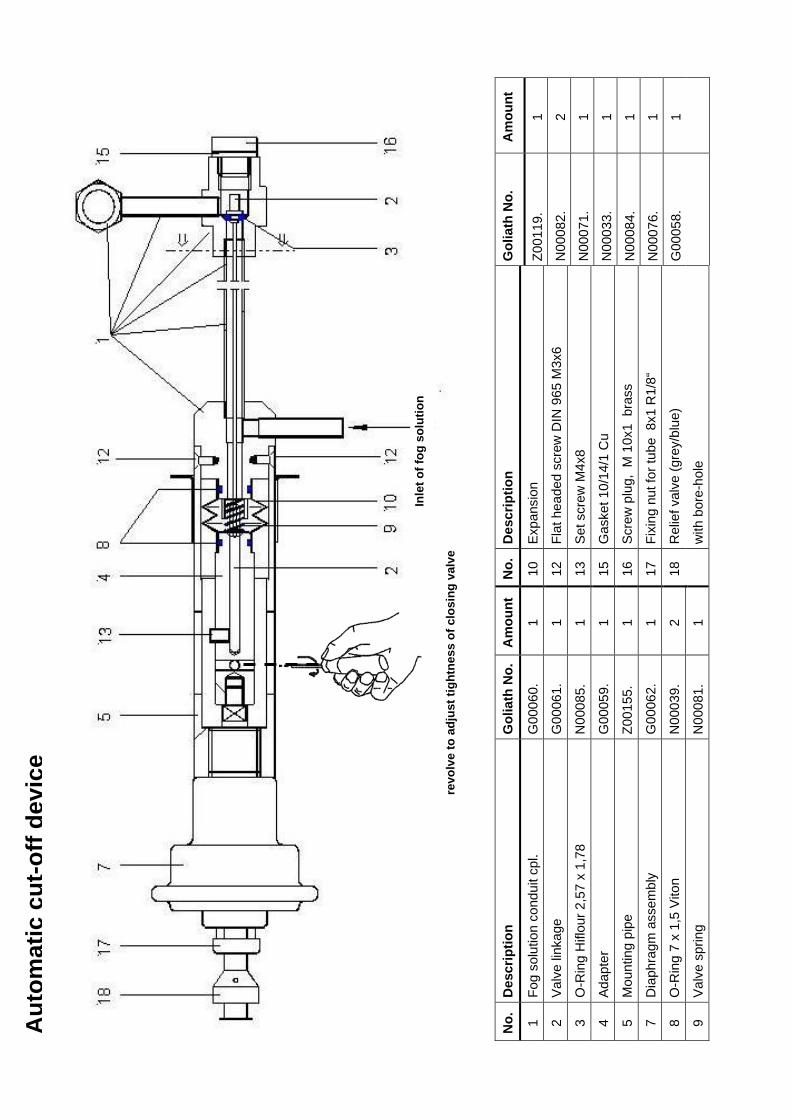
Automatic cut off device for inflammable fogging solutions Extralong protective grating Flame head Air-agitator
ACCESSORIES
Funnel for chemicals Fuel pitcher Cleaning brush for resonator Ear protectors
RECOMMENDED ACCESSORIES
Protective clothing Gas mask with filter A2B2- P3 Mixing kit cpl. consisting of: 1 stirring stick, Measure 2 ltr. Measure 0,25 ltr.
SPARE PARTS
Spare parts set with gaskets, diaphragms and 1 dosing nozzle

Page 9 ProRestore Products
Sales: 800-932-3030 • Technical Support (24/7): 800-332-6037 • Emergency: 800-535-5053 104259099 Rev. A 2012-04

Page 10 ProRestore Products
Sales: 800-932-3030 • Technical Support (24/7): 800-332-6037 • Emergency: 800-535-5053 104259099 Rev. A 2012-04
3. TECHNICAL DESCRIPTION
The unit works according to the pulse-jet principle without any mechanically moving parts. When pressing on the primer or electric starting button, a fuel/air mixture is produced in the carburettor, blown into the combustion chamber and ignited by the spark plug. A pulsating combustion forms at approximately 80 explosions per second, controlled by an air diaphragm valve and a fuel adjustable screw on the carburettor. A limited overpressure of 0,2 – 0,35 bar is redirected from the carburettor to the chemical tank through a non-return valve. The pressure in the chemical tank conveys the fogging liquid through an ON/OFF valve and a dosing nozzle to the end of the exhaust pipe. There it is injected into the exhaust stream coming from the combustion chamber. For a fraction of a second (0,05 – 0,1 s), kinetic and thermal energy (600 – 700 kcal/litre of fogging liquid) acts on the injected solution, which is thereby torn to ultra-fine aerosols. The liquid partially vaporizes and converts into a visible fog by immediate condensation in the relatively cool ambient air.

Page 11 ProRestore Products
Sales: 800-932-3030 • Technical Support (24/7): 800-332-6037 • Emergency: 800-535-5053 104259099 Rev. A 2012-04
Detailed instructions for use 4. PREPARATIONS FOR STARTING
4.1 Fill the fuel tank with pure common petrol (gasoline) of normal grade (also unleaded) but not more than 95 octane; avoid super grade fuel, if possible. The maximum filling capacity is sufficient for emptying the chemical tank. When filling in fuel, always use the graduated fuel pitcher with sieve. WARNING: Never start a fogging process with the tank less than half filled. If fuel temperature is less than 10 °C the engine may start but without powerful run. Allow the fuel to warm up to room temperature.
4.2 Run the engine briefly and stop it again (see 5.0). If the tank is less than 1/4 full, you should avoid sudden movements with the unit as far as possible and not exceed an angle of 45 upwards or downwards. Air may enter in the fuel line and interrupt the engine run.
4.3 Fill the chemical tank as follows: Open the
tank lid, remove the tube from the tank and hang it over the dosing nozzle on the fogging pipe. Release the tank holding strap and remove the chemical tank with the opening pointing upwards. The tank may only be filled with a maximum of 4,5 l. Use the funnel with sieve for filling. After filling, close tank with lid. Remount solution tank to the unit. Remove lid. Refit lid with passage and laminate gasket. WARNING: Viton hoses are not resistant to chemicals containing dichlorvos (DDVP) or Aceton as
Detaching the chemical tank
Filling the fuel tank
Detaching the chemical tank
Filling the chemical tank

Page 12 ProRestore Products
Sales: 800-932-3030 • Technical Support (24/7): 800-332-6037 • Emergency: 800-535-5053 104259099 Rev. A 2012-04
solvent. Use in that case the yellow Novoprene hoses from ProRestore. 4.4 Check tightness of dosing nozzle
WARNING: Toxic chemicals of fogging solution may be sprayed by tank pressure onto your body and face if dosing nozzle is not well sealed.
STARTING THE ENGINE
a) Set the fog tap to the closed position. b) Open the fuel adjustable screw on the
carburettor to the starting position (approx. ¼ turn).
WARNING: Opening too far would feed excessive fuel to the engine, which would cause engine and carburettor choking (flooding). Read 5.2 c. c) With your left hand press the primer
slowly down several times and each time keep it pressed for a second to prolong the ignition. Do not pump more than 5 times. Read 6.2 c.
WARNING: With the fuel tank full, do not press the primer powerfully since this would cause carburettor flooding (excessive fuel injected). Read 6.2 c
5.1 Adjusting for continuous operation After the engine has started and warmed up (approx. 30 seconds), readjust the adjustable screw on the carburettor (usually, open further) until the engine runs with a powerful, deep sound (low frequency = optimum performance). WARNING: A high sound (high-frequency engine run) means poor engine performance which causes overheating and an excessively large droplet spectrum.
A. Set the fog tap to the closed position
B. Open fuel adjustable screw approx. ¼ turn
C. With your left hand press primer slowly

Page 13 ProRestore Products
Sales: 800-932-3030 • Technical Support (24/7): 800-332-6037 • Emergency: 800-535-5053 104259099 Rev. A 2012-04
5.2 If the engine does not start → Check the fuel supply, i.e. fuel must be visible in the transparent tube between the red fuel valve and the carburettor. If no fuel is visible, continue pumping not more than 5 times. If still no fuel is becoming visible the red fuel valve may be blocked. Disconnect the valve and blow through.
→ If the carburettor is flooded of fuel
close adjustable screw and continue to pump. After some pumping (approx. 5 times) the carburettor becomes dry again and the motor tries to start. Open the adjustable screw again to the starting position and follow according to 5c. Be aware the reason of flooding of carburettor also could be a sign of a dirty spark plug.
6. FOGGING Open the fog tap while motor is running. The unit starts fogging immediately.
Note: The engine frequency may now vary
slightly under load. In this case, readjust the adjustable screw on the carburettor once more (usually, open a little more)
6.1 Interrupting the fogging process With the engine running, close the fog tap;
re-open as necessary. WARNING: Towards the end of the
fogging process, usually there is only little fuel left in the tank. Therefore you should avoid sudden movements in order to prevent air from being taken in by the fuel suction piece. A single air bubble may cause engine standstill.
6.2 Flow rate and droplet size are controlled
by interchangeable dosing (restriction)
Fogging: open the fog tap
Interchangable dosing nozzle
Fuel visible in the transparent tube

Page 14 ProRestore Products
Sales: 800-932-3030 • Technical Support (24/7): 800-332-6037 • Emergency: 800-535-5053 104259099 Rev. A 2012-04
nozzles. The flow rate depends on the unit type, the set power and the viscosity of the liquid. This should be checked on a case-to-case basis.
Fogging solution: diesel-oil Fogging solution: water Flow rate (with provided 0,8 mm dosing nozzle)
10 l/h 8,9 l/h
Other dosing nozzles upon request. Dosing nozzles with a bigger borehole permit a higher flow rate so that the produced droplet size spectrum will increase.
6.3 Stopping the fogging process Proceed in the following order:
a) Loosen the lid of the chemical tank (release pressure) and wait until the unit stops fogging.
b) Close the fog tap. c) Stop the engine (by closing the
adjustable screw on the carburettor). WARNING: When you have finished fogging, always release the solution tank from pressure first and close the fog tap before stopping the engine. Never stop the engine before the fog tap is closed! If motor stops unexpectedly during application close immediately the fogging tap and interrupt the application. Reason (In case the unit is not equipped with an automatic cut off device.): If you stop the engine before having closed the fog tap, the fogging solution remaining in the tank continues to flow to the very hot fogging pipe where it may cause fire hazard or form black sooty clouds causing dirt on the spark plug and in the carburettor. Venting the solution tank by releasing the tank lid before stopping the engine offers the additional advantage that the liquid still present in the fog solution conduits fogged off and does not remain in the conduits. WARNING: Refill fuel only with the unit cooled down. The heat radiation after stopping the
A. Loosen the lid of chemical tank (release pressure)
B. Close the fog tap before stopping the engine
C. Close adjustable screw to stop the engine

Page 15 ProRestore Products
Sales: 800-932-3030 • Technical Support (24/7): 800-332-6037 • Emergency: 800-535-5053 104259099 Rev. A 2012-04
engine will heat up the double cooling jacket of the fogging tube. Do not touch the jacket for approx. 20 minutes.

Page 16 ProRestore Products
Sales: 800-932-3030 • Technical Support (24/7): 800-332-6037 • Emergency: 800-535-5053 104259099 Rev. A 2012-04
7. CLEANING 7.1 The unit must be cleaned after each fogging application. For this purpose, remove the
solution tank and rinse it with water. Subsequently, fog approx. 1 l of clear water in order to clean the fog solution conduit. Adding a small quantity of alcohol or just a few drops of dishwashing agent is helpful.
7.2 Final cleaning
As described in section 9.1, but with additional cleaning of the carburettor diaphragm, since some fog usually penetrates the carburettor during a fogging application and may cause blocking. The carburettor diaphragm can be cleaned as follows: a) Unscrew the diaphragm valve and blow through from both sides with compressed air.
alternatively: b) Unscrew the diaphragm valve
and rinse in hot water (approx. 60 °C).
alternatively: c) Unscrew the diaphragm valve
and rinse with hand-warm water to which cleaning alcohol has been added. Cleaning with water and alcohol is especially recommended after fogging with formalin.
alternatively: d) Unscrew the diaphragm valve and put it into a vessel with fuel for 5 minutes.
Subsequently dry it with compressed air. alternatively:
e) Disassemble the valve (pictured above), clean the disassembled parts according to a), b), c) or d) and re-assemble the parts according to “Carburettor Assembly Drawing,” page 21.
8. STORAGE
If you want to keep residual quantities for a limited time in the solution tank, remove the suction tube from the tank. When the unit is not going to be used for some time, drain the fuel tank and store the unit in a cool and clean condition in the cardboard packaging. If you use the unit weekly, refill the fuel tank completely after the unit has cooled down and store it in a safe place, protected against tilting or falling down. The formation of water condensate is prevented by the tank being either completely full or completely empty!
WARNING:
Condensation in the fuel tank causes considerable malfunctions since the fuel suction piece (No. 169z) and the red fuel valve (No. 7980) will clog. Only store the

Page 17 ProRestore Products
Sales: 800-932-3030 • Technical Support (24/7): 800-332-6037 • Emergency: 800-535-5053 104259099 Rev. A 2012-04
unit in a dry and cool place, protected from direct sunlight and dust.

Page 18 ProRestore Products
Sales: 800-932-3030 • Technical Support (24/7): 800-332-6037 • Emergency: 800-535-5053 104259099 Rev. A 2012-04
9. MAINTENANCE
9.1 Cleaning the fogging pipe After fogging critical agents, or every 10 hours of operation at the latest, the resonator (exhaust pipe) should be cleaned with the cleaning brush as shown in (a).
For this purpose, the cleaning brush must be inserted into the combustion chamber over its full length (b) and then pulled out again. (c) For the K-10 model, this is facilitated by unscrewing the nozzle cane (part no. 151) slightly.
9.2 Servicing After 50 hours of engine operation, replace the diaphragm (part no. 72) on the carburettor.
a)
b)
c)

Page 19 ProRestore Products
Sales: 800-932-3030 • Technical Support (24/7): 800-332-6037 • Emergency: 800-535-5053 104259099 Rev. A 2012-04
10. Troubleshooting
Fault identified: Possible cause: Remedy: (Part nos. shown in parenthesis) 1. Engine does not start No fuel Fuel tank is empty Fill fuel tank No fuel Adjustable screw is closed Open adjustable screw No fuel reaches the carburettor when pressing the primer
Fuel nozzle is choked Clean fuel nozzle and/or blow through ring slot nozzle
No fuel is visible in the transparent hose between fuel valve and carburettor
Fuel valve sticks or is choked Fuel filter is choked
Blow through or exchange the fuel valve
Fuel in the transparent hose flows back after pumping
Red fuel valve not tight Fuel valve dirty
Exchange fuel valve or try to clean it by low air pressure
No ignition spark at the spark plug
Batteries corroded or empty, spark plug defective or wet/dirty ignition coil defect Micro-switch defective No contact between spark plug and spark plug socket
Replace batteries, exchange spark plug resp. dry/clean it. Space between electrodes of spark plug = 1,5 – 2,0 mm. Replace micro-switch/ ignition coil Fix the high-tension cable to the spark plug socket
No correct air supply through the membrane-valve
Membrane (72) is dirty and/or pasted up or assembled incorrectly
Assemble cleaned membrane-valve correctly (see drawing)

Page 20 ProRestore Products
Sales: 800-932-3030 • Technical Support (24/7): 800-332-6037 • Emergency: 800-535-5053 104259099 Rev. A 2012-04
Troubleshooting (cont.) Fault identified: Possible cause: Remedy: (Part nos. shown in parenthesis) 2. Engine runs poorly Air bubbles in the fuel Fuel pipes or fuel valve leak Tighten fuel pipes and
exchange fuel valve Fuel supply to the carburettor is not sufficient
Adjustable screw incorrectly adjusted
Turn adjustable screw to the left until the engine runs with a deep powerful sound
Air does not pass at the right measure
Membrane (72) is dirty and/or pasted up or assembled incorrectly
Clean membrane-valve and membrane resp. exchange or assemble correctly
Fuel supply is irregular Fuel nozzle is choked or destroyed by the adjustable screw
Clean fuel- and ring slot nozzle or replace fuel nozzle
Primer is blown up Block valve is defective Clean block valve, blow through or exchange it
Sparks are thrown out of the exhaust pipe
Resonator or combustion chamber is choked with chemical residues
Clean resonator and combustion chamber with cleaning brush
3. Unit fogs irregularly or not at all No pressure in chemical tank
Tank lid not tight, pressure valve (green/grey) defective
Close tank lid of chemical tank more tightly. Exchange laminate gasket (No. 119) at passage (No. 115) and replace pressure valve
Dosing nozzle(s) is (are) too hot
Idle running (without fogging) of the engine not longer than 1/2 minute
Cool down cautiously dosing nozzle(s) and nozzle cane(s) with water
No fogging solution arrives at dosing nozzle(s).
Fogging solution conduit (122z), suction piece (139), fog tap (128z) or dosing nozzle (149) choked
Clean suction piece and/or dosing nozzle and/or fog tap, blow through with compressed air. Unscrew dosing nozzle and clean nozzle cane with a small screw-driver or a wire piece.
No fogging solution arrives at dosing nozzle(s).
Viton (Novoprene) tube in chemical tank is buckled
Replace Viton (Novoprene) tube

Page 21 ProRestore Products
Sales: 800-932-3030 • Technical Support (24/7): 800-332-6037 • Emergency: 800-535-5053 104259099 Rev. A 2012-04
Carburettor Assembly Drawing

Page 22 ProRestore Products
Sales: 800-932-3030 • Technical Support (24/7): 800-332-6037 • Emergency: 800-535-5053 104259099 Rev. A 2012-04
Resonator side
Goliath No. Pos. No. Order No. Description
G00001. 1 101.100.00 Chassis K-10-SP G00280. 1 Chassis K-10-DESERT (for primer black 2-piece) Z00075. 14 900.100.01 Plastic feet G00025. 31 101.410.00 Resonator K-10-SP N00041. 46 999.009.01 Sheet head screw 3,9 x 9,5 DIN 7971 G00026. 47 101.420.00 Diffusor K-10-SP G00027. 56a 101.430.00 Cooling jacket with protective grating F00027. 57 100.433.00 Lid for cooling jacket (closed) G00028. 60 100.440.00 Holding device for cooling jacket N00090. 61 992.003.02 Clip size 80-100
G00002. 63 100.310.01 Carburettor (red) for K-10-SP cpl. with diaphragm valve, air/fuel nozzle, adjust. screw cpl., carburettor gasket, screws, nuts
Z00047. 187 900.220.01 Battery pipe Z00201. 209a 900.211.02 Spark plug cap G00035. 210 900.341.03 Primer (black, 2-piece) cpl. G00346. 210 Primer (black, 1-piece) cpl. (2 fixations) G00430. 210 Primer (black, 1 piece) cpl. (4 fixings) Z00002. 225 900.000.02 Sling N00072. 309 999.004.02 Hexagon screw M5 x 10 DIN 931 N00019. 316 997.006.03 Tooth lock washer (internal) d 5,3 DIN 6797 G00187. 101.450.00 Extralong protective grating K-10-SP G00042. 101.440.05 Holding device for extra-long protective grating (incl. No. 61)

Page 23 ProRestore Products
Sales: 800-932-3030 • Technical Support (24/7): 800-332-6037 • Emergency: 800-535-5053 104259099 Rev. A 2012-04
Fog solution tank assembly
222
Page 24 ProRestore Products
Sales: 800-932-3030 • Technical Support (24/7): 800-332-6037 • Emergency: 800-535-5053 104259099 Rev. A 2012-04
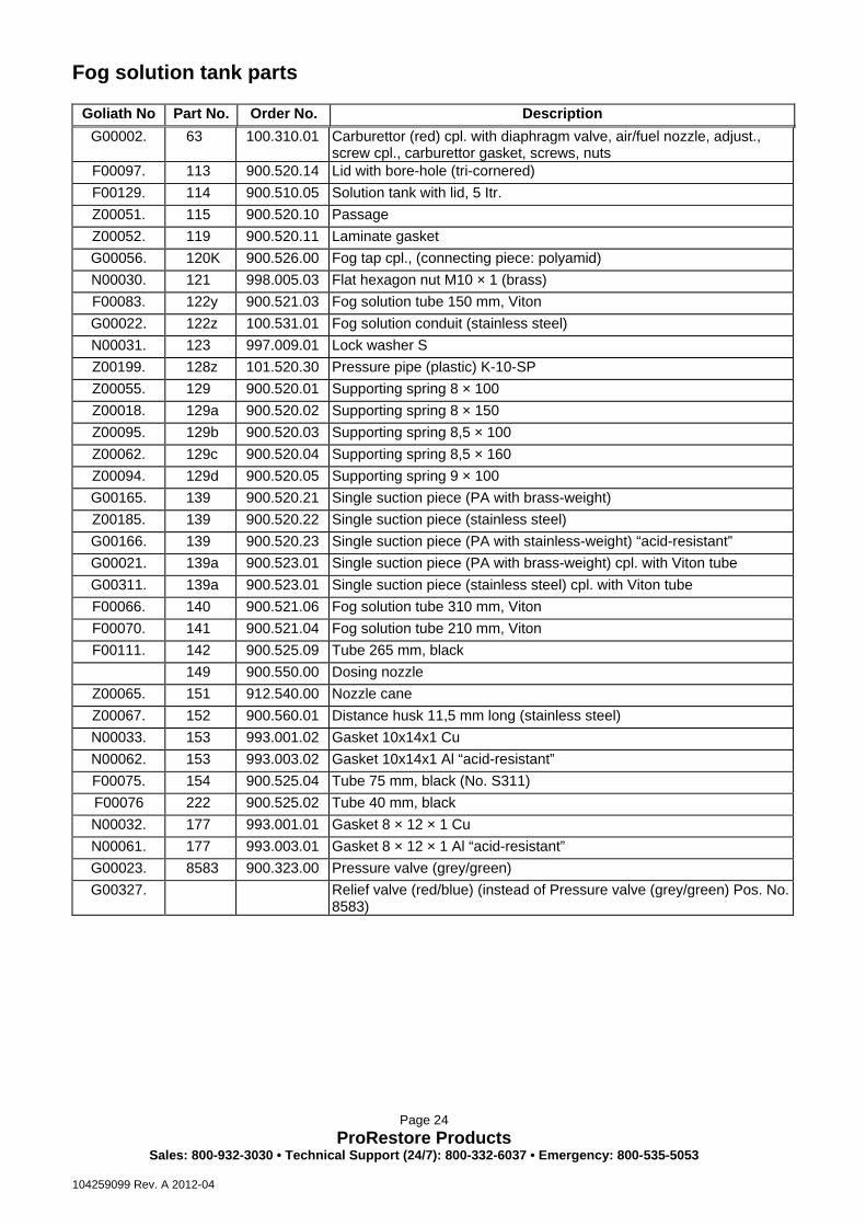
Fog solution tank parts
Goliath No Part No. Order No. Description G00002. 63 100.310.01 Carburettor (red) cpl. with diaphragm valve, air/fuel nozzle, adjust.,
screw cpl., carburettor gasket, screws, nuts F00097. 113 900.520.14 Lid with bore-hole (tri-cornered) F00129. 114 900.510.05 Solution tank with lid, 5 Itr. Z00051. 115 900.520.10 Passage Z00052. 119 900.520.11 Laminate gasket G00056. 120K 900.526.00 Fog tap cpl., (connecting piece: polyamid) N00030. 121 998.005.03 Flat hexagon nut M10 × 1 (brass) F00083. 122y 900.521.03 Fog solution tube 150 mm, Viton G00022. 122z 100.531.01 Fog solution conduit (stainless steel) N00031. 123 997.009.01 Lock washer S Z00199. 128z 101.520.30 Pressure pipe (plastic) K-10-SP Z00055. 129 900.520.01 Supporting spring 8 × 100 Z00018. 129a 900.520.02 Supporting spring 8 × 150 Z00095. 129b 900.520.03 Supporting spring 8,5 × 100 Z00062. 129c 900.520.04 Supporting spring 8,5 × 160 Z00094. 129d 900.520.05 Supporting spring 9 × 100 G00165. 139 900.520.21 Single suction piece (PA with brass-weight) Z00185. 139 900.520.22 Single suction piece (stainless steel) G00166. 139 900.520.23 Single suction piece (PA with stainless-weight) “acid-resistant” G00021. 139a 900.523.01 Single suction piece (PA with brass-weight) cpl. with Viton tube G00311. 139a 900.523.01 Single suction piece (stainless steel) cpl. with Viton tube F00066. 140 900.521.06 Fog solution tube 310 mm, Viton F00070. 141 900.521.04 Fog solution tube 210 mm, Viton F00111. 142 900.525.09 Tube 265 mm, black
149 900.550.00 Dosing nozzle Z00065. 151 912.540.00 Nozzle cane Z00067. 152 900.560.01 Distance husk 11,5 mm long (stainless steel) N00033. 153 993.001.02 Gasket 10x14x1 Cu N00062. 153 993.003.02 Gasket 10x14x1 Al “acid-resistant” F00075. 154 900.525.04 Tube 75 mm, black (No. S311) F00076 222 900.525.02 Tube 40 mm, black N00032. 177 993.001.01 Gasket 8 × 12 × 1 Cu N00061. 177 993.003.01 Gasket 8 × 12 × 1 Al “acid-resistant” G00023. 8583 900.323.00 Pressure valve (grey/green) G00327. Relief valve (red/blue) (instead of Pressure valve (grey/green) Pos. No.
8583)

Page 25 ProRestore Products
Sales: 800-932-3030 • Technical Support (24/7): 800-332-6037 • Emergency: 800-535-5053 104259099 Rev. A 2012-04
Starting installation
blue grey

Page 26 ProRestore Products
Sales: 800-932-3030 • Technical Support (24/7): 800-332-6037 • Emergency: 800-535-5053 104259099 Rev. A 2012-04
Starting installation Goliath No. Part No. Order No. Description
G00002. 63 100.310.01 Carburettor (red) cpl. with diaphragm valve, air/fuel nozzle, adjust, screw cpl., carburettor gasket, screws, nuts
G00281. 63 Carburettor (black) for K-10-DESERT cpl. (without diaphragm valve), with air/fuel nozzle, adjust. screw cpl., carburettor gasket, screws, nuts
F00093. 63b 100.310.00 Carburettor (red) body F00232. 63b Carburettor (black) body (for K-10-DESERT) Z00120. 66 100.311.01 Fuel nozzle K-10 Z00011. 67 100.311.02 Ring slot nozzle K-10 Z00008. 70 900.313.01 Support plate Z00007. 72 900.313.02 Teflon-diaphragm Z00004. 73 900.313.03 Membrane thread (diaphragm valve cap) N00004. 75 998.002.02 Counter nut M6 DIN 985 N00007. 76 993.002.01 Gasket 6 × 12 × 1 Fi Z00014. 78 900.310.01 Carburettor gasket (Abil) N00093. 91 999.004.06 Hexagon head screw M6 × 20 DIN 931 N00010. 92 997.005.04 Tooth lock washer (external) d 6,4 DIN 6797 N00011. 93 998.001.06 Hexagon nut M6 DIN 934 N00015. 94 992.001.02 Tube clip (size 8) F00114. 96y 923.353.01 Fuel tube (blue) N00014. 97 992.001.03 Tube clip (size 9) G00007. 103a 900.312.03 Knurled washer cpl. N00071. 103b 999.007.01 Locking screw M4 × 8 DIN 551 G00008. 103c 900.312.01 Threaded spindle G00006. 103z 900.312.00 Adjustable screw cpl. with O-ring N00063. 110 993.005.01 O-ring N00006. 111 900.311.03 Ring piece F00151. 165 912.351.01 Fuel tank with bore-holes and lid (d 32 mm) G00010. 165/1 100.352.00 Fuel tank with fuel valve cpl. Z00025. 165a 900.350.01 Lid for fuel tank (d 32 mm) G00012. 166z 900.354.03 Connecting piece (bent) Z00152. 168 900.354.04 Aeration piece Z00027. 169z 900.354.01 Fuel suction piece F00081. 170 900.354.02 Fuel suction tube, Viton N00013. 174z 998.005.04 Hexagon nut (flat) M10 × 1,75 (brass) N00012. 175 998.005.02 Hexagon nut (flat) M8 (brass) N00005. 176 993.002.02 Gasket 10 × 14 × 1 Fi F00082. 178 900.525.05 Tube 85 mm, black F00076. 222 900.525.02 Air tube 40 mm, black G00235. S301 912.331.00 Block valve (grey/grey/blue) G00004. S302 900.313.04 Starting nozzle F00113. S310 900.355.02 Tube 40 mm, transparent F00075. S311 900.525.04 Tube 75 mm, black G00014. 7980 900.321.01 Fuel valve (red) with transparent tube G00013. 7980a 923.321.02 Fuel valve (red) cpl. with tubes G00023. 8583 900.323.00 Pressure valve (grey/green)

Page 27 ProRestore Products
Sales: 800-932-3030 • Technical Support (24/7): 800-332-6037 • Emergency: 800-535-5053 104259099 Rev. A 2012-04

Page 28 ProRestore Products
Sales: 800-932-3030 • Technical Support (24/7): 800-332-6037 • Emergency: 800-535-5053 104259099 Rev. A 2012-04
Primer and ignition installation
4-point fixing 2-point fixing

Page 29 ProRestore Products
Sales: 800-932-3030 • Technical Support (24/7): 800-332-6037 • Emergency: 800-535-5053 104259099 Rev. A 2012-04
Primer and ignition installation
Goliath No. Pos. No. Order No. Description
Z00041. 183 900.211.01 Ignition device Z00042. 184 900.210.00 Micro - switch Z00043. 185 900.221.00 Battery 1,5 V Z00044. 186 900.212.00 Spark plug F00010. 188 900.220.02 Lid for battery pipe N00022. 193 999.008.01 Butterfly screw M5 × 10 DIN 316 N00021. 197 999.001.02 Fillister head screw M3 × 20 DIN 84 N00023. 198 998.001.01 Hexagon nut M3 DIN 934 N00020. 199 998.001.05 Hexagon nut M5 DIN 934 N00024. 200 997.003.01 Spring washer M3 DIN 127A G00019. 202 900.220.00 Contact piece with cable Z00046. 205 900.210.01 Rubber washer 45 × 30 × 3 N00027. 207 999.001.07 Fillister head screw M5 × 6 (brass) N00019. 209 997.006.03 Tooth lock washer (internal) d 5,3 DIN 6797 Z00201. 209a 900.211.02 Spark plug cap G00035. 210 900.341.03 Primer (black, 2-piece) cpl. rubber G00346. 210 Primer (black, 1-piece) cpl. (2 fixings) G00430. 210 Primer (black, 1 piece) cpl. (4 fixings) F00338. 210a Primer (black, 1-piece), body (2 fixings) F00400. 210a Primer (black, 1-piece), body (4 fixings) G00036. 210a 900.341.00 Primer (black, 2-piece), body rubber Z00079. 900.341.01 Primer (black, 2-piece) – bottom part rubber Z00078. 900.341.02 Primer (black, 2-piece) – top part rubber Z00039. 212 900.342.01 Connection piece M 12 (for primer black, 1-piece) Z00080. 212 Connection piece M 8 (for primer black, 2-piece) N00068. 213 999.005.01 Flat headed screw M5 × 10 DIN 921 (for primer black, 1-piece) N00047. 213 999.005.02 Flat headed screw M5 × 16 DIN 921 (for primer black, 2-piece) N00017. 216 998.005.05 Hexagon nut M 12, flat (for primer black, 1-piece) N00012. 216 Hexagon nut M 8, flat (for primer black, 2-piece) Z00040. 217 900.342.02 Plastic washer Ø13 (for primer black, 1-piece) Z00081. 217 Plastic washer Ø8 (for primer black, 2-piece) F00148. 223 900.342.04 Diaphragm for non-return valve (for primer) Z00038. 223a 900.342.03 Non-return valve without diaphragm (for primer) G00017. 223b 900.342.05 Non-return valve with diaphragm (for primer) N00042. 226 999.004.04 Hexagon screw M5 × 30 DIN 931
Am
ount
1 2 1 1 1 1 1
Gol
iath
No.
Z001
19.
N00
082.
N00
071.
N00
033.
N00
084.
N00
076.
G00
058.
Des
crip
tion
Expa
nsio
n
Flat
hea
ded
scre
w D
IN 9
65 M
3x6
Set s
crew
M4x
8
Gas
ket 1
0/14
/1 C
u
Scre
w p
lug,
M 1
0x1
bra
ss
Fixi
ng n
ut fo
r tub
e 8
x1 R
1/8“
Rel
ief v
alve
(gre
y/bl
ue)
with
bor
e-ho
le
No.
10
12
13
15
16
17
18
Am
ount
1 1 1 1 1 1 2 1
Gol
iath
No.
G00
060.
G00
061.
N00
085.
G00
059.
Z001
55.
G00
062.
N00
039.
N00
081.
Des
crip
tion
Fog
solu
tion
cond
uit c
pl.
Valv
e lin
kage
O-R
ing
Hifl
our 2
,57
x 1,
78
Adap
ter
Mou
ntin
g pi
pe
Dia
phra
gm a
ssem
bly
O-R
ing
7 x
1,5
Vito
n
Valv
e sp
ring
No.
1 2 3 4 5 7 8 9
Inle
t of f
og s
olut
ion
revo
lve
to a
djus
t tig
htne
ss o
f clo
sing
val
ve
Aut
omat
ic c
ut-o
ff de
vice
