installation and operating guide - leviton.com
TRANSCRIPT
Installation and Operating Guide
MDS DIMMER CABINETS WITH LUMA-NET® CONTROLSoftware revision 1.01 and above
Installation and Operating Guide
Leviton MDS Dimmer Cabinets with Luma-Net Control ii
Table of Contents
OVERVIEW
Description............................................................................... 1Inspection................................................................................ 1Mounting ................................................................................. 1
Surface Mount ................................................................ 1Freestanding .................................................................. 2
Power Wiring............................................................................ 2Control Wiring .......................................................................... 2Fluorescent Wiring .................................................................... 2Turn On ................................................................................... 2Modules ................................................................................... 3Checklist .................................................................................. 3
INITIAL SETUP AND INSTALLATION
Inspection................................................................................ 4Mounting ................................................................................. 4
Surface Mount ................................................................ 4Freestanding .................................................................. 4
Power Wiring............................................................................ 4Emergency Power Wiring .......................................................... 4Control Wiring .......................................................................... 5Fluorescent Wiring .................................................................... 5Neon and Cold Cathode Dimming............................................... 5Turn On ................................................................................... 6Modules ................................................................................... 6Module Configuration ................................................................ 6Digital Control Panel ................................................................. 7
Luma-Net® III ............................................................... 7DMX-512........................................................................ 7Analog ........................................................................... 7Multiple Signal Types ...................................................... 7
Readouts and Indicators ........................................................... 8LCD Display.................................................................... 8Programming Buttons ..................................................... 8LED Indicators................................................................ 9Navigation Buttons.......................................................... 9
Fluorescent Dimming ................................................................ 90-10 VDC Controlled Ballasts ........................................... 9Two-Wire Fluorescent Ballasts ....................................... 10
Other Ballasts......................................................................... 10
Installation and Operating Guide
Leviton MDS Dimmer Cabinets with Luma-Net Control iii
CONFIGURATION AND PROGRAMMING
Overview ............................................................................... 11Dimmer Configuration in the Field............................................ 11Basic Dual Dimmer Module DI21-120U ..................................... 11Three More Module Configurations........................................... 12
DND20/126-1 ............................................................... 12XDND20/126-1 ............................................................. 12F20-120U/136-1 ........................................................... 12
Checking the Module Programming in a Dimmer Cabinet ........... 12Dimmer Types........................................................................ 13Changing a Module Type......................................................... 14Assigning Luma-Net and/or DMX512 Channels .......................... 15
Assigning Numbers Automatically................................... 15Assigning Individual Channels........................................ 16
Specifications ......................................................................... 17
WARRANTY INFORMATION
Warranty................................................................................ 18
Installation and Operating Guide
Leviton MDS Dimmer Cabinets with Luma-Net Control Page 1 of 1818
Overview
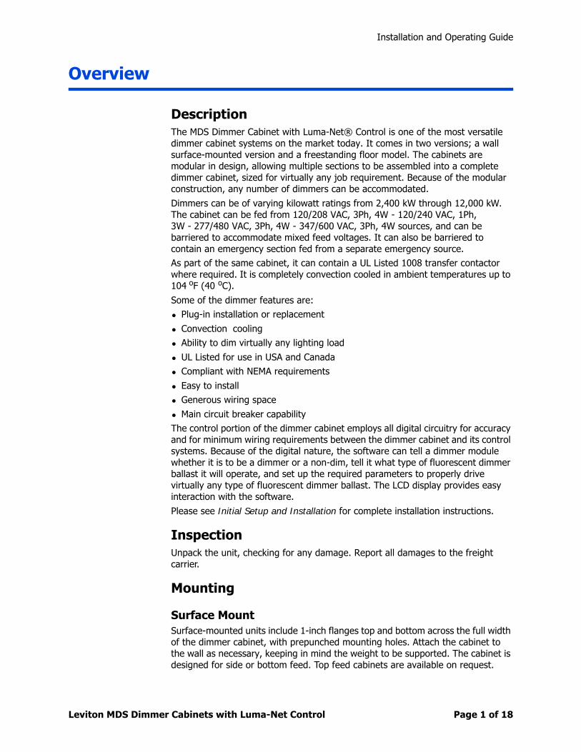
DescriptionThe MDS Dimmer Cabinet with Luma-Net® Control is one of the most versatile dimmer cabinet systems on the market today. It comes in two versions; a wall surface-mounted version and a freestanding floor model. The cabinets are modular in design, allowing multiple sections to be assembled into a complete dimmer cabinet, sized for virtually any job requirement. Because of the modular construction, any number of dimmers can be accommodated.
Dimmers can be of varying kilowatt ratings from 2,400 kW through 12,000 kW. The cabinet can be fed from 120/208 VAC, 3Ph, 4W - 120/240 VAC, 1Ph, 3W - 277/480 VAC, 3Ph, 4W - 347/600 VAC, 3Ph, 4W sources, and can be barriered to accommodate mixed feed voltages. It can also be barriered to contain an emergency section fed from a separate emergency source.
As part of the same cabinet, it can contain a UL Listed 1008 transfer contactor where required. It is completely convection cooled in ambient temperatures up to 104 oF (40 oC).
Some of the dimmer features are:
• Plug-in installation or replacement
• Convection cooling
• Ability to dim virtually any lighting load
• UL Listed for use in USA and Canada
• Compliant with NEMA requirements
• Easy to install
• Generous wiring space
• Main circuit breaker capability
The control portion of the dimmer cabinet employs all digital circuitry for accuracy and for minimum wiring requirements between the dimmer cabinet and its control systems. Because of the digital nature, the software can tell a dimmer module whether it is to be a dimmer or a non-dim, tell it what type of fluorescent dimmer ballast it will operate, and set up the required parameters to properly drive virtually any type of fluorescent dimmer ballast. The LCD display provides easy interaction with the software.
Please see Initial Setup and Installation for complete installation instructions.
InspectionUnpack the unit, checking for any damage. Report all damages to the freight carrier.
Mounting
Surface MountSurface-mounted units include 1-inch flanges top and bottom across the full width of the dimmer cabinet, with prepunched mounting holes. Attach the cabinet to the wall as necessary, keeping in mind the weight to be supported. The cabinet is designed for side or bottom feed. Top feed cabinets are available on request.
Installation and Operating Guide
Leviton MDS Dimmer Cabinets with Luma-Net Control Page 2 of 1818
FreestandingFreestanding floor units are 90 inches tall by 20 inches deep overall, with the width determined by the number of cabinet sections necessary to suit a particular job requirement. Generally both freestanding and flush-mounted cabinets are designed for side or bottom feed. Top feed cabinets are available on request.
Power WiringThe cabinet includes:
• Main lugs for phases A, B, and C (or A and B in the case of a single-phase cabinet)
• A load terminal block to land all the dimmer output load wiring. Where a single dimmer feeds multiple load circuits output load wiring lands on the associated branch circuit breaker terminals.
• A multi-terminal neutral block
• A single ground terminal
An optional multiple-terminal ground bus is available; call the factory and ask for part number HDW-32096-00. The main lugs are sized for every dimmer to be loaded to maximum capacity. You may elect to size the feed to the actual connected load on the cabinet.
Control WiringTypically the left portion of the dimmer cabinet is reserved for control wiring. Refer to the installation diagrams that are shipped with the dimmer cabinet. Terminate all control wiring to the terminal blocks provided. Use a small 1/8-in. flat screwdriver on these terminals.
Fluorescent Wiring Some fluorescent dimmer ballasts use three power wires; a neutral, a switched hot, and a line voltage control wire.
Some fluorescent dimmer ballasts require only two power wires; one hot circuit wire that is both dimmed and switched, and one neutral wire.
Some dimmer ballasts require line and neutral plus two low voltage control wires. Make sure the dimmer ballasts on this project are correctly wired prior to turn on.
Incorrect wiring of these ballasts to dimmers can damage the ballasts.
Turn OnPrior to turn on, verify the following:
• Main feed wiring
• Load wiring
• Remote control wiring
• Configuration of each module with the type of load connected and any ballast control wiring
Installation and Operating Guide
Leviton MDS Dimmer Cabinets with Luma-Net Control Page 3 of 1818
ModulesEach of the dimmer modules are held in place by four mounting screws.
To change a dimmer:
1 Turn off all power to the dimmer cabinet.
2 Remove the four screws that hold the dimmer in place.
3 Pull the module forward sufficiently to unplug the power and control connectors.
To install a new unit:
1 Insert the dimmer partially in the cabinet.
2 Plug the power and control connectors into the rear of the replacement dimmer.
3 Insert the dimmer into the cabinet.
4 Reuse the four mounting screws to hold the dimmer in place.
By using multi-pin connectors for both power and control wiring, there is no risk of crossed wires when hooking up a new module.
If it is not possible to shut down the entire cabinet, turn off the circuit breakers feeding the dimmer modules above and below the new module.
ChecklistUnpack the system
Report any damages
Attach any surface mounted cabinets to the wall
Set freestanding floor cabinets in place
Terminate control wiring
Make sure that any dimmer ballasts are correctly wired
Verify the main feed wiring
Verify the load wiring
Verify the remote control wiring
Verify the configuration of each module
Installation and Operating Guide
Leviton MDS Dimmer Cabinets with Luma-Net Control Page 4 of 1818
Initial Setup and Installation
InspectionCarefully unpack the dimmer system, and inspect to make sure there has been no hidden shipping damage. Report all damage to the freight carrier who delivered the system. Claims for damages are filed with the freight carrier as all freight is shipped FOB Tualatin, Oregon. The MDS dimmer cabinet can be serviced in the field with replacement factory components in case of damaged parts.
Mounting
Surface MountSurface-mounted units include a 1-in. flange top and bottom across the full width of the dimmer cabinet with prepunched mounting holes. Attach the cabinet to the wall as necessary, keeping in mind the weight to be supported. Leviton recommends that cabinet mounting hardware reaches through the wall and attaches to the wall studs. However properly sized struts and suitable hardware can be used. The cabinets are heavy, and should not exceed the anchor limits. The cabinet is designed for side or bottom feed. Top feed cabinets are available on request.
FreestandingFreestanding floor units are 90 in. tall by 20 in. deep overall, with the width determined by the number of cabinet sections necessary to suit a particular job requirement. Generally both floor and surface-mounted cabinets are designed for side or bottom feed. Top feed cabinets are available on request.
Power WiringThe cabinet includes:
• Main lugs for phases A, B, and C (or A and B in the case of a single-phase cabinet)
• A load terminal block to land all the dimmer output load wiring. Where a single dimmer feeds multiple load circuits output load wiring lands on the associated branch circuit breaker terminals.
• A multi-terminal neutral block
• A single ground terminal
An optional multiple-terminal ground bus is available; call the factory and ask for part number HDW-32096-00. The main lugs are sized for every dimmer to be loaded to maximum capacity. You may elect to size the feed to the actual connected load on the cabinet.
Emergency Power WiringDepending on job requirements there may be an barriered section within the cabinet that contains emergency dimmers, contactors, power supplies and other equipment as needed. This section can assure that full power from an emergency source is fed to certain circuits designated as emergency circuits.
Installation and Operating Guide
Leviton MDS Dimmer Cabinets with Luma-Net Control Page 5 of 1818
This section will include:
• Main lugs for emergency phases A, B, and C (or A and B in the case of a single phase emergency system)
• Emergency power, which can be 120/208VAC, or 277/480VAC depending upon the power requirements for the entire job
• Load terminal block to land all the dimmer output load wiring
• A multi-terminal neutral block
• Bypass relays to bring the power to full brightness in case of power outages of the normal power feeds
• A UL 1008 transfer contactor if specified
If bypass contactors are used, each dimmer will have a normally closed bypass contactor in parallel with it. This bypass contactor is held in the open position by power from the normal power sources and the control power. Should any of these normal power sources fail, the bypass contactors fall shut, supplying full power to the emergency load circuits until normal power returns. When normal power returns they are held open again, and normal dimming operation of the emergency circuits resumes where it left off.
Control WiringTypically the left portion of the dimmer cabinet is reserved for control wiring. Refer to the installation diagrams that are shipped with the dimmer cabinet. Terminate all control wiring to the terminal blocks provided. Use a small 1/8-in. flat screwdriver on these terminals.
Fluorescent Wiring Some fluorescent dimmer ballasts use three power wires; a neutral, a switched hot, and a line voltage control wire.
Some fluorescent dimmer ballasts require only two power wires; one hot circuit wire that is both dimmed and switched and one neutral wire.
Some dimmer ballasts require line and neutral plus two low voltage control wires.
Double check the wiring to the dimmer output terminals that feed the dimmer ballasts before turning on any power; these ballasts can be adversely affected if the line voltage control wire and the switched line connections are reversed. Some dimmer ballasts require line and neutral plus two low voltage control wires. Make sure the dimmer ballasts are correctly wired prior to turn on.
Neon and Cold Cathode DimmingThe dimmers are capable of dimming both neon and cold cathode. In both cases the transformers used to step up the voltage for the tubes must be of the low power factor type (sometimes called normal power factor types). Using power factor corrected type stepup transformers will result in poor dimming. There are certain types of solid state stepup transformers available for Neon and Cold Cathode operation. These are normally not designed to be dimmed; attempting to dim them may result in harm to the solid state transformers. Check with the manufacturer of these transformers for suitability before connecting them to dimmers in this system. It is generally recommended that a transformer with an
Installation and Operating Guide
Leviton MDS Dimmer Cabinets with Luma-Net Control Page 6 of 1818
output voltage rating about 1.5 times that normally chosen for a given tubing diameter and fill be used to insure good dimming throughout the range.
Turn OnPrior to turn on, verify the following:
• Main feed wiring
• Load wiring
• Remote control wiring
• Correct wiring to any fluorescent dimmer ballasts
• Configuration of each module with the type of load connected and any ballast control wiring
With all power and control wiring in place, and all dimmer modules installed and properly configured, the system is ready for turn on.
ModulesEach of the dimmer modules are held in place by four mounting screws.
To change a dimmer:
1 Turn off all power to the dimmer cabinet
2 Remove the four screws that hold the dimmer in place.
3 Pull the module forward sufficiently to unplug the power and control connectors.
To install a new unit:
1 Plug in the power and control connectors.
2 Insert the dimmer partially into the cabinet.
3 Plug the power and control connectors into the rear of the replacement dimmer.
4 Insert the dimmer the rest of the way into the cabinet.
5 Reuse the four mounting screws to hold the dimmer in place.
By using multi pin connectors for both power and control there is no risk of crossed wires when hooking up a new module.
Module ConfigurationPrior to turn on, carefully check the as-built prints shipped with the cabinet. The dimmer modules in the cabinet are arranged in order just as they are shown on these prints. If there have been changes to the job site loads that do not agree with the as-built prints, modifications to the modules or their positions in the cabinet could be necessary.
Verify that each module is wired to the load as shown on these drawings. If the dimmer modules are driving the wrong load circuits, damage can occur to certain types of dimmer ballasts. Some ballasts are adversely affected if the dimmed and switched connections are reversed.
Installation and Operating Guide
Leviton MDS Dimmer Cabinets with Luma-Net Control Page 7 of 1818
Digital Control Panel The digital control panel in this cabinet is equipped with a powerful microprocessor to make this a multifunctional system. It can accept several types of input signals, depending on the exact configuration.
Luma-Net® IIIThe most common input is Luma-Net III, a Leviton protocol, that sends serial digital data over a twisted pair of communication (data) wires. With this system, controls can be located up to 2000 ft from the dimming cabinet. The two data wires terminate on REM+ and REM- of the Luma-Net Terminal Block. Any shield if present is not connected.
Along with this pair of communications (data) wires are a second pair of wires for providing current limited 12 VDC power to operate displays and electronics in the remote control stations. These wires terminate on COM and +V. The communications signals require very little power, and number 24 AWG wire is adequate for the twisted pair. Belden number 9729 or equivalent is recommended. However the 12 VDC power wires handle more current and should be a minimum of 14 AWG size wire to insure that only a very small amount of voltage drop takes place over long distances. If a remote DC power supply is used, all DC common wires must be joined.
Where more than one remote control panel or dimmer cabinet using Luma-Net III communications is used in a system, the data wires and the DC power wires are run together from the dimmer cabinet to the nearest control station, then on to the next station, and the next, and so on. At the last control station or dimmer cabinet on both ends of the run, a small jumper wire must be run from the terminal labeled “Rem-” to the terminal marked “Term” on that last station. This jumper wire properly terminates the digital communications lines at the end of the line.
DMX-512The digital control panel accepts DMX-512 signals, an industry standard signal widely used in the theater industry. This offers the opportunity to use small theatrical consoles to control some or all of the dimmers in the MDS Dimmer Cabinet.
AnalogThe digital control panel accepts a third type of control signal often used with analog control systems, if equipped with the optional DC Control Card. This signal varies between 0 VDC and +10 VDC to control the dimmer outputs. An input of 0 V results in no output power from the dimmer; an input of +10 VDC gives full voltage output from the dimmer. Varying this signal from 0 VDC to +10 VDC varies the AC output voltage from zero to virtually full line voltage. If this system uses analog inputs, an optional DC Control circuit card will have been added during fabrication within the control cards assembly.
Multiple Signal TypesUnder certain circumstances the digital control panel can receive two or more types of input signals. The output from each dimmer is determined by the highest input signal it receives from the different sources.
Installation and Operating Guide
Leviton MDS Dimmer Cabinets with Luma-Net Control Page 8 of 1818
Input terminals for RS485 and RS232 signals direct from a computer can be used in programming the digital control panel. There are also terminals reserved for future use with a communications protocol called Canbus.
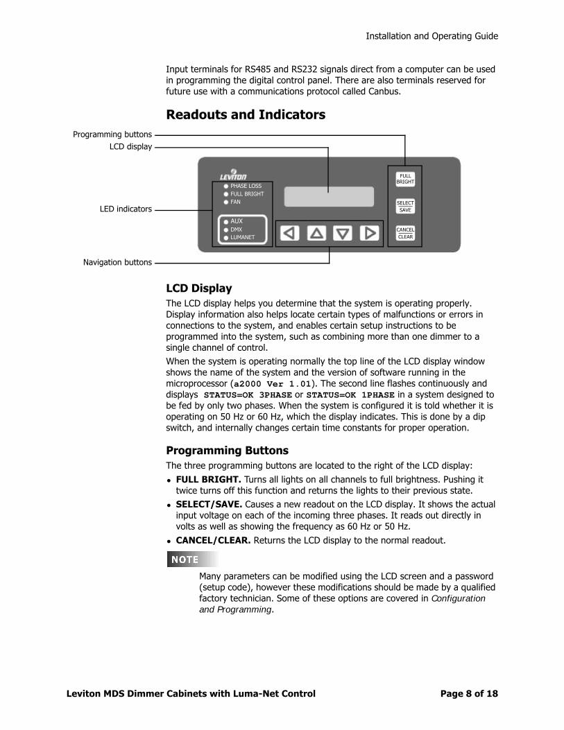
Readouts and Indicators
LCD DisplayThe LCD display helps you determine that the system is operating properly. Display information also helps locate certain types of malfunctions or errors in connections to the system, and enables certain setup instructions to be programmed into the system, such as combining more than one dimmer to a single channel of control.
When the system is operating normally the top line of the LCD display window shows the name of the system and the version of software running in the microprocessor (a2000 Ver 1.01). The second line flashes continuously and displays STATUS=OK 3PHASE or STATUS=OK 1PHASE in a system designed to be fed by only two phases. When the system is configured it is told whether it is operating on 50 Hz or 60 Hz, which the display indicates. This is done by a dip switch, and internally changes certain time constants for proper operation.
Programming ButtonsThe three programming buttons are located to the right of the LCD display:
• FULL BRIGHT. Turns all lights on all channels to full brightness. Pushing it twice turns off this function and returns the lights to their previous state.
• SELECT/SAVE. Causes a new readout on the LCD display. It shows the actual input voltage on each of the incoming three phases. It reads out directly in volts as well as showing the frequency as 60 Hz or 50 Hz.
• CANCEL/CLEAR. Returns the LCD display to the normal readout.
Many parameters can be modified using the LCD screen and a password (setup code), however these modifications should be made by a qualified factory technician. Some of these options are covered in Configuration and Programming.
PHASE LOSS
AUX
FULL BRIGHTFAN
DMXLUMANET
FULLBRIGHT
SELECTSAVE
CANCELCLEAR
LCD displayProgramming buttons
LED indicators
Navigation buttons
Installation and Operating Guide
Leviton MDS Dimmer Cabinets with Luma-Net Control Page 9 of 1818
LED IndicatorsThe digital control panel has several LED indicators:
• PHASE LOSS. Lights if one or more of the three phases feeding the dimmer cabinet are lost. On a two-phase system it indicates the loss of one of the two phases.
• FULL BRIGHT. Warns that someone has selected full bright using the manual switch on the front panel or any external full bright switch, and no outside signals will override and allow dimming to occur. Without this indicator considerable time could be lost trying to determine why all lights are on full bright and nothing seems to be able to control them.
• FAN. The MDS dimmer cabinets use no fans, however the control module is compatible with other dimmer cabinets that do use fans. The fan indicator serves no purpose in this application.
• AUX, DMX, LUMANET. Shows digital signals being received. A blinking indicator light indicates that a digital signal is actively being received through the channel with the blinking LED. If more than one is lighted, more than one digital signal is being received.
Navigation ButtonsThe lower four buttons, used for navigation, are LEFT , UP , DOWN , and RIGHT .
Fluorescent DimmingMany installations incorporate fluorescent dimming ballasts into some or all of the fluorescent fixtures. This section includes general information about dimming ballasts, their use, and their control methods.
For best lamp life, lamp manufacturers recommend their fluorescent lamps should be operated for a minimum of 100 hours at full brightness before dimming is permitted. For best results lamp brands and types should not be intermixed on a circuit.
0-10 VDC Controlled BallastsThis method of ballast control is used by Sylvania, ESI Superdim 10, MagneTek, Advance for the Mark VII ballasts and others. It requires that the line voltage feed to the ballasts be switched On for operation, and Off to achieve zero light level, because these ballasts do not dim all the way to blackout.
One half of a dual dimmer module is used as an On/Off switch as described above, and feeds the line voltage to the dimmer ballast. A row of screw compression terminals located along the top of the PC board provides the 0 VDC to +10 VDC control voltage drain for the ballast. There are sufficient terminals for the purple control wire for up to eight circuits using these ballasts. Therefore the maximum number of circuits with this type ballasts that can be fed from one a2000D dimmer cabinet is eight. The system automatically assigns outputs in order of these dimmer types. Refer to the figures to determine that assignment. The maximum number of ballasts that can be controlled on any one circuit is 24. This limitation is determined by the amount of control current that the circuit board can handle.
Installation and Operating Guide
Leviton MDS Dimmer Cabinets with Luma-Net Control Page 10 of 1818
There is also a group of terminals for the common gray ballast control wires. Since these are dual dimmers, one half of the dimmer provides the On/Off line voltage to the ballast, and for that same position the 0 VDC to +10 VDC signal is available to tell the ballast what brightness is required.
Two-Wire Fluorescent BallastsA second method of control used by the Advance Mark X fluorescent dimmer ballast and certain Lutron dimmer ballasts called TU Wire™ uses the power feed wires to the dimmer for both power and control. Only half of a dual dimmer is required to drive the ballast since it serves to dim the ballast and is used as an On/Off switch to turn the lights fully off when they are not being used. In this configuration, the dimmer output that controls the light intensity is not allowed to go below some value of true RMS voltage in order to allow the ballast to generate the correct amount of filament voltage for the fluorescent lamps. By selecting the correct ballast type in setup, the digital circuitry of this control board automatically sets the correct minimum voltage for the ballast type selected
Other Ballasts A third method of control used by Lutron Hi Lume™ or Eco 10™ ballasts and older core and coil type magnetic dimming ballasts uses a different dedicated dimmer module. There are three power wires to the ballast, which differs from other dimming ballasts on the market. This dimmer takes up a complete module (both the A and B sides of the dimmer) but drives only one circuit.
The first power wire supplies line voltage whose output is varied by the dimmer. The second power wire supplies line voltage that must be switched on and off. The third power wire is the neutral return.
This special dimmer module uses only one input breaker to feed the dimmer module.
A minimum light level must be set for the Lutron ballasts, depending on the particular ballast being used. Operating the ballasts below that minimum level can result in damage to the ballast and lamps.
Installation and Operating Guide
Leviton MDS Dimmer Cabinets with Luma-Net Control Page 11 of 1818
Configuration and Programming
OverviewThe Leviton MDS Digital Dimmer Cabinet uses an intelligent central control card (Digital Main Control Module), enabling the dimmers in this system to dim and control virtually any incandescent or fluorescent lighting load. It is possible to use three different types of control input signals to this control card. Leviton prepares complete and detailed submittal drawings for each dimming system order, and requires approval of these prints for each job before it is released to production. The factory installs the correct basic dimmer module in each slot, and programs it for the correct functionality.
One basic dimmer (called the “Universal” dimmer) can be programmed to drive a number of different load types. By referring to the electrical prints sent out, checked, approved, and returned by the installing electrical contractor, the factory programs each dimmer slot to correctly drive the load that will be connected to each load terminal in the dimmer cabinet.
Dimmer Configuration in the FieldIf the loads fed by the dimmer cabinet change, you must modify the dimmer cabinet to accommodate the changing load type. Changing a circuit from incandescent to fluorescent lights would require this type of modification.
Basic Dual Dimmer Module DI21-120UThe DI21-120U dimmer is capable of driving:
• Regular incandescent, quartz, quartz halogen, tungsten argon and similar lamp loads
• Stepdown transformers to operate low voltage incandescent lamp types
• Certain electronic stepdown transformers (Check exact types for compatibility)
• Neon and cold cathode transformers, of the low power factor type
• Fluorescent dimmer ballasts requiring 0 VDC to +10 VDC control signals The dimmer here acts as an on/off contactor and the 10 VDC control comes from the control board in the dimmer.
• Fluorescent dimmer ballasts using two wires for both power and control using the Advance Mark X dimmer ballasts
• Fluorescent dimmer ballasts using two wires for both power and control using the Lutron TuWire ballasts
• Non-dim loads that need to be only turned on and off by the module, not dimmed
• Dimmed loads that require complete turn off at some point (done by correctly programming each dimmer slot for the load that is to be connected)
There are many different types and brands of fluorescent dimming ballasts; many of these require different types of dimmers, modules, and control configurations. If the dimmer ballasts found on a job site are different than the system was designed to drive, it is necessary to check with the factory. We can assist you in verifying whether the existing dimmer will drive this ballast, or whether we suggest changes to accommodate the different ballast type.
Installation and Operating Guide
Leviton MDS Dimmer Cabinets with Luma-Net Control Page 12 of 1818
Three More Module Configurations
DND20/126-1This is a non-dim module used where there is a requirement to provide a 20-amp circuit from the dimmer cabinet to a load that is never dimmed. This module fits into one of the dimmer slots containing two 20-amp contactors used to turn on and off their connected loads.
XDND20/126-1This is also a non-dim contactor only module. It operates exactly like the unit above except the contactor is a normally closed type. This unit is used in an emergency section of a dimmer cabinet. When the normal power to this unit fails the contactors fall closed, causing the emergency lights to come on to full brightness and remain so until normal power returns to the dimmer cabinet.
F20-120U/136-1This is a “Universal” fluorescent dimmer for solid state high-frequency ballasts. It is designed to operate the fluorescent dimmers using two low-voltage control wires and 0 VDC to +10 VDC control. It will also operate the line voltage dimming type dimmer ballast like the Advance Mark X ballasts. It is also designed to dim a series of dimmer ballasts called HiLume and EcoDim made by the Lutron company that control differently than other dimmer ballasts on the market. The F20-120U/136-1 dimmer module can drive these ballasts. It has two output terminals. One provides the 120 V line voltage and is switched On or Off. The other output terminal provides a symmetrical phase-controlled dimmer output with a low end limit as required to drive these ballasts to different light outputs. The F20-277U/136-1 is also available, which is the same dimmer designed to operate 277 VAC ballasts of the same types named above.
Checking the Module Programming in a Dimmer CabinetTo determine how the modules are programmed in the dimmer cabinet, check the module programming:
1 Make sure the unit is turned on and in normal operation.
2 Press the UP button located under the LCD display.The LCD display shows MENU SETUP, with MENU flashing.
3 Press the UP button a second time. The LCD display shows MENU MODULE STATUS.
4 Press the SELECT button.The LCD display shows how the first half of the first dual dimmer is programmed.
Installation and Operating Guide
Leviton MDS Dimmer Cabinets with Luma-Net Control Page 13 of 1818
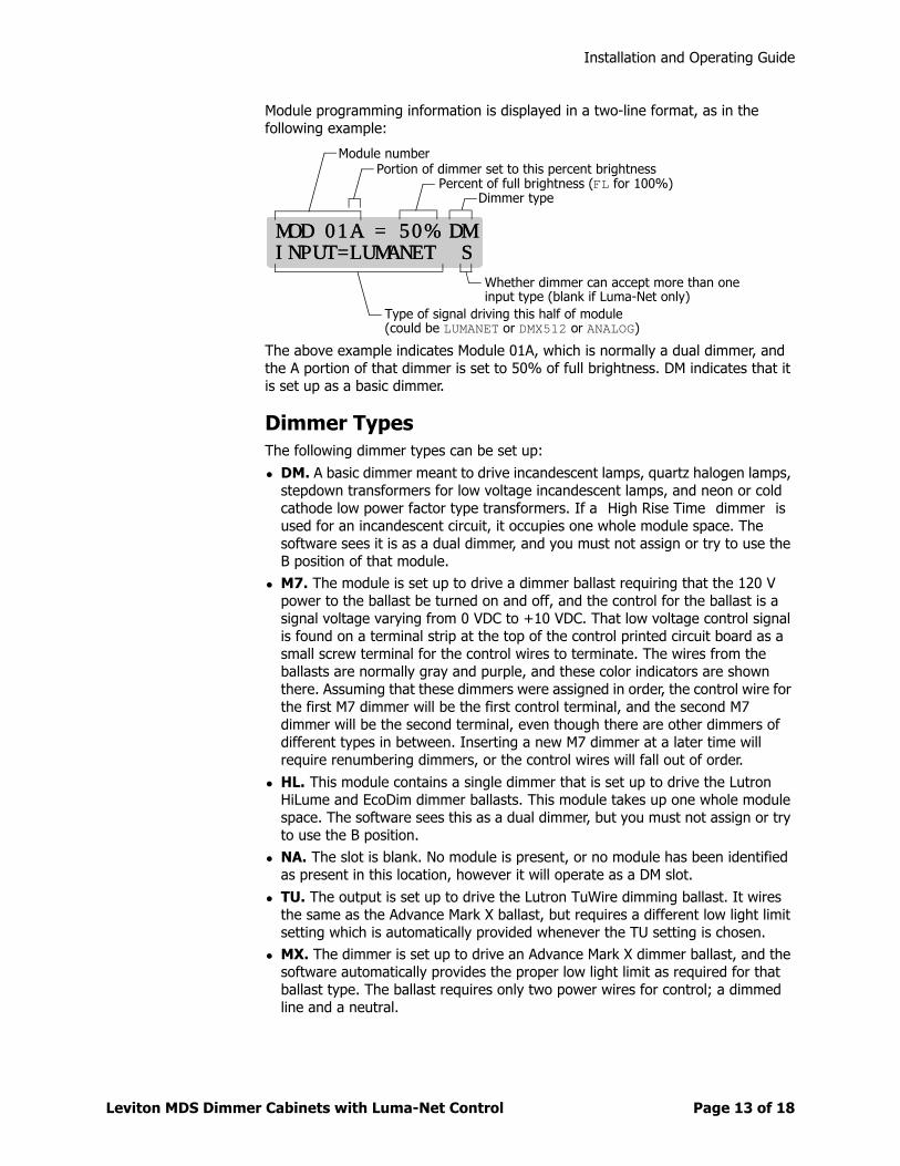
Module programming information is displayed in a two-line format, as in the following example:
The above example indicates Module 01A, which is normally a dual dimmer, and the A portion of that dimmer is set to 50% of full brightness. DM indicates that it is set up as a basic dimmer.
Dimmer TypesThe following dimmer types can be set up:
• DM. A basic dimmer meant to drive incandescent lamps, quartz halogen lamps, stepdown transformers for low voltage incandescent lamps, and neon or cold cathode low power factor type transformers. If a “High Rise Time” dimmer” is used for an incandescent circuit, it occupies one whole module space. The software sees it is as a dual dimmer, and you must not assign or try to use the B position of that module.
• M7. The module is set up to drive a dimmer ballast requiring that the 120 V power to the ballast be turned on and off, and the control for the ballast is a signal voltage varying from 0 VDC to +10 VDC. That low voltage control signal is found on a terminal strip at the top of the control printed circuit board as a small screw terminal for the control wires to terminate. The wires from the ballasts are normally gray and purple, and these color indicators are shown there. Assuming that these dimmers were assigned in order, the control wire for the first M7 dimmer will be the first control terminal, and the second M7 dimmer will be the second terminal, even though there are other dimmers of different types in between. Inserting a new M7 dimmer at a later time will require renumbering dimmers, or the control wires will fall out of order.
• HL. This module contains a single dimmer that is set up to drive the Lutron HiLume and EcoDim dimmer ballasts. This module takes up one whole module space. The software sees this as a dual dimmer, but you must not assign or try to use the B position.
• NA. The slot is blank. No module is present, or no module has been identified as present in this location, however it will operate as a DM slot.
• TU. The output is set up to drive the Lutron TuWire dimming ballast. It wires the same as the Advance Mark X ballast, but requires a different low light limit setting which is automatically provided whenever the TU setting is chosen.
• MX. The dimmer is set up to drive an Advance Mark X dimmer ballast, and the software automatically provides the proper low light limit as required for that ballast type. The ballast requires only two power wires for control; a dimmed line and a neutral.
MOD 01A = 50% DMMOD 01A = 50% DMINPUT=LUMANET SINPUT=LUMANET S
Module numberPortion of dimmer set to this percent brightness
Percent of full brightness (FL for 100%)Dimmer type
Whether dimmer can accept more than oneinput type (blank if Luma-Net only)
Type of signal driving this half of module(could be LUMANET or DMX512 or ANALOG)
Installation and Operating Guide
Leviton MDS Dimmer Cabinets with Luma-Net Control Page 14 of 1818
• ND. The module is set up for On/Off operation only. As the input signal approaches 40% the module switches full On. When the input falls below about 38% it switches Off. The slight difference in level is called hysteresis and is used to prevent chattering at the switching point.
• LV. A normal dimmer but with a low-end cutoff. This can be useful for certain load types such as driving a stepdown transformer for low voltage lights where a complete turnoff is needed at some low light level.
By pressing the UP button, you can step through each of the nine modules to determine how they are programmed, if they are receiving an input, and the source of that input. If a dimmer is being driven from two inputs (for example Luma-Net and DMS512), whichever input is higher has control, and that name appears.
This controller is capable of controlling up to 24 dimmers. In many of the MDS dimmer cabinets there are more than 24 dimmers, so you may find more than one controller electronic module. Each of these is capable of controlling another group of 24 dimmers. A cabinet containing 70 dimmers would require three of these electronic circuit cards providing a total of 72 available channels.
Changing a Module TypeChanging a module type involves the use of a password (setup code) to prevent unauthorized changes of vital data within the digital module. The factory default password is 0000.
If the password is lost or forgotten you will have to contact the factory to regain access to your system setup menus. If your system normally resides in a locked electrical room it may be best to keep the default password.
To access the module you want to change:
1 Press the UP button until Menu Setup appears on the LCD display.
2 Press the Select/Save button.Enter Setup Code 9999 appears on the LCD display.
3 Press the UP or DOWN buttons to change the 9999 to the actual password (setup code).Note: If it has not been changed use 0000.
4 Press the Select/Save button.The LCD display shows SETUP MENU SETUP MODULES?.
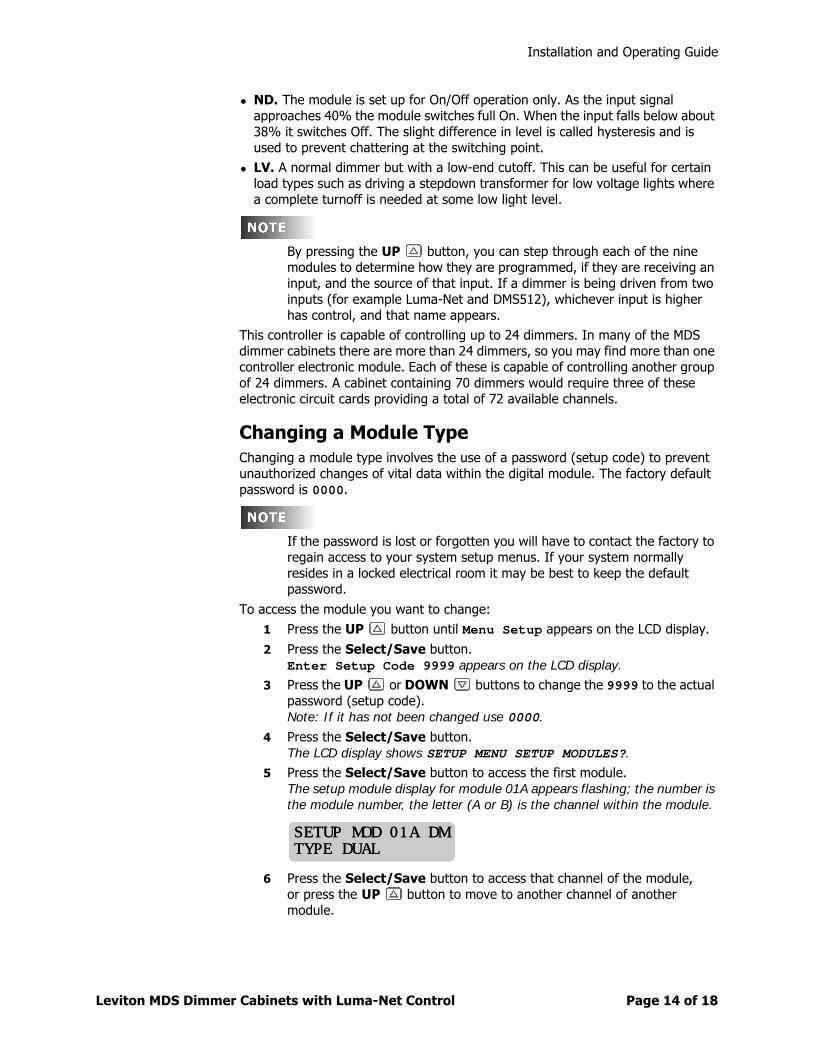
5 Press the Select/Save button to access the first module.The setup module display for module 01A appears flashing; the number is the module number, the letter (A or B) is the channel within the module.
6 Press the Select/Save button to access that channel of the module,or press the UP button to move to another channel of another module.
SETUP MOD 01A DMSETUP MOD 01A DMTYPE DUALTYPE DUAL
Installation and Operating Guide
Leviton MDS Dimmer Cabinets with Luma-Net Control Page 15 of 1818
Once you have reached the module you wish to change:
1 Press the Select/Save button.The number stops flashing, and the module type starts flashing.
2 With the type flashing, press the DOWN button until the LCD display shows Function = Dimmer.
3 Press the Select/Save button.Dimmer flashes.
4 Press the UP or DOWN buttons to scan through the functions.
5 Press the Select/Save button to select the desired function.The flashing moves from Function to several choices of dimmer types.
6 Press the UP or DOWN buttons to select a dimmer type
7 Press the Select/Save button.
8 Press the UP button to move on to another channel,or press the Cancel/Clear button three times slowly to return to the to- level menu.
Assigning Luma-Net and/or DMX512 ChannelsThe digital control board can assign dimming channels to various Luma-Net and/or DMX512 control channels within the software; no wiring changes are necessary.
Assigning Numbers AutomaticallyFor a simple configuration, the first control channel number is defined as a system-wide address (the factory default is 0001), and the system automatically assigns the control channel numbers in numerical order to the dimming zones (dimmers) within the dimmer cabinet. If a second dimmer cabinet is connected, its system-wide address can be set (to 0019, for example), and the dimming zones (dimmers) are assigned beginning with that number.
To change the system-wide addresses:
1 Press the UP button until the LCD display shows Menu Setup.
2 Press the Select/Save button.The LCD display shows Enter Setup Code = 9999.
3 Press the UP and DOWN buttons to change the 9999 to the actual setup code.The unit is unlocked so changes can be made.
4 Press the Select/Save button.The LCD display shows Setup Menu Setup Modules?.
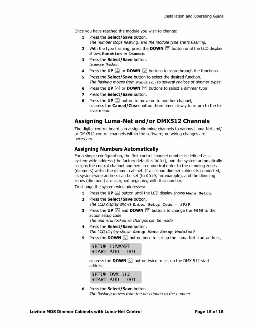
5 Press the DOWN button once to set up the Luma-Net start address,
or press the DOWN button twice to set up the DMX 512 start address.
6 Press the Select/Save button.The flashing moves from the description to the number.
SETUP LUMANETSETUP LUMANETSTART ADD = 001START ADD = 001
SETUP DMX 512SETUP DMX 512START ADD = 001START ADD = 001
Installation and Operating Guide
Leviton MDS Dimmer Cabinets with Luma-Net Control Page 16 of 1818
7 Press the UP and DOWN buttons to change the flashing number to the desired new address.
8 Press the Select/Save button to store the new address.The flashing returns to the description.
9 Press the Cancel/Clear button twice.You return to the top level menu.
Assigning Individual ChannelsYou might need to assign channels in a sequence other than the automatic assignment described above. This can happen when single rather than dual dimmers are installed, and you do not want to lose the continuity of the numbering system due to the loss of the second module channel. You might want to double up dimming channels on a given control channel. Or, it could be due to the requirements of multiple-room control stations.
After completing most of the assignments using the system-wide method described above, the individual dimming channels can be further modified using the LCD display.
To select a dimming channel to modify:
1 Press the UP button until the LCD display shows Menu Setup.
2 Press the Select/Save button.The LCD display shows Enter Setup Code = 9999.
3 Press the UP and DOWN buttons to change the 9999 to the actual setup code.
4 Press the Select/Save button.The LCD display shows Setup Menu Setup Modules?.
5 Press the Select/Save button.The LCD display shows Setup Mod 01A.
6 Press the UP and DOWN buttons to change the dimming channel to be modified (01A, 01B, 02A, etc.).
7 Press the Select/Save button to select the dimming channel.The flashing moves from the upper number to the lower description.
To modify the channel:
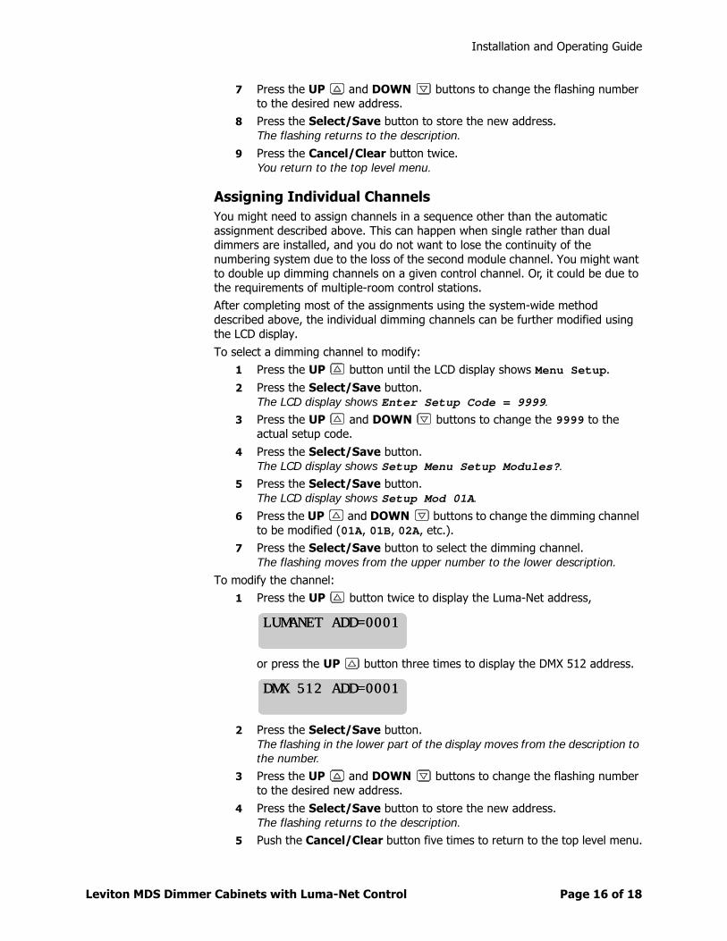
1 Press the UP button twice to display the Luma-Net address,
or press the UP button three times to display the DMX 512 address.
2 Press the Select/Save button.The flashing in the lower part of the display moves from the description to the number.
3 Press the UP and DOWN buttons to change the flashing number to the desired new address.
4 Press the Select/Save button to store the new address.The flashing returns to the description.
5 Push the Cancel/Clear button five times to return to the top level menu.
LUMANET ADD=0001LUMANET ADD=0001
DMX 512 ADD=0001DMX 512 ADD=0001
Installation and Operating Guide
Leviton MDS Dimmer Cabinets with Luma-Net Control Page 17 of 1818
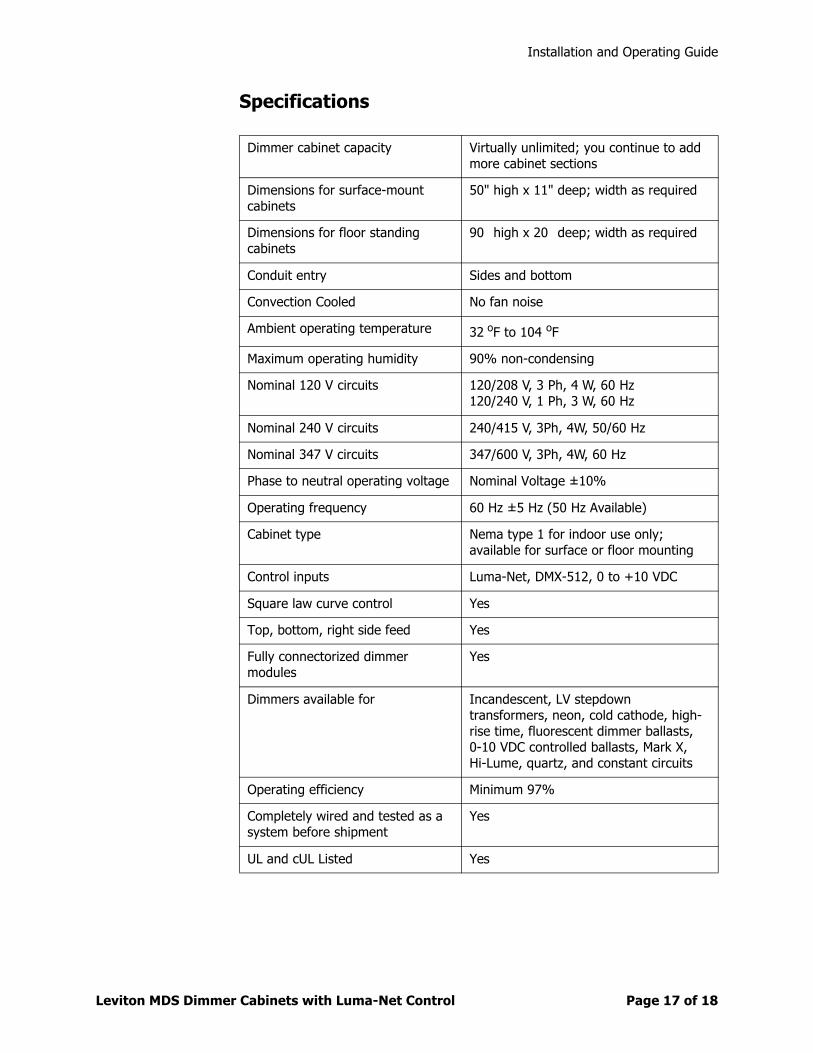
Specifications
Dimmer cabinet capacity Virtually unlimited; you continue to add more cabinet sections
Dimensions for surface-mount cabinets
50" high x 11" deep; width as required
Dimensions for floor standing cabinets
90” high x 20” deep; width as required
Conduit entry Sides and bottom
Convection Cooled No fan noise
Ambient operating temperature 32 oF to 104 oF
Maximum operating humidity 90% non-condensing
Nominal 120 V circuits 120/208 V, 3 Ph, 4 W, 60 Hz120/240 V, 1 Ph, 3 W, 60 Hz
Nominal 240 V circuits 240/415 V, 3Ph, 4W, 50/60 Hz
Nominal 347 V circuits 347/600 V, 3Ph, 4W, 60 Hz
Phase to neutral operating voltage Nominal Voltage ±10%
Operating frequency 60 Hz ±5 Hz (50 Hz Available)
Cabinet type Nema type 1 for indoor use only; available for surface or floor mounting
Control inputs Luma-Net, DMX-512, 0 to +10 VDC
Square law curve control Yes
Top, bottom, right side feed Yes
Fully connectorized dimmer modules
Yes
Dimmers available for Incandescent, LV stepdown transformers, neon, cold cathode, high-rise time, fluorescent dimmer ballasts, 0-10 VDC controlled ballasts, Mark X, Hi-Lume, quartz, and constant circuits
Operating efficiency Minimum 97%
Completely wired and tested as a system before shipment
Yes
UL and cUL Listed Yes
Installation and Operating Guide
Leviton MDS Dimmer Cabinets with Luma-Net Control Page 18 of 1818
Warranty Information
WarrantyLEVITON LIGHTING CONTROL DIVISION of Leviton Manufacturing Co Inc warrants its Dimmer Systems and Controls to be free of material and workmanship defects for a period of two years after system acceptance or 26 months after shipment, whichever comes first. This Warranty is limited to repair of replacement of defective equipment returned Freight Pre-Paid to Leviton Lighting Control Division at 20497 Teton Ave., Tualatin, Oregon 97062, USA. User shall call 1-800-959-6004 and request a return authorization number to mark on the outside of the returning carton, to assure that the returned material will be properly received at Leviton. All equipment shipped back to Leviton must be carefully and properly packed to avoid shipping damage. Replacements or repaired equipment will be returned to sender freight prepaid, F.O.B. factory. Leviton is not responsible for removing or replacing equipment on the job site, and will not honor charges for such work. Leviton will not be responsible for any loss of use time or subsequent damages should any of the equipment fail during the warranty period, but agrees only to repair or replace defective equipment returned to its plant in Tualatin, Oregon. This Warranty is void on any product that has been improperly installed, overloaded, short circuited, abused, or altered in any manner. Neither the seller nor Leviton shall be liable for any injury, loss or damage, direct or consequential arising out of the use of or inability to use the equipment. This Warranty does not cover lamps, ballasts, and other equipment which is supplied or warranted directly to the user by their manufacturer. Leviton makes no warranty as to the Fitness for Purpose or other implied Warranties.