installation and detail specification - … · 25-010_c.doc 2-26-2015 installation and detail...
TRANSCRIPT

25-010_C.DOC 2-26-2015
INSTALLATION AND DETAIL SPECIFICATION
FOR THE
EX-3 SILVER HAWKTM
SERVO KITS
EX-3VA2TM Multiport Fuel Injection
EX-3VS2TM Single-Point Fuel Injection

25-010_C.DOC i
Precision Airmotive LLC fuel systems are produced using the highest quality materials and components. This gives the user the assurance that they have been manufactured and tested under the strictest quality standards in the industry.
We take great pride in the reputation our products and services have earned through years of performing safely and dependably under all flying conditions.
The Silver HawkTM EX, non-certified fuel injection system is proven technology drawn from decades of fuel metering engineering by Precision Airmotive. Manufactured as experimental, this new Patent Pending Silver HawkTM EX kit provides experimental aircraft with precise, dependable, and reliable fuel metering.
Only Precision Airmotive supplies the latest training manuals, technical, and engineering support.
If you have any questions, please call our product support department at 360-651-8282, or visit our website: http://precisionairmotive.com
Thank you for choosing a Precision Airmotive LLC product.
WARNING:
The use of unauthorized parts in any system can cause product malfunctions, which could result in damage to, or destruction of, equipment and injury to and/or death of personnel. Use only Precision Airmotive replacement parts as specified in the Illustrated Parts List.
PERMISSION TO REPRINT
PERMISSION TO REPRINT THIS “INSTALLATION AND DETAIL SPECIFICATIONS FOR THE EX-3 SILVER HAWKTM SERVO KITS” DOCUMENT IS GRANTED, SO LONG AS CONTENT OF INFORMATION REMAINS INTACT AND APPROPRIATE CREDIT IS GIVEN.
http://precisionairmotive.com
14800 40th Avenue NE, Marysville, WA 98271 Telephone (360) 651-8282, Fax (360) 651-8080

25-010_C.DOC ii
TABLE OF CONTENTS
1. Purpose .............................................................................................................. 1
2. Description ......................................................................................................... 1
3. General Specifications for EX-3VA2TM and EX-3VS2TM
3.1. Specifications for Both Models ..................................................................... 1
3.2. Specifics for EX-3VA2TM .............................................................................. 2
3.3. Specifics for EX-3VS2TM ............................................................................... 2
4. Installation Requirements ................................................................................ 2-3
5. Environmental Requirements .......................................................................... 3
6. Configuration Adjustment
6.1. Throttle and Mixture Control Levers .......................................................... 3
6.2. Fuel Inlet and Alternate Inlet Fittings ......................................................... 3-4
6.3. Servo Fuel Outlet and Alternate Outlet Fittings ........................................ 4
7. Starting Procedure ............................................................................................ 4
8. Idle Speed and Idle Fuel Flow .......................................................................... 4
9. Economy Cruise Using Mixture Control Lever ............................................. 4
10. Fuel Flow Adjustment Using the Mixture Adjustment Needle ..................... 5
11. Accelerator Pump ............................................................................................. 6
12. Fuel Leaks .......................................................................................................... 6
13. Maintenance, Repair, and Overhaul ............................................................... 6
14. Drawing ............................................................................................................ 6
Fuel System Layout ....................................................................................... 7
Nozzle ............................................................................................................. 8
Flow Divider .................................................................................................. 9
EX-3VA2TM Servo ......................................................................................... 10
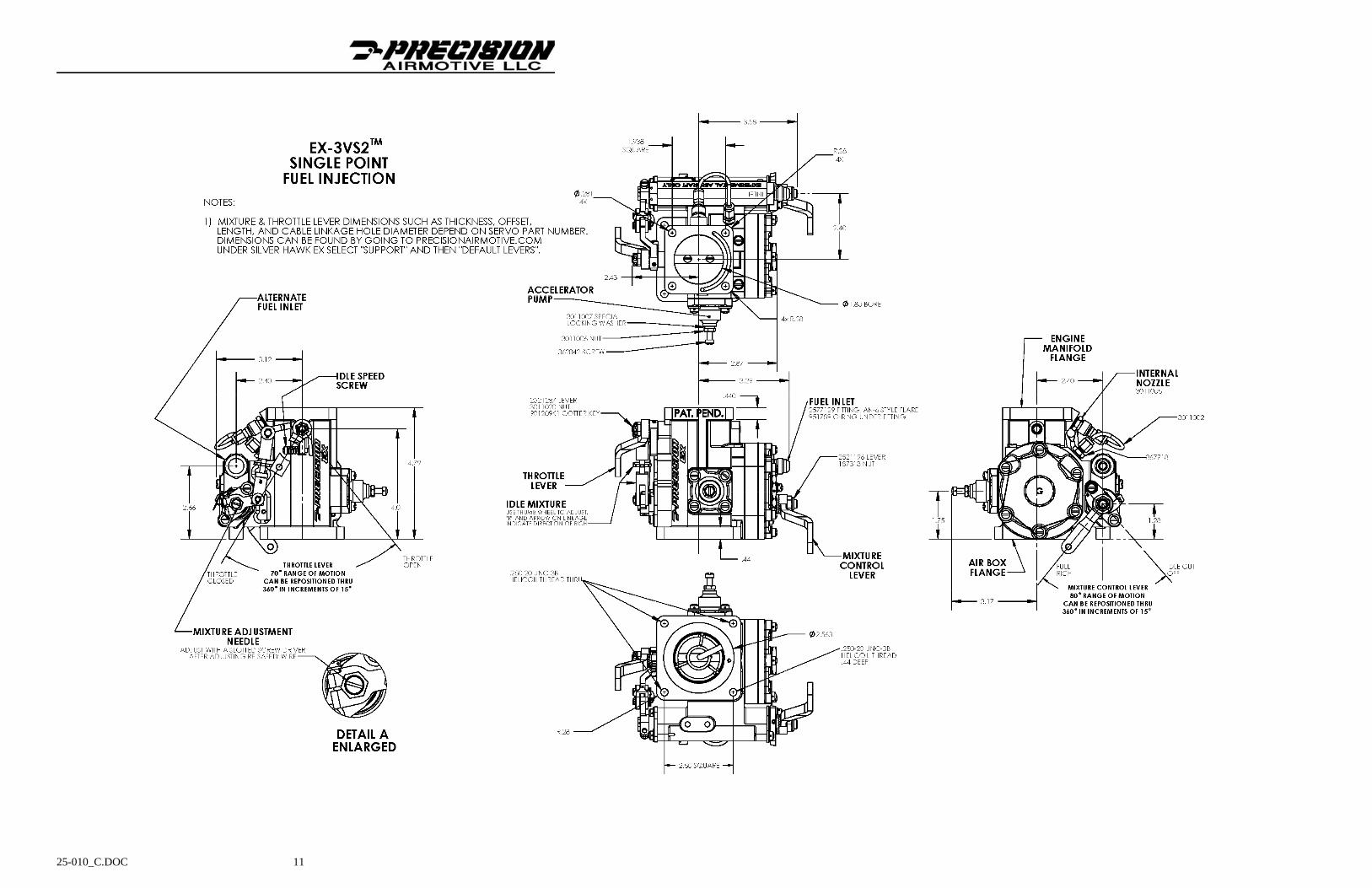
EX-3VS2TM Servo .......................................................................................... 11
15. Torque Specifications ....................................................................................... 12
16. Troubleshooting Tables .................................................................................... 13-14
17. Troubleshooting Run Up Sheet ........................................................................ 15
Appendixes
Appendix A: Starting Procedure ........................................................................ 16
Appendix B: Idle Speed & Mixture Adjustments ............................................. 17-19 for Fuel Injection Systems
25-010_C.DOC 1
1.0 Purpose. This specification provides a description of the EX-3VA2TM and EX-3VS2TM mechanical fuel injection servo kits and the applications where they can be used. It also outlines the requirements for new installations.
2.0 Description. The multiport fuel injection system kit consists of an EX-3VA2 TM servo, flow divider, and nozzles. The single-point fuel injection system kit has only one component the EX-3VS2 TM.
2.1 Both EX-3 mechanical fuel injection servos are based on the principle of measuring airflow to establish correct fuel flow. A venturi is used to measure the airflow and create an air force proportional to airflow. An in-line diaphragm type regulator is used to convert an air force into a fuel force. The fuel force is applied across a fuel metering section and makes fuel flow proportional to airflow. The servo is the primary component used in the fuel injection system and performs all functions required to establish fuel flow volumes.
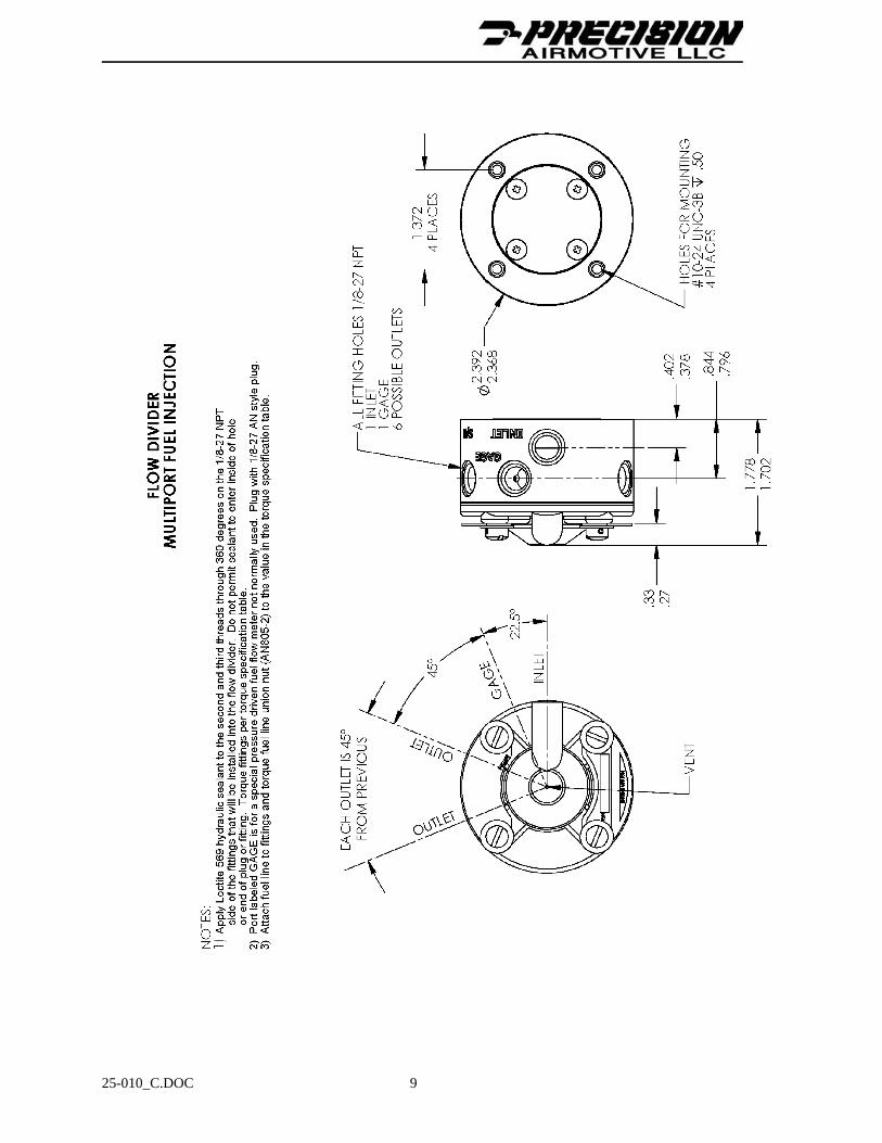
2.2 The multiport fuel injection kit uses a flow divider, which is used to distribute the metered fuel flow from the servo to the nozzles. The flow divider controls how much fuel goes to each nozzle from idle to about 25% horsepower. Above this power, the fuel distribution is managed by the nozzles. The single-point fuel injection system does not use a flow divider because all the fuel is delivered to one nozzle which is located downstream of the EX-3VS2 servo’s throttle valve.
2.3 The single-point fuel injection system only has one fuel nozzle as mentioned before. The multiport fuel injection system has a fuel nozzle installed into each one of the engine’s cylinder intake runners for equal cylinder-to-cylinder fuel distribution. The nozzles incorporate an air bleed hole that is vented to atmospheric air. This hole is used to emulsify and atomize the fuel as it enters into the air intake stream.
3.0 General Specifications for EX-3VA2TM and EX-3VS2TM
3.1 Specifications for Both Models
3.1.1 Designed for engines that make roughly 100-150 horsepower.
3.1.2 Can be adapted to work on both turbo and non-turbo engines.
3.1.3 Will mount on Lycoming O-235 and Continental (TCM) O-200 and O-240 engines. Servos can be installed on engines other than Lycoming and Continental with customer supplied intake manifold adapters. The installation drawings in this manual show the bore size and bolt patterns for the air box and manifold sides of the servo.
3.1.4 Idle speed and mixture are adjustable for smooth idle.
3.1.5 An external mixture needle is used to adjust the fuel flow through the main jet. This allows rated horsepower fuel flow to be fine-tuned.
3.1.6 A mixture control lever is used for leaning during cruise or during high altitude operation.
3.1.7 Shares many of the same features as the MA-3SPA Marvel Schebler Carburetors such as a 1.800” throttle bore and the installation bolt patterns for the air box and manifold. The EX-3VA2TM is also the same height; the EX-3VS2TM is .500” taller.
3.1.8 No throttle fly or venturi carburetor icing. Fuel is NOT sprayed in these areas but after the throttle fly on the EX-3VS2TM or into the intake manifold ports if using the EX-3VA2TM.
3.1.9 Fully aerobatic capable without any modifications. However, fuel pressure to the servo must be maintained.
25-010_C.DOC 2
3.2 Specifics for EX-3VA2TM
3.2.1 A multiport mechanical fuel injection system consisting of three primary components: EX-3VA2TM throttle body servo, flow divider, and fuel nozzles.
3.2.2 Fuel is sprayed into each cylinder’s intake port by means of fuel nozzles. This gives each cylinder the same amount of fuel.
3.2.3 Approximate combined weight for the servo, flow divider, and four nozzles is 4.76 pounds.
3.3 Specifics for EX-3VS2TM
3.3.1 Single-point mechanical fuel injection system sometimes called throttle body fuel injection. The EX-3VS2TM throttle body servo is the only main component of the system.
3.3.2 Fuel is sprayed just after the throttle valve into the intake sump or manifold by means of a fuel nozzle that is part of the throttle body.
3.3.3 The servo has a built in accelerator pump. This feature ensures smooth engine operation when the throttle is opened. It is needed since the fuel nozzle is not near the intake valve of the engine.
3.3.4 Approximate servo weight is 4.13 pounds.
4.0 Installation Requirements
Dimensional: See installations drawings for representational information. Other configurations are available for the selection and orientation of fuel fittings and control levers. Contact Precision Airmotive Product Support for specifics.
Servo Fuel Inlet Fitting: Flared AN#6 (9/16-18)
Servo Fuel Outlet Fitting for EX-3VA2TM: Flared AN #4 (7/16-20)
Fuel Pressure: Nominal: 20-50 psig relative to airbox or upper deck pressure
Minimum Operating: The minimum operating pressure shall be determined by installation specific testing.
Max Operating: 80 psia max
Max Momentary Peak: 140 psia max
Fuel Filtration: The fuel supplied to the servo shall be filtered to 32 micron nominal. This filtration may occur prior to the engine driven pump, but all other pumps and valves shall be upstream of the filter.
Fuel Inlet & Outlet Lines: There are several options for fuel lines. They can be acquired from aircraft component suppliers. The fuel line should be designed for fuel, rated at 300°F or higher, and must be fire sleeved (or have an integral fire sleeve) and be able to handle 1000 psi. Only the multiport EX-3VA2TM requires an outlet fuel line.
Flow Divider: A list of available fittings and nozzle fuel lines can be found at http://www.precisionairmotive.com

25-010_C.DOC 3
Fuel Temp: 120°F recommended max at inlet to servo to minimize vapor formation downstream of the servo. Fuel temperatures upstream of the servo must be low enough to prevent vapor formation in the fuel lines. It is assumed that temperatures may exceed the above listed temperatures under some conditions, but these temperatures may result in degraded performance at low engine speeds.
Inlet Air Temp: The induction air temperature measured at the inlet to the servo shall not exceed 400°F.
Inlet Air Filter: The air inlet to the servo needs to be filtered, contact the airplane kit supplier for the appropriate filter. An alternate air door must be part of the air inlet design. It is needed if the air filter gets plugged by icing or by some other means.
Orientation: The servo may be installed in any orientation.
5.0 Environmental Requirements
Operating Temperature: -65°F to 300°F
This temperature shall be measured on the exterior of the throttle body adjacent to the outlet port on the valve body side of the servo.
6.0 Configuration Adjustment. Details on what can be changed regarding the fuel inlet and outlet fittings and the throttle and mixture levers are mentioned. See the installation drawings in this manual for the locations of where these components exist on the servo.
6.1 Throttle and Mixture Control Levers
6.1.1 The levers can be removed and rotated to different angles to accommodate the aircraft needs. The levers can even be swapped.
6.1.2 The throttle lever is held on with a castellated nut P/N 3011020 and cotter pin P/N 901209K1. Whenever the throttle lever is moved or changed the nut must be torqued properly and a new cotter pin used. See torque specification table for the torque values.
6.1.3 The mixture control lever is held on with an elastic stop nut P/N 187313. If the mixture lever is moved or changed a new nut must be installed and torqued to the value noted in the torque specification table.
6.2 Fuel Inlet and Alternate Inlet Fittings
6.2.1 The servo has two possible fuel inlet ports. One of the ports will have a flared AN #6 type fuel fitting installed. This port is called the “Inlet”. The other port is called “Alternate Inlet” and it is plugged with a fitting and safety wired to the servo body.

25-010_C.DOC 4
6.2.2 The inlet and alternate inlet fittings can be swapped or changed, but it must be done correctly to ensure flight safety. There is a fuel filter inside of the servo. Both of the fittings are specially designed to work together to hold the filter in the proper orientation. Only use Precision Airmotive LLC parts; using any other parts including standard AN parts can damage the filter or servo body causing loss of fuel flow and a flight safety problem. The part numbers for these are called out on the drawings. The following procedure defines how to properly swap fitting locations or change fittings.
6.2.2.1 Remove the inlet fitting first, then the fuel filter, and finally the alternate inlet plug. If the plug is removed first, particles may come out of the fuel filter and contaminate the inside of the servo!
6.2.2.2 Inspect the o-rings on all three of the components to ensure that they are not nicked, cracked, or damaged and replace them if they are. Lubricate the three o-rings, the inlet and alternate ports in the servo body, and the inside of the fuel inlet fitting with clean engine oil.
6.2.2.3 Install the plug into the new location and torque to the value noted in the torque specification table. Safety wire the plug to the servo body ensuring that the safety wire pulls in the direction to tighten the plug.
6.2.2.4 Insert the filter into the fuel inlet port starting with the spring end first. The filter will slide in until the spring touches the plug.
6.2.2.5 Install the inlet fitting into its new location and torque to the value in the torque specification table.
6.3 Servo Fuel Outlet
6.3.1 The single-point fuel injection servo EX-3VS2TM has an outlet port that feeds a single nozzle that is installed downstream of the throttle valve in the servo. The location of the nozzle and the stainless steel fuel line that attaches to it cannot be adjusted.
6.3.2 The multiport fuel injection servo EX-3VA2TM has an outlet port with a #4 AN flared fitting installed in it. The supplied fitting may be straight or angled depending on the kit purchased. This fitting can be rotated or changed if necessary. Prior to installing a fitting inspect the o-ring for nicks, cracks, or other damage and replace it if it does. Part numbers may be found on the drawings. Lubricate the o-ring, fitting, and the port with clean engine oil then install the fitting and torque to the value found in the torque specification table.
7.0 Starting Procedure. Steps on how to start the engine are located in Appendix A.
8.0 Idle Speed and Idle Fuel Flow. Steps on how to adjust idle speed and fuel flow are described in the Appendix.
9.0 Economy Cruise Using Mixture Control Lever. The EX-3 servo comes with a standard mixture control lever that is operated in the cockpit via linkage. It is used for leaning the fuel flow out during cruise (less than 75% engine power). How to properly lean out the engine during cruise is defined by the airframe and engine manufacturer.

25-010_C.DOC 5
10.0 Fuel Flow Adjustment Using the Mixture Adjustment Needle
10.1 The required fuel flow (FF) at rated horsepower (HP) is defined by the engine and airframe manufacturers. Usually the FF creates an air/fuel ratio richer than best power in the range of 75-100% HP when the mixture lever in the full rich position. This is to promote cylinder cooling and avoid detonation. The EX-3 servo is shipped so that the FF falls within these manufacturer’s requirements. Engine life, performance, and economy can be dramatically affected by the FF. How well the engine is running is directly related to safety of flight. Precision Airmotive LLC’s Web Site has information and various links for assisting the aircraft operator in the determining if the engine is too rich or lean with the mixture lever in the full rich position.
10.2 If the rated RPM fuel flow is too lean or rich with the mixture control in the full rich position for the engine or airframe manufacturer then the mixture adjustment needle (sometimes called a tweeker) can be rotated. The location of this needle is shown in the drawings found in this document. Turning the needle in reduces the FF through the main jet in the servo and turning the needle out does the opposite. Adjusting the needle not only changes the FF at rated HP but everywhere else but to a lesser extent.
10.3 To make adjustment to the mixture needle do the following:
10.3.1 Cut the safety wire that is covering the needle.
10.3.2 Determine the current position of the needle by screwing it in and counting the number of turns (clockwise when facing it) it takes to gently bottom out. Record this value for future use. Unscrew the needle (counterclockwise when facing it) back to its original location. Never unscrew the head of the needle beyond the safety wire holes to avoid a fuel leak.
10.3.3 To reduce the FF, turn the needle inward (clockwise when facing it). Each turn of the needle can affect the FF by several lbs/hr.
10.3.4 To increase the FF, turn the needle out (counterclockwise when facing it). Each turn of the needle can affect the FF by several lbs/hr.
10.3.5 Install new safety wire over the top of the needle. This step is for safety and must not be forgotten.

25-010_C.DOC 6
11.0 Accelerator Pump
11.1 Only the EX-3SV2TM single-point fuel injection servo has an accelerator pump. When the throttle is opened quickly, the accelerator pump delivers extra fuel to the engine so the engine responds quickly and does not have a lean stumble. The accelerator pump has been adjusted to a position, which has proven to work well. The location of the accelerator pump is shown on the EX-3VS2TM drawing.
11.2 If the accelerator pump needs to be adjusted then perform the following steps:
11.2.1 Loosen the nut in the center of the accelerator cover.
11.2.2 The screw that goes through the nut is what adjusts the fuel flow. Determine the current screw position by turning it in and counting the number of turns (clockwise when facing it) it takes to gently bottom out. Record this value for future use. The normal position that the screw generally will be is 2 turns out. Never exceed 6 turns out; to ensure there is enough thread engagement. Turn the screw (counterclockwise when facing it) to its original location.
11.2.3 To reduce the FF, turn the screw inward (clockwise when facing it). A quarter turn may be all that is needed.
11.2.4 To increase the FF, turn the needle out (counterclockwise when facing it). A quarter turn may be all that is needed.
11.2.5 After adjusting the screw, tighten the nut to the torque found on the torque table. There is a special locking washer under the nut. Attempt to unscrew the nut using the same torque that was used to tight the nut. If the nut does not break loose, retorque the nut. If the nut does break loose, replace the nut and locking washer with new parts.
12.0 Fuel Leaks. Whenever a fuel line, fuel fitting, or the mixture adjustment needle is changed or moved always check to ensure the fuel lines are tight and that there are no fuel leaks. A slight stain by the fuel nozzles is not unusual.
13.0 Maintenance, Repairs, and Overhauls. Overhauls can only be done by Precision Airmotive. Some minor repairs can be done by the customer but Precision Airmotive should be contacted first to get approval and guidance. Maintenance and overhaul requirements for the servo, flow divider, and nozzles are:
13.1 The time between overhaul (TBO) is the same as the TBO specified by the engine manufacturer for the engine on which the fuel system was installed (up to a maximum of 2600 hours) or ten (10) years since the system was placed in service or last overhauled, whichever occurs first.
13.2 The servo’s internal fuel filter is a last chance filter. This filter does not need to be checked or cleaned unless it is suspected that contaminates have entered the fuel line after the aircraft’s fuel filter. The “Installation Requirements” section of this manual states what is required for aircraft filtration.
14.0 Drawings. Included are the drawings for fuel system layouts, EX-3 servos, flow divider, and nozzles.

25-010_C.DOC 7

25-010_C.DOC 8
25-010_C.DOC 9

25-010_C.DOC 10
25-010_C.DOC 11

25-010_C.DOC 12
Section 15 Torque Specifications
Servo
Object Installation Torque
Fuel Inlet Fitting Into Servo 65-70 in-lbs
Alternate Fuel Inlet Fitting Into Servo 65-70 in-lbs
Fuel Outlet Fitting Into Servo 45-50 in-lbs
Alternate Fuel Outlet Fitting Into Servo 45-50 in-lbs
Mixture Control Lever Elastic Nut
On Servo 90-100 in-lbs
Throttle Lever Nut On Servo See Below
Torque throttle lever nut to 50 in-lbs and tighten further as required to install cotter pin. If alignment cannot be accomplished without exceeding 70 in-lbs, back off half a turn, then retighten. Occasionally it may be necessary to select a new part. Once the pin is inserted, bend the ends over.
Flow DividerObject Installation Torque
Fuel Inlet Fitting Into Flow Divider 45-65 in-lbs
Outlet Fittings Into Flow Divider 45-65 in-lbs
Gage Port Fitting Into Flow Divider 45-65 in-lbs
Outlet Fuel Lines From Outlet Fittings to Nozzles 25-50 in-lbs, do NOT exceed 50 in-lbs
Mounting Bracket On Bottom of Flow Divider 20-30 in-lbs
Nozzles
Object Installation Torque
Nozzle Into Cylinder Head or Servo 60 in-lbs
Fuel Lines Between Flow Divider and Nozzles 25-50 in-lbs, do NOT exceed 50 in-lbs
Accelerator Pump
Object Installation Torque
Jam Nut On Servo’s Accelerator Cover 20-25 in-lbs

25-010_C.DOC 13
Section 16 Troubleshooting Tables
INSTALLATION: It is absolutely necessary to install servo, flow divider, and nozzles per the engine and/or airframe manual for proper operation. Failure to do so may result in unsatisfactory operation, injury, or death.
REMOVAL: Before removing fuel injection components from engine for warranty consideration, and after verifying all other components work properly, troubleshoot the following symptoms:
PROBLEM PROBABLE CAUSE REMEDY
HIGH FUEL FLOW READING
PLUGGED NOZZLE IF HIGH FUEL FLOW IS ACCOMPANIED BY LOSS OF POWER, AND ROUGHNESS.
REMOVE AND CLEAN NOZZLES. A 20 MINUTE SOAK IN HOPPES #9 GUN CLEANING SOLVENT, A STODDARD SOLVENT RINSE AND BLOW DRY. CHECK SYSTEM FOR SOURCE OF CONTAMINATION.
FAULTY GAGE. CRISS-CROSS GAGES AND REPLACE IF NECESSARY. IF SINGLE ENGINE, REPLACE GAGE.
STAGGERED MIXTURE CONTROL LEVERS
IF TAKEOFF IS SATISFACTORY, DO NOT BE TOO CONCERNED ABOUT STAGGERED LEVERS BECAUSE SOME MISALIGNMENT IS NORMAL WITH TWIN ENGINE INSTALLATION.
CHECK RIGGING.
POOR CUT-OFF IMPROPER RIGGING OF AIRCRAFT LINKAGE TO MIXTURE CONTROL.
ADJUST.
ROUGH ENGINE (TURBO CHARGED) AND POOR CUT-OFF
NOZZLE AIR BLEED HOLE (S) CLOGGED.
CLEAN OR REPLACE NOZZLES.
ENGINE WILL NOT ACCELERATE PAST A GIVEN RPM
OIL IN AIR CHAMBER. REFER TO PRECISION AIRMOTIVE SERVICE INFORMATION LETTER RS-40
ROUGH IDLE SLIGHT AIR LEAKS INTO INDUCTION SYSTEM THROUGH LOOSE INTAKE PIPES OR DAMAGED “O” RINGS. USUALLY ABLE TO ADJUST INITIAL IDLE BUT ROUGH IN 1,000-1,500 RPM RANGE.
REPAIR AS NECESSARY
LARGE AIR LEAKS INTO INDUCTION SYSTEM SUCH AS MISSING PIPE PLUGS, ETC. USUALLY UNABLE TO THROTTLE ENGINE DOWN BELOW 800-900 RPM.
REPAIR AS NECESSARY
FUEL VAPORIZING IN FUEL LINES OR DISTRIBUTOR. ENCOUNTERED ONLY UNDER HIGH AMBIENT TEMPERATURE CONDITIONS OR FOLLOWING PROLONGED OPERATION AT LOW IDLE RPM’S.
KEEP TEMPERATURES LOW BY:
- AVOID EXCESSIVE GROUND RUN. - RPM’S AS HIGH AS PRACTICAL. - COWL FLAPS OPEN WHEN PRACTICAL UPON RESTARTING HOT ENGINE, OPERATE AT 1,200-1,500 RPM FOR SEVERAL MINUTES TO REDUCE RESIDUAL HEAT IN ENGINE COMPARTMENT.
25-010_C.DOC 14
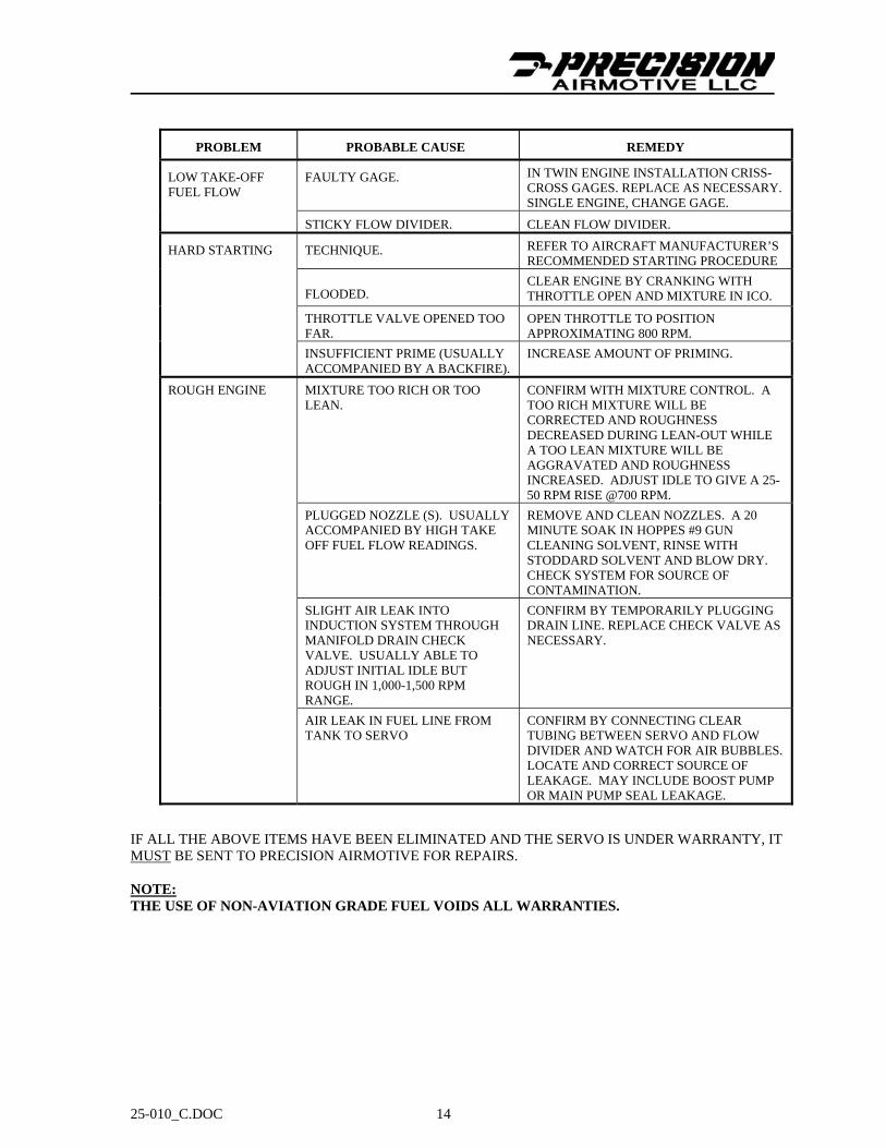
PROBLEM PROBABLE CAUSE REMEDY
LOW TAKE-OFF FUEL FLOW
FAULTY GAGE. IN TWIN ENGINE INSTALLATION CRISS-CROSS GAGES. REPLACE AS NECESSARY. SINGLE ENGINE, CHANGE GAGE.
STICKY FLOW DIVIDER. CLEAN FLOW DIVIDER.
HARD STARTING TECHNIQUE. REFER TO AIRCRAFT MANUFACTURER’S RECOMMENDED STARTING PROCEDURE
FLOODED.
CLEAR ENGINE BY CRANKING WITH THROTTLE OPEN AND MIXTURE IN ICO.
THROTTLE VALVE OPENED TOO FAR.
OPEN THROTTLE TO POSITION APPROXIMATING 800 RPM.
INSUFFICIENT PRIME (USUALLY ACCOMPANIED BY A BACKFIRE).
INCREASE AMOUNT OF PRIMING.
ROUGH ENGINE MIXTURE TOO RICH OR TOO LEAN.
CONFIRM WITH MIXTURE CONTROL. A TOO RICH MIXTURE WILL BE CORRECTED AND ROUGHNESS DECREASED DURING LEAN-OUT WHILE A TOO LEAN MIXTURE WILL BE AGGRAVATED AND ROUGHNESS INCREASED. ADJUST IDLE TO GIVE A 25-50 RPM RISE @700 RPM.
PLUGGED NOZZLE (S). USUALLY ACCOMPANIED BY HIGH TAKE OFF FUEL FLOW READINGS.
REMOVE AND CLEAN NOZZLES. A 20 MINUTE SOAK IN HOPPES #9 GUN CLEANING SOLVENT, RINSE WITH STODDARD SOLVENT AND BLOW DRY. CHECK SYSTEM FOR SOURCE OF CONTAMINATION.
SLIGHT AIR LEAK INTO INDUCTION SYSTEM THROUGH MANIFOLD DRAIN CHECK VALVE. USUALLY ABLE TO ADJUST INITIAL IDLE BUT ROUGH IN 1,000-1,500 RPM RANGE.
CONFIRM BY TEMPORARILY PLUGGING DRAIN LINE. REPLACE CHECK VALVE AS NECESSARY.
AIR LEAK IN FUEL LINE FROM TANK TO SERVO
CONFIRM BY CONNECTING CLEAR TUBING BETWEEN SERVO AND FLOW DIVIDER AND WATCH FOR AIR BUBBLES. LOCATE AND CORRECT SOURCE OF LEAKAGE. MAY INCLUDE BOOST PUMP OR MAIN PUMP SEAL LEAKAGE.
IF ALL THE ABOVE ITEMS HAVE BEEN ELIMINATED AND THE SERVO IS UNDER WARRANTY, IT MUST BE SENT TO PRECISION AIRMOTIVE FOR REPAIRS. NOTE: THE USE OF NON-AVIATION GRADE FUEL VOIDS ALL WARRANTIES.
25-010_C.DOC 15
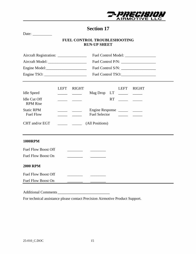
Section 17 Date: __________
FUEL CONTROL TROUBLESHOOTING RUN-UP SHEET
Aircraft Registration: _______________ Fuel Control Model: ________________
Aircraft Model: ____________________ Fuel Control P/N: __________________
Engine Model: _____________________ Fuel Control S/N: __________________
Engine TSO: ______________________ Fuel Control TSO:__________________ LEFT RIGHT LEFT RIGHT Idle Speed _____ _____ Mag Drop LT _____ _____
Idle Cut Off _____ _____ RT _____ _____ RPM Rise
Static RPM _____ _____ Engine Response _____ _____ Fuel Flow _____ _____ Fuel Selector _____ _____ CHT and/or EGT _____ _____ (All Positions)
1000RPM
Fuel Flow Boost Off ________ ________
Fuel Flow Boost On ________ ________
2000 RPM
Fuel Flow Boost Off ________ ________
Fuel Flow Boost On ________ ________
Additional Comments ___________________________
For technical assistance please contact Precision Airmotive Product Support.

25-010_C.DOC 16
APPENDIX A
Starting Procedures
The following starting procedures has been proven successful; however, if there is conflict, information given in the Aircraft Operation Manual should be followed.
1. Cold Starts
1.1. Place mixture control in idle cut-off position.
1.2. Set throttle to 1/8 open position.
1.3. Master switch –ON-.
1.4. Boost pump switch –ON-.
1.5. Move mixture control to FULL-RICH until fuel flow indicator reads 2 to 4 GPH then immediately return mixture control to cut-off position.
NOTE
On installations where a fuel flow indicator is not used allow 4 to 5 seconds in place of
reading 2 to 4 GPH on the gage.
1.6. Engage start - - when engine starts move mixture control to full rich position.
2. Warm Starts
Use the same procedure as for cold starts except the boost pump may be left “off” and step 1.5 eliminated. DO NOT PRIME.
25-010_C.DOC 17
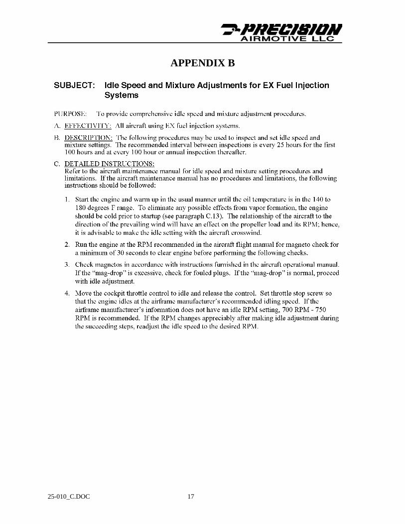
APPENDIX B
25-010_C.DOC 18

25-010_C.DOC 19