superseding 16 february 1996 detail specification
TRANSCRIPT

INCH-POUNDMIL-DTL-11891G(AT)25 February 1998SUPERSEDINGMIL-PRF-11891F(AT)16 February 1996
DETAIL SPECIFICATION
TRACK SHOE SETS, TRACK SHOE ASSEMBLIES, TRACK SHOEPADS AND TRACK SHOE BUSHINGS, VEHICULAR: ELASTOMERIZED
This specification is approved for use by U.S. Army Tank-automotive and ArmamentsCommand, Department of the Army, and is available for use by all Departments andAgencies of the Department of Defense.
1. SCOPE
1.1 Scope. This specification identifies the requirements for qualification and productioncontrol of track systems supporting U.S. Military Tracked Vehicles. This specification is intendedprimarily for the qualification of elastomeric compounds used in the fabrication of track and trackcomponents and to ensure that the quality and performance established at qualification ismaintained throughout production. The contractor is held fully responsible for the entireassembly/component including all non-elastomeric components and fasteners. The qualifiedproducts list (QPL) is divided by individual track components (pads, bushings and roadwheelpath/shoe body) listing the contractors qualified to produce the various components, thecontractor’s address, and compound identification. The QPL also identifies contractors qualifiedto assemble the various track components into full assemblies/systems. This includes bushinginsertion, pad installation and connecting component (end connectors, center guides) assembly. The track shoe assemblies may be acquired either as sets, assemblies or as individual components(pin bushing assemblies or pads) as specified by the acquiring activity (see 6.1).
Beneficial comments (recommendations, additions, deletions) and any pertinent data which maybe of use in improving this document should be addressed to: U.S. Army Tank-automotive andArmaments Command, ATTN: AMSTA-TR-E/BLUE, Warren, MI 48397-5000, by using theStandardization Document Improvement Proposal (DD Form 1426) appearing at the end of thisdocument, or by letter.AMSC N/A FSC 2530DISTRIBUTION STATEMENT A. Approved for public release; distribution is unlimited.
Downloaded from http://www.everyspec.com

MIL-DTL-11891G(AT)
2
1.2 Classification. The track shoe assemblies or components to be procured inaccordance with this specification are of the following types and styles:
Type I.................................Single-pin track shoeStyle A....................................Integral padStyle B....................................Replaceable pad
Type II................................Double-pin track shoeStyle A.................................Integral padStyle B..................................Replaceable pad
Type III.................................Bushing assemblies
1.3 Track systems. Applicable track systems are as follows:
Designation Type / style TDP no.T142 (see note 1) II / B 11645125T107 I / A 8705914T154 II / B 12268550T136 II / B 10954051T130E1 I / B 11677988T138 I / A 10948405T132E1 I / B 10934639T144 II / A 10892811T164 I / B 12352500T150 II / B 12306600T157I I / B 12359466
NOTE: The T142 track block elastomer must be produced in accordance with Drawing11645127 and is exempt from the requirements of this specification exceptwhere noted on the drawing.
2. APPLICABLE DOCUMENTS
2.1 General. The documents listed in this section are specified in sections 3 and 4 of thisspecification. This section does not include documents cited in other sections of this specificationor recommended for additional information or as examples. While every effort has been made toensure the completeness of this list, document users are cautioned that they must meet allspecified requirement documents cited in sections 3 and 4 of this specification, whether or notthey are listed.
Downloaded from http://www.everyspec.com
MIL-DTL-11891G(AT)
3
2.2 Government drawings. Technical data package (TDP) drawings for the tracksystem/component to be procured will be provided as a part of the invitation for bid.
2.3 Non-Government publications. The following documents form a part of thisdocument to the extent specified herein. Unless otherwise specified, the issues of the documentswhich are DoD adopted are those listed in the issue of the Department of Defense Index ofSpecifications and Standards (DoDISS) cited in the solicitation. Unless otherwise specified, theissues of documents not listed in the (DoDISS) are the issues of the documents cited in thesolicitation (see 6.2).
AMERICAN SOCIETY FOR TESTING AND MATERIALS (ASTM)
ASTM D395 - Standard Test Methods for Rubber Property -Compression Set (DoD Adopted).
ASTM D412 - Standard Test Methods for Vulcanized Rubber andThermoplastic Rubbers and Thermoplastic Elastomers -Tension (DoD Adopted).
ASTM D429 - Standard Test Methods for Rubber Property - Adhesionto Rigid Substrates (DoD Adopted).
ASTM D518 - Standard Test Method for Rubber Deterioration - SurfaceCracking (DoD Adopted).
ASTM D573 - Standard Test Method for Rubber - Deterioration in anAir Oven (DoD Adopted).
ASTM D792 - Standard Test Methods for Density and Specific Gravity(Relative Density) of Plastics by Displacement(DoD Adopted).
ASTM D1149 - Standard Test Method for Rubber Deterioration - SurfaceOzone Cracking in a Chamber (DoD Adopted).
ASTM D2084 - Standard Test Method for Rubber Property -Vulcanization Using Oscillating Disk Cure Meter(DoD Adopted).
ASTM D2137 - Standard Test Methods for Rubber Property - BrittlenessPoint of Flexible Polymers and Coated Fabrics(DoD Adopted).
ASTM D2240 - Standard Test Method for Rubber Property - DurometerHardness (DoD Adopted).
ASTM D3182 - Standard Practice For Rubber - Materials, Equipment, andProcedures for Mixing Standard Compounds andPreparing Standard Vulcanized Sheets (DoD Adopted).
ASTM D3183 - Standard Practice for Rubber - Preparation of Pieces forTest Purposes from Products (DoD Adopted).
Downloaded from http://www.everyspec.com

MIL-DTL-11891G(AT)
4
ASTM E1131 - Standard Test Method for Compositional Analysis byThermogravimetry.
(Application for copies should be addressed to the American Society for Testing andMaterials, 100 Barr Harbor Drive, West Conshohocken, PA 19428-2959.)
2.3 Order of precedence. In the event of a conflict between the text of this documentand the references cited herein, the text of this document takes precedence. Nothing in thisdocument, however, supersedes applicable laws and regulations unless a specific exemption hasbeen obtained.
3. REQUIREMENTS
3.1 Qualification. Track shoe assemblies, track shoe pads, and track shoe bushingsfurnished under this specification shall be products which have been tested and have passed thequalification tests specified herein. The qualification process is divided into three phases asdefined in section 3 of this specification: Phase I, Plant/Facilities Inspections; Phase II,Establishment of Contractor's Control Plan and Compound Characteristics; and Phase III,Endurance Tests. The procedures and requirements of these phases must be successfullycompleted and all requirements met prior to a contractor becoming qualified for listing on theQPL. Section 4 of this specification establishes the quality control requirements based onsection 3 as applicable to all track procurement contracts.
3.1.1 Control plan. The contractor shall provide a control plan (see 4.5.1) addressing therequirements of this specification that identifies how the contractor intends to conform to thisspecification. This plan will require Government approval and will be included as part of thequalification process. This plan shall be submitted to the Quality Assurance Representative(QAR) and Preparing Activity for review and approval. This control plan should be general innature, identifying the contractor's capability in conforming to the requirements of thisspecification and should not contain proprietary information. This plan should identifysubcontractor control requirements in compliance to this specification as related to rubber.
3.1.2 Materials. The materials used in the production of shoes, pads, bushings andassemblies shall meet the requirements of this specification and be in accordance with theapplicable drawings of the track TDPs.
3.1.3 Recycled, recovered, or environmentally preferable materials. Recycled, recovered,or environmentally preferable materials should be used to the maximum extent possible providedthat the material meets or exceeds the operational and maintenance requirements, and promoteseconomically advantageous life cycle costs.
Downloaded from http://www.everyspec.com

MIL-DTL-11891G(AT)
5
3.1.4 Qualified products list. Type I and type II track shoe assemblies, track shoe sets,track shoe pads, and type III bushings furnished under this specification shall be products whichare qualified for listing on the applicable qualified products list at the time set for opening of bids. Qualification for all systems/components includes the contractor’s plan, all materials, processes,tests, facilities, and assembly, as applicable, of these systems or components. The contractor isresponsible for the entire component/assembly being submitted for qualification and subsequentproduction including all metal parts and fasteners.
3.1.5 Approval for the rebuild/overhaul of track components. Contractors/military depotswhich desire to obtain approval for the rebuild of track or track components covered by thisspecification must utilize this specification in conjunction with the current Depot MaintenanceWork Requirement (DMWR) for single pin and double pin track used on military vehicles. Thisspecification should be used to specify requirements for rubber and rubber processing. TheDMWR should address the quality of the rebuilt/overhaul metal components.
3.2 Phase I, plant/facilities inspection. Defense Standardization and SpecificationProgram SD-6, “Provisions Governing Qualification (Qualified Products Lists)” andDOD 4120.3-M, “Defense Standardization Program Policies and Procedures”, authorizes thepreparing activity or its authorized agent to conduct plant/facility inspections prior to the start ofany qualification testing. Subcontractors that provide uncured rubber for processing by thecontractor requesting qualification shall be subjected to the same inspection and test requirementson that portion of the product/process that is within the subcontractor's purview.
3.3 Phase II, establishment of contractor’s control plan and compound characteristics. Prior to the start of qualification hardware fabrication, the contractor shall establish a ProcessFingerprint Plan (see tables I and II, and 4.5.2.4) that describes the entire process used to producethe qualification hardware. This plan shall identify the target values and ranges (limits/tolerances)the contractor expects during qualification hardware fabrication. This plan shall address all therequirements of this specification and adequately describe the process and product supplied forqualification. This plan shall bear the signatures of the Government QAR and an authorizedrepresentative of the contractor. This plan shall remain at the contractor's facility but be madeavailable for review by the preparing activity or its authorized agent. This information shall not bedisclosed in whole or in part for any purpose other than to evaluate the product submitted forqualification testing.
3.3.1 Qualification hardware fabrication. The fabrication of the qualification hardwareshall be in accordance with the approved Process Fingerprint Plan (see 3.3). All testing must beconducted in the presence of a government inspector or its authorized agent, signed off forconformance to the requirements and dated. This plan and test data generated during thefabrication of elastomeric components for qualification will be used by the Government as ameasure of conformance/performance in future production contracts (see 3.4.1.2) and will remainproprietary to the contractor. All records/test results of all lots of elastomeric materials used in
Downloaded from http://www.everyspec.com

MIL-DTL-11891G(AT)
6
the preparation of all qualification hardware shall be made available to the Government QARupon request . This information shall not be disclosed in whole or in part for any purpose otherthan to evaluate the product submitted for qualification testing. The Government reserves theright to conduct these tests at any time to ensure compounds in production are in conformance tothe data established during qualification.
3.3.2 Test records and compound identification. All test records must contain at aminimum, the compound identification and source, test results, test facility identification, dates oftests, and name of tester. These records must be signed and dated by the Government QAR orauthorized agent. The contractor will identify the method to be used during qualification andutilize the same method during subsequent production testing. Compound numbers must beidentified to the component being qualified (i.e. bushing compound xxxxx, ground pad compoundyyyyy and roadwheel path compound zzzzz) and fully identified on the applicable testrecords/data sheets. Any record, data sheet or certification lacking proper identification, or onethat does not contain clear and concise information will not be considered in compliance to theserequirements and rejected.
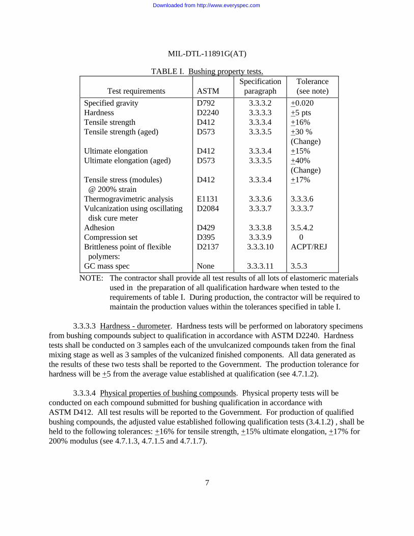
3.3.3 Track bushing characteristic tests. Table I has been established in order to identifythe compound performance characteristics/properties being provided for qualification for futurereference and production control purposes, pending successful qualification. Table I identifies therequirements for establishing the characteristics of the bushing compound(s). These tests will beperformed during the fabrication of the T130E1 long bushings (P/N 11678029) required forqualification and in accordance with the requirements established in Appendix A.
3.3.3.1 Specimen preparation. Specimens shall be prepared in accordance with theapplicable ASTM and shall be of an equivalent state of cure to that of the bushings submitted forendurance testing. The following tests will be performed on samples taken at the final mixing ofthe compound (see 4.3.1.1) and be of an equivalent state of cure as bushings submitted forqualification: specific gravity, hardness, tensile strength, elongation, tensile stress, agedproperties, brittleness point, cure meter, thermogravimetric analysis (TGA), load deflection,compression set and G/C mass spec. The following tests shall be performed on vulcanizedsamples: hardness, adhesion, and bushing endurance (see 4.3.1.2).
3.3.3.2 Specific gravity. Specific gravity tests will be performed on the bushingcompounds subject to qualification test in accordance with ASTM D792. Specific gravity testswill be performed on 3 samples from each compound submitted for qualification and all resultswill be provided to the Government. Samples shall be taken from unvulcanized compounds at thefinal mixing stage (see 4.7.1.1).
Downloaded from http://www.everyspec.com
MIL-DTL-11891G(AT)
7
TABLE I. Bushing property tests.
Test requirements ASTMSpecification
paragraphTolerance(see note)
Specified gravityHardnessTensile strengthTensile strength (aged)
Ultimate elongationUltimate elongation (aged)
Tensile stress (modules) @ 200% strainThermogravimetric analysisVulcanization using oscillating disk cure meterAdhesionCompression setBrittleness point of flexible polymers:GC mass spec
D792D2240D412D573
D412D573
D412
E1131D2084
D429D395D2137
None
3.3.3.23.3.3.33.3.3.43.3.3.5
3.3.3.43.3.3.5
3.3.3.4
3.3.3.63.3.3.7
3.3.3.83.3.3.93.3.3.10
3.3.3.11
+0.020+5 pts+16%+30 %(Change)+15%+40%(Change)+17%
3.3.3.63.3.3.7
3.5.4.2 0ACPT/REJ
3.5.3
NOTE: The contractor shall provide all test results of all lots of elastomeric materialsused in the preparation of all qualification hardware when tested to therequirements of table I. During production, the contractor will be required tomaintain the production values within the tolerances specified in table I.
3.3.3.3 Hardness - durometer. Hardness tests will be performed on laboratory specimensfrom bushing compounds subject to qualification in accordance with ASTM D2240. Hardnesstests shall be conducted on 3 samples each of the unvulcanized compounds taken from the finalmixing stage as well as 3 samples of the vulcanized finished components. All data generated asthe results of these two tests shall be reported to the Government. The production tolerance forhardness will be +5 from the average value established at qualification (see 4.7.1.2).
3.3.3.4 Physical properties of bushing compounds. Physical property tests will beconducted on each compound submitted for bushing qualification in accordance withASTM D412. All test results will be reported to the Government. For production of qualifiedbushing compounds, the adjusted value established following qualification tests (3.4.1.2) , shall beheld to the following tolerances: +16% for tensile strength, +15% ultimate elongation, +17% for200% modulus (see 4.7.1.3, 4.7.1.5 and 4.7.1.7).
Downloaded from http://www.everyspec.com
MIL-DTL-11891G(AT)
8
3.3.3.5 Aged physical properties. Aged physical property tests will be performed onspecimens taken from bushing compounds in accordance with ASTM D573. Accelerated agingshall be conducted for 166 + 2 hours at 158 + 3.6 degrees Fahrenheit (°F) or 70 to 72 hours at212°F + 3.6°F. All test results will be reported to the Government. The tolerance for the percentchange of unaged tensile strength to aged tensile strength will not exceed 30 percent duringproduction. The tolerance for the percent change of the unaged elongation to the aged elongationwill not exceed 40 percent during production (see 4.7.1.4 and 4.7.1.6).
3.3.3.6 Thermogravimetric analysis. This test will be performed in accordance withASTM E1131 during qualification to establish requirements for future reference during processcontrol. All test results will be reported to the Government. The ranges for TGA are as follows(see 4.7.1.8):
Plasticizer + Residue +3%Polymer +5%Filler +5%
3.3.3.7 Vulcanization using oscillating disk cure meter. A curing characteristics curve(trace) shall be obtained as outlined in ASTM D2084 on the bushing compound being submittedfor qualification. The traces will be provided to the Government. The following tolerances willbe used in production when compared to the charts representing traces of compounds used forfabrication of components for qualification. Parameter definitions shall be according toASTM D2084. Alternative test methods and parameter may be used but must be identified in thecontrol plan and approved by the Preparing Activity (see 4.7.1.9).
Minimum torque (M): +2 pound-inch (lb-in) [.23 Newton-meter (N-m)]Maximum torque (M): +4 lb-in (0.45 N-m)Time to 60 percent of M: T(60) + 0.4 minutesTime to reach 5 lb-in (0.57 N-m) above minimum torque: +0.4 minutes
3.3.3.8 Bushing adhesion test. Testing apparatus shall conform to ASTM D429,method B. A hub and spindle assembly is required for mounting the bushing insert (P/N 87565l9)that shall permit full rotation about a fixed axis. Three complete bushing assemblies (P/N11678029) shall be selected as the test samples and be of an equivalent state of cure to that of thebushings submitted for endurance test. Testing shall be conducted on the outer rings of thebushing assembly (see 4.7.1.10).
Downloaded from http://www.everyspec.com
MIL-DTL-11891G(AT)
9
3.3.3.8.1 Sample preparation. The bushings shall be prepared for testing by cutting therubber rings transversely down to the metal insert and separating circumferentially for a distancesufficient to permit a firm grip by the free end of the power-actuated clamp. Injection moldedbushings shall be cut on the sprue side (injection side) to ensure discontinuity (non-knit) of theelastomer is checked.
3.3.3.8.2 Procedure. The bushing shall be mounted on the pin in the hub and spindleassembly with the free end of the rubber firmly gripped by the machine clamp. The machine shallbe started and the rubber pulled circumferentially from the sleeve/insert. In the event theelastomer is about to tear off, specimens should be cut back to the metal. Force measurementsshall be recorded and observations made throughout the test to determine the minimum loadrequired to separate the rubber from the metal/adhesive interface or from the rubber itself.
3.3.3.8.3 Acceptance. Successful adhesions will be those that result in a separation in therubber (rubber tear) without evidence of separation in the rubber-to-metal interface. The bondbetween metal and all bonding agents/cements shall be higher than the bushing rubber so thatseparation during adhesion occurs only in the rubber. The load required to separate the ringsfrom the pin shall be not less than that shown in 3.5.4.2. For T130El bushing qualification aminimum of 29 pounds per inch of width is required. The elastomer pulled off the sleeve and thatremaining shall be examined for any defects including cracks, blisters, or porosity. Discontinuity(non-knit) of the elastomer resulting in any indication of separation of the elastomer shall be causefor rejection. All test results shall be reported to the Government.
3.3.3.9 Compression set. The bushing laboratory specimen shall be subjected to thecompression set test of method B of ASTM D395 for 22 + 0.5 hours at a temperature of158 + 3.6°F using type 1 specimens. Five specimens shall be tested with the average resultsreported in accordance with ASTM D395. The compression set shall not exceed 25 percent andall data shall be reported to the Government (see 4.7.1.11).
3.3.3.10 Brittleness point of flexible polymers. The specimens and test method shall be inaccordance with ASTM D2137. Specimens shall be type B of method A and tested at atemperature of -40 + 3.6°F in accordance with method A of ASTM D2137. Five specimens shallbe tested and inspected showing no evidence of cracks, fissures, or pinholes. In the event onespecimen fails, an additional five specimens shall be prepared and tested. Failure of two or moreof the initial five specimens, or any of the last five specimens, shall be cause for rejection. Testresults shall be reported to the Government (see 4.7.1.12).
3.3.3.11 GC mass spec. The Government may perform spot inspections for the purposeof obtaining samples for pyrolysis-gas chromatography/mass spectrometry analysis. Up to fivesamples may be taken at any time during a production contract. Samples will be taken from enditem cured parts. The initial part of the method will thermally desorb the additives, which are then
Downloaded from http://www.everyspec.com
MIL-DTL-11891G(AT)
10
analyzed by gas chromatography/mass spectrometry. Following desorption of the additives, theremaining sample will be pyrolyzed and analyzed by gas chromatography/mass spectrometry. Abaseline scan will be performed on the material submitted for qualification. Future results will becompared with the baseline to determine that there are no new peaks appearing, no ingredientsmissing and no substitutions in subsequent production runs (see 4.7.1.13).
3.3.4 Track roadwheel path and ground pad performance tests. All material propertytests indicated in table II for the track roadwheel path and ground side pads (integral and/orreplaceable) shall be conducted in accordance with the referenced ASTM's, the ProcessFingerprint Plan (see 3.3) and in accordance with the requirements of this specification. Thefollowing tests will be performed on qualification samples taken on unvulcanized samples at thefinal mixing of the compound (see 4.3.1.3) and be of an equivalent state of cure as compoundsbeing submitted for qualification: specific gravity, hardness, tensile strength, elongation, tensilestress, aged properties, brittleness point, cure meter; ozone resistance, TGA, GC mass spec. Thefollowing tests will be performed on qualification samples taken on vulcanized samples: hardness,tensile strength, elongation, tensile stress, aged properties, ozone resistance, adhesion, and blow-out (see 4.3.1.4).
3.3.4.1 Specific gravity. Specific gravity tests will be performed on the pad (integraland/or replaceable) and roadwheel path compounds subject to qualification test in accordancewith ASTM D792. Specific gravity tests will be performed on a minimum of 3 samples from eachcompound submitted for qualification and all results provided to the Government. Samples shallbe taken from unvulcanized compounds at the final mixing stage (see 4.7.2.1).
3.3.4.2 Hardness - durometer. Hardness tests will be performed on laboratory specimensof pads (integral and/or replaceable) and roadwheel path compounds subject to qualification inaccordance with ASTM D2240. As a minimum, hardness tests shall be conducted on 3 sampleseach of the unvulcanized compounds taken from the final mixing stage as well as 3 samples of thefinished components. The results of all tests shall be provided to the Government (see 4.7.2.2).
3.3.4.3 Physical properties of pad and roadwheel path compounds. Physical propertytests, as a minimum, will be conducted on specimens taken from each compound used in the pads(integral and replaceable) and roadwheel path in accordance with ASTM D412, table II andfigures 1, 2, 3 and 4. The three specimens for the style B (Tl54) ground pad shall be taken asshown in figure 1. The three specimens for the style B (TI54) roadwheel path shall be taken asshown in figure 2. The three specimens for the style A (Tl07) ground pad shall be taken as shownin figure 3. The three specimens for the style A (Tl07) roadwheel path shall be taken as shown infigure 4. The three specimens for the style B (T157I) ground pad shall be taken as shown infigure 6. All test results will be reported to the Government. The production tolerance for thephysical property tests based on the average values established during qualification tests will be+15% for tensile strength, +15% ultimate elongation, and +15% for 200% modulus (see 4.7.2.3,4.7.2.5 and 4.7.2.7).
Downloaded from http://www.everyspec.com

MIL-DTL-11891G(AT)
11
TABLE II. Material property tests.
Test requirementASTM
test methodSpecification paragraph
Tolerance(see note)
Specific gravity D792 3.3.4.1 +0.020Hardness D2240 3.3.4.2 +5 ptsTensile strength D412 3.3.4.3 +15%Tensile strength (aged) D573 3.3.4.4 +30%
(Change)Ultimate elongation D412 3.3.4.3 +15%Ultimate elongation (aged) D573 3.3.4.4 +40%
(Change)Tensile stress (modulus) @ 200% strainThermogravimetric analysisVulcanization using oscillating disk cure meterAdhesion style A & B ground side padsAdhesion type I & II (roadwheel path)Ozone resistanceOzone resistanceBrittleness point of flexible polymersGC mass specBlowout test style A
D412
E1131D2084
D429
D429
D1149NoneD2137
NoneNone
3.3.4.3
3.3.4.53.3.4.6
3.3.4.7
3.3.4.7
3.3.4.83.3.4.93.3.4.10
3.3.4.113.3.4.12
+15%
3.3.4.53.3.4.6
0
0
ACPT/REJACPT/REJACPT/REJ
3.5.3ACPT/REJ
NOTE: The contractor shall provide all test results of all lots of elastomeric materials used inthe preparation of all qualification hardware when tested to the requirements oftable II. During production, the contractor will be required to maintain theproduction values within the tolerances specified in table II.
3.3.4.4 After age physical properties. Physical property tests, as a minimum, will beconducted on 3 aged specimens taken from each compound used in the pads (integral andreplaceable) and roadwheel path in accordance with ASTM D573, table II and figures 1, 2, 3,and 4. Three specimens for each test are required and all results will be reported to theGovernment. Accelerated aging shall be conducted for 166 + 2 hours at 158 + 3.60°F or 70 to72 hours at 212 + 3.60°F. The production tolerance for the percent change of unaged tensilestrength (see 3.3.4.3) to aged tensile strength will not exceed +30 percent. The tolerance for thepercent change of the unaged elongation (see 3.3.4.3) to the aged elongation will not exceed+40 percent (see 4.7.2.4 and 4.7.2.6).
Downloaded from http://www.everyspec.com

MIL-DTL-11891G(AT)
12
3.3.4.5 Thermogravimetric analysis. This test will be performed in accordance withASTM E1131 during qualification to establish requirements for future reference duringproduction. Results of the TGA will be provided to the Government. The ranges for TGA are asfollows (see 4.7.2.8):
Plasticizer + Residue...............................+3%Polymer...................................................+5%Filler........................................................+5%
3.3.4.6 Test measurements with oscillating disk cure meter. A curing characteristicscurve (trace) shall be obtained as outlined in ASTM D2084 on the compounds used in the pad(integral and/or replaceable) and roadwheel path of the track being submitted for qualification. The traces will be provided to the Government. The following tolerances will be used inproduction when compared to the charts representing traces of compounds used for fabrication ofcomponents for qualification. Parameter definitions shall be according to ASTM D2084. Alternative test methods and parameters may be used but must be identified in the control planand approved by the Preparing Activity (see 4.7.2.9).
Minimum torque (M): +2 lb-in (0.23 N-m)Maximum torque (M): +4 lb-in (0.45 N-m)Time to 60 percent of M: T(60) + 0.4 minutesTime to reach 5 lb-in (0.57 N-m) above minimum torque: +0.4 minutes
3.3.4.7 Track pad and roadwheel path adhesion test. Adhesion tests will be conducted onthe finished products of the track systems being submitted for qualification. As a minimum, tworepresentative samples of the ground pad (replaceable and/or integral) and two representativesamples of the roadwheel path elastomer are required for the adhesion tests. One test specimenfrom each component shall be prepared for test in accordance with 3.3.4.7.1 using the testapparatus of ASTM D429, method B (see 4.7.2.10).
3.3.4.7.1 Sample preparation. The samples shall be prepared in the location as shown infigures 1, 2, 3 and 4. The elastomer shall be cut down to the base metal along two (2) parallellines, leaving an elastomer strip 1 + 1/16 inch in width, 1/2 to 1 inch in thickness, with lengthextending in the direction of maximum adhesive area. The elastomeric thickness shall be asuniform as practical of the thickness shown in the respective figures for the component under test. When necessary, the portion of the elastomer remaining outside of the 1-inch wide section of thecut strip shall be removed from the metal base to avoid any edge constraint during the test. Theelastomer shall be stripped from the metal using a sharp knife for a sufficient distance to permitfirm gripping of the tab in the grip of the test machine head.
Downloaded from http://www.everyspec.com

MIL-DTL-11891G(AT)
13
3.3.4.7.2 Procedure. The metal base of the specimen shall be mounted to one head of thetesting machine using care in centering and adjustment so that the tension shall be uniformlydistributed across the strip width. The machine shall then be started and, when the applied forcecauses the elastomer to begin separating from the metal, the recorder shall be started. Force shallcontinue to be applied and recorded continuously throughout the test. The point of separation ofthe elastomer from the metal shall be observed carefully throughout the test. In the event thattearing up into the elastomer occurs, the specimen should be cut back to the metal withoutstopping the machine.
3.3.4.7.3 Acceptance. The roadwheel path adhesion shall be not less than 60 pounds perinch of width and the pad adhesion shall not be less than 120 pounds per inch of width. Successful adhesions will be those that result in a separation in the rubber (rubber tear) withoutevidence of separation in the rubber-to-metal interface. The bond between metal and all bondingagents/cements shall be higher than the component compound so that separation during adhesiontests occurs only in the rubber. The elastomer pulled off the metal plate/shoe body and thatremaining shall be examined for any defects including cracks, blisters, or porosity. Discontinuity(non-knit) of the elastomer resulting in any indication of separation of the elastomer shall be causefor rejection. All data generated during this test will be provided to the Government.
3.3.4.8 Ozone resistance. Prepare specimens in accordance with procedure B ofASTM D518. The specimens shall be smoothly finished in accordance with ASTM D3182 andASTM D3183 and obtained from either of the following (see 4.7.2.11):
a. Three samples each shall be taken from each compound used on the trackroadwheel path and ground pad (integral and/or replaceable) and shall not includeany outer surface.
b. Samples may be taken from each uncured compound production molding blanks,prepared in the form of ASTM tensile slabs, and certified as being of an equivalentstate of cure as the production molded component (roadwheel path stock andground pad).
3.3.4.8.1 Procedure. Specimens shall be tested in accordance with ASTM D1149 andmounted in accordance with procedure B of ASTM D518, except the length of the clampingstrips shall be such as to facilitate placement within the ozone chamber. Specimens shall then beplaced in the chamber and exposed for 7 days at a temperature of 104 + 3.6°F having a partialpressure of ozone of 50 millipascals. The specimens shall show no evidence of cracks wheninspected at seven power magnification. Test results will be reported to the Government.
3.3.4.9 Optional ozone test procedure. As an option, the following procedures may beused in place of the above to accommodate the ozone test requirement (see 4.7.2.11).
Downloaded from http://www.everyspec.com

MIL-DTL-11891G(AT)
14
3.3.4.9.1 Specimen preparation. The size of the specimens shall be in accordance withprocedure B of ASTM D518, except the thickness shall be 0.080 + 0.005 inch. Specimens shallbe obtained from either of the following:
a. Three specimens shall be taken from the track block chevron and shall not includeany outer surface.
b. Three specimens shall be taken from production molding blanks of uncured rubbercompounds, being used to rubberize track components, prepared in the form ofASTM tensile slabs and certified as being of an equivalent state of cure as theproduction molding.
3.3.4.9.2 Procedure. The specimen shall be tested in accordance with procedure B ofASTM D518, except the length of the clamping strips shall be such as to facilitate placementwithin the ozone chamber. Specimens shall then be placed in the chamber and exposed for 7 daysat a temperature of 100 + 2°F in an air-ozone mixture containing 50 + 5 parts by volume of ozoneper hundred million parts of air. The specimen surfaces shall be finished smoothly and of uniformthickness in accordance with part C of ASTM method D-15. The rubber materials shall have noevidence of cracks when inspected at 7 power magnification at the end of 7 days.
3.3.4.10 Brittleness point of flexible polymers. The specimens and test method shall be inaccordance with ASTM D2137. Specimens shall be type B of method A and tested at atemperature of -40 + 3.6°F in accordance with method A of ASTM D2137. Five specimens shallbe tested and inspected showing no evidence of cracks, fissures, or pinholes. In the event onespecimen fails, an additional five specimens shall be prepared and tested. Failure of two or moreof the initial five specimens, or any of the last five specimens, shall be cause for rejection. Testresults shall be reported to the Government (see 4.7.2.12).
3.3.4.11 GC mass spec. The Government may perform spot inspections for the purposeof obtaining samples for pyrolysis-gas chromatography/mass spectrometry analysis. Up to fivesamples may be taken at any time during a production contract. Samples will be taken from enditem cured parts. The initial part of the method will thermally desorb the additives, which are thenanalyzed by gas chromatography/mass spectrometry. Following desorption of the additives theremaining sample will be pyrolyzed and analyzed by gas chromatography/mass spectrometry. Abaseline scan will be performed on the material submitted for qualification. Future results will becompared with the baseline to determine that there are no new peaks appearing, no ingredientsmissing, and no substitutions in subsequent production runs (see 4.7.2.13).
3.3.4.12 Track blowout test. This test is required for compounds being submitted forqualification for integral pad track systems using the T107 track as the candidate qualificationdesign. Testing shall be conducted at the U.S. Army Tank-automotive and Armaments Commandand arrangements can be made by contacting the preparing activity. Testing will be conducted on
Downloaded from http://www.everyspec.com

MIL-DTL-11891G(AT)
15
a fatigue test machine (see 4.7.2.14) having a static load and a dynamic (oscillating) load asspecified in 3.3.4.12a below as applicable. Cyclic loading will be at 1800 cycles per minute withautomatic load sensing and compensation capability. Fifteen (15) track block samples of eachcompound being submitted for qualification will be required with 12 being tested. The highestand lowest cycles to failure will not be counted and the results will be the average of theremaining ten (10) track block samples. All test results will be provided to the submittingcontractor indicating acceptance or rejection of the samples (see 4.7.2.14).
a. T107 ground side chevron pads are to be subjected to a dynamic load of1600 pounds and a static load of 1600 pounds for a total load of 3200 pounds. The minimum average fatigue life (blowout) shall not be less than 50 000 cycleswith no individual block of the original twelve (12) samples below 45 000 cycles.
3.3.4.13 Product marking. Unless otherwise specified (see 6.2), each track shoe assembly(roadwheel path elastomer) and track shoe pad (replaceable or integral) shall have the followinginformation permanently and plainly marked on it. Every attempt possible should be made tolocate this information in an area that may not get damaged/worn during field use.
a. Manufacturer's name or rubber manufacturer's code number.b. National stock number of the track shoe assembly and/or track shoe pad kit as
applicable.c. Week of month and year of manufacture.d. Compound number and mold number.
3.4 Phase III endurance tests.
3.4.1 Bushing endurance. The bushing qualification/endurance testing will be conductedin accordance with the test requirements of Appendix A and results provided to the Government.Compounds that have passed all qualification test requirements and have documented datasupporting compliance to all requirements will be listed on the QPL by number and source for alltrack bushings with the exception of T158 and T158LL track systems.
3.4.1.1 Endurance test requirements. The bushing endurance test for qualification will beconducted in accordance with the requirements of Appendix A. The minimum acceptance criteriafor fatigue life-to-failure for all 9 specimens tested is 110 000 compression load cyclessimultaneous with 440 000 torsional cycles without exceeding 0.144 inches of radial deflection atthe bushing center line. The minimum average of 8 specimens, dropping the highest bushing testcycles, shall not be less than 130 000 cycles.
3.4.1.2 Process Fingerprint Plan. Following qualification and prior to any production, thecontractor’s Process Fingerprint Plan (see 3.3) with the predicted and actual target values andranges shall be reviewed by the contractor with the Government QAR to determine whether any
Downloaded from http://www.everyspec.com
MIL-DTL-11891G(AT)
16
adjustments are required and the extent of any adjustments. Any and all pertinent and relevantdata, historical or otherwise, shall be used as supporting rational for the establishment of thesevalues. This final plan shall be reviewed by the Government and signed by the QAR and anauthorized contractor representative. This plan will then be put in place at the contractor'splant/facilities and/or subcontractor's plant/facilities and utilized for the production of allsubsequent parts/assemblies as described in the plan.
3.4.2 Replaceable pad track system qualification. Contractors submitting compounds forqualification to produce style B, replaceable pad track systems are responsible for the entire tracksystem to include all metal components and fasteners. All requirements of 3.2 must be met priorto qualification approval and the documented results provided to the Government.
3.4.2.1 Endurance test requirements. Full track assemblies being submitted forqualification must contain a qualified pin/bushing assembly. A report is required containing theinformation required in 3.3.2 and 3.4.1 as demonstration of bushing qualification. In addition, areport containing the results of 3.3.3 and 3.3.4 of this specification is also required as applicableto replaceable pad track systems. Track system qualification will be conducted in accordancewith the requirements established in Appendix B. A minimum of 5000 miles demonstrated trackdurability at 20 % replacement must be achieved for a track system to be considered qualified anda contractor to be listed on the QPL.
3.4.2.2 Track ground pad qualification. Contractors submitting compounds for pads onlyon style B track will provide the inspection results in accordance with the requirements of 3.2 andprovide a report containing the results of applicable requirements of 3.3.4. Excluding the T157Ipad, on-vehicle qualification tests will be conducted in accordance with Appendix B as applicableto ground pads only. A minimum of 1000 miles demonstrated track pad durability at 40%replacement must be achieved for a pad compound/contractor to be considered for listing on theQPL for pads. For the T157I pad, on-vehicle qualification tests will be conducted in accordancewith Appendix D. A minimum of 800 miles demonstrated track pad durability at 40%replacement must be achieved for a pad compound/contractor to be considered for listing on theQPL for pads.
3.4.3 Integral pad track system qualification. Contractors submitting compounds forqualification to produce style A, integral pad track systems are responsible for the entire tracksystem to include all metal components and fasteners. All requirements of 3.2 must be met priorto qualification approval and the documented results provided to the Government.
3.4.3.1 Endurance test requirements. Full track assemblies being submitted forqualification must contain a qualified pin/bushing assembly. A report containing the informationrequired in 3.3.2 and 3.4.1 is required as demonstration of bushing qualification. In addition, areport on the results of 3.3.3 and 3.3.4 of this specification is also required as applicable forintegral pad track systems. Track system qualification will be conducted in accordance with the
Downloaded from http://www.everyspec.com

MIL-DTL-11891G(AT)
17
requirements established in Appendix C. A minimum of 1200 miles demonstrated track durabilityat 20% replacement must be achieved for a track system to be considered qualified and acontractor to be listed on the QPL.
3.5 Production requirements. Following qualification and prior to any production, thecontractor's Process Fingerprint Plan (see 3.3) with the predicted and actual target values andranges shall be reviewed by the contractor with the Government QAR to determine whether anyadjustments are required and the extent of any adjustments. All data generated during thequalification of track bushings, track pads, and full track assemblies as required and in accordancewith 3.3 shall be used in the assessment of any changes to the contractor's Process FingerprintPlan. This final plan shall be approved by the Government, signed by the QAR and an authorizedcontractor representative, and dated. This plan will then be put in place at the contractor'splant/facilities and/or subcontractor's plant/facilities and utilized for the production of allsubsequent parts/assemblies as described in the plan. During production, the contractor shallmaintain values within the tolerances specified in the Process Fingerprint Plan.
3.5.1 First article. When specified (see 6.2), a sample shall be subjected to first articletest/inspection in accordance with 4.4.
3.5.2 Workmanship. Workmanship shall be of such quality as to assure that trackpin/bushing assemblies, track shoe pads and track shoe assemblies furnished under thisspecification are free from defects that compromise, limit or reduce performance in intended use.The bushing holes of the shoes shall be free from foreign substances that will adversely affectbushing installation and endurance. The shoe shall be free from sharp edges, concave roadwheelpath surfaces, or other irregularities which may adversely affect operation. Molded elastomericcomponents shall be free from blisters, cracks, folds, porosity, backrinding, flash, and non-fill (aircheck), voids, cuts, foreign material, separation, off-register, undercure, overcure, and improperdimensions. Bushing rubber shall be free from installation cuts and tears. Additional information,guidance and a listing of unacceptable defects are shown in table VI. Note that no defects areallowed on bushing assemblies.
3.5.3 GC mass spec. The Government may perform spot inspections for the purpose ofobtaining samples for pyrolysis-gas chromatography/mass spectrometry analysis. Up to fivesamples may be taken at any time during a production contract. Samples will be taken from enditem cured parts. The initial part of the method will thermally desorb the additives, which are thenanalyzed by gas chromatography/mass spectrometry. Following desorption of the additives, theremaining sample will be pyrolyzed and analyzed by gas chromatography/mass spectrometry. Abaseline scan will be performed on the material submitted for qualification. Future results will becompared with the baseline to determine that there are no new peaks appearing, no ingredientsmissing, and no substitutions in subsequent production runs.
Downloaded from http://www.everyspec.com

MIL-DTL-11891G(AT)
18
3.5.4 Pin/bushing design and construction. Unless otherwise specified (see 6.2),(reference dimensioned bushing drawings) the thickness of the elastomeric sections bonded to thepin shall be such that compression of 35 to 40 percent of the original thickness will result wheninstalled in the intended application. Unless otherwise specified, the width of the sections shall benot less than two and one-half or more than three times their thickness before compression. Thecontractor shall be responsible for the volume of bushing properly filling the total volume forwhich it is intended within +5 percent (95 to 105 percent of available volume). The bushing shallnot protrude beyond nor be recessed inside the shoe in which it is assembled beyond the limitsshown on applicable drawings. Unless otherwise specified, the bushing bore of the track shoebody shall have a surface roughness height between 63 and 250 microinches (see 4.7.1.14).
3.5.4.1 Concentricity. The pin with the elastomer bushing thereon, assembled in theapplicable shoe (or simulated bore), shall be concentric with the bore of the shoe (or simulatedbore), so that the elastomer thickness is uniform within +1/64 inch.
3.5.4.2 Bushing adhesion. When tested in accordance with 4.7.1.10, the load required toseparate the elastomeric sections from the pin/sleeve shall be not less than the values shownbelow. The elastomer pulled off and that remaining on the part shall show no evidence of anydefects including cracks, blistering, or porosity at the conclusion of the test. Discontinuity(non-knit) of the elastomer resulting in any indication of separation of the elastomer shall be causefor rejection.
Diameter of pin Minimum load (inches) (lbs/inch width)
5/8 233/4 251 291-1/8 311-1/4 331-5/16 342 36
NOTE: When exact size of pin/sleeve is not shown above, use the value of load for thenext larger pin/sleeve diameter.
Downloaded from http://www.everyspec.com
MIL-DTL-11891G(AT)
19
4. VERIFICATION
4.1 Classification of inspection. The inspection requirements specified herein areclassified as follows:
a. Qualification inspection (see 4.3)b. First article inspection (see 4.4)c. In-process inspections and tests (see 4.5.2)d. Conformance inspection (CI) (see 4.5.3)e. Control tests (see 4.6)
4.2 Inspection conditions. All inspections shall be performed in accordance withconditions specified in applicable drawings, specifications, and standards.
4.3 Qualification inspection.
4.3.1 Sampling for qualification inspection. Qualification inspection shall be performedon sample units selected in accordance with table III for bushings and table IV for trackroadwheel path and ground pad rubber which were produced with equipment and proceduresnormally used in production. The test results and other inspection information will be submittedto the Government to be used for the establishment of average values for future productioncontrol. Established property and tolerances in tables I and II must be met by qualificationspecimens subjected to applicable tests. Upon successful fabrication and qualification of allcomponents and tracks, contractors shall not make any compound formulation changes in eitherthe type or the quantity of ingredients without prior Government approval.
4.3.1.1 Bushings (unvulcanized). Samples from unvulcanized bushings shall be takenupon final compound mixing for the performance of the following qualification tests: specificgravity, hardness, tensile strength, elongation, tensile stress, aged properties, brittleness point,cure meter, TGA, compression set, GC mass.
4.3.1.2 Bushings (vulcanized). The following tests will be performed on vulcanizedbushings: hardness, adhesions, bushing endurance.
4.3.1.3 Roadwheel path and ground pad (unvulcanized). Samples from unvulcanizedroadwheel path and ground pad rubber shall be taken upon final compound mixing for theperformance of the following qualification tests: specific gravity, hardness, tensile strength,elongation, tensile stress, aged tensile strength (roadwheel path only), aged elongation (roadwheelpath only), brittleness point, cure meter, ozone resistance, TGA, and GC mass.
Downloaded from http://www.everyspec.com

MIL-DTL-11891G(AT)
20
TABLE III. Classification of inspection and frequencies (bushings).
TitleRequire-
ment Inspection QualificationFirst
articleIn-processinspection CI
Controltest
Specific gravity 3.3.3.2 4.7.1.1 1/ 1/ 1/ BatchHardness 3.3.3.3 4.7.1.2 1/ 1/ 1/ Shift 1/ShiftTensile strength 3.3.3.4 4.7.1.3 1/ 1/ 1/ ShiftTensile strength
(aged)3.3.3.5 4.7.1.4 1/ 1/ 1/ Month
Ultimate elongation 3.3.3.4 4.7.1.5 1/ 1/ 1/ ShiftUltimate elongation
(aged)3.3.3.5 4.7.1.6 1/ 1/ 1/ Month
Tensile stress 3.3.3.4 4.7.1.7 1/ 1/ 1/ ShiftTGA 3.3.3.6 4.7.1.8 1/ 1/ 1/ Bi-MonthlyCure meterAdhesionCompression setBrittlenessGC mass specBushing fill
ConcentricityWorkmanshipProduct markingEndurance
3.3.3.73.3.3.83.3.3.93.3.3.103.3.3.11
3.5.4
3.5.4.13.5.2
3.3.4.133.4.1
4.7.1.94.7.1.104.7.1.114.7.1.124.7.1.134.7.1.14
4.7.1.154.5.3.14.5.3.14.3.3
1/1/1/1/1/
1/Mold
2/2/2/1/
1/1/1/1/1/
1/Mold
2/2/2/
1/ Batch
1/ Month1/ Monthly
2/2/2/
1/Shift
4/1/NewMold
3/
NOTES:1/ Samples shall be taken as specified in section 3. Unless otherwise specified (see 6.2),
sample size shall be one.2/ Sample size shall be in accordance with table V.3/ Bushing endurance shall be run as specified by the Procuring Activity. During the
course of any given contract, no more than three (3) tests shall be required. Requirements and sample size shall be in accordance with 3.4.1.
4/ The Government may require samples as specified in 3.3.3.11.5/ One batch is identified as a full mixer of rubber compound. 1/batch indicates one
sample per batch. 1/bi-monthly indicates one sample every other month.6/ Samples shall be selected at the location specified in 4.3.1.1 and 4.3.1.2. For
in-process tests, samples are picked right after or while batches are being finalized. Control Tests would normally be performed on finished bushings (vulcanized).
Downloaded from http://www.everyspec.com

MIL-DTL-11891G(AT)
21
TABLE IV. Classification of inspections and frequencies (roadwheel path and ground pad).
TitleRequire-
ment Inspection QualificationFirst
articleIn processInspection CI
Controltest
Specific gravity 3.3.4.1 4.7.2.1 1/ 1/ 1/ BatchHardness 3.3.4.2 4.7.2.2 1/ 1/ 1/Shift 1/ShiftTensile strength 3.3.4.3 4.7.2.3 1/ 1/ 1/Shift 1/WeekTensile strength
(aged)3.3.4.4 4.7.2.4 1/ 1/ 1/Month 1/Month
Ultimateelongation
3.3.4.3 4.7.2.5 1/ 1/ 1/Shift 1/Week
Ultimateelongation(aged)
Tensile stressTGACure meterAdhesionOzone
resistanceBrittlenessGC mass specBlowoutWorkmanshipProduct
markingRoad test
3.3.4.4
3.3.4.33.3.4.53.3.4.63.3.4.73.3.4.83.3.4.9
3.3.4.103.3.4.113.3.4.12
3.5.23.3.4.13
3.4.2.1
4.7.2.6
4.7.2.74.7.2.84.7.2.94.7.2.104.7.2.11
4.7.2.124.7.2.134.7.2.144.5.3.14.5.3.1
4.3.2
1/
1/1/1/1/1/
1/1/1/2/2/
1/
1/
1/1/1/1/1/
1/1/1/2/2/
1/Month
1/Shift1/Bi-Monthly
1/Batch
1/Month
2/2/
1/Month
1/Week
1/Shift1/Month
4/3/
NOTES:1/ Samples shall be taken as specified in section 3. Unless otherwise specified (see 6.2),
sample size shall be one.2/ Sample size shall be taken in accordance with table V.3/ Samples shall be required by the Government as specified in 3.3.4.12.4/ Samples may be selected by the Government as specified in 3.3.4.11.5/ One batch is identified as a full mixer of rubber compound. “1/batch” indicates one
sample per batch. “1/bi-monthly” indicates one sample every other month.6/ Samples for in-process and control testing shall be selected at the locations as specified in
4.3.1.3 and 4.3.1.4. In-process tests shall normally be performed on finished batches. Control tests shall be performed primarily on finished pads and roadwheel path rubber.
Downloaded from http://www.everyspec.com

MIL-DTL-11891G(AT)
22
4.3.1.4 Roadwheel path and ground pad (vulcanized). The following qualification testswill be performed on vulcanized track roadwheel path rubber and ground pads: hardness, tensilestrength (replaceable and integral pads only), elongation (replaceable and integral pads only),tensile stress (replaceable and integral pads only), aged tensile strength (replaceable and integralpads only), aged elongation (replaceable and integral pads only), ozone resistance, adhesion, andblowout.
4.3.1.5 Samples for on-vehicle road test. On-vehicle road test qualification of replaceablepad track systems (T154) requires 74 complete assemblies plus spares in accordance withAppendix B. Excluding the T157I pads, contractors supplying pads only for qualification arerequired to provide 74 pads plus spares in accordance with Appendix B. Contractors supplyingpads for T157I pad qualification are required to submit 164 samples plus spares in accordancewith Appendix D. On-vehicle road test qualification of integral pad track systems (Tl07) requires50 complete assemblies plus spares in accordance with Appendix C. In addition 15 blocks arerequired for blow-out testing in accordance with 3.3.4.12. All hardware submitted for on-vehiclequalification shall be sent to the test site. Results of all tests listed in tables I and II shall be on filefor the on-vehicle test samples. The samples shall be representative of those produced withequipment and procedures normally used in production.
4.3.1.5.1 Qualification sample size. The Government reserves the right to adjust thequalification sample size specified in 4.3.1.5 based on vehicle availability and the number ofcontractors attempting qualification.
4.3.2 On-vehicle-testing. For the on-vehicle test, replaceable track pad systems shall bequalified on the T154 track configuration mounted on an M109 series vehicles (see Appendix Bfor the replaceable track pad system test plan). Integral pad track shall be qualified on the T107track mounted on an M88 series vehicle system (see Appendix C for the integral pad track testplan). Extension of qualification to track models other than those directly tested are listed in6.7.1. The T157I pads shall be qualified on a Bradley Fighting Vehicle (BFV) System. SeeAppendix D for the T157I pad test plan.
4.3.3 Qualification approval. Track assemblies shall meet the requirements stated insection 3. Failure to meet minimum requirements specified shall be cause for sample rejection. Failure of any qualification sample to pass the specified inspections may be cause for refusal bythe Government to conduct additional inspections until it has been proved, to the satisfaction ofthe Preparing Activity, that the faults revealed by the inspections have been corrected.
4.3.4 Retention of qualification. The Preparing Activity shall periodically review thecontractor's test and inspection data during the life of future production contracts to assure thatthe results are equal or superior to those obtained during qualification testing. Any test results
Downloaded from http://www.everyspec.com
MIL-DTL-11891G(AT)
23
that continue to fail to match or exceed the data requirements established during qualificationtesting may be cause for removal of the contractor from the QPL. For those contractors who areon the QPL, but have been out of production for 1 (one) year or more, the Government reservesthe right to require a first article inspection (see 4.4).
4.4 First article inspection.
4.4.1 First article sample. Unless otherwise specified (see 6.2 and 6.10), the Governmentshall select bushing and roadwheel path and ground pad samples produced under the productioncontract for first article inspection. For bushings, first article samples shall be inspected asspecified in table III. For track roadwheel path and ground path, first article samples shall beinspected to table IV. Inspection results shall be equal or superior to those obtained duringqualification testing.
4.4.2 First article sample approval. Approval of the first article sample by theGovernment shall not relieve the contractor of his obligation to supply bushings, roadwheel pathor ground pad items that are fully representative of those inspected as a first article sample. Anychanges or deviations of the production units from the first article sample shall be subject to theapproval of the contracting officer.
4.4.3 Failure. Deficiencies occurring during or as a result of first article inspection shallbe cause for rejection of the products until evidence has been provided by the contractor thatcorrective action has been taken to eliminate the deficiency. The Government will not acceptproducts until first article inspection is completed to the satisfaction of the Government. Further,the Government reserves the right to remove a contractor's name from the QPL pendingsuccessful completion of the first article.
4.5 Product and process control.
4.5.1 Control plan. The control plan is basically an outline of how the contractor verifiesfulfillment of the requirements of this specification. The control plan shall summarize the controltechniques used from receipt of raw materials to shipment of product. Test/inspectioncharacteristic values shall be identified in the Process Fingerprint Plan (see 3.3). The initialcontrol plan shall be established prior to qualification and shall reflect the product and processcontrols used to manufacture the qualification hardware. The control plan shall be in chart formand shall reflect the following: supplier name, process or product name and/or number, planrevision and revision date, operation number or process step, process parameters and productcharacteristics, method of control (e.g. gage, test, etc), sample size and frequency, analysismethod (e.g. control chart, lot plot, run chart, etc), and other important control information. Thecontrol plan shall address the test methods/equipment used to meet the requirements of thisspecification. The use of alternative test methods/equipment (state-of-the-art) may be utilizedprovided supporting data/rationale is provided to show equivalency to the test/equipment being
Downloaded from http://www.everyspec.com

MIL-DTL-11891G(AT)
24
replaced and the contractor receives Government approval (see 3.3). The plans shall reflect theprocess parameter controls (see 4.5.1.1) and product characteristic controls (see 4.5.1.2) used toassure the quality of the end product. The control plans are intended to be dynamic and may bechanged as process improvements are made. The initial plans shall be delivered to theGovernment QAR and the Preparing Activity for approval. Any changes to the plans shall beprovided to the Government QAR for concurrence, prior to implementation. The contractor shallhave data available to support any changes to the control plans.
4.5.1.1 Process parameter controls. The quality of the products produced under thisspecification shall be controlled through process control techniques, such as statistical processcontrol (SPC). Process controls shall be of a type that will provide adequate control of theprocess. The type and extent of the control is a function of the significance of the parameterbeing controlled.
4.5.1.1.1 Process parameter selection. The process parameters selected for control shallbe identified through one of the following process analysis methods: Design of Experiments(DOE), Regression Analysis, Correlation Studies, Failure Mode Effects Analysis, (FMEA) , orother formal or scientific process analysis technique. The results of the process analysis shall bedocumented. As a minimum, the contractor shall identify how the following parameters are to becontrolled or provide data from the process analysis or other evidence/information that justifieswhy one of the following are not controlled: raw material properties, material weights, mixingand milling conditions (time, temperature, mill banks, etc.) stock lay down temperatures,extrusion temperatures, booking temperatures, unvulcanized rubber block weights/dimensions,cleanliness of rubber and metal to be bonded, complete adhesive coverage, injection time, curetime, mold service time, runner temperature, nozzle temperature, mold temperature, moldpressure. In addition, the contractor may use any additional parameters to assure production ofacceptable track components. The selected parameters shall be reflected on the control plan(s).
4.5.1.2 Product characteristic controls. Product characteristics are identified in thetechnical data package and in this specification. The product characteristics identified shall becontrolled by process control techniques. Adequate process controls are necessary for thereduction and elimination of these product characteristic inspections as described in 4.5.1 of thisspecification.
4.5.1.2.1 Product characteristic selection. As a minimum, the product characteristics tobe controlled or tested are identified in Quality Assurance Provisions, drawings, and thisspecification (see 4.5.3 and 4.7). At its own discretion, the contractor may control or inspect anyadditional characteristics. However, elimination of the required characteristics shall be supportedby adequate inspection process analysis data. The selected characteristics shall be reflected on thecontrol plan.
Downloaded from http://www.everyspec.com

MIL-DTL-11891G(AT)
25
4.5.2 In-process inspection. In-process inspections listed in tables III and IV shall beperformed on unvulcanized bushing, track roadwheel path and ground pad compound batches assoon as possible after they are final (all ingredients are added to the compounds). This effort willminimize production of large quantities of defective compounds which may result in theproduction of defective track components.
4.5.2.1 Sampling for in-process inspection.
4.5.2.1.1 Bushings. The samples for in-process inspection shall be selected and tested inaccordance with table III.
4.5.2.1.2 Roadwheel path and ground path. The samples for in-process inspection shallbe selected and tested in accordance with table IV.
4.5.2.2 Rework (workaway). Rubber track compounds that are defective ormiscompounded shall not be used for rework (workaway) to fabricate any track components. Rework will be limited to conforming compounds that are generated during processing. Reworkwill consist of compounds being reworked into the same compounds using the lowest practicallevel in order to avoid process, compound and finished product variation. This level shall beestablished by the contractor and shall not affect the rubber properties or result in processingdifficulties. Rubber compounds for rework would normally be limited to the following:
a. Non-defective compounds being worked into themselves at the rate indicatedabove.
b. Excess rubber left on the mills after extrusion, provided it is sheeted off promptly,identified and kept clean.
c. Extruded rubber that failed to meet dimensions, provided the extruded rubber ismilled, cooled and identified.
d. Rubber used to warm up the tuber, but has not been contaminated with otherrubber compound or scorched material.
4.5.2.3 Material weight tolerances. The ingredients shall be properly weighed oncalibrated scales and controlled by inspections to assure compliance to the tolerances andinspection frequencies established by the contractor. The weights of all ingredients for the masterbatches, remills (if any), and final batches shall be inspected to assure process control.
4.5.2.4 Vulcanization time, pressure and temperature. The vulcanization time,temperature, pressure and other cure conditions will be those established by contractors to assurethat track components have acceptable properties. These established cure conditions andtolerances will continue to produce components with acceptable properties and will meet the
Downloaded from http://www.everyspec.com

MIL-DTL-11891G(AT)
26
requirements of this specification. The molding pressure will be set and be maintained by themanufacturers to assure production of defect free components that will meet all specificationrequirements. The values for vulcanization time, pressure and temperature shall be identified inthe Process Fingerprint Plan (see 3.3).
4.5.2.5 Failures. Control failures are indicated by a deficiency discovered at any processcontrol point (process parameter controls) , during testing identified in tables III and IV, orduring product inspections (product characteristic controls).
4.5.2.5.1 Process control failures. Process control failures are indicated by a deficiencydiscovered at the process control point during the inspection parameters identified in 4.5.1.1.1. Afailure shall require the contractor to take corrective action to eliminate the problem and preventits recurrence. Contractors shall correct failures or deficiencies to preclude production ofdefective products.
4.5.2.5.2 Product control failures. Product control failures shall be determined uponperformance of inspections/tests listed in tables III and IV. Failures which are discovered inmixed, extruded and vulcanized compounds shall be separated by screening preceding and, ifnecessary, subsequent runs until all defective materials are found and rejected. Contractors canretest two additional specimens out of the same deficient runs to confirm failure to meetrequirements. If these last two specimens pass the test, then that control test is considered to bemet. Failure of either of the two additional tests shall result in the rejection of all defectiveproducts.
4.5.2.6 Data comparison. Comparative data obtained from both in-process inspectionsand control tests shall be compared with data submitted in connection with qualification approval.Variations in excess of tolerance (see section 3) shall be evidence of change of materials, formula,or manufacturing procedure, and shall be cause for rejection.
4.5.3 Conformance inspection (CI).
4.5.3.1 Sampling for conformance inspection. The samples for CI examination shall berandomly selected from the inspection lot in accordance with table V.
4.5.3.1.1 Lot formation. Unless otherwise specified (see 6.2), a lot shall consist of allitems submitted at one time, of one part number, manufactured under identical conditions from anidentifiable production period not to exceed one work shift of a day's production from onemanufacturer and from one production facility.
Downloaded from http://www.everyspec.com
MIL-DTL-11891G(AT)
27
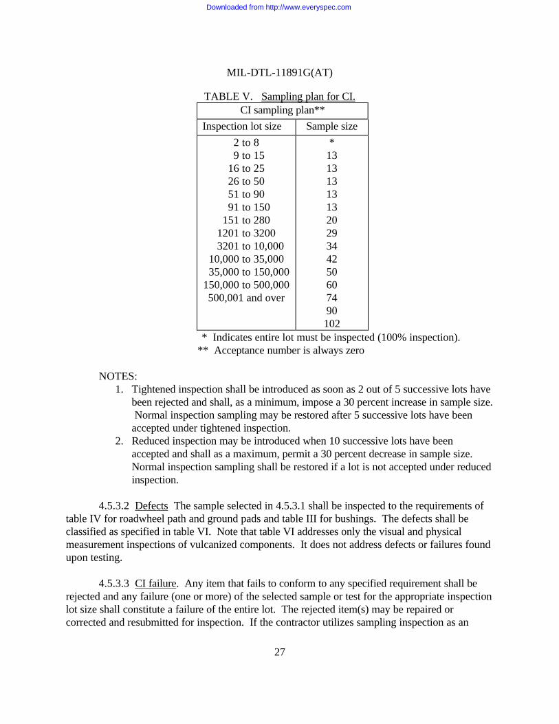
TABLE V. Sampling plan for CI.CI sampling plan**
Inspection lot size Sample size
2 to 8 9 to 1516 to 2526 to 5051 to 90
91 to 150151 to 280
1201 to 3200 3201 to 10,00010,000 to 35,000
35,000 to 150,000150,000 to 500,000500,001 and over
*13131313132029344250607490102
* Indicates entire lot must be inspected (100% inspection).** Acceptance number is always zero
NOTES:1. Tightened inspection shall be introduced as soon as 2 out of 5 successive lots have
been rejected and shall, as a minimum, impose a 30 percent increase in sample size. Normal inspection sampling may be restored after 5 successive lots have beenaccepted under tightened inspection.
2. Reduced inspection may be introduced when 10 successive lots have beenaccepted and shall as a maximum, permit a 30 percent decrease in sample size. Normal inspection sampling shall be restored if a lot is not accepted under reducedinspection.
4.5.3.2 Defects The sample selected in 4.5.3.1 shall be inspected to the requirements oftable IV for roadwheel path and ground pads and table III for bushings. The defects shall beclassified as specified in table VI. Note that table VI addresses only the visual and physicalmeasurement inspections of vulcanized components. It does not address defects or failures foundupon testing.
4.5.3.3 CI failure. Any item that fails to conform to any specified requirement shall berejected and any failure (one or more) of the selected sample or test for the appropriate inspectionlot size shall constitute a failure of the entire lot. The rejected item(s) may be repaired orcorrected and resubmitted for inspection. If the contractor utilizes sampling inspection as an
Downloaded from http://www.everyspec.com

MIL-DTL-11891G(AT)
28
element of his inspection system, rejected inspection lots may be resubmitted for acceptance if thecontractor performs 100 percent inspection on the lot for those characteristics which weredefective and resulted in rejection of the lot and removes all defective units or obtains procuringactivity approval to resample the lot due to the insignificance of the defects. Resubmitted lotsshall be kept separate from new lots and shall be clearly identified as resubmitted lots. Blemisheson rubber components which have not been listed in table VI and are primarily appearance orcosmetic conditions (poor markings, pitting of molds, minor surface contamination) should beresolved by manufacturers as these conditions arise.
TABLE VI. Classification of defects.
Classification DefectMethod ofinspection
Blisters A void or hole in article which causes protrusion onsurface when hot, may not show on surface when cold- unacceptable in bushings. Allowable tolerance 1/16inch max length/depth on pads and wheel-side rubber.Same as backflow or back-flash. Distortion at themold line in the form of wrinkles, folds, tears.
SIE 1/
Back-rinding Unacceptable on bushings. Allowable tolerance 1/16inch deep, 1/16 inch wide, 1/2 inch length along themold line.
SIE
Cracks Failure of rubber stock to knit together properly. Itmay be found in any part of the rubber surface and alsoat the rubber base next to the metal.
Visual
Chipped
Cuts/Tears
Folds
ForeignmaterialsWide flash
Rubber missing due to chipping, usually duringremoval from mold or during trimming. Unacceptableon bushings. Allowable tolerance 1/8 inch max indepth/ length, provided there is no cutting beyond thisdimension.A slit, nick, or gash caused primarily by trimmingof vulcanized components. Tear may be caused duringremoval of items from molds.A crease or pleat, usually appears as overlap of rubberon itself with a relatively weak cohesion.Any extraneous matter such as wood, paper, metal,dirt, etc. penetrating past the rubber surface.Thick spew-out rubber during moldings that resultsin dimensional noncompliance of the vulcanizedcomponent.
SIE
Visual
Visual
Visual
SIE
Downloaded from http://www.everyspec.com

MIL-DTL-11891G(AT)
29
TABLE VI. Classification of defects - Continued.
Classification DefectMethod ofinspection
Light/non-fill/air check
Insufficient material to fill mold, leaving voids or non-fill conditions on component. Trapped air, poorlyvented molds, excess mold lubricant can also cause thisdefect. Unacceptable on bushings. Allowabletolerance 1/16 inch max depth and 1/8 inch max length.
SIE
Separation Separation in the rubber or between the rubber andadhesives or rubber and metals.
Visual
Off-Register Uneven or misaligned molds causing non-conformityto dimensional requirements of the drawing.
SIE
Undercure Appears as tackiness, softness, porous, loginess, lowhardness or other inferior physical properties. Usuallycaused by improper cure conditions or defectiverubber.
SIE
Overcure Vulcanizing to the point that physical property(hardness, tensile strength, etc) requirements areimpaired.
SIE
Dimensionalnon-compliance
Molding that will result in concaveness, convexity orother dimensional irregularities of the components tomeet the dimensional requirements of the drawing orresult in adverse performance of the products.
SIE
1/ SIE = Standard Inspection Equipment
4.5.3.4 Packaging and packing.
4.5.3.4.1 Lot formation. A lot shall consist of all packs prepared for shipment inaccordance with one level (see 6.2), from an identifiable production period, from onemanufacturer, submitted at one time for acceptance.
4.5.3.4.2 Sampling for acceptance examination. Sampling for acceptance examinationshall be performed in accordance with table V.
4.5.3.4.3 Examination inspection for packaging and packing. Samples selected in4.5.3.4.2 shall be inspected as specified by the procuring activity (see 5.1 and 6.2).
4.5.3.4.4 Sample failure. Failure of the sample to pass any specified inspection may because for the Government to refuse to accept the lot until it has been proved to the satisfaction ofthe Government that the faults revealed have been corrected.
Downloaded from http://www.everyspec.com

MIL-DTL-11891G(AT)
30
4.6 Control tests.
4.6.1 Control test samples. Control test samples shall be selected in accordance with theschedule shown in table III for bushings and table IV for roadwheel path and ground pad material.
4.6.2 Control test failure. Any deficiency in any control test component shall bepresumed to be present in components subsequently produced after selection of the control testcomponent unless evidence satisfactory to the Procuring Activity is presented by the contractorthat such components are not similarly defective. Upon determination that said defects do exist,the Government reserves the right to refuse to accept further production until the contractordemonstrates that corrective action has been taken to eliminate the cause of such defects. Formaterial produced after the last successful control test or for material produced prior to controltest failure, the contractor shall provide evidence that the material produced met requirements. Evidence can be in the form of sampling inspection.
4.6.3 Additional specimens. In the event of failure of the first selected specimen to passthe test, two additional specimens shall be selected and both shall pass the same test. If these lasttwo specimens pass the test, then that control test is considered to be met. Failure of the firstspecimen to pass the test, or failure of either the second or third specimens to pass the test, will because for the Government to discontinue acceptance and to return units previously acceptedwhich can be identified with the lot corresponding to the failed sample.
4.7 Methods of inspection.
4.7.1 Bushings.
4.7.1.1 Specific gravity. This test shall be performed to the requirements of 3.3.3.2.During production, this test shall be performed as batches of unvulcanized rubber are finalized (allingredients have been added and mixed in the compound). Each batch of compound will beidentified and tested. The results from these tests will meet the tolerances established from dataacquired during qualification and the tolerances listed in table I.
4.7.1.2 Hardness. This test shall be performed to the requirements of 3.3.3.3. Duringproduction, one sample will be taken on unvulcanized and vulcanized rubber on a per shift basis.The results from these tests shall meet the tolerances established from data acquired duringqualification and the tolerances listed in table I.
4.7.1.3 Tensile strength. This test shall be performed to the requirements of 3.3.3.4.During production one unvulcanized sample will be taken right after mixing. The results fromthese tests will meet the tolerances established from data acquired during qualification and thetolerances listed in table I.
Downloaded from http://www.everyspec.com

MIL-DTL-11891G(AT)
31
4.7.1.4 Tensile strength (aged). This test shall be performed to meet the requirements of3.3.3.5. During production, one unvulcanized sample will be taken right after mixing on amonthly basis.
4.7.1.5 Ultimate elongation. This test shall be performed to the requirements of 3.3.3.4.During production, one unvulcanized sample will be taken on a per shift basis right after mixing.The results from these tests shall meet the tolerances established from data acquired duringqualification and the tolerances listed in table I.
4.7.1.6 Ultimate elongation (aged). This test shall be performed to the requirements of3.3.3.5. During production, one unvulcanized sample will be taken on a monthly basis right aftermixing.
4.7.1.7 Tensile stress (modulus). This test shall be performed to the requirements of3.3.3.4. During production, one unvulcanized sample will be taken right after mixing on a pershift basis. The results from these tests shall meet the tolerances established from data acquiredduring qualification and the tolerances listed in table I.
4.7.1.8 Thermogravimetric analysis. This test shall be performed to the requirements of3.3.3.6. During production this test shall be performed on one sample of unvulcanized rubber ona bi-monthly basis. The results will be compared to the established test results obtained atqualification.
4.7.1.9 Vulcanization using oscillating disk cure meter. This test will be performed tothe requirements of 3.3.3.7. The test shall be performed as batches of unvulcanized rubber arefinalized (all ingredients have been added and mixed in the compound). Each batch of compoundwill be identified and tested.
4.7.1.10 Adhesion. This test shall be performed to meet the requirements of 3.3.3.8.During production, the test shall be performed on one sample of vulcanized rubber per shift.
4.7.1.11 Compression set. Compression set shall be performed to the requirements of3.3.3.9. During production, the test shall be performed on unvulcanized rubber sampled at thefrequency of one sample monthly.
4.7.1.12 Brittleness point of flexible polymers. This test shall be performed to therequirements of 3.3.3.10. During production, the test shall be performed on unvulcanized rubbersampled at the frequency of one sample monthly.
Downloaded from http://www.everyspec.com
MIL-DTL-11891G(AT)
32
4.7.1.13 GC mass spec. This test shall be performed to the requirements of 3.3.3.11.During production, the test shall be performed on unvulcanized rubber sampled at the frequencyestablished by the Government. The results will be compared to the established test resultsobtained at qualification.
4.7.1.14 Bushing fill. To determine conformance to 3.5.4, the contractor shall test eachmold cavity as specified herein. Every time a mold is reworked, or a new mold is produced, eachcavity shall be tested. Prior to initiation of production, each mold shall have each bushing cavitytested for minimum and maximum fill by use of the approved compound in the followingprocedure:
a. Mold one set of bushing to pin or sleeve, without bond (do not use bonding agent)for minimum fill in accordance with 4.7.1.14.1, and maximum fill in accordancewith 4.7.1.14.2. Another set of bushings which shall be bonded may be used formaximum fill determination in accordance with 4.7.1.14.3 in lieu of 4.7.1.14.2. Record mold position of each bushing. Record the outside diameter of each pin orsleeve of the unbonded set in inches to three decimal places.
b. Ensure skin coating between or beyond rings and flash is not in excess of0.031 inch.
c. Record from track shoe drawing the following dimensions in inches:(1) Maximum and minimum diameter of bore in shoe body.(2) Average length of bore in shoe body. NOTE: On the boss and bushing sleeve
combination where the bushing sleeve is shorter than its mating boss, use thebushing sleeve length as the determining factor).
4.7.1.14.1 Minimum fill determination. Using the unbonded bushing, the followingprocedure shall be completed:
a. Slide bushing elastomer off pin or sleeve.b. Immerse elastomer in graduated cylinder of water. Water and bushing shall be at
the same temperature of 80 + 20°F. Record volume of water displaced in cubiccentimeters.
c. Apply data from drawings and recorded bushing sleeve diameter in the followingformula:
Vcc = 12.227 (Do2 - Di2)LWhere:
Do = maximum diameter of bore (inches)Di = recorded diameter of pin or sleeve (inches)L = average length of bore or sleeve (inches)Vcc = volume of cavity for bushing
Downloaded from http://www.everyspec.com
MIL-DTL-11891G(AT)
33
The constant 12.227 included factors for conversion of inches to centimeters andto reduce to 95% volume. The calculation for each cavity is to be accomplishedfor minimum fill by using the maximum diameter and average length.
d. The displaced volume recorded from 4.7.1.14.1b is to be compared to and beequal to or greater than the calculated volume of 4.7.1.14.1c.
4.7.1.14.2 Maximum fill determination (unbonded). Using the unbonded bushing, thefollowing procedure shall be completed:
a. Perform steps in 4.7.1.14.1a and 4.7.1.14.1b.b. Apply data from drawings and recorded sleeve diameters in the following formula:
Vmax = 13.515 (D min 2 -Di2 ) LD min = minimum diameter of bore (inches)Di = recorded diameter of pin or sleeveL = average length of bore or sleeve (inches)Vmax = volume of cavity for bushing in cubic centimeters. The constant 13.515 includes factors for conversion of inches to centimeters andto increase to 105 percent volume.
c. The displaced volume recorded from 4.7.1.14.1b is to be compared to and beequal to or equal to or less than the calculated volumes of 4.7.1.14.1b.
4.7.1.14.3 Maximum fill determination (bonded). Using the bonded bushing, thefollowing procedure shall be completed:
a. Provide one or more tubes, either steel or plastic, with a minimum bore diameterand the length equal to 105 percent of the average bore length of the shoe body inwhich the bushing is to be used.
b. Insert the bonded bushing in the tube.c. One bushing from each cavity shall be tested.
4.7.1.15 Concentricity. Concentricity shall be measured with a depth gage or steel rule todetermine conformance with 3.5.4.1. Samples shall be taken in accordance with table V.
4.7.2 Track roadwheel path and ground pad.
4.7.2.1 Specific gravity. This test shall be performed to the requirements of 3.3.4.1.During production, the test shall be performed on unvulcanized rubber sampled at the frequencyof one per batch at the final mixing. The results from these tests shall meet the tolerancesestablished from data acquired during qualification and the tolerances listed in table II.
Downloaded from http://www.everyspec.com
MIL-DTL-11891G(AT)
34
4.7.2.2 Hardness. This test shall be performed to the requirements of 3.3.4.2. Duringproduction, one sample per shift shall be taken from the unvulcanized rubber. In addition, onetest shall be performed per shift on a finished component. The results from these tests shall meetthe tolerances established from data acquired during qualification, and the tolerances listed intable II.
4.7.2.3 Tensile strength. This test shall be performed to the requirements of 3.3.4.3.During production, one sample per shift shall be taken on unvulcanized rubber after final mixing.In addition, one sample per week shall be taken from the finished component (replaceable andintegral pads only). The results from these tests shall meet the tolerances established from dataacquired during qualification and the tolerances listed in table II.
4.7.2.4 Tensile strength (aged). This test shall be performed to the requirements of3.3.4.4. During production, one sample per month shall be taken from the finished component(replaceable and integral pads only). One sample per month shall be taken from the unvulcanizedrubber (roadwheel path only).
4.7.2.5 Ultimate elongation. This test shall be performed to the requirements of 3.3.4.3.During production, one sample per shift shall be taken on unvulcanized rubber after final mixing.In addition, one sample per week shall be taken from the finished component(replaceable andintegral pads only). The results from these tests shall meet the tolerances established from dataacquired during qualification, and the tolerances listed in table II.
4.7.2.6 Ultimate elongation (aged). This test shall be performed to the requirements of3.3.4.4. During production, one sample per month shall be taken from the finished component(replaceable and integral pads only). One sample per month shall be taken from the unvulcanizedrubber (roadwheel path only).
4.7.2.7 Tensile stress (modulus). This test shall be performed to the requirements of3.3.4.3. During production, one sample per shift shall be taken on the unvulcanized rubber afterfinal mixing. In addition, one sample per week shall be taken from the finished component(replaceable and integral pads only). The results from these tests will meet the tolerancesestablished from data acquired during qualification, and the tolerances listed in table II.
4.7.2.8 Thermogravimetric analysis. This test shall be performed to the requirements of3.3.4.5. During production, this test shall be performed on unvulcanized rubber sampled at thefrequency of one sample bi-monthly.
4.7.2.9 Oscillating disk cure meter. This test shall be performed to the requirements of3.3.4.6. During production, this test shall be performed on unvulcanized rubber sampled at thefrequency of one sample per batch.
Downloaded from http://www.everyspec.com

MIL-DTL-11891G(AT)
35
4.7.2.10 Adhesion. This test shall be performed to the requirements of 3.3.4.7. Duringproduction, one sample per shift shall be taken on vulcanized rubber.
4.7.2.11 Ozone resistance. This test shall be performed at the rate of one sample permonth in accordance with the requirements of 3.3.4.8 or 3.3.4.9.
4.7.2.12 Brittleness point of flexible polymers. This test shall be performed to therequirements of 3.3.4.10. During production, one sample shall be taken monthly fromunvulcanized final mixed compounds.
4.7.2.13 GC mass spec. This test shall be performed to the requirements of 3.3.4.11.During production, samples shall be taken as required by the Government.
4.7.2.14 Blowout test. This test shall be performed to the requirements of 3.3.4.12.Fifteen (15) track block samples of each compound for each configuration being submitted forqualification shall be required. Up to twelve (12) track block samples may be required by theGovernment during a production contract for the T107 track systems.
5. PACKAGING
5.1 Packaging. For acquisition purposes, the packaging requirements shall be as specifiedin the contract or order (see 6.2). When actual packaging of materiel is to be performed by DoDpersonnel, these personnel need to contact the responsible packaging activity to ascertain requisitepackaging requirements. Packaging requirements are maintained by the Inventory Control Point’spackaging activity within the Military Department or Defense Agency, or within the MilitaryDepartment’s System Command. Packaging data retrieval is available from the managing MilitaryDepartment’s or Defense Agency’s automated packaging files, CD-ROM products, or bycontacting the responsible packaging activity.
6. NOTES
(This section contains information of a general or explanatory nature that may be helpful,but is not mandatory.)
6.1 Intended use. The elastomerized track shoe assemblies, track shoe bushings, andtrack shoe pads covered by this specification and track shoe sets assembled therefrom areintended for use in track systems on tracked military vehicles. These track shoes are militaryunique because they are used on tracked military vehicles and have a specific formulation whichdoes not have a commercial application.
Downloaded from http://www.everyspec.com
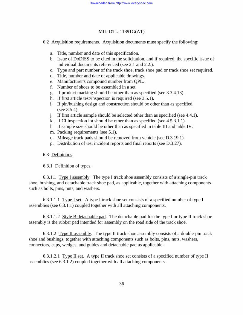
MIL-DTL-11891G(AT)
36
6.2 Acquisition requirements. Acquisition documents must specify the following:
a. Title, number and date of this specification.b. Issue of DoDISS to be cited in the solicitation, and if required, the specific issue of
individual documents referenced (see 2.1 and 2.2.).c. Type and part number of the track shoe, track shoe pad or track shoe set required.d. Title, number and date of applicable drawings.e. Manufacturer's compound number from QPL.f. Number of shoes to be assembled in a set.g. If product marking should be other than as specified (see 3.3.4.13).h. If first article test/inspection is required (see 3.5.1).i. If pin/bushing design and construction should be other than as specified
(see 3.5.4).j. If first article sample should be selected other than as specified (see 4.4.1).k. If CI inspection lot should be other than as specified (see 4.5.3.1.1).l. If sample size should be other than as specified in table III and table IV.m. Packing requirements (see 5.1).o. Mileage track pads should be removed from vehicle (see D.3.19.1).p. Distribution of test incident reports and final reports (see D.3.27).
6.3 Definitions.
6.3.1 Definition of types.
6.3.1.1 Type I assembly. The type I track shoe assembly consists of a single-pin trackshoe, bushing, and detachable track shoe pad, as applicable, together with attaching componentssuch as bolts, pins, nuts, and washers.
6.3.1.1.1 Type I set. A type I track shoe set consists of a specified number of type Iassemblies (see 6.3.1.1) coupled together with all attaching components.
6.3.1.1.2 Style B detachable pad. The detachable pad for the type I or type II track shoeassembly is the rubber pad intended for assembly on the road side of the track shoe.
6.3.1.2 Type II assembly. The type II track shoe assembly consists of a double-pin trackshoe and bushings, together with attaching components such as bolts, pins, nuts, washers,connectors, caps, wedges, and guides and detachable pad as applicable.
6.3.1.2.1 Type II set. A type II track shoe set consists of a specified number of type IIassemblies (see 6.3.1.2) coupled together with all attaching components.
Downloaded from http://www.everyspec.com

MIL-DTL-11891G(AT)
37
6.3.1.3 Style. A style A track shoe does not have a detachable pad and the style Bincorporates detachable pad.
6.3.2 Definition of defects.
a. Blister. Void or hole in item; causes protrusion on surface when hot; may notshow on surface when cold; may be covered or open.
b. Crack. Failure of material to join together properly.c. Nonfill. Air checks; depressions due to trapping of air at corners and edges.d. Light stock. Insufficient material to fill mold.e. Fold. Lapping or doubling of material resulting in crease or pleat.f. Backrinding. Distortion at the mold line, usually in the form of wrinkles, folds,
tears, or indentations.g. Flash rubber. Spew-out of material at mold parting line.h. Porosity. Presence of numerous minute voids in cured material.i. Non-knit. Weakness where rubber flows together during molding.
6.3.3 Definitions for process control.
a. Process parameter. Process parameters are associated with the process used forthe manufacture of material. Typical parameters include; time, temperature, feedrate, pressure, etc.
b. Product characteristic. Product characteristics include: hardness, length,diameter, specific gravity, tensile strength, concentricity, etc.
c. Control techniques. Control techniques are used for either process or productpurposes as applicable. Examples of control techniques include: StatisticalProcess Control, first and last piece verifications, temperature monitoring deviceswith warnings or auto processing stops, detection inspections, etc.
d. Analysis methods. Analysis methods are used for the identification of processparameters and product characteristics. Typical analysis methods include: Designof Experiments, Regression Analysis, Failure Modes Effect Analysis, QualityFunctional Deployment, etc.
e. Process fingerprint. Documented and detailed information that thoroughlydescribes the entire process used to produce the final product. This documentationincludes: test, process parameter and product characteristic target values andtolerances, in-process materials and process settings, and all other important andrelevant information.
6.3.3.1 Preparing activity. The military activity responsible for the preparation andmaintenance of this document and the associated Qualified Products List. The preparing activityis responsible for qualification, and is the qualifying activity and authority.
Downloaded from http://www.everyspec.com

MIL-DTL-11891G(AT)
38
6.3.4 Definitions for rubber products. Use ASTM D1566 for rubber terminology anddefinitions.
6.4 Code numbers. Manufacturer's code numbers should conform to those listed in“Federal Supply Code for Manufacturers Cataloging Handbook”, identified as “H-4.1, H-4.2, andSupplement”.
6.5 Illustrations. The illustrations shown herein (see figures 1 through 4) are relevant tothe preparation of rubber specimens for testing purposes; they are not intended to represent shoeor pad designs.
6.6 Testing agencies. Contractors may use their own or any other testing agency forperforming the tests required under this specification providing it is acceptable to the qualifyingactivity for qualification tests or the contracting officer for any other testing. On-vehicle testingwill be performed by the Government.
6.6.1 Subject term (key word) listing.
MilitaryTrackedVehicles
6.7 Qualification. With respect to products requiring qualification, awards will be madeonly for products which are, at the time of award of contract, qualified for inclusion in QualifiedProducts List QPL No. 11891 whether or not such products have actually been so listed by thatdate. The attention of the contractors is called to these requirements, and manufacturersare urged to arrange to have the products that they propose to offer to the Federal Governmenttested for qualification in order that they may be eligible to be awarded contracts or purchaseorders for the products covered by this specification. Information pertaining to qualification ofproducts may be obtained from the U.S. Army Tank-automotive and Armaments Command,ATTN: AMSTA-TR-E/BLUE, Warren, MI 48397-5000.
Downloaded from http://www.everyspec.com

MIL-DTL-11891G(AT)
39
6.7.1 Extension of qualification. Elastomer compounds used in track models that havebeen tested and met all qualification requirements of this specification may be extendedqualification for use in similar track shoe models as listed.
Track model tested Qualification extended to:
Track assembly T107 T107, T138, T144, and alltype II, style A tracks.
Track assembly T154 T154, T164, T150, T130E1,T136, T132E1, and allreplaceable pad tracks exceptT158/T158LL. T142 with FirstArticle Blow-out Test required.T157I with First Article orQualification Test for pad.
Track pads T154 All style B tracks exceptT157I, T158/Tl58LL
Bradley track pad T157I NoneBushings T130El All track systems except
T158/TI58LL
6.8 Track cross reference. The following track shoe assemblies have been assigned modelnumbers for easy reference:
Army Drawing no. Nomenclature Model12306600 Track, Double Pin T15012268550 Track, Double Pin T15412352500 Track, Double Pin T1648705914 Track, Double Pin T10710892811 Track, Double Pin T14410934639 Track, Single Pin T132El10948405 Track, Single Pin T13810954051 Track, Double Pin T13611645125 Track, Double Pin T14211677988 Track, Single Pin T130El12359466 Track, Single Pin T157I
6.9 Changes from previous issue. Marginal notations are not used in this revision toidentify changes with respect to the previous issue due to the extent of the changes.
Downloaded from http://www.everyspec.com

MIL-DTL-11891G(AT)
40
6.10 First article. When first article inspection is required, the contracting officer shouldprovide specific guidance to offerors whether the item(s) should be a preproduction sample, a firstarticle sample, a first production item, a sample selected from the first production items, astandard production item from the contractor’s current inventory (see 3.5.1), and the number ofitems to be tested as specified in 4.4.1. The contracting officer should also include specificinstructions in acquisition documents regarding arrangements for examinations, approval of firstarticle test results, and disposition of first articles. Invitations for bids should provide that theGovernment reserves the right to waive the requirement for samples for first article inspection tothose bidders offering a product which has been previously acquired or tested by the Government,and that bidders offering such products, who wish to rely on such production or test, must furnishevidence with the bid that prior Government approval is presently appropriate for the pendingcontract. Bidders should not submit alternate bids unless specifically requested to do so in thesolicitation.
NOTICE: When Government drawings, specifications, or other data are used for any purposeother than in connection with a definitely related Government procurement operation, the UnitedStates Government thereby incurs no responsibility nor any obligation whatsoever; and the factthat the Government may have formulated, finished, or in any way supplied the said drawings,specifications, or other data is not to be regarded by implication or otherwise as in any mannerlicensing the holder or any other person or corporation, or conveying any rights or permission tomanufacture, use, or sell any patented invention that may in any way be related thereto.
Downloaded from http://www.everyspec.com
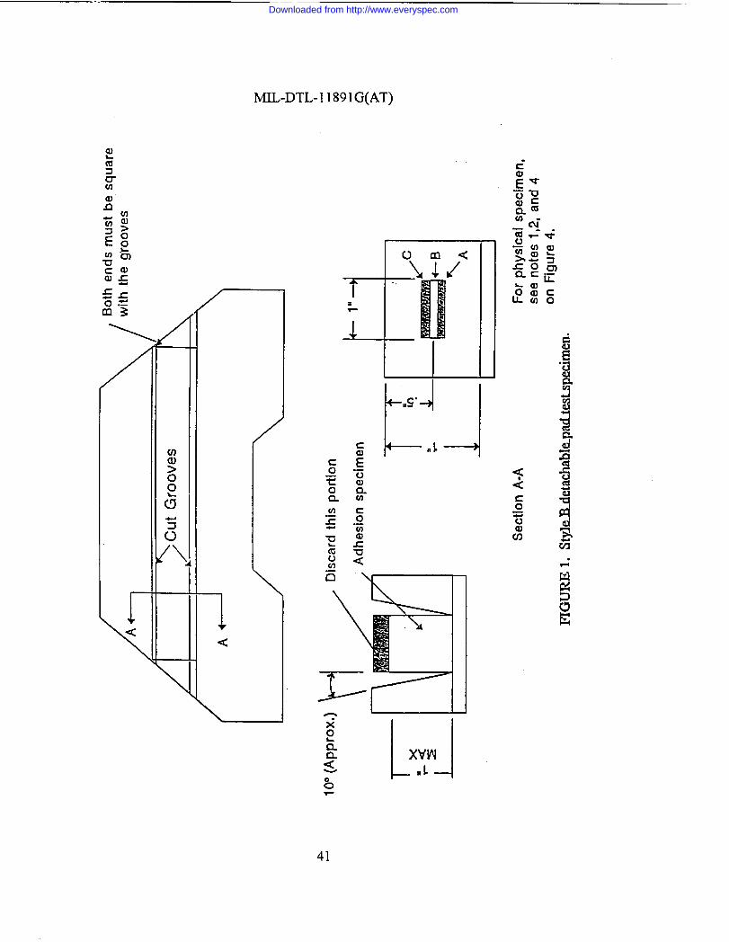
MIL-DTL-1 1891G(AT)
/—
—
—
\
1<
/
\
41
Downloaded from http://www.everyspec.com
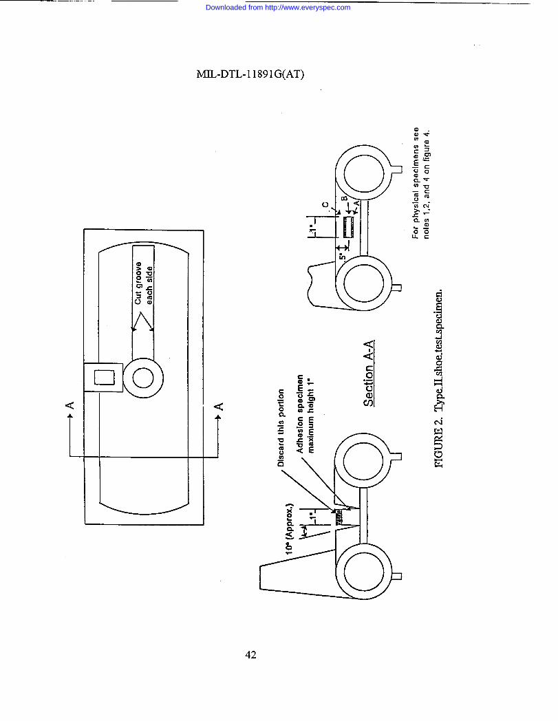
<A
1
MIL-DTL-1 1891G(AT)
42
Downloaded from http://www.everyspec.com

MIL-DTL-1 1891G(AT)
.
.
1+
43
Downloaded from http://www.everyspec.com
MIL-DTL-11891G(AT)
.
0 #2- ---v4
.
44
Downloaded from http://www.everyspec.com

MIL-DTL-1 1891G(AT)
. .
Tcack ShoeRubber Undec
-
Ii
SKTIOHAL VICd
ofbad
FIGURE5. Blow-cmt machine.
45
Downloaded from http://www.everyspec.com

MIL-DTL-11891G(AT)
A+
>CUICMOOVCS
A+
10°(Approx.}‘f-l
Discard Mb portion*l-
Adhesion specimen % 2 /c
L J + “ ‘
,. ,.B
~“ a
4‘A
Max
section A-A For phydcal 3pcchncn,seenotes12 and4onFlgum4.
FIGURE 6. T1571 detachable Dadtest suecimen.
46
Downloaded from http://www.everyspec.com
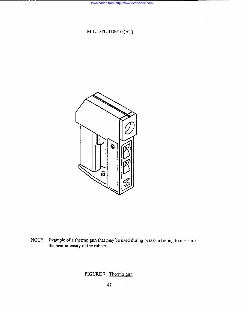
MIL-DTL-1 1891G(AT)
\
NOTE: Example of a thermo gun that maybe used during break-in testing to measurethe heat intensity of the rubber.
FIGURE 7. Thormo gun.
47
Downloaded from http://www.everyspec.com
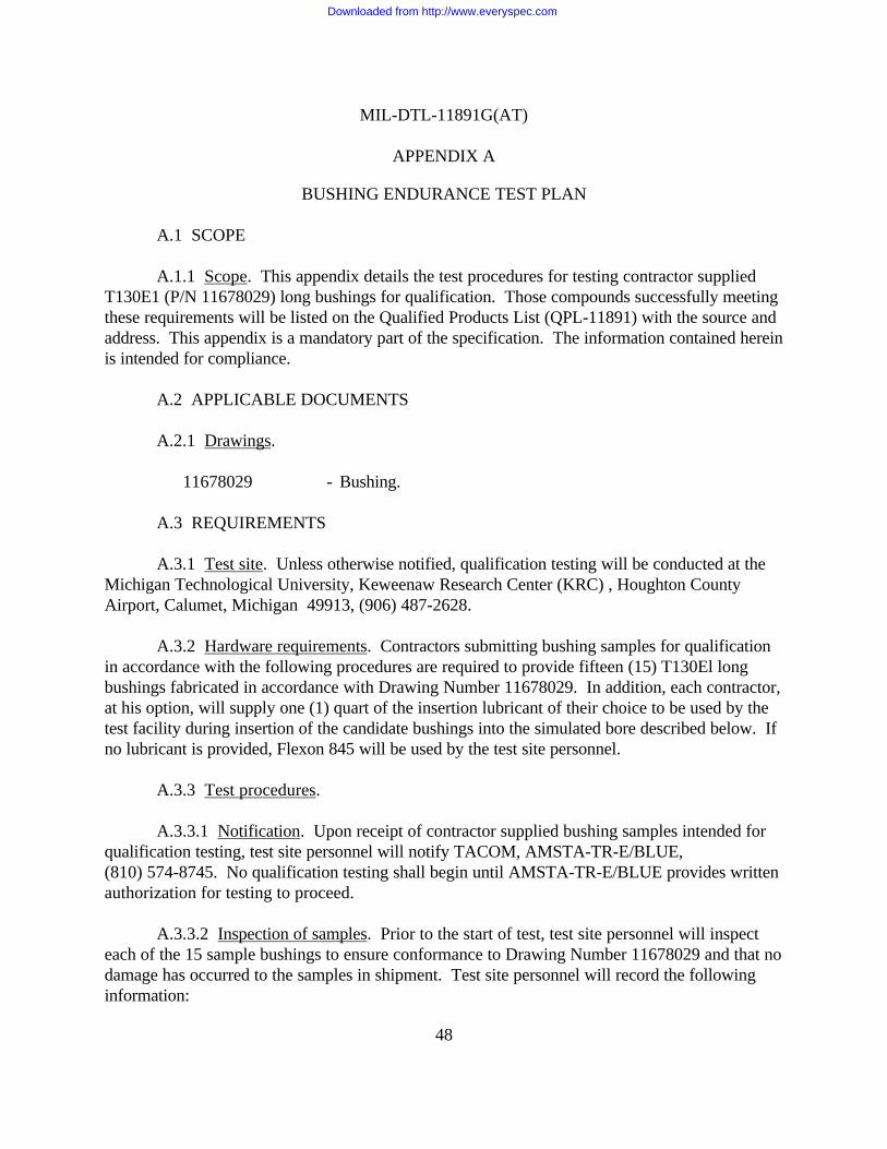
MIL-DTL-11891G(AT)
APPENDIX A
48
BUSHING ENDURANCE TEST PLAN
A.1 SCOPE
A.1.1 Scope. This appendix details the test procedures for testing contractor suppliedT130E1 (P/N 11678029) long bushings for qualification. Those compounds successfully meetingthese requirements will be listed on the Qualified Products List (QPL-11891) with the source andaddress. This appendix is a mandatory part of the specification. The information contained hereinis intended for compliance.
A.2 APPLICABLE DOCUMENTS
A.2.1 Drawings.
11678029 - Bushing.
A.3 REQUIREMENTS
A.3.1 Test site. Unless otherwise notified, qualification testing will be conducted at theMichigan Technological University, Keweenaw Research Center (KRC) , Houghton CountyAirport, Calumet, Michigan 49913, (906) 487-2628.
A.3.2 Hardware requirements. Contractors submitting bushing samples for qualificationin accordance with the following procedures are required to provide fifteen (15) T130El longbushings fabricated in accordance with Drawing Number 11678029. In addition, each contractor,at his option, will supply one (1) quart of the insertion lubricant of their choice to be used by thetest facility during insertion of the candidate bushings into the simulated bore described below. Ifno lubricant is provided, Flexon 845 will be used by the test site personnel.
A.3.3 Test procedures.
A.3.3.1 Notification. Upon receipt of contractor supplied bushing samples intended forqualification testing, test site personnel will notify TACOM, AMSTA-TR-E/BLUE,(810) 574-8745. No qualification testing shall begin until AMSTA-TR-E/BLUE provides writtenauthorization for testing to proceed.
A.3.3.2 Inspection of samples. Prior to the start of test, test site personnel will inspecteach of the 15 sample bushings to ensure conformance to Drawing Number 11678029 and that nodamage has occurred to the samples in shipment. Test site personnel will record the followinginformation:
Downloaded from http://www.everyspec.com

MIL-DTL-11891G(AT)
APPENDIX A
49
a. Date received.b. Source address and code or compound number.c. Quantity of bushings.d. Conformance to Drawing No. 11678029.e. Comments regarding bushing condition.
NOTE: If any nonconformance or unusual condition of the bushings is noted by test sitepersonnel, the information shall be provided to TACOM, AMSTA-TR-E/BLUE,requesting disposition of the test samples.
A.3.3.3 Bushing sample insertion. Following a determination that all bushing samplesmeet the requirements established in A.3.3.2, test site personnel shall select and insert nine (9)bushings into simulated bores using the lubricant provided by the contractor or Flexon 845. Insertion shall be accomplished using the MTS 321 machine or equivalent.
A.3.3.4 Bushing sample aging. Following insertion, the nine bushing samples shall beaged for a minimum of 96 hours at an ambient room temperature of 75°F + 10°F.
A.3.3.5 Thermogravimetric analysis. Test site personnel shall select one (1) bushingsample from the remaining six (6) samples to be submitted to an independent laboratory capableof conducting thermogravimetric analysis (TGA). The results of the TGA must be closelysafeguarded and shall be provided with the results of the bushing endurance test for futurereference.
A.3.3.6 Bushing test machines. Following the 96 hour aging, the simulated bores shall beplaced into the bushing test machine(s). Three test machines are to be used if possible, equallydistributing the qualification samples (3 on each machine). The machine(s) will be calibrated andzeroed prior to test initiation.
A.3.3.7 Load profile. The load profile and phase angle relationship of each test machineshall be checked within the first hour of the initial bushing test, to ensure conformance to figures 1and 2 (attached).
A.3.3.8 Cyclic compression. Cyclic compression load shall be from 0 to 5200 poundsminimum at a frequency of 64 cycles per minute (cpm) +1 cpm. To ensure conformance to the5200 pound minimum, the test machine shall be set to provide 5300 pounds of compression load.
Downloaded from http://www.everyspec.com

MIL-DTL-11891G(AT)
APPENDIX A
50
A.3.3.9 Cyclic torsional deflection load. Simultaneous cyclic torsional deflection loadshall be from +15° to -15° (+l°) at a frequency of 256 cpm +4 cpm (see figure 9). Cyclic torsionaldeflection load frequency shall be maintained at four (4) times the cyclic compression loadfrequency by positive mechanical means.
A.3.3.10 Testing duration. Testing will be continuous (24 hours per day) until bushingfailure, defined by the deflection exceeding 0.144 inches (0.145 inches of deflection). Radial load,deflection, ambient temperature, bushing temperature, number of cycles, and time shall becontinuously monitored and recorded on a floppy disk using a Daytronic data acquisition system(or equivalent) for future reference as required. A one-time lapse of up to 30 minutes from therequirement of continuous operation of the test machine is permitted.
A.3.3.11 Test machine failure. In the event of a test machine failure, KRC shall discardthe bushing undergoing the endurance test and any data pertaining to it, and will randomly select anew bushing specimen for testing.
A.3.3.12 Qualification requirements. Qualification requirements are determined byeliminating the highest bushing test cycle result and averaging the remaining eight (8) bushing testcycles. The average shall be a minimum of 130 000 compression load cycles. No single bushing ofthe nine (9) tested shall be less than 110 000 cycles. If, at any time during the test, a test samplefails to attain the minimum 110 000 cycles, KRC shall notify TACOM, AMSTA-TR-E/BLUE(810) 574-8745 for disposition and direction.
A.3.3.13 Test completion. Following completion of the test, a report containing all testdata shall be provided to TACOM, AMSTA-TR-MTT and AMSTA-TR-E/BLUE. This report shallalso include the results of the thermogravimetric analysis. All test information and reports will bereleased by TACOM personnel only. KRC personnel will not release any test information tomanufacturers.
A.3.3.14 Sample disposition. All samples shall be retained by the test site until receipt ofofficial Government approval to release the samples to the contractor. All remaining samplesshall then be returned to the contractor supplying parts for qualification.
A.3.4 Monitoring and certification. The test shall be monitored and results certified bythe local Government Quality Assurance Representative (QAR) . Monitoring will be conducted toensure proper machine calibration and that the test is conducted in accordance with theestablished procedures. At a minimum, the QAR will visit KRC at the beginning of the test of acontractor's supplied bushings (at the installation of the first 3 bushings) and near the mid-point ofthe test (test initiation of bushing # 5). At the conclusion of all bushing tests, the QAR will make
Downloaded from http://www.everyspec.com
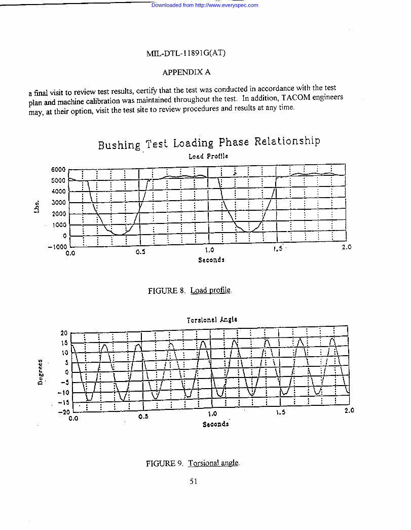
MJL-DTL-1 1891G(AT)
APPENDIX A
a final visit to review test results, certify that the test was conducted in accordance with the testplan and machine calibration was maintained throughout the test. In addition, TACOM engineersmay, at their option, visit the test site to review procedures and results at any time.
Bushing Test Loading Phase RelationshipLoad Prot!le
6000c : : . : : : : : : :.: :. . . .:, ... . # :
>: : :
::. . .5000
. . .: :.. .
.2~
. . . .
:
:
as 1.0 1*5< 2.00,0
FIGURE 8. Load t)rofile.
seconds
FIGURE 9. Torsional an.szle.
51
Downloaded from http://www.everyspec.com
MIL-DTL-11891G(AT)
APPENDIX B
52
T154 TRACK ON-VEHICLE TEST PLAN
B.1 SCOPE
B.1.1 Scope. This appendix defines a set of instructions and requirements to be used forconducting all replaceable pad track vehicle qualification tests. Although this appendix is specificin nature, the Preparing Activity may amend this appendix with a more detailed set of instructionsto meet the needs of the particular test. The requirements of this appendix are not to be changedwithout prior permission from the Preparing Activity. This appendix is a mandatory part of thisspecification. The information contained herein is intended for compliance.
B.2 APPLICABLE DOCUMENTS
B.2.1 Drawings.
12268550 - T-154 Track Shoe Assembly.12268551 - End Connector.12268552 - Link Assembly.12268557 - Molded Pad.12268561 - Nut, Plain.12268563 - Screw, Cap.
B.3 REQUIREMENTS
B.3.1 Test program review. A start of test meeting will be held at the test site on a dateand time to be established by the Preparing Activity. Any additional review meetings shall bescheduled only if considered necessary by the Preparing Activity.
B.3.2 Test site access. Access to the test site will be required by Government personnelon a continuous basis to conduct their test responsibilities. Contractor personnel shall not beallowed test site access without specific approval from the Preparing Activity.
B.3.3 Test program scope. This test will be accomplished by assembling themanufacturer's T154 track samples on an M-109 series vehicle and operated to the requirementsof this appendix.
B.3.4 T154 track design characteristics. The T154 track is a double-pin track with areplaceable track shoe pad. See figure 10 for a T154 track illustration with an associated partslisting.
Downloaded from http://www.everyspec.com

MIL-DTL-11891G(AT)
APPENDIX B
53
B.3.5 Test course. The test course to be used for conducting all on-vehicle qualificationtests will be selected by the Preparing Activity. The preferred course is located at the U.S. ArmyProving Ground (YPG), Yuma, Arizona. Yuma has been traditionally selected for on-vehicletrack testing because of climate, course, and test result consistency. The following standard tracklaying vehicle (tank and other tracked vehicles) test courses at YPG are designated for testingtrack for this specification.
a. Paved course. The dynamometer course is a 2-mile, smooth, near-level(0.8 percent grade) 30-foot wide roadway with 500-foot radius turnarounds ateach end, surfaced with a high strength asphalt. The course is located at anelevation of approximately 470 feet above sea level and is staked at 0.1-mileintervals throughout its length with accurately surveyed distance markers.
b. Gravel course. The tank gravel course is a 3.6-mile compacted and graded gravelcourse and is for testing track laying vehicles under conditions simulating asecondary gravel road. The course consists of short straight sections and curves ofvarying radii with many moderate and sharp turns.
c. Hilly cross-country course. The tank hilly cross-country B course is 2.7 miles longand has short steep grades (35 percent) with a greater proportion of slopes lessthan 20 percent. This course has surfaces varying from sand and gravel to exposedbedrock. The loose gravel, sharp stones and rocks present a severe cutting andabrasion problem for tracks and roadwheels.
d. Level-cross country course. The tank level cross-country course traverses areas oflevel, sandy terrain with many bumps that provide a severe test of track layingvehicles. The dust conditions are typical of cross-country operation on dry soil. One lap is 6.7 miles.
B.3.6 Operational mode summary. The operational mode summary for the test shallconsist of 25% paved (concrete, asphalt, or macadam); 50% on gravel composed mostly of smallstones; and 25% on cross-country (equal amount of hilly and level). During the test, the vehicleshall not traverse more than 50 continuous miles over any single type of terrain. Vehicle directionaround the test courses shall be changed periodically to assure approximately equal clockwise andcounterclockwise test operation.
B.3.6.1 Climatological conditions. In order to expose the track test samples to themaximum “hot” weather conditions, vehicle road testing shall be scheduled to start no earlier than1 March and no later than 1 September of the same calendar year.
Downloaded from http://www.everyspec.com

MIL-DTL-11891G(AT)
APPENDIX B
54
B.3.7 Track delivery and storage. Track shoe/pad samples are to be delivered to the testsite by a date specified by the Preparing Activity. Adequate time must be allowed for test sitepersonnel to inspect, mark, and install the hardware so as not to impact the projected test startdate. A secured area must be made available during and after the test for each of the trackshoe/pad samples. The samples received will be placed in a shaded area that prevents directsunlight from shining on the track pads during storage and assembly operations. The reduction ofvariables such as solar heating of the pads in a stack while other are shaded and, therefore, cooleris mandatory. Any condition that might influence the relative performance of the track shoes/padsare to be held as uniform as possible.
B.3.8 Contractor hardware requirements. For the qualification road test, the contractortest sample shall consist of 74 complete T154 track shoe assemblies (see B.3.11 for strandconfiguration). In addition, the following spare hardware shall be required: (a) 86 completeT154 track shoe assemblies, to include all pads and connecting components. (b) 70 track shoepad assemblies (to include pad nut P/N 12268561).
B.3.8.1 Sample size. For a contractor attempting qualification of T154 pad assembliesonly, the sample size shall be 74 pads. In addition the contractor shall be required to provide 76complete spare pad assemblies to include the pad nut.
B.3.9 Initial inspection/preparation for test. The test site shall perform a receivinginspection of the M109 series vehicle(s) to be used for the test. The basic test vehicle(s) will bevisually and functionally checked with specific attention given to suspension, electrical systems,hydraulic systems, and automotive controls and accessories. Any damage or improper operationwill be repaired/corrected to ensure the vehicle(s) will be capable of meeting the test requirementsdefined by this appendix.
B.3.9.1 Inspection of track samples. Contractor supplied track qualification samples willbe inspected to ensure no physical damage has occurred in shipment, that the required number ofsamples and spares have been provided and that all components are properly identified.
B.3.10 Track identification. To aid in failure and part life tracking, all track shoes,including spares, shall be identified to a manufacturer by permanent sequential number/lettercodes applied to the metal portion of the shoe body. The test site shall apply the number/lettercodes to the test track shoes prior to vehicle installation.
B.3.10.1 Track assembly marking. All 160 contractor supplied track assemblies shall bestamped with a lead designator alpha character only, prior to track break-in (see B.3.17). Following break-in, any failed shoes shall be removed and the remaining shoes shall besequentially numbered. The track shoes shall be marked on both the inboard and outboard faces,
Downloaded from http://www.everyspec.com

MIL-DTL-11891G(AT)
APPENDIX B
55
in the recessed area between the track pins as illustrated in figure 11. An example of the codingsystem to be used is as follows: X0l, X02.... X160 (X for Contractor ABC and 1, 2, 3, etc. fornumeric shoe designation). The test site shall contact the Preparing Activity to request a codeletter identification upon receipt of a contractors supplied hardware.
B.3.10.2 Serial pad marking. Serial marking of pads may be required as specified by thePreparing Activity.
B.3.10.3 Pad installation and coding. Pads supplied for pad qualification only will beinstalled on Government furnished T154 track assemblies. The Government furnished track shallbe coded using the alpha code letter “G” followed by a contractor code letter corresponding tothe contractor furnishing the pads for qualification. The code letters shall be located as illustratedin figure 11.
B.3.11 Track shoe installation pattern. Each vehicle shall have the capacity to test twocontractors supplied samples. Each strand will consist of 39 assemblies from each of twocontractors and two Government furnished T154 assemblies. The Government furnishedassemblies will be removed, as required, to maintain track tension. Two transition shoes (one ofeach of two different contractors) at the connection points will not be considered in thequalification sample, making the qualification sample size 37 in each of two strands. The trackshoe installation pattern on the M109 series vehicle shall be provided to the test site by thePreparing Activity. Track installation shall be accomplished in accordance with the appropriatetechnical manuals.
B.3.12 Load condition. For the test, the weight of the M109 vehicle shall be adjusted to58 500 pounds, plus or minus 400 pounds. The load shall be distributed approximately equal oneach track when on a level surface.
B.3.13 Pivoting of vehicles. Pivot steering of vehicles during break-in and qualificationtesting is to be kept at a minimum. Sudden braking action shall also be avoided to the extentpossible.
B.3.14 Track tension adjustments. All tension adjustments shall be made prior to the startof the test as well as during test operations. As a minimum, track tension shall be checked on adaily basis. These adjustments shall be made after inspection faults have been corrected. Tracktension requirements can be found in the latest technical manuals for the M109 series vehicle. NOTE: Low track tension will cause thrown tracks, broken or bent pins, and broken
Downloaded from http://www.everyspec.com
MIL-DTL-11891G(AT)
APPENDIX B
56
end connectors and center guides. High track tension shall also be avoided. Track pins will breakand tracks will be thrown, the track adjuster or grease gun shall be kept from contacting the trackshoe rubber parts. Any grease or oil accidentally contacting the shoe shall be immediately wipedoff.
B.3.15 Track component replacement. Track shoe assembly replacements are requiredbased on meeting the failure criteria for any number of component parts (bushing, roadwheel pathrubber, center guide, or shoe body damage). The component failure criteria is detailed in the tableVII. The individual shoe replacements shall be made in the same strand location as the respectivefailed shoes. In addition, if the pads meet the acceptance criteria, the pads from the original trackshoe shall be reinstalled on the replacement shoe.
B.3.15.1 Hardware torque. When track shoes, pads or end connectors are replaced, thenew hardware must be torqued checked after the first 50 miles of operation.
B.3.16 Torque values. All T154 track hardware shall be torqued to the following valuesand in accordance with proper maintenance procedures:
Clamp type end connector 400 +20 wet lb-ft.Track shoe pad nuts 110 - 150 dry lb-ft.
B.3.17 Break-In run. The purpose of the break-in run procedure is to simulate the naturalaging process afforded production/spare track during normal transit/storage periods before actualvehicle use. All test samples (to include spares and all pads provided for qualification) shall bebroken in prior to the road test by having the vehicle on which they are installed, continuouslyoperated for 45 miles on a paved road (concrete, asphalt, or macadam) as follows:
Division of Speed DistanceBreak-in run m.p.h. (max) miles (min)
a 10 15b 15 15c 20 15
B.3.17.1 Vehicle operation. The vehicle shall be operated in both directions for one-halfof the total vehicle distance.
B.3.17.2 Track cooling. During the break-in run, the track shall be allowed to coolbetween each phase of testing. This cooling of the track can be verified through one of thefollowing two procedures.
Downloaded from http://www.everyspec.com

MIL-DTL-11891G(AT)
APPENDIX B
57
B.3.17.2.1 Track roadwheel path surface. The track roadwheel path surface shall becooled to the point where the palm of the hand can be held to the surface backing in excess of10 seconds.
B.3.17.2.2 Cool down. Cool down between speed changes shall require the use of adevice used to measure the temperature of the rubber pads (see figure 7 for a diagrammedexample of this type of device). Measurements should be taken from both the roadwheel side andthe road side. A reading of 130 degrees or less should be recorded prior to restart of the break-in.
B.3.17.3 Visual inspection of track. Between each division of the break-in run, a visualinspection shall be made of the track and the component parts. The inspection shall be inaccordance with the inspection and replacement criteria found in the table VII. Hardware shall bere-torqued if noticeably loose. After break in, all hardware shall be torqued 100% to valuesspecified in B.3.16.
B.3.17.4 Track or pad failures. Any track or pad failures which occur during break-in donot count towards the failure criteria. Further, any failures during break-in do not reduce theoriginal sample sizes. Track shoes/pads failed during break-in shall be replaced with spares andnoted on a Test Incident Report (TIR). The track shoes comprising a strand after break-in(including the recorded spares inserted for any failures during break-in) shall be denoted as theoriginal strand sample at the start of test. Break-in mileage shall be counted toward thequalification mileage requirement.
B.3.17.5 Spare track. All spare track shall be installed on a vehicle and broken in beforetest start up. The break-in shall be performed in accordance with B.3.17. After completion of thebreak-in run, the track shall be removed from the vehicle and stored for future use during thequalification test.
B.3.18 Test procedure. After completion of the break-in run, the vehicle shall be run tothe operational mode summary found in 30.6 until the track and/or pads being tested forqualification have met the failure criteria (see B.3.20) or have exceeded the qualificationrequirements of 5000 miles track life and/or 1000 miles pad life. Testing may be stopped at anytime at the discretion of the test director.
Downloaded from http://www.everyspec.com
MIL-DTL-11891G(AT)
APPENDIX B
58
B.3.18.1 Fifty mile scenario. During the test, operators are to run one 50 mile scenario ata time in accordance with the mission profile requirements stated below. A mission profilerequirement will consist of the following:
Secondary road.....................25 milesPaved road............................12.5 milesCombined X country..............12.5 miles
B.3.18.2 Track switching. Upon completion of the first 500-mile mission scenario, thetrack strands shall be removed from the vehicle, inspected for overall condition, and switched tothe opposite side. At 1000 miles, the track strands shall be removed from the vehicle, inspectedfor overall condition, and switched to the opposite side. Repeat this switching procedure forevery 500 miles of testing.
B.3.19 Inspection and replacement criteria. Inspection and replacement criteria duringthe on-vehicle test shall be in accordance with the table VII.
B.3.20 Failure criteria. Failure of a contractor's track will be established when 20% of itstotal shoe samples have reached wearout and/or need replacement. See table VII.
B.3.20.1 Pad sample failure. The contractor's pad sample shall be considered failed when40% of the pads reach wear-out and/or need replacement. See table VII.
B.3.20.2 Track or pad failures (break-in). Any track or pad failures which occur duringbreak-in or are damaged as a result of the following incidents will not be counted againstqualification requirements:
a. Mechanical failure of non track parts resulting in track damage.b. Sprocket damaged shoes.
B.3.21 Disposition of track test hardware. All track test hardware shall be retained at thetest site pending disposal instructions, including failed track components. Track that is defectiveor has completed testing may be stored outdoors while waiting for disposition instructions. It isessential that each manufacturer's track samples are not commingled with samples from anothermanufacturer.
B.3.21.1 Failed track component marking. All failed track components shall be taggedand marked so as to identify accumulated test miles and cross reference to daily logs or testreports, as appropriate to provide for traceable component failure history.
Downloaded from http://www.everyspec.com

MIL-DTL-11891G(AT)
APPENDIX B
59
B.3.21.2 Hardware. Hardware required for failure analysis shall be provided to thePreparing Activity upon request.
B.3.22 Vehicle disposition. Upon completion of the test and inspections, the vehicle shallbe returned to the original pretest condition. Vehicle disposition instructions will be issued by thePreparing Activity.
B.3.23 Documentation/test reporting/photographic coverage. Any test incidents relatedto track, suspension and/or drive train components shall be documented on AMC Form 2134,Test Incident Report (TIR) or comparable test reporting document. The test site shall providethese reports to the Preparing Activity as they are generated. Each TIR or other test reportingdocument shall include as a minimum the following:
a. Description of failed component/part (noun).b. Mileage track has endured.c. Code/Serial number identification of failed component and code/serial number of
replacement component.d. Vehicle registration number.e. Date of incident.f. Description of incident. Description shall be detailed and include cause, if evident.g. Test course where incident occurred, if known.h. Estimated speed of vehicle when incident occurred.i. Test environment at time of incident.j. Disposition of failed part. Hold and tag failed part.k. Test report number (beginning with number 1, continuing in chronological order.)
Supplements to a specific number shall be identified with a letter (i.e., T0001A).l. Authorized signature.
B.3.23.1 Track incidents. All track incidents determined to be major (that is, trackthrows, misguides, etc.) shall be immediately reported to the Preparing Activity.
Downloaded from http://www.everyspec.com
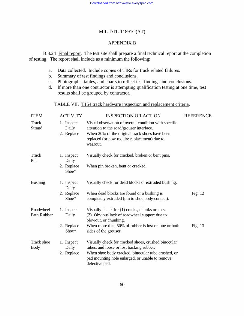
MIL-DTL-11891G(AT)
APPENDIX B
60
B.3.24 Final report. The test site shall prepare a final technical report at the completionof testing. The report shall include as a minimum the following:
a. Data collected. Include copies of TIRs for track related failures.b. Summary of test findings and conclusions.c. Photographs, tables, and charts to reflect test findings and conclusions.d. If more than one contractor is attempting qualification testing at one time, test
results shall be grouped by contractor.
TABLE VII. T154 track hardware inspection and replacement criteria.
ITEM ACTIVITY INSPECTION OR ACTION REFERENCE
TrackStrand
1. Inspect Daily
Visual observation of overall condition with specificattention to the road/grouser interface.
2. Replace When 20% of the original track shoes have beenreplaced (or now require replacement) due towearout.
TrackPin
1. Inspect Daily
Visually check for cracked, broken or bent pins.
2. Replace Shoe*
When pin broken, bent or cracked.
Bushing 1. Inspect Daily
Visually check for dead blocks or extruded bushing.
2. Replace Shoe*
When dead blocks are found or a bushing iscompletely extruded (pin to shoe body contact).
Fig. 12
RoadwheelPath Rubber
1. Inspect Daily
Visually check for (1) cracks, chunks or cuts. (2) Obvious lack of roadwheel support due toblowout, or chunking.
2. Replace Shoe*
When more than 50% of rubber is lost on one or bothsides of the grouser.
Fig. 13
Track shoeBody
1. Inspect Daily
Visually check for cracked shoes, crushed binoculartubes, and loose or lost backing rubber.
2. Replace When shoe body cracked, binocular tube crushed, orpad mounting hole enlarged, or unable to removedefective pad.
Downloaded from http://www.everyspec.com
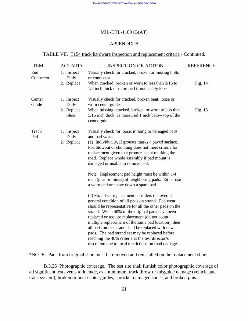
MIL-DTL-11891G(AT)
APPENDIX B
61
TABLE VII. T154 track hardware inspection and replacement criteria - Continued.
ITEM ACTIVITY INSPECTION OR ACTION REFERENCEEndConnector
1. Inspect Daily
Visually check for cracked, broken or missing boltsor connector.
2. Replace When cracked, broken or worn to less than 3/16 to1/8 inch thick or retorqued if noticeably loose.
Fig. 14
CenterGuide
1. Inspect Daily
Visually check for cracked, broken bent, loose orworn center guides.
2. Replace Shoe
When missing, cracked, broken, or worn to less than5/16 inch thick, as measured 1 inch below top of thecenter guide
Fig. 15
TrackPad
1. Inspect Daily
Visually check for loose, missing or damaged padsand pad wear.
2. Replace (1) Individually, if grouser marks a paved surface. Pad blowout or chunking does not meet criteria forreplacement given that grouser is not marking theroad. Replace whole assembly if pad mount isdamaged or unable to remove pad.
Note: Replacement pad height must be within 1/4inch (plus or minus) of neighboring pads. Either usea worn pad or shave down a spare pad.
(2) Strand set replacement considers the overallgeneral condition of all pads on strand. Pad wearshould be representative for all the other pads on thestrand. When 40% of the original pads have beenreplaced or require replacement (do not countmultiple replacement of the same pad location), thenall pads on the strand shall be replaced with newpads. The pad strand set may be replaced beforereaching the 40% criteria at the test director’sdiscretion due to local restrictions on road damage.
*NOTE: Pads from original shoe must be removed and reinstalled on the replacement shoe.
B.3.25 Photographic coverage. The test site shall furnish color photographic coverage ofall significant test events to include, as a minimum, track throw or misguide damage (vehicle andtrack system); broken or bent center guides; sprocket damaged shoes; and broken pins.
Downloaded from http://www.everyspec.com

MLL-DTL-1189lG(AT)
APPENDIX B
B.3.25. 1 A@icab]e information. Together with the photographic coverage, applicableinformation (manufacturer, serial number, test course, mileage sustained, etc.) shall be recorded
. and accompany the photographs. This data is to be included in the final report.
B.3.26 Distribution of rer)orts. The distribution of test incident reports and final reportsshall be as specified by the Preparing Activity.
T154 Track Shoe Assembly
P/N 12268550-1
fI @’
PLAIN NUTP/N 12268561
ENDP/N
CONNECTOR12268551
CAP SCREWP/N 12268563 /
/
LINK ASSEMBLYP/N 12268552
FIGURE 10. T 154 Track Hardware illustration.
62
Downloaded from http://www.everyspec.com

MIL-DTL-11891G(AT)
APPENDIX B
<
stamped alphanumeric identificationin area between track pins(inboard & outboard side of shoes)
FIGURE1l. Track~hoemarking.
63
Downloaded from http://www.everyspec.com

MIL-DTL-1 1891G(AT)
APPENDIX B
r DISTORTED SHOE
~NORML POSITION
PIN QND/~ SHOESEPARATED FROHB-H-(1NG (INSIDE)
FIGURE 12. “DeadTrackBlock’’bushn~c heck.
64
Downloaded from http://www.everyspec.com

MIL-DTL-1 189lG(AT)
APPENDIX B
h\(( 50?4Of VOlume
FIGURE 13. Roadwheel uath rubber inspection criteria.
FIGURE 14. End connector ins~ection criteria.
65
Downloaded from http://www.everyspec.com
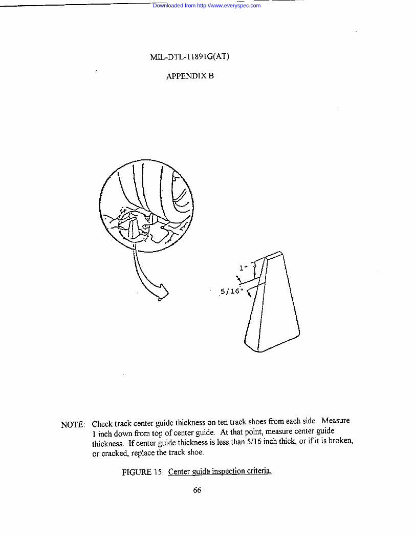
MIL-DTL-1 1891G(AT)
APPENDIX B
5/
NOTE: Check track center ~idettichess ontentrack shoes fiomeach side. Measure1 inch down from top of center guide. At that point, measure center guidethickness. If center guide thickness is less than 5/16 inch thick, or if it is broken,or cracked, replace the track shoe.
FIGURE 15. Center mide inspection criteria.
66
Downloaded from http://www.everyspec.com
MIL-DTL-11891G(AT)
APPENDIX C
67
T107 TRACK ON-VEHICLE TEST PLAN
C.1 SCOPE
C.1.1 Scope. This appendix defines a set of instructions and requirements to be used forconducting all integral pad track vehicle qualification tests. Although this appendix is specific innature, the Preparing Activity may amend this appendix with a more detailed set of instructions tomeet the needs of the particular test. The requirements of this appendix are not to be changedwithout prior permission from the Preparing Activity. This appendix is a mandatory part of thisspecification. The information contained herein is intended for compliance.
C.2 APPLICABLE DOCUMENTS
C.2.1 Drawings.
7069543 - Bolt.8382359 - Wedge.8382360 - Bolt.8705894 - Cap.8705897 - Guide.8705899 - Link Assembly.8705914 - T-107 Track.8705919 - Connector.
C.2.2 Standards.
MS51943 - Nut, Self-Locking, Hexagon-Prevailing Torque, For CriticalInstallations, 250°F, UNC-3B and UNF-3B.
C.3 REQUIREMENTS
C.3.1 Test program review. A start of test meeting will be held at the test site on a dateand time to be established by the Preparing Activity. Any additional review meetings shall bescheduled only if considered necessary by the Preparing Activity.
C.3.2 Test site access. Access to the test site will be required by Government personnelon a continuous basis to conduct their test responsibilities. Contractor personnel shall not beallowed test site access without specific approval from the Preparing Activity.
Downloaded from http://www.everyspec.com

MIL-DTL-11891G(AT)
APPENDIX C
68
C.3.3 Test program scope. This test will be accomplished by assembling themanufacturer's T107 track samples on an M88 series vehicle and operated to the requirements ofthis appendix.
C.3.4 T107 Track design characteristics. The T107 track is a double-pin track with anintegral pad. See figure 16 for a T107 track illustration with an associated parts listing.
C.3.5 Test course. The test course to be used for conducting all on-vehicle qualificationtests will be selected by the Preparing Activity. The preferred course is located at the U.S. ArmyProving Ground (YPG), Yuma, Arizona. Yuma has been traditionally selected for on-vehicletrack testing because of climate, course, and test result consistency. The following standard tracklaying vehicle (tank and other tracked vehicles) test courses at YPG are designated for testingtrack for this specification.
a. Paved course. The dynamometer course is a 2-mile, smooth, near-level(0.8 percent grade) 30-foot wide roadway with 500-foot radius turnarounds ateach end, surfaced with a high strength asphalt. The course is located at anelevation of approximately 470 feet above sea level and is staked at 0.1-mileintervals throughout its length with accurately surveyed distance markers.
b. Gravel course. The tank gravel course is a 3.6-mile compacted and graded gravelcourse and is for testing track laying vehicles under conditions simulating asecondary gravel road. The course consists of short straight sections and curves ofvarying radii with many moderate and sharp turns.
c. Hilly cross-country course. The tank hilly cross-country B course is 2.7 miles longand has short steep grades (35 percent) with a greater proportion of slopes lessthan 20 percent. This course has surfaces varying from sand and gravel to exposedbedrock. The loose gravel, sharp stones and rocks present a severe cutting andabrasion problem for tracks and roadwheels.
d. Level-cross country course. The tank level cross-country course traverses areas oflevel, sandy terrain with many bumps that provide a severe test of track layingvehicles. The dust conditions are typical of cross-country operation on dry soil. One lap is 6.7 miles.
Downloaded from http://www.everyspec.com

MIL-DTL-11891G(AT)
APPENDIX C
69
e. Hilly cross- country course (with a vehicle in tow). When towing a vehicle ofequal weight, the recommended course is the “Truck Hilly Course”. This course is2.2 miles long in one complete scenario. One mile of the course is in the form ofrolling hills with the second mile a number of steep but controllable hills. Thecourse consists of mostly gravel surfaces with the lower portion having sandy soil.
It is operated in both clockwise and counterclockwise directions. The turns allow for safeoperation when towing a vehicle of equal weight.
C.3.5.1 Operational mode summary. The vehicle shall perform to the requirements asspecified in table VIII. When towing, towed load shall be a vehicle of equal weight to the testvehicle.
Table VIII. Road test.
Course Mileage and speeds Vehicle loading
Hard/gravel 240 miles at varying Simulated combat payloadsurface speeds up to maximum. towed load for 30% of
specified test mileage.
Level cross- 480 miles at varying Simulated combat payloadcountry speeds up to maximum. towed load for 35% of
specified test mileage.
Hilly cross- 336 miles at varying Simulated combat payload.country speeds up to maximum.
Hilly cross- 144 miles at varying Simulated combat payloadcountry (with speeds up to maximum. and towed load.a vehicle intow)
C.3.5.2 Climatological conditions. In order to expose the track test samples to themaximum “hot” weather conditions, vehicle road testing shall be scheduled to start no earlier than1 March and no later than 1 September of the same calendar year.
Downloaded from http://www.everyspec.com

MIL-DTL-11891G(AT)
APPENDIX C
70
C.3.6 Track delivery and storage. Track shoe/pad samples are to be delivered to the testsite by a date specified by the Preparing Activity. Adequate time must be allowed for test sitepersonnel to inspect, mark, and install the hardware so as not to impact the projected test startdate. A secured area must be made available during and after the test for each of the trackshoe/pad samples. The samples received will be placed in a shaded area that prevents directsunlight from shining on the track pads during storage and assembly operations. The reduction ofvariables such as solar heating of the pads in a stack while other are shaded and, therefore, cooleris mandatory. Any condition that might influence the relative performance of the track shoes/padsare to be held as uniform as possible.
C.3.7 Contractor hardware requirements. For the qualification road test, the contractortest sample shall consist of 50 complete T107 track shoe assemblies (see C.3.10 for strandconfiguration). In addition, the following spare hardware shall be required: (a) 45 completeT107 assemblies, to include all connecting components. (b) The contractor shall ship 15 trackblocks for laboratory testing. Interested parties should contact the preparing activity for a specificaddress for shipment of the 15 track blocks.
C.3.8 Initial inspection/preparation for test. The test site shall perform a receivinginspection of the M88 series vehicle(s) to be used for the test. The basic test vehicle(s) will bevisually and functionally checked with specific attention given to suspension, electrical systems,hydraulic systems, and automotive controls and accessories. Any damage or improper operationwill be repaired/corrected to ensure the vehicle(s) will be capable of meeting the test requirementsdefined by this appendix.
C.3.8.1 Track qualification samples. Contractor supplied track qualification samples willbe inspected to ensure no physical damage has occurred in shipment, that the required number ofsamples and spares have been provided and that all components are properly identified.
C.3.9 Track identification. To aid in failure and part life tracking, all track shoes,including spares, shall be identified to a manufacturer by permanent sequential number/lettercodes applied to the metal portion of the shoe body. The test site shall apply the number/lettercodes to the test track shoes prior to vehicle installation.
C.3.9.1 Track assembly marking. All contractor supplied track assemblies shall bestamped with a lead designator alpha character only, prior to track break-in (see C.3.16).Following break-in, any failed shoes shall be removed and the remaining shoes shall besequentially numbered. The track shoes shall be marked on both the inboard and outboard faces,
Downloaded from http://www.everyspec.com

MIL-DTL-11891G(AT)
APPENDIX C
71
in the recessed area between the track pins as illustrated in figure 17. An example of the codingsystem to be used is as follows: X01, X02 .... X160 (X for Contractor ABC and 1,2,3 etc. fornumeric shoe designation). The test site shall contact the Preparing Activity to request a codeletter identification upon receipt of a contractors supplied hardware.
C.3.10 Track shoe installation pattern. Each vehicle will have the capacity to test threecontractors samples. Each strand will consist of 27 assemblies from each of three contractors andthree Government furnished T107 assemblies. The Government furnished assemblies will beremoved, as required, to maintain track tension. Two transition shoes (one of each of twodifferent contractors) at the connection points will not be considered in the qualification sample,making the qualification sample size 25 in each of two strands. The track shoe installation patternon the M88 series vehicle shall be provided to the test site by the Preparing Activity. Trackinstallation shall be accomplished in accordance with the appropriate technical manuals.
C.3.11 Load condition. For the test, the weight of the M88 vehicle shall be adjusted to112,000 pounds, plus or minus 400 pounds. The load shall be distributed approximately equal oneach track when on a level surface.
C.3.12 Pivoting of vehicles. Pivot steering of vehicles during break-in and qualificationtesting is to be-kept at a minimum. Sudden braking action shall also be avoided to the extentpossible.
C.3.13 Track tension adjustments. All tension adjustments shall be made prior to the startof the test as well as during test operations. As a minimum, track tension shall be checked on adaily basis. These adjustments shall be made after inspection faults have been corrected. Tracktension requirements can be found in the latest technical manuals for the M88 series vehicle.
NOTE: Low track tension will cause thrown tracks, broken or bent pins, and broken endconnectors and center guides. High track tension shall also be avoided. Track pins will break andtracks will be thrown, the track adjuster or grease gun shall be kept from contacting the trackshoe rubber parts. Any grease or oil accidentally contacting the shoe shall be immediately wipedoff.
C.3.14 Track component replacement. Track shoe assembly replacements are requiredbased on meeting the failure criteria for any number of component parts (bushing, roadwheel pathrubber, center guide, or shoe body damage). The component failure criteria is detailed in tableIX. The individual shoe replacements shall be made in the same strand location as the respectivefailed shoes.
Downloaded from http://www.everyspec.com

MIL-DTL-11891G(AT)
APPENDIX C
72
C.3.14.1 Hardware torque check. When track shoes, center guides, or end connectorsare replaced, the new hardware must be torqued checked after the first 50 miles of operation.
C.3.15 Torque values. All T107 track hardware shall be torqued to the following valuesand in accordance with proper maintenance procedures:
Connector wedge bolt 180 - 200 lb-ft.Center guide nuts 300 - 320 lb-ft.
C.3.l6 Break-in run. The purpose of the break-in run procedure is to simulate the naturalaging process afforded production/spare track during normal transit/storage periods before actualvehicle use. All test samples (to include spares) shall be broken in prior to the road test by havingthe vehicle on which they are installed, continuously operated for 45 miles on a paved road(concrete, asphalt, or macadam) as follows:
Division of Speed Distancebreak-in run m.p.h. (max) miles (min)
a 10 15b 15 15c 20 15
C.3.16.1 Vehicle operation. The vehicle shall be operated in both directions for one-halfof the total vehicle distance.
C.3.16.2 Track cooling. During the break-in run, the track shall be allowed to coolbetween each phase of testing. This cooling of the track can be verified through one of thefollowing two procedures.
C.3.16.2.1 Track roadwheel path surface. The track roadwheel path surface shall becooled to the point where the palm of the hand can be held to the surface in excess of 10 seconds.
C.3.16.2.2 Speed change cool down. Cool down between speed changes shall require theuse of a device used to measure the temperature of the rubber pads (see figure 7 for adiagrammed example of this type of device). Measurements should be taken from both theroadwheel side and the road side. A reading of 130 degrees or less should be recorded prior torestart of the break-in.
Downloaded from http://www.everyspec.com

MIL-DTL-11891G(AT)
APPENDIX C
73
C.3.16.3 Visual inspection. Between each division of the break-in run, a visual inspectionshall be made of the track and the component parts. The inspection shall be in accordance withthe inspection and replacement criteria found in the table IX. Hardware shall be re-torqued ifnoticeably loose. After break-in, all hardware shall be torqued 100% to values specified inC.3.15.
C.3.16.4 Track failures. Any track failures which occur during break-in do not counttowards the failure criteria. Further, any failures during break-in do not reduce the originalsample sizes. Track shoes failed during break-in shall be replaced with spares and noted on a TestIncident Report (TIR). The track shoes comprising a strand after break-in (including the recordedspares inserted for any failures during break-in) shall be denoted as the original strand sample atthe start of test. Break-in mileage shall be counted toward the qualification mileage requirement.
C.3.16.5 Spare track. All spare track shall be installed on a vehicle and broken in beforetest start up. The break-in shall be performed in accordance with C.3.16. After completion of thebreak-in run, the track shall be removed from the vehicle and stored for future use during thequalification test.
C.3.17 Test procedure. After completion of the break-in run, the vehicle shall run to theoperational mode summary found in C.3.5.1 until the track being tested for qualification has metthe failure criteria (see C.3.19) or the 1200 mile requirement is exceeded. Testing may be stoppedat any time at the discretion of the test director.
C.3.17.1 Mission scenarios. During the test, operators are to run mission scenarios asspecified by the Preparing Activity.
C.3.17.2 Track switching. Upon completion of the first 500-mile mission scenario, thetrack strands shall be removed from the vehicle, inspected for overall condition, and switched tothe opposite side. At 1000 miles, the track strands shall be removed from the vehicle, inspectedfor overall condition, and switched to the opposite side. Repeat this switching procedure forevery 500 miles of testing.
C.3.18 Inspection and replacement criteria. Inspection and replacement criteria duringthe on-vehicle test shall be in accordance with the table IX.
C.3.19 Failure criteria. Failure of a contractor's track will be established when 20% of itstotal shoe samples have reached wearout and/or need replacement (see table IX).
Downloaded from http://www.everyspec.com
MIL-DTL-11891G(AT)
APPENDIX C
74
C.3.19.1 Track failure (break-in). Any track failures which occur during break-in or aredamaged as a result of the following incidents will not be counted against qualificationrequirements:
a. Mechanical failure of non track parts resulting in track damage.b. Sprocket damaged shoes.
C.3.20 Disposition of track test hardware. All track test hardware shall be retained at thetest site pending disposal instructions, including failed track components. Track that is defectiveor has completed testing may be stored outdoors while waiting for disposition instructions. It isessential that each manufacturer’s track samples are not commingled with samples from anothermanufacturer.
C.3.20.1 Failed track components. All failed track components shall be tagged andmarked so as to identify accumulated test miles and cross reference to daily logs or test reports, asappropriate to provide for traceable component failure history.
C.3.20.2 Hardware (failure analysis). Hardware required for failure analysis shall beprovided to the Preparing Activity upon request.
C.3.21 Vehicle disposition. Upon completion of the test and inspections, the vehicle shallbe returned to the original pretest condition. Vehicle disposition instructions will be issued by thePreparing Activity.
C.3.22 Documentation/test reporting/photographic coverage. Any test incidents relatedto track, suspension and /or drive train components shall be documented on AMC Form 2134,Test Incident Report (TIR) or comparable test reporting document. The test site shall providethese reports to the Preparing Activity as they are generated. Each TIR or other test reportingdocument shall include as a minimum the following:
a. Description of failed component/part (noun).b. Mileage track has endured.c. Code/Serial number identification of failed component and code/serial number of
replacement component.d. Vehicle registration number.e. Date of incident.f. Description of incident. Description shall be detailed and include cause, if evident.g. Test course where incident occurred, if known.h. Estimated speed of vehicle when incident occurred.
Downloaded from http://www.everyspec.com
MIL-DTL-11891G(AT)
APPENDIX C
75
i. Test environment at time of incident.j. Disposition of failed part. Hold and tag failed part.k. Test report number (beginning with number 1, continuing in chronological order).
Supplements to a specific number shall be identified with a letter (i.e., T0001A).l. Authorized signature.
C.3.22.1 Track incidents. All track incidents determined to be major (that is, trackthrows, misguides, etc.) shall be immediately reported to the Preparing Activity.
C.3.23 Final report. The test site shall prepare a final technical report at the completionof testing. The report shall include as a minimum the following:
a. Data collected. Include copies of TIRs for track related failures.b. Summary of test findings and conclusions.c. Photographs, tables, and charts to reflect test findings and conclusions.d. If more than one contractor is attempting qualification testing at one time, test
results shall be grouped by contractor.
C.3.24 Photographic coverage. The test site shall furnish color photographic coverage ofall significant test events to include, as a minimum, track throw or misguide damage (vehicle andtrack system), broken or bent center guides, sprocket damaged shoes, and broken pins.
C.3.24.1 Applicable information. Together with the photographic coverage, applicableinformation (manufacturer, serial number, test course, mileage sustained, etc.) shall be recordedand accompany the photographs. This data is to be included in the final report.
C.3.25 Distribution of reports. The distribution of test incident reports and final reportsshall be as specified by the Preparing Activity.
Downloaded from http://www.everyspec.com

MIL-DTL-11891G(AT)
APPENDIX C
76
TABLE IX. T107 track hardware inspection and replacement criteria.
ITEM ACTIVITY INSPECTION OR ACTION REFERENCE
TrackStrand
1. Inspect Daily
Visual observation of overallcondition with specific attention to theroad/grouser interface.
2. Replace When 20% of the original track shoeshave been replaced (or now requirereplacement) due to wearout.
Fig. 20
Track Pin 1. Inspect Daily
Visually check for cracked, broken orbent pins.
2. 500 miles Hammer-Ring check at site discretion. Fig. 183. Replace Shoe
When pin broken, bent or cracked.
Bushing 1. Inspect Daily
Visually check for dead blocks orextruded bushing.
2. Replace Shoe
When dead blocks are found or abushing is completely extruded (pin toshoe body contact).
Fig. 19
RoadwheelPath Rubber
1. Inspect Daily
Visually check for (1) cracks, chunksor cuts. (2) Obvious lack ofroadwheel support due to blowout, orchunking.
2. Replace Shoe
When more than 50% of rubber islost.
Fig. 20
Track ShoeBody
1. Inspect Daily
Visually check for cracked shoes. Daily crushed binocular tubes, andloose or lost backing rubber.
2. Replace When shoe body cracked, binoculartube crushed.
Downloaded from http://www.everyspec.com

MIL-DTL-11891G(AT)
APPENDIX C
77
TABLE IX. T107 track hardware inspection and replacement criteria - Continued.
ITEM ACTIVITY INSPECTION OR ACTION REFERENCE
EndConnector
1. Inspect Daily
Visually check for cracked, broken ormissing bolts or connector.
2. Replace When checked, broken or worn. toless than 1/8 inch thick.
Fig. 21
CenterGuide
1. Inspect Daily
Visually check for cracked, broken,bent loose or worn center guides.
Fig. 22
2. Replace Shoe
When missing, cracked, broken, orworn to less than 1/2 inch thick asmeasured 1 inch below top to thecenter guide.
RoadsideRubber
1. Inspect Daily
Visually check for rubber wear orloss of rubber.
2. Replace Shoe
Chevron is less than 1/2 inch*or the metal is exposed.
Figs. 20 and 23
*NOTE: At the test site discretion, chevron wear can be measured by a “Go/No/-Go” devicehaving one leg sitting on top of one end plate of a block and a second leg sitting on top of theother end plate, the legs joined with a straight strip running parallel to the rubber surface of theground side of the shoe. If both legs of the measuring device touch, at the same time, the twohigh points of the end plates, the wear on the ground side will be considered worn out.
Downloaded from http://www.everyspec.com

.
MIL-DTL-11891G(AT)
APPENDIX C
P/ii 8705914
SELF-LOCKING NUT
P/N HS51943-18 __----&Ii
II
GUIDEP/N 8705897
$
. .
LINK ASSEMBLY
I
Ic~~ 1p/N 87058siI
1
*BOLTP/N 7069543
‘i!
8705899
! ~ BOLTP/N 8382360
i
69
CONNECTORP/N 8705919
WEDGEp/N 838235s
FIGURE 16. T107track hardware illustration.
78
Downloaded from http://www.everyspec.com
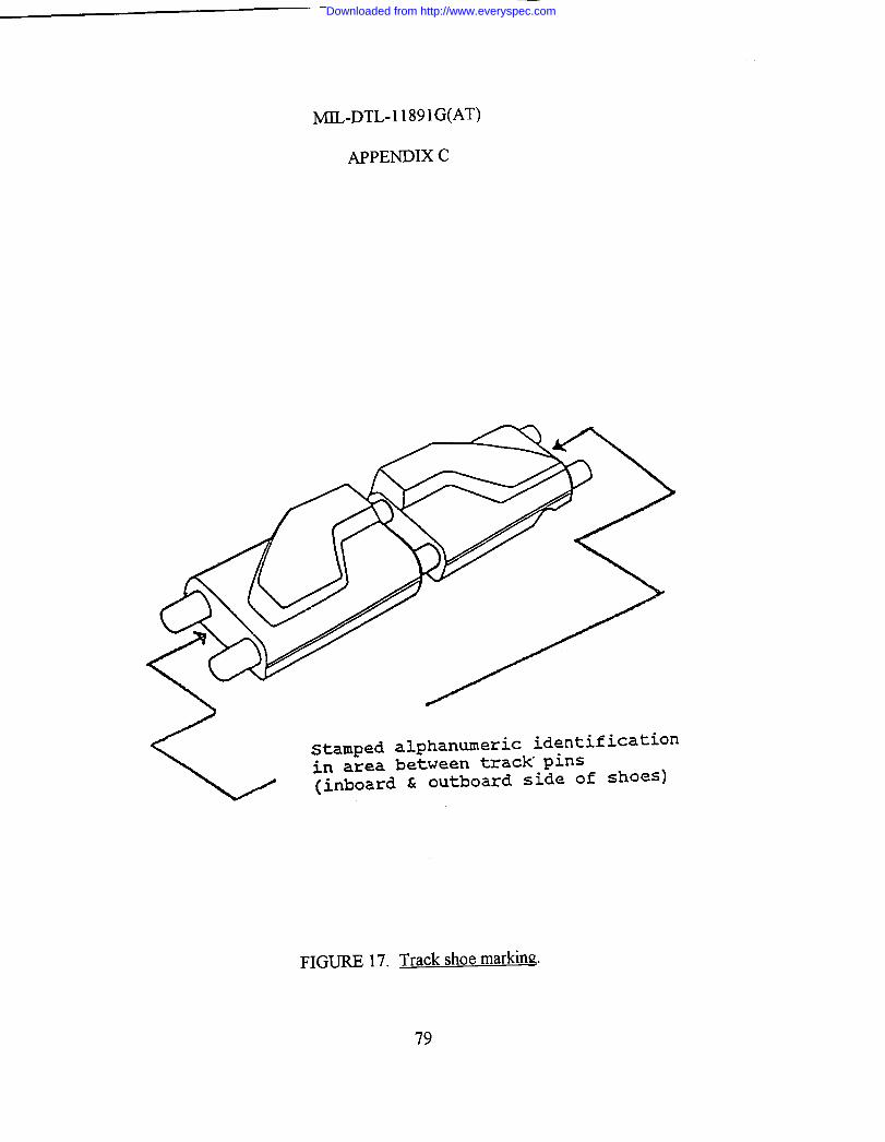
MIL-DTL-l 1891G(AT)
APPENDIX C
<
Stamped alphanweric identificationi.n area between track p~ns(inboard & outboard side of shoes)
FIGURE 17. Trackshoemarklng.
79
Downloaded from http://www.everyspec.com
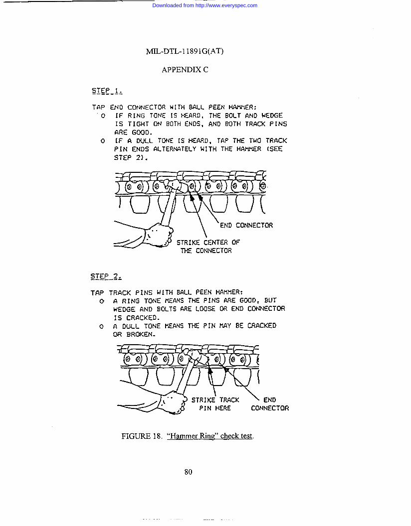
MIL-DTL-1 189lG(AT)
APPENDIX C
STEP 1----- -s
TAP ENO CONNECTOR HI TH MU PEEN I-WUIER:
o IF RING TONE [S HEARD, THE BOLT AND WEDGE
IS TIGHT ON BOTH ENDS, AND BOTH TRACK PINSARE GOOD.
o IF A DULL TONE [S HEARD, TAP THE TWO TRACKPIN ENDS ALTERNATELY WITH THE HAMER (SEESTEP 2).
STEP 2------:
TAP TRACK PINS WITH BALL PEEN NAMER:C) A RING TONE KEAN-S THE PINS ME GOOD, SLIT
wEDGE AND BOLTS ARE LOOSE OR END CON?+ECTOR
IS CRACKED.
O G DULL TONE MEANS THE PIN HAY 8E CRACKEDOR BROKEN.
ENDNNECTOF(
FIGURE 18. “HarnrnerRin~’’checktest.
80
Downloaded from http://www.everyspec.com

~-DTL-l 1891G(AT)
APPENDIX C
r DIsTORTED SW
/ NORHAL POSITION
)
/
~ PIN ~)4D/OR SHOE
SEPARATED F~
BUSHING (INSIDEI
FIGURE 19. “DeadTrackBlock’’buskngc heck.
81
Downloaded from http://www.everyspec.com
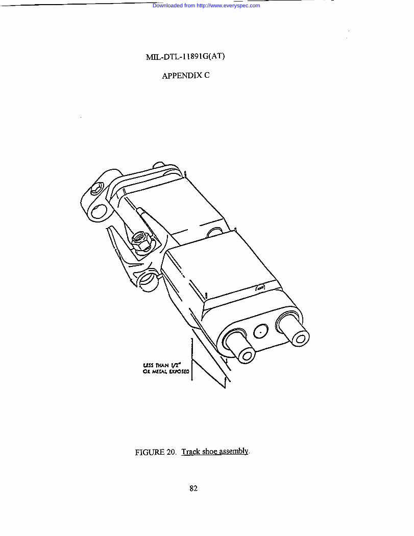
MIL-DTL-11891G(AT)
APPENDIX C
FIGURE 20. Track shoe assembly.
82
Downloaded from http://www.everyspec.com
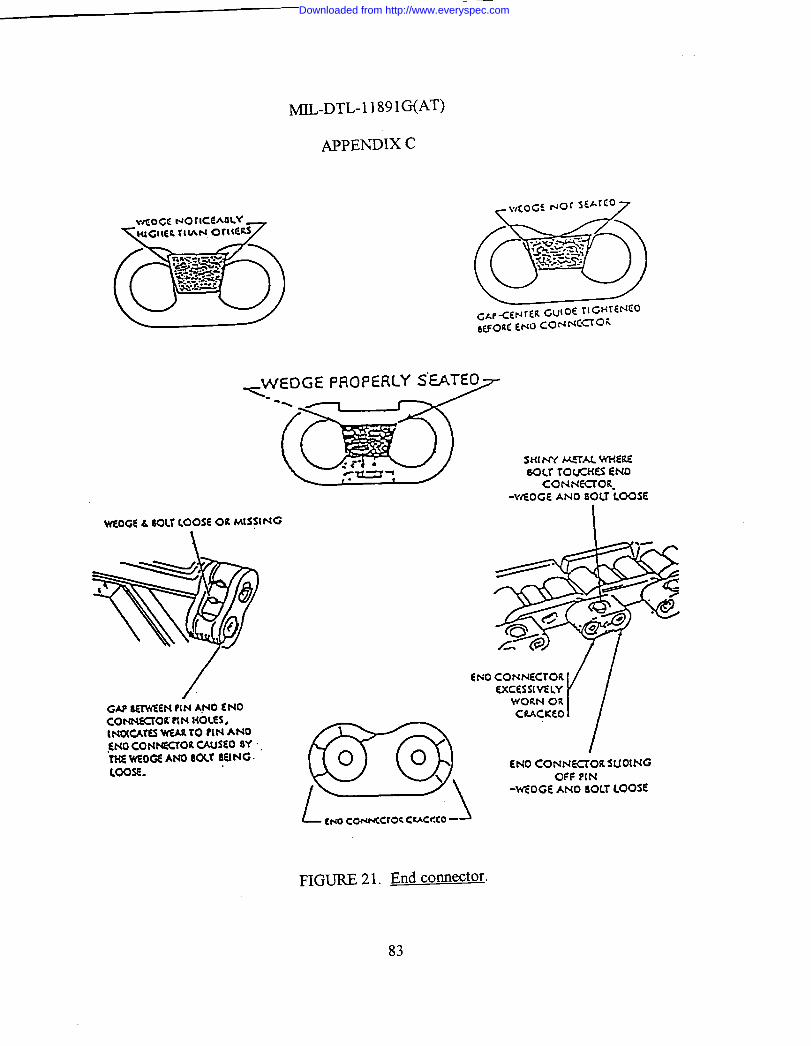
MIL-DTL-11891G(AT)
APPENDIX C
+IWEDGE PROPERLY SEATEO- .%
S14 NY MTAL W-ME6ocr rouct(EsWO
CO NN=OR.-WEOGE ANO 80LT LOOSE
WEOGE & 60Lr LOOSE OR MS:(NG
cm
GAP 8~EN ?(N Wo ~NOCONN~OK RN HOW.lNOV=r~ WAR TO PIN ANO.0+0 CON-OR ws~o SYT=WOG ANO 80U 6EING.
cm
00I.00SE.
040 CONNECTOR SUOING
\
1
OFF P(N
L-wEOGE ANO 80LTLOOSE
cf.iocorwcroc cuccco -
FIGURE 21. End connector,
83
Downloaded from http://www.everyspec.com

MIL-DTL-11891G(AT)
APPENDIX C
/
CENTERGUIDE MISSING
BENT, CRACKED, BROKEN
BOLT AND NUTMISSING ORNOTICEABLYFEWER THREADSSHOWING
FIGURE 22. Center Wide.
84
Downloaded from http://www.everyspec.com
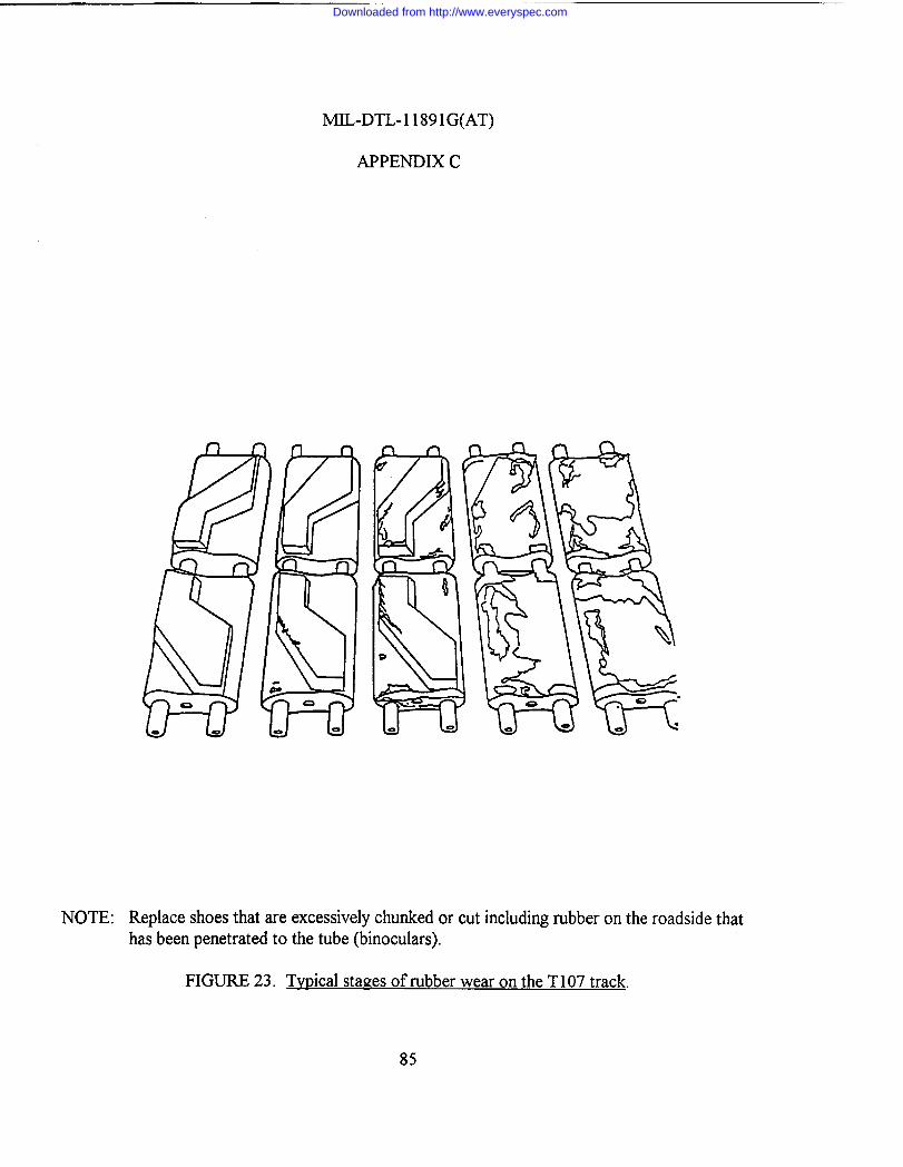
MIL-DTL-1 1891G(AT)
APPENDIX C
NOTE: Replace shoes that are excessively chunked or cut including rubber on the roadside thathas been penetrated to the tube (binoculars).
FIGURE 23. Typical stages of rubber wear on the T107 track.
85
Downloaded from http://www.everyspec.com

MIL-DTL-11891G(AT)
APPENDIX D
86
T157I PAD ON-VEHICLE TEST PLAN
D.1 SCOPE
D.1.1 Scope. This appendix defines a set of instructions and requirements used forconducting the T157I pad vehicle qualification test. Although this appendix is specific in nature,the Preparing Activity may amend this appendix with a more detailed set of instructions to meetthe needs of the particular test. This appendix will not be changed without prior permission fromthe Preparing Activity. This appendix is a mandatory part of this specification. The informationcontained herein is intended for compliance.
D.2 APPLICABLE DOCUMENTS
D.2.1 Drawings.
12359469 - Pad, Track Shoe.12359510 - Parts Kit, Pad, Aluminum Backing Plate.12466485 - Parts Kit, Pad, Steel Backing Plate.
D.2.2 Standards.
MS51943 - Nut, Self-Locking, Hexagon-Prevailing Torque, For CriticalInstallations, 250°F, UNC-3B and UNF-3B.
D.3 REQUIREMENTS
D.3.1 Test program review. A start of test meeting will be held at the test site on a dateand time to be established by the Preparing Activity. Any additional review meetings shall bescheduled only if considered necessary by the Preparing Activity.
D.3.2 Test site access. Access to the test site will be required by Government personnelon a continuous basis to conduct their test responsibilities. Contractor personnel shall not beallowed test site access without specific approval from the Preparing Activity.
D.3.3 Test program scope. This test will be accomplished by assembling themanufacturer’s T157I track pad samples on a Bradley Fighting Vehicle and operated to therequirements of this appendix.
Downloaded from http://www.everyspec.com
MIL-DTL-11891G(AT)
APPENDIX D
87
D.3.4 T157I design characteristics. The T157I pad is part of a single pin track. Seefigure 24 for a T157I track illustration.
D.3.5 Test course. The Preparing Activity will select the test course for conducting allon-vehicle qualification tests. The preferred course is located at the U.S. Army Yuma ProvingGround (YPG), Yuma, Arizona. Yuma has been traditionally selected for on-vehicle track testingbecause of climate, course, and test result consistency. The following standard track layingvehicle (tank and other tracked vehicles) test courses at YPG are designated for testing track forthis specification.
a. Paved course. The dynamometer course is a 2 mile, smooth, near level(0.8 percent grade), 30 foot wide roadway with 500 foot radius turnarounds ateach end, surfaced with a high strength asphalt. The course is located at anelevation of approximately 470 feet above sea level and is staked at 0.1 mileintervals throughout its length with accurately surveyed distance markers.
b. Gravel course. The tank gravel course is a 3.6 mile compacted and graded gravelcourse and is for testing track laying vehicles under conditions simulating asecondary gravel road. The course consists of short straight sections and curves ofvarying radii with many moderate and sharp turns.
c. Hilly cross-country course. The tank hilly cross-country B course is 2.7 miles longand has short steep grades (35 percent) with a greater proportion of slopes lessthan 20 percent. This course has surfaces varying from sand and gravel to exposedbedrock. The loose gravel, sharp stones, and rocks present a severe cutting andabrasion problem for tracks and roadwheels.
d. Level cross-country course. The tank level cross-country course traverses areas oflevel, sandy terrain with many bumps that provide a severe test of track layingvehicles. The dust conditions are typical of cross-country operation on dry soil. One lap is 6.7 miles.
D.3.6 Operational mode summary. The operational mode summary for the test shallconsist of 21% paved (concrete, asphalt, or macadam), 45% on gravel composed mostly of smallstones, and 34% on cross-country (equal amount of hilly and level). During the test, the vehicleshall not traverse more than 50 continuous miles over any type of terrain. Vehicle directionaround the test courses shall be changed periodically to assure approximately equal clockwise andcounterclockwise test operation.
Downloaded from http://www.everyspec.com

MIL-DTL-11891G(AT)
APPENDIX D
.
FIGURE 24. T 1571track hardware illustration
88
Downloaded from http://www.everyspec.com
MIL-DTL-11891G(AT)
APPENDIX D
89
D.3.6.1 Fifty mile scenario. During the test, operators are to run one 50 mile scenario ata time in accordance with the mission profile requirements stated below. A mission profilerequirement will consist of the following:
Secondary road………………..22.5 milesPaved road…………………….10.5 milesCombined X Country………….17 miles
D.3.7 Climatological conditions. In order to expose the track test samples to themaximum “hot” weather conditions, vehicle road testing shall be selected to start no earlier than1 March and no later than 1 September of the same calendar year.
D.3.8 Pad delivery and storage. Pad samples shall be delivered to the test site by a dateas specified by the Preparing Activity. Adequate time must be allowed for test site personnel toinspect, mark, and install the hardware so as not to impact the projected test start date. A securedarea must be made available during and after the test for each of the track pad samples. Thesamples received will be placed in a shaded area that prevents direct sunlight from shining on thetrack pads during storage and assembly operations. The reduction of variables such as solarheating of the pads in a stack while others are shaded and, therefore, cooler is mandatory. Anycondition that might influence the relative performance of the track pads shall be held as uniformas possible.
D.3.9 Contractor hardware requirements. For the qualification road test, the contractortest samples shall consist of 164 complete pad assemblies (to include self-locking nut,P/N MS51943). In addition, 136 spare pads (with self-locking nut, P/N MS51943) shall berequired.
D.3.10 Initial inspection/preparation for test. The test site shall perform a receivinginspection of the Bradley series vehicle to be used for the test. The basic test vehicle will bevisually and functionally checked with specific attention given to suspension, electrical systems,hydraulic systems, and automotive controls and accessories. Any damage or improper operationwill be repaired/corrected to ensure the vehicle will be capable of meeting the test requirementsdefined by this appendix.
D.3.10.1 Qualification sample inspection. Contractor supplied track pad qualificationsamples will be inspected to ensure no physical damage has occurred in shipment, that therequired number of samples and spares have been provided, and that all components are properlyidentified.
Downloaded from http://www.everyspec.com

MIL-DTL-11891G(AT)
APPENDIX D
90
D.3.11 Serial marking. Serial marking of pads may be required as specified by thePreparing Activity.
D.3.12 Pad installation (qualification). Pads supplied for pad qualification only will beinstalled on Government furnished T157I track assemblies.
D.3.13 Load condition of the vehicle. For the test, the weight of the Bradley vehicle shallbe adjusted to 64 375 pounds, plus or minus 500 pounds. The load shall be distributedapproximately equal on each track when on a level surface.
D.3.14 Pivoting of vehicle. Pivot steering of the vehicle during break-in and qualificationtesting is to be kept at a minimum. Sudden braking action shall also be avoided to the extentpossible.
D.3.15 Track tension adjustments. All tension adjustments shall be made prior to thestart of the test as well as during test operations. As a minimum, track tension shall be checkedon a daily basis. These adjustments shall be made after inspection faults have been corrected. Track tension requirements can be found in the latest technical manuals for the Bradley vehicle. NOTE: Low track tension will cause thrown tracks, broken or bent pins, and broken endconnectors and center guides. High track tension shall also be avoided. Track pins will breakand tracks will be thrown. The track adjuster or grease gun shall be kept from contacting thetrack rubber parts. Any grease or oil accidentally contacting the shoes shall be immediately wipedoff.
D.3.16 Track component replacement. Track shoe assembly replacements are requiredbased on meeting the failure criteria for any number of component parts (bushing, roadwheel pathrubber, center guide, or shoe body damage). The individual shoe replacements shall be made inthe same strand location as the respective failed shoes. In addition, if the pads meet theacceptance criteria, the pads from the original track shoe shall be reinstalled on the replacementshoe.
D.3.17 New hardware. When track shoes and pads are replaced, the new hardware mustbe torque checked after the first 50 miles of operation.
Downloaded from http://www.everyspec.com

MIL-DTL-11891G(AT)
APPENDIX D
91
D.3.17.1 Torque values. All T157I track hardware shall be torqued to the followingvalues and in accordance with proper maintenance procedures:
Pad nut - MS51943 135-155 lb-ftNut, self-locking - P/N 12308644-1 299-325 lb-ft(used on track shoe rod, see figure 24)
D.3.18 Break-in run. The purpose of the break-in run procedure is to simulate the naturalaging process afforded production/spare pads during normal transit/storage periods before actualvehicle use. All test samples (to include spares and all pads provided for qualification) shall bebroken in prior to the road test by having the vehicle on which they are installed, continuouslyoperated for 45 miles on a paved road (concrete, asphalt, or macadam) as follows:
Division Speed Distancebreak-in run m.p.h. (max) miles (min)
a 10 15b 15 15c 20 15
D.3.18.1 Vehicle operation. The vehicle shall be operated in both directions for one-halfof the total vehicle distance.
D.3.18.2 Track cooling (break-in). During the break-in run, the track shall be allowed tocool between each phase of testing. The cooling of the track can be verified through one of thefollowing two procedures.
D.3.18.2.1 Track roadwheel cooling. The track roadwheel path surface shall be cooled tothe point where the palm of the hand can be held to the surface backing in excess of 10 seconds.
D.3.18.2.2 Cool down between speed changes. Cool down between speed changes shallrequire the use of a device used to measure the temperature of the rubber pads (see figure 7 for adiagrammed example of this type of device). Measurements should be taken from both theroadwheel side and the roadside. A reading of 130 degrees or less should be recorded prior torestart of the break-in.
Downloaded from http://www.everyspec.com

MIL-DTL-11891G(AT)
APPENDIX D
92
D.3.18.3 Visual inspection (break-in). Between each division of the break-in run, a visualinspection shall be made of the track and the components parts. The inspection shall be inaccordance with the inspection and replacement criteria found in the table X. Hardware shall bere-torqued if noticeably loose. After break-in, all hardware shall be torqued 100% to values asspecified in D.3.17.1.
D.3.18.4 Track pad failure (break-in). Any track pad failures which occur during break-in do not count towards the failure criteria. Further, any failures during break-in do not reducethe original sample size. Pads failed during break-in shall be replaced with spares and noted on aTest Incident Report (TIR) or similar document. The pad assemblies comprising a strand afterbreak-in shall be denoted as the original strand sample at the start of test. Break-in mileage shallbe counted toward the qualification mileage requirement.
D.3.18.5 Spare pads. All spare pads shall be installed on a vehicle and broken in beforetest start up. The break-in shall be performed in accordance with D.3.17. After completion of thebreak-in run, the pads shall be removed from the vehicle and stored for future use during thequalification test.
D.3.19 Test procedure. After completion of the break-in run, the vehicle shall be run tothe operational mode summary found in D.3.6 until the pads being tested for qualification havemet the failure criteria (see D.3.20) or have exceeded the qualification requirement of 800 milespad life.
D.3.19.1 Track switching. Upon completion of the first 500 mile mission scenario, thetrack strands shall be removed from the vehicle, inspected for overall condition, and switched tothe opposite side. Unless otherwise specified by the Preparing Activity (see 6.2), the track padsshall be removed from the vehicle at 800 miles.
D.3.20 Failure criteria. Failure of a contractor’s pads will be established when 40% of theoriginal pad samples have reached wear-out and/or need replacement. For scoring purposes, thetest site shall not count multiple replacement of the same pad location.
D.3.20.1 Pad failure (break-in). Any pad failures which occur during break-in or startdamaged as a result of the following incidents will not be counted against qualificationrequirements:
a. Mechanical failure of non-track parts resulting in track pad damage.b. Sprocket damaged shoes.
Downloaded from http://www.everyspec.com

MIL-DTL-11891G(AT)
APPENDIX D
93
TABLE X. T157I track hardware inspection and replacement criteria.
ITEM ACTIVITY INSPECTION OR ACTIONTrack strand 1. Inspect daily.
2. Replace.
Visual observation of overall condition withspecific attention to the road/grouser interface.When 20% of the original track shoes havebeen replaced (or now require replacement dueto wearout).
Track pin 1. Inspect daily.
2. Replace shoe*.
Visually check for cracked, broken or bentpins.When pin broken, bent or cracked.
Bushing 1. Inspect daily.
2. Replace shoe*.
Visually check for dead blocks or extrudedbushing.When dead blocks are found or a bushing iscompletely extruded (pin to shoe bodycontact).
Roadwheelpath rubber
1. Inspect daily.
2. Replace shoe*.
Visually check for (1) cracks, chunks, or cuts. (2) Obvious lack of roadwheel support due toblowout or chunking.When more than 50% of rubber is lost.
Track shoebody
1. Inspect daily.
2. Replace.
Visually check for cracked shoes, crushedbinocular tubes, and loose or lost backingrubber.When shoe body cracked, binocular tubecrushed, or pad mounting hole enlarged, orunable to remove defective pad.
Center guide 1. Inspect daily.
2. Replace shoe*.
Visually check for cracked, broken, bent, looseor worn center guides.When missing, cracked, broken or worn to lessthan 3/8 inch thick as measured 1 inch belowtop to the center guide.
Track pad See D.3.20 and D.3.21.
*NOTE: Pads from original shoe must be removed and reinstalled on the replacement shoe.
Downloaded from http://www.everyspec.com

MIL-DTL-11891G(AT)
APPENDIX D
94
D.3.21 Inspection and replacement criteria. The track pad shall be replaced if the grousermarks a paved surface. Pad blowout or chunking does not meet criteria for replacement giventhat the grouser is not marking the road. The whole assembly shall be replaced if the pad mountis damaged or unable to remove pad. Replacement pad height must be within 1/4 inch (plus orminus) of neighboring pads. The test site shall use either a worn pad or shave down a spare pad.
D.3.21.1 Pad inspection. As a minimum, test site personnel shall inspect the pads on adaily basis or after approximately every 50 miles, whichever occurs first. During break-in, a visualinspection shall be made between each division of the break-in run.
D.3.22 Disposition of pad test hardware. All pad test hardware shall be retained at thetest site pending disposal instructions, including failed track pad components. Pads that aredefective or have completed testing may be stored outdoors while waiting for dispositioninstructions. It is essential that each manufacturer’s pad samples are not commingled withsamples from another manufacturer or other compound sample.
D.3.22.1 Failed track pad marking. All failed track pads shall be tagged and marked so asto identify accumulated test miles and cross reference to daily logs or reports, as appropriate toprovide for traceable component failure history.
D.3.22.2 Hardware (failure analysis). Hardware required for failure analysis shall beprovided to the Preparing Activity upon request.
D.3.23 Vehicle disposition. Upon completion of the test and inspections, the vehicle shallbe returned to the original pretest condition. Vehicle disposition instructions will be issued by thePreparing Activity.
D.3.24 Documentation/test reporting/photographic coverage. Any test incidents relatedto track, suspension, and/or drive train components shall be documented on AMC Form 2134,Test Incident Report (TIR) or comparable test reporting document. The test site shall providethese reports to the Preparing Activity as they are generated. Each TIR or other test reportingdocument shall include as a minimum the following:
a. Description of failed component/part (noun).b. Mileage pads have endured.c. Date of incident.d. Description of incident. Description shall be detailed and shall include cause, if
evident.e. Test course where incident occurred (if known).f. Estimated vehicle speed when incident occurred.
Downloaded from http://www.everyspec.com

MIL-DTL-11891G(AT)
APPENDIX D
95
g. Test environment at time of incident.h. Disposition of failed part. Hold and tag failed part.i. Test report number.j. Vehicle registration number.k. `Code/serial number identification of failed component and code/serial number of
replacement component.l. Authorized signature.
D.3.24.1 Major track incidents. All track incidents determined to be major, that is, trackthrows, misguides, etc., shall be immediately reported to AMSTA-TR-E/BFV.
D.3.25 Final report. The test site shall prepare a final technical report at the completionof testing. The report shall include as a minimum the following:
a. Data collected. Include copies of TIRs for track related failures.b. Summary of test findings.c. Photographs, tables, and charts to reflect test findings.d. If more than one contractor is attempting qualification testing at one time, test
results shall be grouped by contractor.
D.3.26 Photographic coverage. The test site shall furnish color photographic coverage ofall significant test events to include, as a minimum, track throw or misguide damage (vehicle andtrack system), broken or bent center guides, sprocket damaged shoes, and broken pins,representative sampling of pad failures, and a representative sampling of pads which have not metthe failure criteria.
D.3.26.1 Applicable information. Together with the photographic coverage, applicableinformation (manufacturer, serial number, test course, mileage sustained, etc.) shall be recordedand accompany the photographs. This data is to be included in the final report.
D.3.27 Distribution of reports. The distribution of test incident reports and final reportsshall be as specified by the Preparing Activity (see 6.2).
Custodian: Preparing Activity:Army - AT Army - AT
(Project 2530-0402)
Downloaded from http://www.everyspec.com

STANDARDIZATION DOCUMENT IMPROVEMENT PROPOSAL
1. The preparing activity must complete blocks 1, 2, 3, and 8. In block 1, both the document number and revisionletter should be given.
2. The submitter of this form must complete blocks 4, 5, and 7.3. The preparing activity must provide a reply within 30 days from receipt of the form.NOTE: This form may not be used to request copies of documents, nor to request waivers, or clarification of requirements on current contracts. Comments submitted on this form do not constitute or imply authorization towaive any portion of the referenced document(s) or to amend contractual requirements.
INSTRUCTIONS
I RECOMMEND A CHANGE:1. DOCUMENT NUMBER 2. DOCUMENT DATE (YYMMDD)
3. DOCUMENT TITLE
4. NATURE OF CHANGE (Identify paragraph number and include proposed rewrite, if possible. Attach extra sheets as needed.)
5. REASON FOR RECOMMENDATION
6. SUBMITTER
a. NAME (Last, First, Middle Initial) b. ORGANIZATION
c. ADDRESS (Include Zip Code) d. TELEPHONE (Include Area Code)(1) Commercial(2) AUTOVON
(If applicable)
7. DATE SUBMITTED (YYMMDD)
8. PREPARING ACTIVITYa. NAME b. TELEPHONE (Include Area Code)
(1) Commercial (2) AUTOVON(810) 574-8745 786-8745
c. ADDRESS (Include Zip Code)CommanderU.S. Army Tank-automotive and Armaments CommandATTN: AMSTA-TR-E/BLUEWarren, MI 48397-5000
IF YOU DO NOT RECEIVE A REPLY WITHIN 45 DAYS, CONTACT:Defense Quality and Standardization Office5203 Leesburg Pike, Suite 1403Falls Church, VA 22041-3466Telephone (703) 756-2340 AUTOVON 289-2340
DD Form 1426, OCT 89 Previous editions are obsolete. 198/290
MIL-DTL-11891G(AT) 980225
TRACK SHOE SETS, TRACK SHOE ASSEMBLIES, TRACK SHOE PADS AND TRACK SHOE BUSHINGS, VEHICULAR:
Downloaded from http://www.everyspec.com