installation and collectors maintenance instructions - buderus · pdf filesome parts may cause...
TRANSCRIPT
Installation and maintenance instructions
Vacuum tube collectors
For contractors
Read carefully
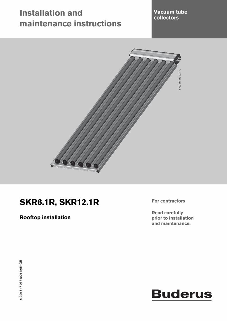
SKR6.1R, SKR12.1R
6 72
0 64
7 04
2-00
.1IT
L
prior to installation and maintenance.
Rooftop installation
6 72
0 64
7 05
7(2
011/
05)G
B

Table of contents
Table of contents
1 Key to symbols and safety instructions . . . . . 31.1 Explanation of symbols . . . . . . . . . . . . . . . . . 31.2 General safety information . . . . . . . . . . . . . . 3
2 Product information . . . . . . . . . . . . . . . . . . . . . . 42.1 Components and instructions . . . . . . . . . . . 42.2 Correct usage . . . . . . . . . . . . . . . . . . . . . . . . 52.3 EU Declaration of Conformity . . . . . . . . . . . 52.4 Standard delivery . . . . . . . . . . . . . . . . . . . . . 62.4.1 Mounting bracket . . . . . . . . . . . . . . . . . . . . . 62.4.2 Installation set . . . . . . . . . . . . . . . . . . . . . . . . 62.4.3 Connection sets (hydraulic connection) . . . 72.4.4 Collector . . . . . . . . . . . . . . . . . . . . . . . . . . . . 72.5 Data plate . . . . . . . . . . . . . . . . . . . . . . . . . . . 72.6 Specification . . . . . . . . . . . . . . . . . . . . . . . . . 8
3 Regulations . . . . . . . . . . . . . . . . . . . . . . . . . . . . . 8
4 Before installation . . . . . . . . . . . . . . . . . . . . . . . 94.1 Determining space requirements . . . . . . . . 94.2 Planning the hydraulic connection . . . . . . 104.3 General notes . . . . . . . . . . . . . . . . . . . . . . . 114.4 Required tools and accessories . . . . . . . . 114.5 Lightning protection . . . . . . . . . . . . . . . . . . 114.6 Installation order . . . . . . . . . . . . . . . . . . . . . 11
5 Handling . . . . . . . . . . . . . . . . . . . . . . . . . . . . . . . 12
6 Fitting the mounting bracket . . . . . . . . . . . . . 136.1 Determining distances . . . . . . . . . . . . . . . . 136.1.1 Vertical distances for the mounting
brackets . . . . . . . . . . . . . . . . . . . . . . . . . . . . 146.1.2 Horizontal distances for the mounting
brackets . . . . . . . . . . . . . . . . . . . . . . . . . . . . 146.2 Installing mounting brackets on roof
tile roofs . . . . . . . . . . . . . . . . . . . . . . . . . . . . 156.3 Installing mounting brackets on plain
tile roofs . . . . . . . . . . . . . . . . . . . . . . . . . . . . 166.4 Installing mounting brackets on roofs
with monk/nun tiles . . . . . . . . . . . . . . . . . . . 176.5 Installing mounting brackets on slate
roofs . . . . . . . . . . . . . . . . . . . . . . . . . . . . . . . 18
7 Rail installation . . . . . . . . . . . . . . . . . . . . . . . . . 197.1 Installing the vertical rails . . . . . . . . . . . . . . 207.2 Installing horizontal rails and clamps . . . . . 217.3 Installing the clampings onto the
vertical rails . . . . . . . . . . . . . . . . . . . . . . . . . .22
8 Installing the collectors . . . . . . . . . . . . . . . . . . 238.1 Fitting the first collector . . . . . . . . . . . . . . . 238.2 Fitting the second collector . . . . . . . . . . . . 248.3 Installing the collector sensor . . . . . . . . . . 248.4 Fitting the bridging set (accessory) . . . . . . 25
9 Hydraulic connection . . . . . . . . . . . . . . . . . . . . 26
10 Final steps . . . . . . . . . . . . . . . . . . . . . . . . . . . . . 2810.1 Checking the installation . . . . . . . . . . . . . . 2810.2 Pressure filling, flushing, venting . . . . . . . . 2810.3 Adjusting the pre-charge pressure of
the expansion vessel . . . . . . . . . . . . . . . . . .2810.4 Determining and setting the operating
pressure . . . . . . . . . . . . . . . . . . . . . . . . . . . .2810.5 Adjusting the flow rate . . . . . . . . . . . . . . . . 2810.6 Insulating piping . . . . . . . . . . . . . . . . . . . . . 28
11 Replacing individual tubes . . . . . . . . . . . . . . . 29
12 Environmental protection/disposal . . . . . . . 30
13 Maintenance/inspection . . . . . . . . . . . . . . . . . 31
SKR6.1R, SKR12.1R - Subject to technical modifications.2
1 Key to symbols and safety instructions
1 Key to symbols and safety instructions
1.1 Explanation of symbols
Warning symbols
Signal words indicate the seriousness of the hazard in terms of the consequences of not following the safety instructions.• NOTICE indicates possible damage to property or
equipment, but where there is no risk of injury.• CAUTION indicates possible injury.• WARNING indicates possible severe injury.• DANGER indicates possible risk to life.
Important information
Additional symbols
1.2 General safety information
Danger of falling when working on the roofB If there are no general anti-fall safety devices, wear
personal protective clothing or safety equipment.B Take appropriate action to prevent accidents during all
work on roofs.B Observe accident prevention regulations.
Danger when installing collectors above walk/drivewaysShould the glass tubes be shattered, there is a risk of injury through glass splinters if anyone is below the collector array.
B Avoid installation above walkways.
Risk of burns on the collectorsSome parts may cause burns, if the vacuum tube collector and installation materials are exposed to solar radiation for prolonged periods of time.
B Wear personal safety equipment. B Protect the collector and installation materials from
solar radiation (e.g. with a tarpaulin).
Installation Installation and maintenance must only be carried out by an authorised contractor. Never modify components.
B Please read these instructions carefully.B Install the installation set only on roofs with sufficient
load-bearing capacity. If necessary, consult a structural engineer and/or roofer.
B Collectors must never be walked on and must never be subject to loads from other objects.
B After completing the installation, check that the installation set and the collectors are securely positioned.
Function checksThe operator is responsible for the safety and environmental compatibility of the system.
B Customers are recommended to arrange a maintenance and inspection contract with an approved contractor.
B Only original spare parts must be used.
Instructing the customerB Instruct customers in the functions and operation of the
appliance as well as the operation of the system as a whole.
B Inform customers that they must not carry out any modifications or repairs.
B Hand over the installation instructions to the customer and inform him/her that these are to be retained and passed on to any future owner/user.
Safety instructions in this document are framed and identified by a warning triangle which is printed on a grey background.
Electrical hazards are identified by a lightning symbol surrounded by a warning triangle.
Notes contain important information in cases where there is no risk of personal injury or material losses and are identified by the symbol shown on the left. They are bordered by horizontal lines above and below the text.
Symbol Meaning
B a step in an action sequence
a reference to a related part in the document or to other related documents
• a list entry
– a list entry (second level)
Tab. 1
SKR6.1R, SKR12.1R - Subject to technical modifications. 3

2 Product information
2 Product informationRegarding these instructions
On the following pages, the vacuum tube collector will simply be referred to as the collector. Roofing in the form of pantiles, roof tiles, stone tiles, etc. will be uniformly referred to as roof tiles.
These instructions describe the installation of collectors (including their hydraulic connection) for the following covers on pitched roofs:
• Roof tiles, plain tiles, monk/nun tiles and slate shingles.
2.1 Components and instructionsA solar thermal system for heating domestic hot water and/ or central heating backup comprises various components ( Fig. 1). These are supplied with instructions regarding their installation, operation and maintenance. Some accessories are supplied with separate instructions. The following subjects are described in the component instructions:
Fig. 1 Schematic diagram of a solar thermal system
1 Collectors2 Solar pump station3 Cylinder4 Solar controller
Collectors ( Fig. 1, [1])• Installing the roof connections• Securing collectors• Hydraulic collector connection• Collector maintenance
Solar pump station ( Fig. 1, [2])• Installation of the solar pump station• Pipework installation• Commissioning the overall system• Maintenance of the solar pump station• Maintenance of the overall system
Cylinder ( Fig. 1, [3])• Siting and installing the cylinder• Commissioning the cylinder• Cylinder maintenance
Solar controller ( Fig. 1, [4])• Controller installation• Operation of the controller and the overall system
Fig. 2 Vacuum tube collector layout; here: SKR6.1R = 6 tubes (type SKR12.1R = 12 tubes)
1 Header box2 CPC mirror for optimum sunlight utilisation3 Heat transfer medium tubes4 Double glass tubes with vacuum for optimum thermal
insulation (tubes can be replaced without draining the system)
6 720 647 042-11.1ITL
6 720 647 042-01.1ITL
SKR6.1R, SKR12.1R - Subject to technical modifications.4
2 Product information
2.2 Correct usageThe collectors are designed as the heat source for DHW heating and central heating backup.
B Only operate these collectors in conjunction with suitable solar controllers and in fail-safe sealed unvented solar thermal systems.
These systems must be equipped with a suitable, adequately sized expansion vessel.
Permissible roof pitchThe self-cleaning effect for the glass tubes and CPC mirror will only work if the roof has a pitch of at least 15°.
The maximum roof pitch is 65°.
Permissible loadsThe installation set is suitable for the following:
• a standard snow load of 1.5 kN/m2 or 2.0 kN/m2 ( Tab. 4) and
• wind speeds of max. 129 km/h (corresponds to a stagnation pressure of 0.8 kN/m2)
B Find out about the local standard snow loads. B To determine the maximum wind speed, take into
account the following factors:– the location of the solar thermal system– the geographic height [above seal level]– the topography– the building height
If necessary, consult a building structural engineer.
Heat transfer mediumTo protect the collectors against damage through frost and corrosion, operate them with LS solar heat transfer medium. This must never be mixed with other fluids.
Other applicable instructions and important notes The installation and maintenance instructions for the solar pump station include vital information regarding the use of collectors in a solar thermal system. Observe particularly the information on the following subjects:
• Never braze pipework near the collectors. • If system is used for central heating backup or covers
more than 60 % of the DHW demand, install a pre-cooling vessel upstream of the expansion vessel.
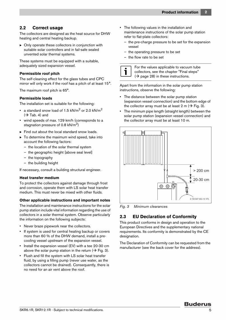
• Install the expansion vessel (EV) with a tee 20-30 cm above the solar pump station in the return ( Fig. 3).
• Flush and fill the system with LS solar heat transfer fluid, by using a filling pump (never use water, as the collectors cannot be drained). Consequently, there is no need for an air vent above the roof.
• The following values in the installation and maintenance instructions of the solar pump station refer to flat-plate collectors:– the pre-charge pressure to be set for the expansion
vessel– the operating pressure to be set– the flow rate to be set
Apart from the information in the solar pump station instructions, observe the following:
• The distance between the solar pump station (expansion vessel connection) and the bottom edge of the collector array must be at least 2 m ( Fig. 3).
• The minimum pipe length (straight length) between the solar pump station (expansion vessel connection) and the collector array must be at least 10 m.
Fig. 3 Minimum clearances
2.3 EU Declaration of ConformityThis product conforms in design and operation to the European Directives and the supplementary national requirements. Its conformity is demonstrated by the CE designation.
The Declaration of Conformity can be requested from the manufacturer (see the back cover for the address).
For the values applicable to vacuum tube collectors, see the chapter "Final steps" ( page 28) in these instructions.
20-30 cm
> 200 cm
6 720 647 042-14.1ITL
SKR6.1R, SKR12.1R - Subject to technical modifications. 5

2 Product information
2.4 Standard deliveryB Check that the delivered material is complete and
undamaged.
2.4.1 Mounting bracket
Fig. 4 Standard delivery, roof connection for tiles
2.4.2 Installation set
Fig. 5 Standard delivery for installation set
2 x SKR6
3 x SKR6
1 x SKR12
Item 1 Mounting bracket 4 6 4
Item 2 M10 nut 4 6 4
Item 3 Washer 4 6 4
Item 4 T-head bolt 4 6 4
Item 5 Screw 8 x 120 12 18 12
Item 6 Wooden support 100 x 150 x 8 mm
12 18 12
Tab. 2 Standard delivery, roof connection for roof tiles subject to number of collectors
6 720 647 042-16.1ITL
4
32
1
56
2 x SKR6
3 x SKR6
1 x SKR12
Item 2 M10 nut 24 36 6
Item 3 Washer 24 36 6
Item 4 T-head bolt 24 36 6
Item 7 Rail L=1300 mm 2 -- --
Item 7 Rail L=1953 mm 2 3 --
Item 7 Rail L=2007 mm -- 2 --
Item 7 Rail L=2022 mm -- -- 2
Item 8 L connector 4 6 --
Item 9 Clamp top/bottom 4 6 2
Tab. 3 Installation set subject to number of collectors
6 720 647 042-17.1ITL
L
4
9
7
8
32
2 x SKR6.13 x SKR6.1
(or 1xSKR6.1 + 1xSKR12.1) 1 x SKR12.1 or 1 x SKR6.1
Standard snow load: max. 1.5 kN/m2 Standard snow load: max. 1.5 kN/m2 Standard snow load: max. 2.0 kN/m2
Tab. 4 Using the rails (Item 7) and maximum standard snow load (dimensions in mm)
1953
1300
1953
2007
20
22
SKR6.1R, SKR12.1R - Subject to technical modifications.6
2 Product information
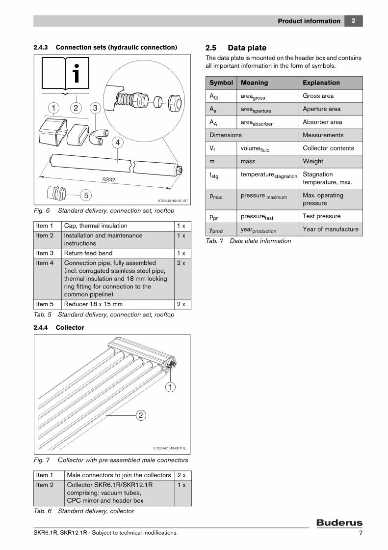
2.4.3 Connection sets (hydraulic connection)
Fig. 6 Standard delivery, connection set, rooftop
2.4.4 Collector
Fig. 7 Collector with pre-assembled male connectors
2.5 Data plateThe data plate is mounted on the header box and contains all important information in the form of symbols.
Item 1 Cap, thermal insulation 1 x
Item 2 Installation and maintenance instructions
1 x
Item 3 Return feed bend 1 x
Item 4 Connection pipe, fully assembled (incl. corrugated stainless steel pipe, thermal insulation and 18 mm locking ring fitting for connection to the common pipeline)
2 x
Item 5 Reducer 18 x 15 mm 2 x
Tab. 5 Standard delivery, connection set, rooftop
Item 1 Male connectors to join the collectors 2 x
Item 2 Collector SKR6.1R/SKR12.1R comprising: vacuum tubes, CPC mirror and header box
1 x
Tab. 6 Standard delivery, collector
6720648182-02.1ST5
6 720 647 042-08.1ITL
Symbol Meaning Explanation
AG areagross Gross area
Aa areaaperture Aperture area
AA areaabsorber Absorber area
Dimensions Measurements
Vf volumefluid Collector contents
m mass Weight
tstg temperaturestagnation Stagnation temperature, max.
pmax pressure maximum Max. operating pressure
ppr pressuretest Test pressure
yprod yearproduction Year of manufacture
Tab. 7 Data plate information
SKR6.1R, SKR12.1R - Subject to technical modifications. 7
3 Regulations
2.6 Specification
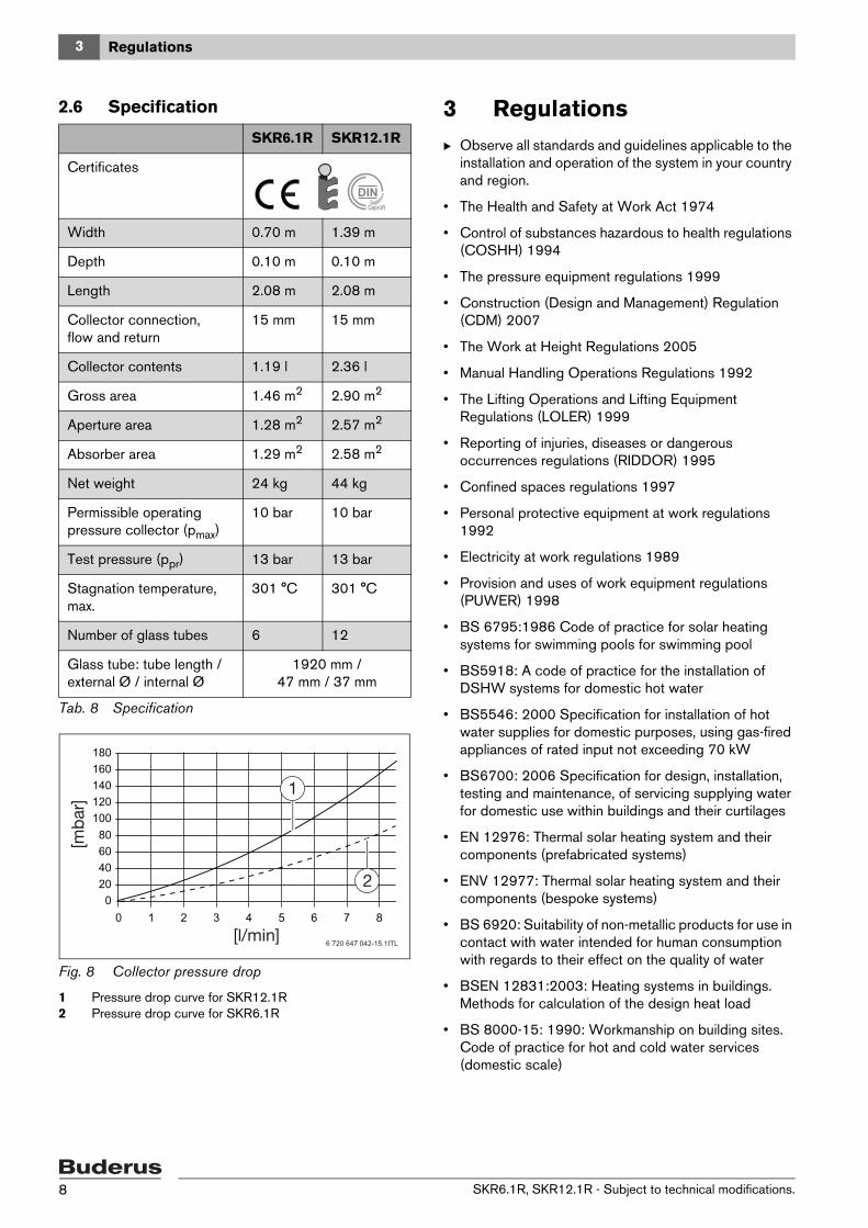
Fig. 8 Collector pressure drop
1 Pressure drop curve for SKR12.1R2 Pressure drop curve for SKR6.1R
3 RegulationsB Observe all standards and guidelines applicable to the
installation and operation of the system in your country and region.
• The Health and Safety at Work Act 1974
• Control of substances hazardous to health regulations (COSHH) 1994
• The pressure equipment regulations 1999
• Construction (Design and Management) Regulation (CDM) 2007
• The Work at Height Regulations 2005
• Manual Handling Operations Regulations 1992
• The Lifting Operations and Lifting Equipment Regulations (LOLER) 1999
• Reporting of injuries, diseases or dangerous occurrences regulations (RIDDOR) 1995
• Confined spaces regulations 1997
• Personal protective equipment at work regulations 1992
• Electricity at work regulations 1989
• Provision and uses of work equipment regulations (PUWER) 1998
• BS 6795:1986 Code of practice for solar heating systems for swimming pools for swimming pool
• BS5918: A code of practice for the installation of DSHW systems for domestic hot water
• BS5546: 2000 Specification for installation of hot water supplies for domestic purposes, using gas-fired appliances of rated input not exceeding 70 kW
• BS6700: 2006 Specification for design, installation, testing and maintenance, of servicing supplying water for domestic use within buildings and their curtilages
• EN 12976: Thermal solar heating system and their components (prefabricated systems)
• ENV 12977: Thermal solar heating system and their components (bespoke systems)
• BS 6920: Suitability of non-metallic products for use in contact with water intended for human consumption with regards to their effect on the quality of water
• BSEN 12831:2003: Heating systems in buildings. Methods for calculation of the design heat load
• BS 8000-15: 1990: Workmanship on building sites. Code of practice for hot and cold water services (domestic scale)
SKR6.1R SKR12.1R
Certificates
Width 0.70 m 1.39 m
Depth 0.10 m 0.10 m
Length 2.08 m 2.08 m
Collector connection, flow and return
15 mm 15 mm
Collector contents 1.19 l 2.36 l
Gross area 1.46 m2 2.90 m2
Aperture area 1.28 m2 2.57 m2
Absorber area 1.29 m2 2.58 m2
Net weight 24 kg 44 kg
Permissible operating pressure collector (pmax)
10 bar 10 bar
Test pressure (ppr) 13 bar 13 bar
Stagnation temperature, max.
301 °C 301 °C
Number of glass tubes 6 12
Glass tube: tube length / external Ø / internal Ø
1920 mm / 47 mm / 37 mm
Tab. 8 Specification
DIN
6 720 647 042-15.1ITL
020406080
100120140160180
0 1 2 3 4 5 6 7 8
SKR6.1R, SKR12.1R - Subject to technical modifications.8
4 Before installation
4 Before installation
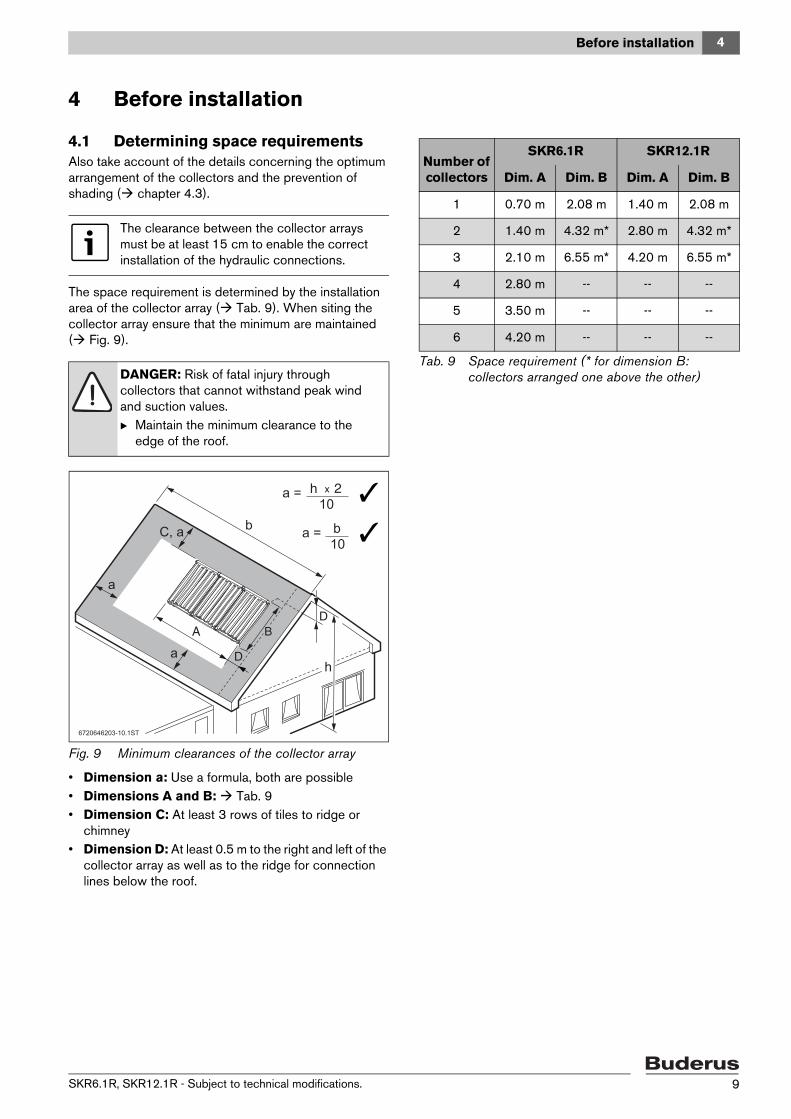
4.1 Determining space requirementsAlso take account of the details concerning the optimum arrangement of the collectors and the prevention of shading ( chapter 4.3).
The space requirement is determined by the installation area of the collector array ( Tab. 9). When siting the collector array ensure that the minimum are maintained ( Fig. 9).
Fig. 9 Minimum clearances of the collector array
• Dimension a: Use a formula, both are possible• Dimensions A and B: Tab. 9• Dimension C: At least 3 rows of tiles to ridge or
chimney• Dimension D: At least 0.5 m to the right and left of the
collector array as well as to the ridge for connection lines below the roof.
The clearance between the collector arrays must be at least 15 cm to enable the correct installation of the hydraulic connections.
DANGER: Risk of fatal injury through collectors that cannot withstand peak wind and suction values. B Maintain the minimum clearance to the
edge of the roof.
6720646203-10.1ST
C, a a = b
10
a =10
bb
h
h
aa
aa
Number of collectors
SKR6.1R SKR12.1R
Dim. A Dim. B Dim. A Dim. B
1 0.70 m 2.08 m 1.40 m 2.08 m
2 1.40 m 4.32 m* 2.80 m 4.32 m*
3 2.10 m 6.55 m* 4.20 m 6.55 m*
4 2.80 m -- -- --
5 3.50 m -- -- --
6 4.20 m -- -- --
Tab. 9 Space requirement (* for dimension B: collectors arranged one above the other)
SKR6.1R, SKR12.1R - Subject to technical modifications. 9

4 Before installation
4.2 Planning the hydraulic connection
Before you install the collectors you will need to know how you can arrange the collectors.
Maximum number of collectors per row:• SKR6.1R: 6 collectors• SKR12.1R: 3 collectors
The following shows two examples of hydraulic layouts for collectors:
Fig. 10 Connection in a single row
1 Collector sensor (always on the connection side)2 Flow pipe (to the cylinder)3 Return pipe (from the cylinder)4 Return U-bend
Fig. 11 Triple row connection (with shut-off valve)
1 Collector sensor (always on the connection side)2 Flow pipe (to the cylinder)3 Return pipe (from the cylinder)4 Shut-off valve (accessory)5 Return U-bend
Please refer to the solar technology technical guide for detailed information on planning the hydraulic system and components.
Fit the collector sensor [1] in the collector connected to the flow and return pipes [2] and [3].
6 720 647 042-03.1ITL
6 720 647 042-04.1ITL
4
1
32
SKR6.1R, SKR12.1R - Subject to technical modifications.10

4 Before installation
4.3 General notes
• Obtain information about on-site conditions and local regulations.
• Remove and replace broken roof tiles, shingles, etc.• Always install collectors with the header box on the top
( Fig. 12).
Fig. 12 Permissible installation orientation
• Arrange collectors on the roof in an appealing pattern, for example, so that the collector array is in line with windows and doors ( Fig. 13). However, observe the minimum clearances towards the edge of the roof for this ( Fig. 9, page 9).
• Align the collector array facing south, wherever possible ( Fig. 13).
Fig. 13 Aligning the collector array to the building's shape
• Avoid shading from adjacent buildings, trees etc. falling onto the collector array ( Fig. 14).
Fig. 14 Avoiding shade
4.4 Required tools and accessories• Power drill • 6 mm, 9 mm drill bits for pre-drilling• Spanner, sizes SW13, 17, 22, 24, 30• Hammer (for roof tiles and connection set)
4.5 Lightning protectionThe requirement for lightning protection can differ from region to region.
B Check regional regulations as to whether a lightning protection system is required.
Lightning protection is frequently required for buildings higher than 20 m.
Lightning protection should be installed by a qualified electrician.
Where there is a lightning protection system installed, check the inclusion of the solar thermal system into this system.
4.6 Installation orderTo secure collectors to the roof, install in the following order:
1. Determine distances for mounting brackets2. Install mounting brackets.3. Install rails and clamps.4. Fit the collectors and collector sensors.5. Connect piping to collectors.
We recommend that you engage the services of a roofing contractor, as they are experienced in working on roofs and dealing with the risk of falling.
6 720 647 042-23.1ITL
6720646203-08.1ST
N
S
W O
6720646203-09.1ST
SKR6.1R, SKR12.1R - Subject to technical modifications. 11
5 Handling
5 HandlingThe collectors and installation materials are heavy and awkward. Observe the following information, as working on the roof involves potential dangers.
B Use the straps at the top of the collector for transport.
B To make handling collectors and installation materials easier, use the following aids. They must have sufficient load bearing capacity:– Site lift or crane– Roofing ladder or equipment for roof access– Lifting belt– Scaffolding
B Dispose of shipping packaging by environmentally responsible means.
DANGER: Risk to life through falling and falling parts!B Do not use a ladder to move components
onto the roof because the installation materials and collectors are heavy and difficult to handle.
B For all work on the roof, take appropriate measures to prevent accidents.
B Secure the roof against parts falling off.B Always wear your own protective clothing
or safety equipment.B The installation on the roof must be
performed by at least 2 people. B During handling and installation, secure
the collectors and installation components against falling.
B After completing installation, check that the installation set and collectors are securely positioned.
WARNING: Risk of injury through glass splinters.B When handling collectors, always wear
safety gloves and goggles.
NOTICE: Collector damage through transport.B We recommend transporting the collector
to the roof in its transportation packaging.
DANGER: Risk to life through inadequately secured collectors during transport. B Ensure the straps are securely tied to the
collectors. B To prevent oscillation, observe the wind
force and guide hanging collectors with guy ropes.
SKR6.1R, SKR12.1R - Subject to technical modifications.12
6 Fitting the mounting bracket
6 Fitting the mounting bracketThe collectors are connected to the structural element using mounting brackets. The distances shown are using the example of the mounting bracket for roof tiles.
B Ensure there is safe access to the roof in compliance with current legislation and health and safety requirements.
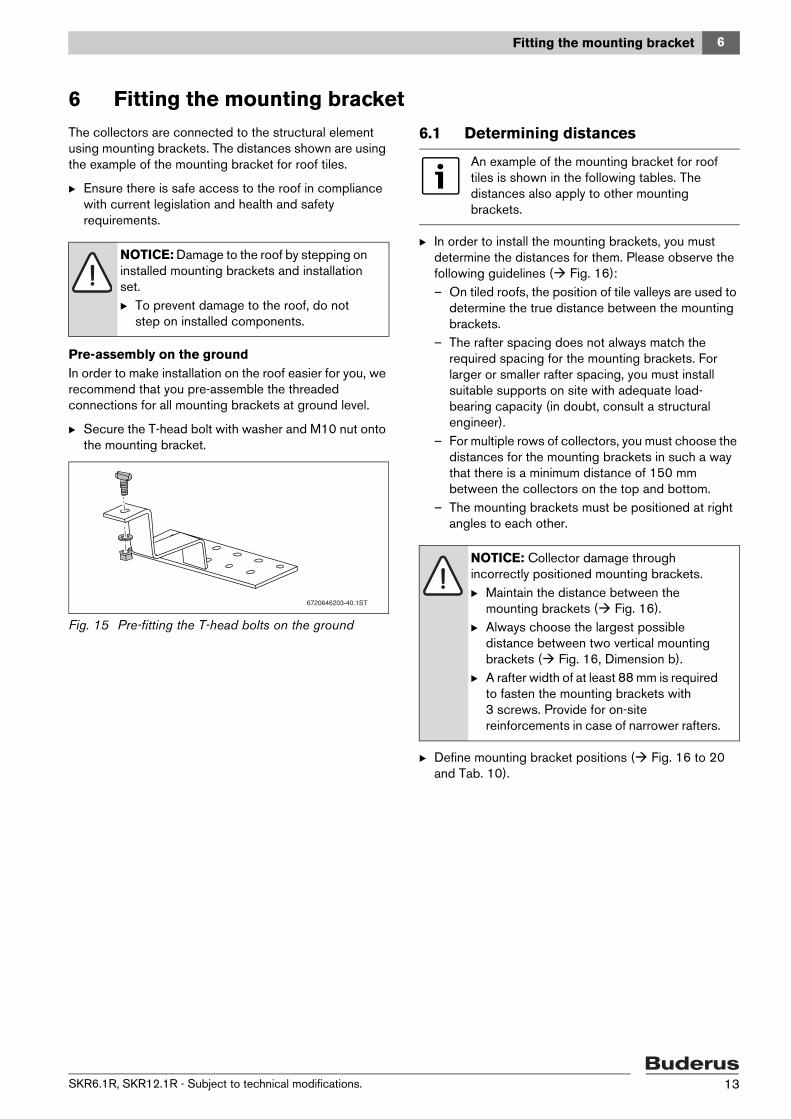
Pre-assembly on the groundIn order to make installation on the roof easier for you, we recommend that you pre-assemble the threaded connections for all mounting brackets at ground level.
B Secure the T-head bolt with washer and M10 nut onto the mounting bracket.
Fig. 15 Pre-fitting the T-head bolts on the ground
6.1 Determining distances
B In order to install the mounting brackets, you must determine the distances for them. Please observe the following guidelines ( Fig. 16):– On tiled roofs, the position of tile valleys are used to
determine the true distance between the mounting brackets.
– The rafter spacing does not always match the required spacing for the mounting brackets. For larger or smaller rafter spacing, you must install suitable supports on site with adequate load-bearing capacity (in doubt, consult a structural engineer).
– For multiple rows of collectors, you must choose the distances for the mounting brackets in such a way that there is a minimum distance of 150 mm between the collectors on the top and bottom.
– The mounting brackets must be positioned at right angles to each other.
B Define mounting bracket positions ( Fig. 16 to 20 and Tab. 10).
NOTICE: Damage to the roof by stepping on installed mounting brackets and installation set.B To prevent damage to the roof, do not
step on installed components.
6720646203-40.1ST
An example of the mounting bracket for roof tiles is shown in the following tables. The distances also apply to other mounting brackets.
NOTICE: Collector damage through incorrectly positioned mounting brackets. B Maintain the distance between the
mounting brackets ( Fig. 16). B Always choose the largest possible
distance between two vertical mounting brackets ( Fig. 16, Dimension b).
B A rafter width of at least 88 mm is required to fasten the mounting brackets with 3 screws. Provide for on-site reinforcements in case of narrower rafters.
SKR6.1R, SKR12.1R - Subject to technical modifications. 13
6 Fitting the mounting bracket
6.1.1 Vertical distances for the mounting brackets
Fig. 16 Distances to be maintained and rafter width
6.1.2 Horizontal distances for the mounting brackets
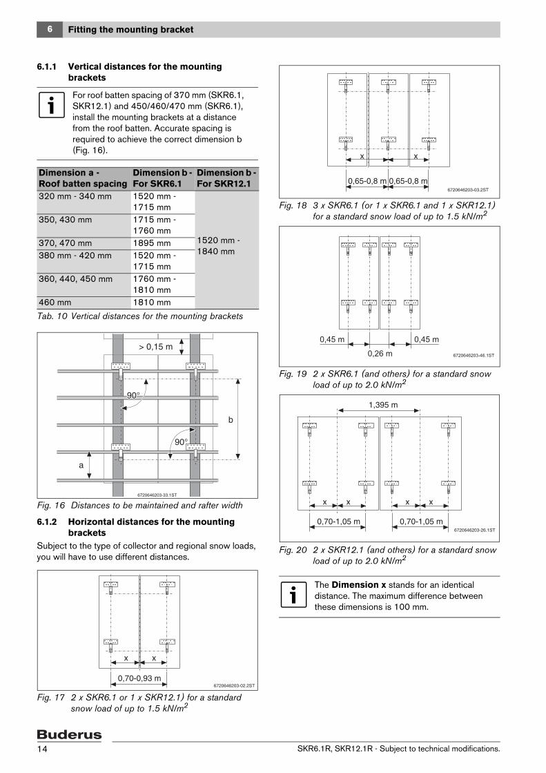
Subject to the type of collector and regional snow loads, you will have to use different distances.
Fig. 17 2 x SKR6.1 or 1 x SKR12.1) for a standard snow load of up to 1.5 kN/m2
Fig. 18 3 x SKR6.1 (or 1 x SKR6.1 and 1 x SKR12.1) for a standard snow load of up to 1.5 kN/m2
Fig. 19 2 x SKR6.1 (and others) for a standard snow load of up to 2.0 kN/m2
Fig. 20 2 x SKR12.1 (and others) for a standard snow load of up to 2.0 kN/m2
For roof batten spacing of 370 mm (SKR6.1, SKR12.1) and 450/460/470 mm (SKR6.1), install the mounting brackets at a distance from the roof batten. Accurate spacing is required to achieve the correct dimension b (Fig. 16).
Dimension a - Roof batten spacing
Dimension b - For SKR6.1
Dimension b - For SKR12.1
320 mm - 340 mm 1520 mm - 1715 mm
1520 mm - 1840 mm
350, 430 mm 1715 mm - 1760 mm
370, 470 mm 1895 mm380 mm - 420 mm 1520 mm -
1715 mm360, 440, 450 mm 1760 mm -
1810 mm460 mm 1810 mm
Tab. 10 Vertical distances for the mounting brackets
6720646203-33.1ST
b
> 0,15 m
a
90°90°
90°90°
6720646203-02.2ST0,70-0,93 m
xx
The Dimension x stands for an identical distance. The maximum difference between these dimensions is 100 mm.
6720646203-03.2ST
0,65-0,8 m 0,65-0,8 m
x x
6720646203-46.1ST
0,45 m
0,26 m
0,45 m
6720646203-26.1ST
0,70-1,05 m
1,395 m
x x
0,70-1,05 m
x x
SKR6.1R, SKR12.1R - Subject to technical modifications.14

6 Fitting the mounting bracket
6.2 Installing mounting brackets on roof tile roofs
B Depending on the distances ( page 14), remove 2-3 roof tiles from a row in the area of the rafters.
B Position the mounting bracket:– The mounting bracket must be in the tile valley.– The mounting bracket must be installed directly
above the roof tile below it without touching this tile.
B Mark the mounting bracket positions on the roof. B Place mounting bracket [1] on rafter and pre-drill using
a 6 mm drill bit. Fasten with the screws [3].
B If required, use wooden spacer [5] for height compensation (pre-drill 9 mm).
B Carefully remove the roof tiles' drip edges and profiles [2] and [4] in the area of the mounting brackets.
B Screw mounting bracket with 3 screws 8 x 120 mm [3] onto the rafter. Use a SW13 spanner for tightening.
B Put the roof tiles back on.
Fig. 21 Mounting brackets for roof tile roofs
1 Mounting bracket2 Top roof tile3 Screws 8 x 120 mm4 Bottom roof tile5 Wooden spacer 100 x 150 x 8 mm
NOTICE: Roof leaks from fine, wind-driven snow in the area of the mounting bracket.B If there is a larger gap between the top
and the bottom roof tiles, close this gap using UV-resistant sealant.
6720646203-07.1ST
1.
3.2.
2
4
3
1
5
13 6 9
SKR6.1R, SKR12.1R - Subject to technical modifications. 15

6 Fitting the mounting bracket
6.3 Installing mounting brackets on plain tile roofs
B Depending on the distances determined ( page 14) remove 2-3 plain tiles from a row in the area of the rafters.
B Position the mounting bracket:– The mounting bracket [1] must be installed in the
middle of the plain tile below.– The mounting bracket must be installed directly
above the plan tile below it without touching this tile.
B To make room for the mounting bracket, shorten the plain tile at the top edge if necessary and/or make a create a suitable fixing point to the roof.
B Mark the mounting bracket positions on the roof. B Pre-drill rafter with 6 mm drill bit. B If required, use wooden spacer [4] supplied for height
compensation (pre-drill 9 mm).B Screw mounting bracket with 3 screws 8 x 120 mm [2]
onto the rafter. Use a SW13 spanner.B Cut adjacent plain tiles [3] and re-install them.
Fig. 22 Mounting brackets for plain tile roofs
1 Mounting bracket2 Screws 8 x 120 mm3 Plain tiles, trimmed4 Wooden spacer 100 x 150 x 8 mm
NOTICE: Roof leaks on plain tile roofs!B Consult a roofing contractor for advice
and assistance.
NOTICE: Roof leaks from fine, wind-driven snow in the area of the mounting bracket.B If there is a larger gap between the top
and the bottom roof tiles, close this gap using UV-resistant sealant.
6720646203-11.1ST
2.
3.
3
1.1
4
13 6 9
2
SKR6.1R, SKR12.1R - Subject to technical modifications.16
6 Fitting the mounting bracket
6.4 Installing mounting brackets on roofs with monk/nun tiles
B Depending on the distances determined ( page 14), remove 2-3 roof tiles from a row in the area of the rafters.
B Position the mounting bracket:– The mounting bracket must be installed in the
middle of the roof tile below.– The mounting bracket must be installed directly
above the roof tile below it without touching this tile.
B Mark the mounting bracket positions on the roof.
B If required, use wooden spacer [3] supplied for height compensation (pre-drill 9 mm).
B Screw mounting bracket [1] with 3 screws 8 x 120 mm [2] onto the rafter. Use a SW13 spanner.
B Re-install the roof tiles.
Fig. 23 Mounting brackets on roofs with monk/nun tiles
1 Mounting bracket2 Screws 8 x 120 mm3 Wooden spacer 100 x 150 x 8 mm
NOTICE: Roof leaks from fine, wind-driven snow in the area of the mounting bracket.B If there is a larger gap between the top
and the bottom roof tiles, close this gap using UV-resistant sealant.
6720646203-12.1ST
1 2
3
13 6 9
SKR6.1R, SKR12.1R - Subject to technical modifications. 17

6 Fitting the mounting bracket
6.5 Installing mounting brackets on slate roofs
B Depending on the distances determined ( page 14), remove sufficient slates in the area of the rafters.
B Position the mounting bracket:– The mounting bracket must be installed directly
above the slate below it without touching this panel. B Mark the mounting bracket positions on the roof. B Screw mounting bracket [2] with 3 screws 8 x 120 mm
[1] onto the rafter. Use a SW13 spanner. B Re-install slates.
Fig. 24 Mounting brackets for slate shingle roofs
1 Screws 8 x 120 mm2 Mounting bracket
NOTICE: To avoid roof leaks on slate or shingle roofs, consult a roofer for advice and assistance.B A competent person must carry out the
installation. B Because the mounting bracket can rest on
the panel below, this panel must be reinforced on-site using a suitable material.
6720646203-17.1ST
1
2
13 6
SKR6.1R, SKR12.1R - Subject to technical modifications.18
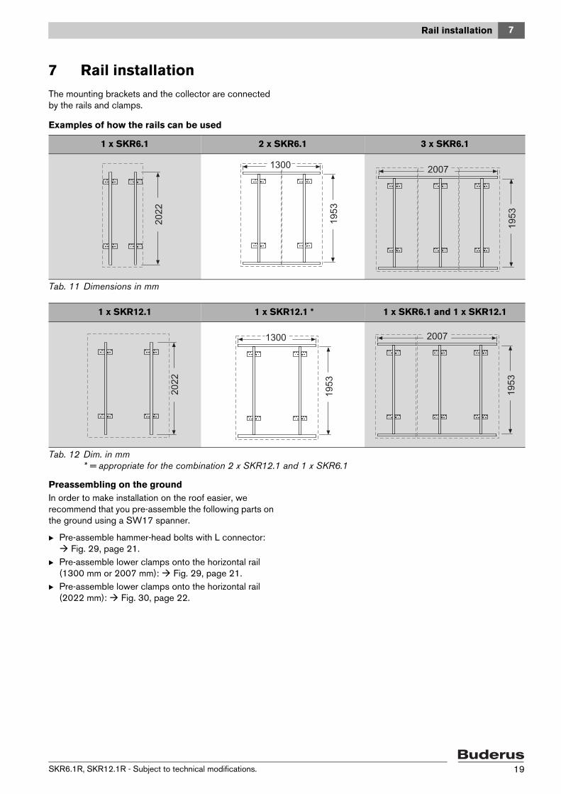
7 Rail installation
7 Rail installationThe mounting brackets and the collector are connected by the rails and clamps.
Examples of how the rails can be used
Preassembling on the groundIn order to make installation on the roof easier, we recommend that you pre-assemble the following parts on the ground using a SW17 spanner.
B Pre-assemble hammer-head bolts with L connector: Fig. 29, page 21.
B Pre-assemble lower clamps onto the horizontal rail (1300 mm or 2007 mm): Fig. 29, page 21.
B Pre-assemble lower clamps onto the horizontal rail (2022 mm): Fig. 30, page 22.
1 x SKR6.1 2 x SKR6.1 3 x SKR6.1
Tab. 11 Dimensions in mm
1 x SKR12.1 1 x SKR12.1 * 1 x SKR6.1 and 1 x SKR12.1
Tab. 12 Dim. in mm* = appropriate for the combination 2 x SKR12.1 and 1 x SKR6.1
20
22
19
53
1300
1953
20072
02
2
19
53
13001300
1953
2007
SKR6.1R, SKR12.1R - Subject to technical modifications. 19
7 Rail installation
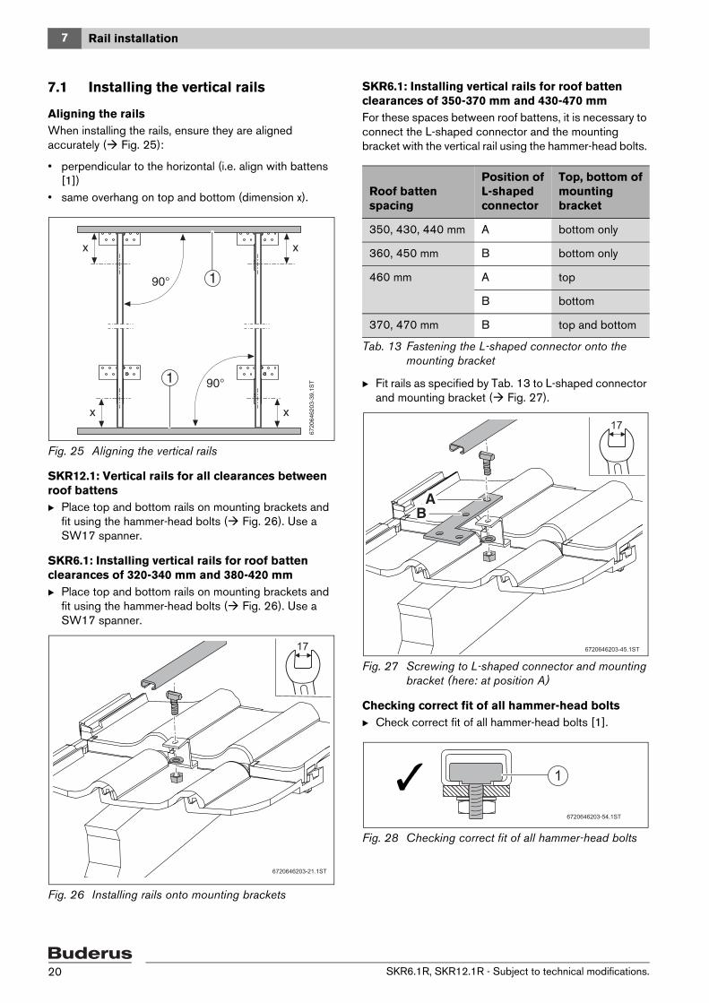
7.1 Installing the vertical rails
Aligning the railsWhen installing the rails, ensure they are aligned accurately ( Fig. 25):
• perpendicular to the horizontal (i.e. align with battens [1])
• same overhang on top and bottom (dimension x).
Fig. 25 Aligning the vertical rails
SKR12.1: Vertical rails for all clearances between roof battensB Place top and bottom rails on mounting brackets and
fit using the hammer-head bolts ( Fig. 26). Use a SW17 spanner.
SKR6.1: Installing vertical rails for roof batten clearances of 320-340 mm and 380-420 mmB Place top and bottom rails on mounting brackets and
fit using the hammer-head bolts ( Fig. 26). Use a SW17 spanner.
Fig. 26 Installing rails onto mounting brackets
SKR6.1: Installing vertical rails for roof batten clearances of 350-370 mm and 430-470 mmFor these spaces between roof battens, it is necessary to connect the L-shaped connector and the mounting bracket with the vertical rail using the hammer-head bolts.
B Fit rails as specified by Tab. 13 to L-shaped connector and mounting bracket ( Fig. 27).
Fig. 27 Screwing to L-shaped connector and mounting bracket (here: at position A)
Checking correct fit of all hammer-head boltsB Check correct fit of all hammer-head bolts [1].
Fig. 28 Checking correct fit of all hammer-head bolts
6720646203-21.1ST
17
Roof batten spacing
Position of L-shaped connector
Top, bottom of mounting bracket
350, 430, 440 mm A bottom only
360, 450 mm B bottom only
460 mm A top
B bottom
370, 470 mm B top and bottom
Tab. 13 Fastening the L-shaped connector onto the mounting bracket
6720646203-45.1ST
AABB
17
6720646203-54.1ST
1
SKR6.1R, SKR12.1R - Subject to technical modifications.20

7 Rail installation
7.2 Installing horizontal rails and clamps
Pre-assembly of lower clamping brackets on the groundB Split the top and bottom clamping [2] and [1] at their
pre-determined breaking point. B Install the lower clamps [1] onto the bottom rail at the
distances indicated ( Fig. 29) and fit them using a nut and a washer. Use a SW17 spanner.
Do not fasten the upper clamps [2] onto the collector and the top rail until after the collector has been installed.
Installing the railsWhen installing the rails, ensure they are aligned accurately (dimension x: same overhang on the right and left Fig. 29).
Ensure that the hammer-head bolt is installed correctly [4].B Using the L-shaped connector [5], 4 hammer-head
bolts, 4 washers and 4 nuts, install the horizontal rail [6] onto the vertical rail [7].
Fig. 29 Rails and clips, all dimensions in mm
1 Lower clamp2 Upper clamps3 Horizontal rail 2007 mm4 Hammer-head bolt (fitted) 5 L-shaped connector for connecting the rails6 Horizontal rail7 Vertical rail
Horizontal rails are not required in all cases ( Tab. 11 and 12, page 19).
450-55020-90 160-
260
1953
6720646203-19.2ST
5
7
6
90°
90°
1
2
1
450-550 20-90
90°x x
17
4
450-55020-90 160-
260
450-550 20-90160-
260
450-550
2007
1300
3
SKR6.1R, SKR12.1R - Subject to technical modifications. 21
7 Rail installation
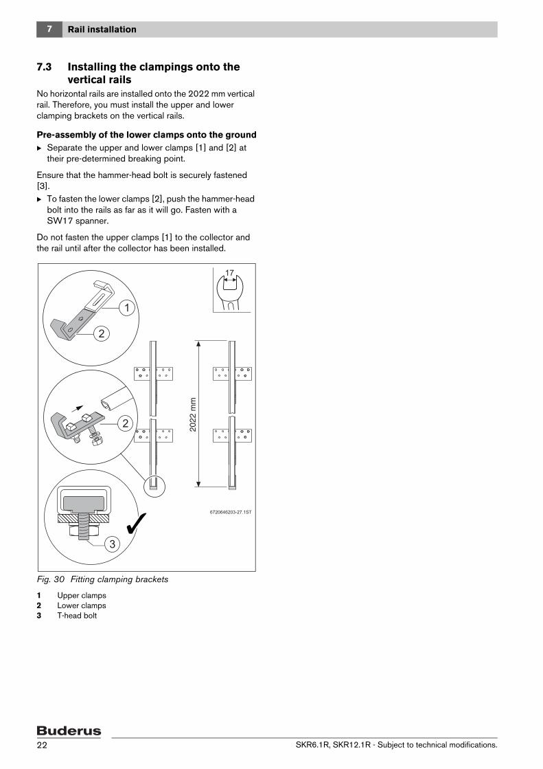
7.3 Installing the clampings onto the vertical rails
No horizontal rails are installed onto the 2022 mm vertical rail. Therefore, you must install the upper and lower clamping brackets on the vertical rails.
Pre-assembly of the lower clamps onto the groundB Separate the upper and lower clamps [1] and [2] at
their pre-determined breaking point.
Ensure that the hammer-head bolt is securely fastened [3].B To fasten the lower clamps [2], push the hammer-head
bolt into the rails as far as it will go. Fasten with a SW17 spanner.
Do not fasten the upper clamps [1] to the collector and the rail until after the collector has been installed.
Fig. 30 Fitting clamping brackets
1 Upper clamps2 Lower clamps3 T-head bolt
6720646203-27.1ST
1
2
17
2 2022
mm
3
SKR6.1R, SKR12.1R - Subject to technical modifications.22
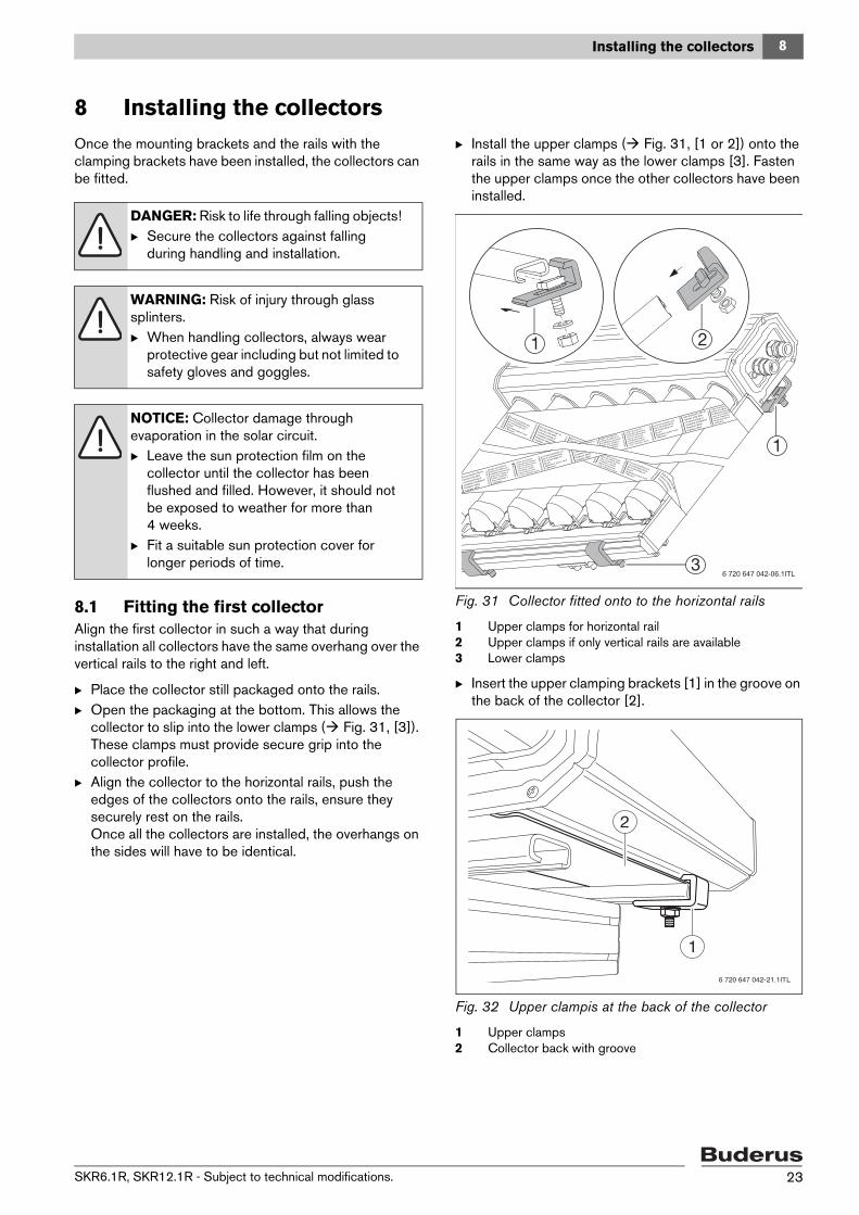
8 Installing the collectors
8 Installing the collectorsOnce the mounting brackets and the rails with the clamping brackets have been installed, the collectors can be fitted.
8.1 Fitting the first collectorAlign the first collector in such a way that during installation all collectors have the same overhang over the vertical rails to the right and left.
B Place the collector still packaged onto the rails. B Open the packaging at the bottom. This allows the
collector to slip into the lower clamps ( Fig. 31, [3]). These clamps must provide secure grip into the collector profile.
B Align the collector to the horizontal rails, push the edges of the collectors onto the rails, ensure they securely rest on the rails.Once all the collectors are installed, the overhangs on the sides will have to be identical.
B Install the upper clamps ( Fig. 31, [1 or 2]) onto the rails in the same way as the lower clamps [3]. Fasten the upper clamps once the other collectors have been installed.
Fig. 31 Collector fitted onto to the horizontal rails
1 Upper clamps for horizontal rail2 Upper clamps if only vertical rails are available3 Lower clamps
B Insert the upper clamping brackets [1] in the groove on the back of the collector [2].
Fig. 32 Upper clampis at the back of the collector
1 Upper clamps 2 Collector back with groove
DANGER: Risk to life through falling objects!B Secure the collectors against falling
during handling and installation.
WARNING: Risk of injury through glass splinters.B When handling collectors, always wear
protective gear including but not limited to safety gloves and goggles.
NOTICE: Collector damage through evaporation in the solar circuit. B Leave the sun protection film on the
collector until the collector has been flushed and filled. However, it should not be exposed to weather for more than 4 weeks.
B Fit a suitable sun protection cover for longer periods of time.
6 720 647 042-06.1ITL
1
2
6 720 647 042-21.1ITL
SKR6.1R, SKR12.1R - Subject to technical modifications. 23
8 Installing the collectors
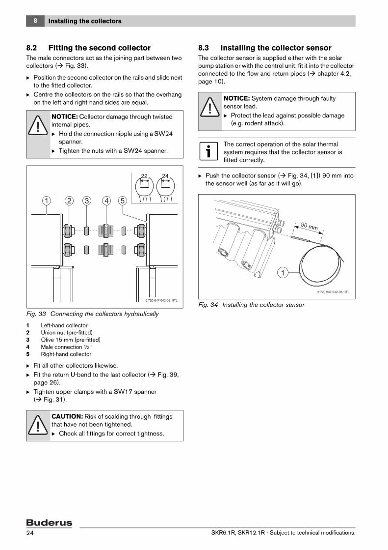
8.2 Fitting the second collectorThe male connectors act as the joining part between two collectors ( Fig. 33).
B Position the second collector on the rails and slide next to the fitted collector.
B Centre the collectors on the rails so that the overhang on the left and right hand sides are equal.
Fig. 33 Connecting the collectors hydraulically
1 Left-hand collector2 Union nut (pre-fitted)3 Olive 15 mm (pre-fitted) 4 Male connection ½ “5 Right-hand collector
B Fit all other collectors likewise.B Fit the return U-bend to the last collector ( Fig. 39,
page 26).B Tighten upper clamps with a SW17 spanner
( Fig. 31).
8.3 Installing the collector sensorThe collector sensor is supplied either with the solar pump station or with the control unit; fit it into the collector connected to the flow and return pipes ( chapter 4.2, page 10).
B Push the collector sensor ( Fig. 34, [1]) 90 mm into the sensor well (as far as it will go).
Fig. 34 Installing the collector sensor
NOTICE: Collector damage through twisted internal pipes.B Hold the connection nipple using a SW24
spanner. B Tighten the nuts with a SW24 spanner.
CAUTION: Risk of scalding through fittings that have not been tightened.B Check all fittings for correct tightness.
6 720 647 042-09.1ITL
NOTICE: System damage through faulty sensor lead. B Protect the lead against possible damage
(e.g. rodent attack).
The correct operation of the solar thermal system requires that the collector sensor is fitted correctly.
6 720 647 042-05.1ITL
90 mm
SKR6.1R, SKR12.1R - Subject to technical modifications.24

8 Installing the collectors
8.4 Fitting the bridging set (accessory)To improve the appearance of the space between two collectors, the bridging set can be fitted as an accessory.
Standard delivery• 1 x thermal insulation (45 mm wide) with self-adhesive
closure• 1 x cover panel• 2 x connection plugs with metal pin
InstallationThe installation requires the collectors to be aligned precisely. 1. Place the thermal insulation over both fittings from
below and seal using the self-adhesive tab.2. Push on the cover panel from above and lock in place
at the back of the header boxes.
Fig. 35 Top of collector at header box: installing thermal insulation and cover panel
The plug that is part of the bridging set holds both collector frames together with the correct clearance. 1. Remove the original plugs from the collector frame
profiles. 2. Insert the new connection plugs into the profiles.3. Drive the metal pin with a hammer into the side of the
plug.
Fig. 36 Collector bottom: replacing the plugs
6 720 647 042-13.1ITL
6720646203-42.1ST
1.
2. 3.
SKR6.1R, SKR12.1R - Subject to technical modifications. 25
9 Hydraulic connection
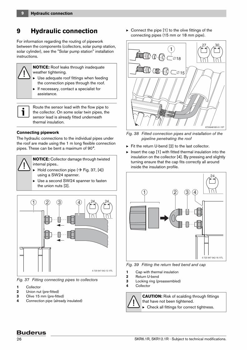
9 Hydraulic connectionFor information regarding the routing of pipework between the components (collectors, solar pump station, solar cylinder), see the "Solar pump station" installation instructions.
Connecting pipeworkThe hydraulic connections to the individual pipes under the roof are made using the 1 m long flexible connection pipes. These can be bent a maximum of 90°.
Fig. 37 Fitting connecting pipes to collectors
1 Collector2 Union nut (pre-fitted)3 Olive 15 mm (pre-fitted)4 Connection pipe (already insulated)
B Connect the pipe [1] to the olive fittings of the connecting pipes (15 mm or 18 mm pipe).
Fig. 38 Fitted connection pipes and installation of the pipeline penetrating the roof
B Fit the return U-bend [2] to the last collector.B Insert the cap [1] with fitted thermal insulation into the
insulation on the collector [4]. By pressing and slightly turning ensure that the cap fits correctly all around inside the insulation profile.
Fig. 39 Fitting the return feed bend and cap
1 Cap with thermal insulation2 Return U-bend3 Locking ring (preassembled)4 Collector
NOTICE: Roof leaks through inadequate weather tightening. B Use adequate roof fittings when feeding
the connection pipes through the roof.B If necessary, contact a specialist for
assistance.
Route the sensor lead with the flow pipe to the collector. On some solar twin pipes, the sensor lead is already fitted underneath thermal insulation.
NOTICE: Collector damage through twisted internal pipes..B Hold connection pipe ( Fig. 37, [4])
using a SW24 spanner.B Use a second SW24 spanner to fasten
the union nuts [2].
24 24
6 720 647 042-12.1ITL
CAUTION: Risk of scalding through fittings that have not been tightened. B Check all fittings for correct tightness.
18
15
6720648182-01.1ST
3027
6 720 647 042-18.1ITL
42 31
SKR6.1R, SKR12.1R - Subject to technical modifications.26
9 Hydraulic connection
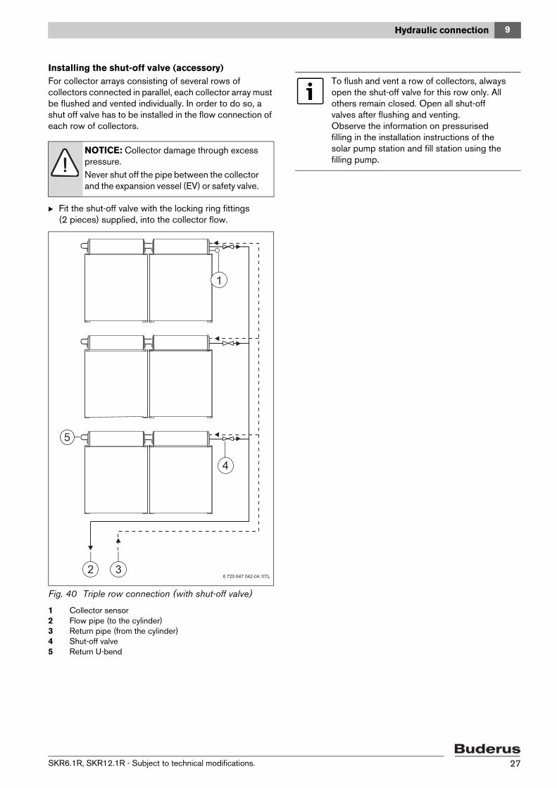
Installing the shut-off valve (accessory)For collector arrays consisting of several rows of collectors connected in parallel, each collector array must be flushed and vented individually. In order to do so, a shut off valve has to be installed in the flow connection of each row of collectors.
B Fit the shut-off valve with the locking ring fittings (2 pieces) supplied, into the collector flow.
Fig. 40 Triple row connection (with shut-off valve)
1 Collector sensor2 Flow pipe (to the cylinder)3 Return pipe (from the cylinder)4 Shut-off valve5 Return U-bend
NOTICE: Collector damage through excess pressure.Never shut off the pipe between the collector and the expansion vessel (EV) or safety valve.
6 720 647 042-04.1ITL
4
1
32
To flush and vent a row of collectors, always open the shut-off valve for this row only. All others remain closed. Open all shut-off valves after flushing and venting. Observe the information on pressurised filling in the installation instructions of the solar pump station and fill station using the filling pump.
SKR6.1R, SKR12.1R - Subject to technical modifications. 27
10 Final steps
10 Final steps
10.1 Checking the installation
10.2 Pressure filling, flushing, ventingThe solar thermal system must be filled by means of pressure filling, then flushed and vented. Observe the notes on pressure filling in the installation instructions for the solar pump station as well as the filling station.
10.3 Adjusting the pre-charge pressure of the expansion vessel
Prior to filling the solar thermal system, check the expansion vessel pre-charge pressure (air side).
B If required, correct the expansion vessel pre-charge pressure.
10.4 Determining and setting the operating pressure
Following the pressurised filling and flushing as well as a pressure test, determine and set the required operating pressure. For information on how to proceed, please refer to the instructions for the solar pump station.
10.5 Adjusting the flow rate
10.6 Insulating piping
On-site thermal insulation for pipeworkB Outdoors, use UV and high temperature-resistant
thermal insulation.B Use insulation and pipe clips resistant to high
temperatures for indoor piping. B Make the insulation bird-proof.
Final steps can only be carried out after the following checks have been made.
Checks
1. Are all connection fittings tightened?
2. Are all threaded fittings on rails, mounting brackets and clamps tightened?
3. Has the collector sensor been pushed into the sensor well as far as it will go (90 mm)?
Tab. 14 Checking the installation
NOTICE: Collector damage through frost.B Fill solar heat transfer medium LS under
pressure for filling and flushing the system. Never use water, as the collectors cannot be drained.
The expansion vessel pre-charge pressure is calculated from the static system head plus 1.7 bar (static system head = difference in head between the expansion vessel connection and the top edge of the collector; 1 metre difference in head corresponds to 0.1 bar). Example: 10 m height differential equals 1.0 bar plus 1.7 bar = 2.7 bar.
The operating pressure is calculated from the static system head plus 2.0 bar (static system head = difference in head between the expansion vessel connection and the top edge of the collector; 1 metre difference in head corresponds to 0.1 bar). Example: 10 m height differential equals 1.0 bar plus 2.0 bar = 3.0 bar.
Observe the information in the installation and maintenance instructions for the solar pump station ( chapter "Adjusting the flow rate").
Flow rate l/min (at a flow temperature 20 °C)
Number of collectorsSKR6.1R (l/min)
SKR12.1R (l/min)
1 -- 2.0
2 2.0 4.0
3 3.0 5.5
4 4.0 --
5 4.5 --
6 5.5 --
Tab. 15 Flow rate to be set for solar controllers without speed control, subject to the number and type of collectors
SKR6.1R, SKR12.1R - Subject to technical modifications.28

11 Replacing individual tubes
11 Replacing individual tubesYou can recognise a faulty tube by the fact that the silver coating in the lower section of the tube has changed to a white mist.
Fig. 41 Replacing individual tubes
1 Silicone ring2 Tube holder3 Release lever4 Tube
Removing a mechanically damaged tubeB Carefully remove glass splinters without damaging the
CPC mirror surface. B Remove the bottom tube retainer [2].
Removing a mechanically undamaged tubeB In order to be able to remove the bottom tube retainer
[2],– push the tube 5 mm upwards into the header box
and – push down the two release levers [3] on the right
and left using your thumb and index finger.B Release the tube retainer by lifting towards the header
box.B Lift the tube slightly and turn it about the longitudinal
axis to pull it straight down and out.
Fitting a tubeInstall the new tube [4] in reverse order to the removal of the old one.
Ensure the silicon ring [1] sits correctly inside the header box.B Coat the top of the tube with a soapy solution or
lubricating paste.B Push the tube through the silicon ring into the header
box whilst turning it slightly. B Place the tube holder [2] on the end of the tube, push
it in between the notches in the aluminium profile and engage it in the groove.
B Pull down the tube into the tube holder as far as it will go.
WARNING: Risk of injury through glass splinters.B When handling collectors, always wear
safety gloves and goggles.
If there is inadequate room to remove the tube, the coil can be bent upwards up to 20°.
6 720 647 042-10.1ITL
SKR6.1R, SKR12.1R - Subject to technical modifications. 29

12 Environmental protection/disposal
12 Environmental protection/disposal
Environmental protection is one of our principal policies.
Quality of performance, efficiency and environmental protection are equally important objectives for us. Statutory and other regulations concerning environmental protection are strictly applied. To protect the environment, we use the best possible technology and materials.
DisposalAt the end of their service life, materials should be recycled using the most environmentally responsible processes.
SKR6.1R, SKR12.1R - Subject to technical modifications.30
13 Maintenance/inspection
13 Maintenance/inspectionThe collector array must be checked at regular intervals (inspection). Defects/faults must be remedied without delay (maintenance). We recommend conducting the first maintenance/inspection after about 500 hours run, and then at intervals of 1-2 years.
Use the table as a copy template so that you will have documentation available even after the third maintenance.
B Fill out the report and tick off the tasks performed.
DANGER: Risk to life through falls and falling parts!B For all work on the roof, take appropriate
measures to prevent accidents.B Secure the roof against falls.B Always wear your own protective clothing
or safety equipment.
Owner: Site location:
Maintenance and inspection tasks Page Maintenance/inspection
Date
1. Visual inspection of the collectors carried out (correct seating of glass tubes, visual impression)?
2. Collector sensor is positioned correctly and is inserted into the sensor well as far as it will go?
24
3. Visual inspection of the installation system carried out?
4. Visual inspection for leaks carried out at points where the mounting system meets the roof?
5. Visual inspection of pipe insulation carried out?
Notes
The collector array has been serviced as specified by these instructions.
Date, stamp, signature
Date, stamp, signature
Date, stamp, signature
Tab. 16 Inspection and service report
SKR6.1R, SKR12.1R - Subject to technical modifications. 31

�������
���������� ������ ������������������������������������������ �������!!���������������
���"#������"��"�$
%�� �&'���%( )���������#���������*)��� � ������� ����+�,��"