installation and servicing instructions - buderus, uk … · · 2011-03-03– installation and...
TRANSCRIPT
Installation and servicing instructions
For qualified profes-sionals
Please read carefully prior to commission-ing and servicing
Programming unitRC35
7 74
7 00
6 34
1 �
12/2
006
GB

Contents
Contents
Contents 2
1 Safety instructions and symbols 41.1 Safety instructions and explanation of symbols . . . . . . . . . . . . . . 41.2 Explanation of symbols . . . . . . . . . . . . . . . . . . . . . . . . . . . 6
2 Information about the product 62.1 Correct use . . . . . . . . . . . . . . . . . . . . . . . . . . . . . . . . . 62.2 EU Declaration of Conformity . . . . . . . . . . . . . . . . . . . . . . . . 62.3 Included in delivery . . . . . . . . . . . . . . . . . . . . . . . . . . . . . 62.4 Specifications . . . . . . . . . . . . . . . . . . . . . . . . . . . . . . . . 72.5 Validity of these instructions for function modules (accessories) . . . . . 82.6 Accessories . . . . . . . . . . . . . . . . . . . . . . . . . . . . . . . . . 8
3 Installation 93.1 Choosing the right installation position . . . . . . . . . . . . . . . . . . 9
3.1.1 Installation in reference room . . . . . . . . . . . . . . . . . . . . 93.1.2 Installation on boiler . . . . . . . . . . . . . . . . . . . . . . . . 10
3.2 Types of installation . . . . . . . . . . . . . . . . . . . . . . . . . . . . 103.3 Installation and connection . . . . . . . . . . . . . . . . . . . . . . . . 113.4 Attaching or removing the programming unit . . . . . . . . . . . . . . 12
4 Operating basics 134.1 Overview of operation . . . . . . . . . . . . . . . . . . . . . . . . . . 134.2 Introduction to the Service menu . . . . . . . . . . . . . . . . . . . . . 144.3 Overview of the Service menu . . . . . . . . . . . . . . . . . . . . . . 16
5 Commissioning 175.1 General commissioning . . . . . . . . . . . . . . . . . . . . . . . . . . 175.2 Checklist: important parameters for commissioning . . . . . . . . . . . 185.3 Quick commissioning (Quick operation menu) . . . . . . . . . . . . . 195.4 Detailed commissioning . . . . . . . . . . . . . . . . . . . . . . . . . 205.5 System handover . . . . . . . . . . . . . . . . . . . . . . . . . . . . . 205.6 Shut-down / switching off . . . . . . . . . . . . . . . . . . . . . . . . 215.7 Operating tips . . . . . . . . . . . . . . . . . . . . . . . . . . . . . . . 21
RC35 programming unit - Technical specifications are subject to change without prior notice.2
Contents
6 Entering system settings (Service menu – Settings) 226.1 System data . . . . . . . . . . . . . . . . . . . . . . . . . . . . . . . . 22
6.1.1 Building type ("damping" of outside temperature) . . . . . . . . 236.1.2 Minimum ("lowest expected") outside temperature . . . . . . . . 24
6.2 Boiler data . . . . . . . . . . . . . . . . . . . . . . . . . . . . . . . . . 256.3 Heating circuit data . . . . . . . . . . . . . . . . . . . . . . . . . . . . 26
6.3.1 Assignment of programming unit / remote controlunit in the software . . . . . . . . . . . . . . . . . . . . . . . . . 30
6.3.2 Control mode (outside temp. controlled / room influence) . . . . 306.3.3 Heating characteristics . . . . . . . . . . . . . . . . . . . . . . . 316.3.4 Reduction modes (night setback) . . . . . . . . . . . . . . . . . 326.3.5 Frost protection . . . . . . . . . . . . . . . . . . . . . . . . . . . 33
6.4 Domestic hot water (DHW) . . . . . . . . . . . . . . . . . . . . . . . . 356.5 Solar data (not with UBA1.x) . . . . . . . . . . . . . . . . . . . . . . . 376.6 RC35 calibration . . . . . . . . . . . . . . . . . . . . . . . . . . . . . . 386.7 Contact data . . . . . . . . . . . . . . . . . . . . . . . . . . . . . . . . 39
7 Diagnosis 407.1 Function test (not with UBA1.x) . . . . . . . . . . . . . . . . . . . . . . 407.2 Monitor value . . . . . . . . . . . . . . . . . . . . . . . . . . . . . . . . 417.3 Error message . . . . . . . . . . . . . . . . . . . . . . . . . . . . . . . 427.4 Htg. charact. curve . . . . . . . . . . . . . . . . . . . . . . . . . . . . . 427.5 Versions . . . . . . . . . . . . . . . . . . . . . . . . . . . . . . . . . . 42
8 Servicing 43
9 Reset 44
10 Troubleshooting 45
Index 51
RC35 programming unit - Technical specifications are subject to change without prior notice. 3
Safety instructions and symbols1
1 Safety instructions and symbols
1.1 Safety instructions and explanation of symbols
Installation and commissioning
Observe all instructions to ensure satisfactory operation.
Installation and commissioning must only be carried out by qualified system installers.
Use
Always use this device correctly and in conjunction with the stated control systems.
This device must not be used with control systems using the UBA-H3 controller.
Observe all regulations and standards applicable to installation and operation of the system in your country.
Read and observe the safety information and instructions:
Risk of death from electric shock
The electrical supply must be connected by a qualified electrician. The terminal diagram must be followed.
Before installation: isolate all poles of the power supply (230 V AC). Undertake meas-ures to prevent power from being switched back on unintentionally.
Do not install this device in rooms with high moisture exposure (e.g. bathrooms, sau-nas).
Never connect this device to the 230 V power mains.
Warning: frost
The heating system can freeze up in cold weather, if switched off.
Leave the heating system permanently switched on.
Switch on frost protection.
In the event of a fault: remedy the fault immediately.
RC35 programming unit - Technical specifications are subject to change without prior notice.4

Safety instructions and symbols 1
1.2 Explanation of symbols
The terms indicate the seriousness of the ensuing risk if measures for minimising damage are not taken.
– Caution means that minor property damage may occur.
– Warning means that minor injury or severe property damage may occur.
– Danger means that severe injury may occur. Very serious cases may result in death.
Notes contain important information for situations in which there is no risk to the user or the device.
Display text: Words appearing on the display are shown in bold in the text.
Example: USER MENU
Action sequences: Each step in an action sequence is marked with a bullet point.
Example: Press .
If action sequences have more than two steps and the order of the steps is important, they are numbered (1., 2., ...).
Safety instructions throughout the text are indicated by a warning triangle in-side a rectangular frame.
Notes throughout the text are identified with this symbol. They are bounded by horizontal lines above and below the text.
Note on using this manual: Section 4.2 "Introduction to the Service menu" explains in detail the steps needed for programming all the settings in the Serv-ice menu. In the sections which come after it, programming is only explained in outline.
standard displayoperation modesswitching programmesum./win. threshold
USER MENU
RC35 programming unit - Technical specifications are subject to change without prior notice. 5

Information about the product2
2 Information about the product
2.1 Correct use
The RC35 programming unit must only be used to operate and control Buderus heating systems in residential buildings.
The boiler must be equipped with EMS (energy management system) or UBA1.x (univer-sal burner control).
The programming unit must not be used in conjunction with Logamatic 2000/4000 con-trol panels.
We recommend that the heating system is always operated with a programming unit (only emergency operation is possible without a programming unit).
If RC20 remote control units manufactured before 2006 are being used, only two remote control units can be connected. If you have any questions about this, please contact your local Buderus office.
2.2 EU Declaration of Conformity
2.3 Included in delivery
– RC35 programming unit
– Operating instructions
– Installation and servicing instructions
– Wall bracket, mounting materials
The design and operation of this product conforms to European Directives and the supplementary national requirements. Its conformity is confirmed by the CE marking. You can view the Declaration of Conformity on the internet at www.buderus.de/konfo or request a copy from your local Buderus office.
RC35 programming unit - Technical specifications are subject to change without prior notice.6

Information about the product 2
2.4 Specifications
Temperature sensor characteristics
When measuring temperature sensor resistance, observe the following requirements:
– Isolate the system before measuring.
– Measure the resistance at the cable ends.
– The resistances represent mean values and are subject to tolerances.
Unit RC35Power supply via bus system V 16 V DCPower consumption W 0.3Power consumption with backlighting W 0.6Dimensions (width/height/depth) mm 150/90/32Weight g 233Operating temperature °C 0 to +50Storage temperature °C 0 to +70Relative humidity % 0 to 90CE marking
Table 1 Specifications for the RC35 programming unit
Outside temperature sensor
Boiler/flow temperature sensor
DHW temperature sensor°C kΩ °C kΩ °C kΩ-20 96.358 10 19.872 60 2.49-15 72.51 16 15.699 65 2.084-10 55.054 20 12.488 70 1.753-5 42.162 25 10.001 75 1.481±0 32.556 30 8.060 80 1.2565 25.339 35 6.535 85 1.07010 19.872 40 5.331 90 0.91515 15.699 45 4.372 95 0.78620 12.488 50 3.606 100 0.67725 10.001 55 2.98930 8.060
Table 2 Resistances of the temperature sensors, for EMS only
RC35 programming unit - Technical specifications are subject to change without prior notice. 7

Information about the product2
2.5 Validity of these instructions for function modules (accesso-ries)
These instructions also apply to the programming unit when used in conjunction with the MM10 mixer module and the WM10 low loss header module.
If the heating system is equipped with other function modules (e.g. SM10 solar module), you will find additional setting options in some menus. These are described in separate instructions.
2.6 Accessories
For precise information regarding suitable accessories, refer to the catalogue.
– MM10 mixer module1 for controlling a three-way mixing valve. The instructions for the MM10 form part of the RC35 instructions.
– WM10 low loss header module1 for operating a hydraulic separator
– Solar module and other EMS modules (e.g. ASM10 connection module)1
– Remote control unit1 (e.g. RC20/RC20RF) for controlling a particular heating circuit
– Outside temperature sensor, external room temperature sensor
1) The use of modules is not possible with boilers with UBA1.x and DBA.
RC35 programming unit - Technical specifications are subject to change without prior notice.8

Installation 3
3 Installation
3.1 Choosing the right installation position
3.1.1 Installation in reference room
If the system is room-temperature controlled, the following requirements must be observed:
– Installation position on an internal wall (Fig. 1)
– Maintain the specified distance from the door(s) (to avoid draughts).
– Allow clearance below the programming unit (Fig. 1, shaded area) (to ensure correct temperature measurement).
– The reference room (= installation room) must be as representative as possible of the entire home. External heat sources in the reference room (like sunlight or other heat sources such as an open fire) affect the control's function. This means it may be too cold in rooms without external heat sources.
– The thermostatic valves on the radiators in the reference room must always stay fully open so that the two temperature controls do not affect one another.
Fig. 1 Minimum clearances for installation in a reference room
If there is no suitable reference room, we recommend setting the system to out-side temperature control instead (this requires an outside sensor). Alternatively you could install an external room sensor in the room with the greatest heating requirements (e.g. living room).
RC35 programming unit - Technical specifications are subject to change without prior notice. 9
Installation3
3.1.2 Installation on boiler
The unit can be installed directly on boilers equipped with EMS (Energy Management Sys-tem).
The outside temperature sensor for outside temperature control is not delivered as stand-ard, but can be ordered as an accessory.
3.2 Types of installation
The programming unit can be installed in three different ways:
– As the only programming unit in the system (factory setting): the programming unit is mounted in a room in the home (the reference room) or on the boiler. Example: detached house with one heating circuit.
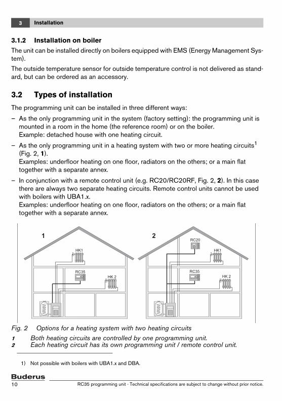
– As the only programming unit in a heating system with two or more heating circuits1 (Fig. 2, 1).Examples: underfloor heating on one floor, radiators on the others; or a main flat together with a separate annex.
– In conjunction with a remote control unit (e.g. RC20/RC20RF, Fig. 2, 2). In this case there are always two separate heating circuits. Remote control units cannot be used with boilers with UBA1.x.Examples: underfloor heating on one floor, radiators on the others; or a main flat together with a separate annex.
Fig. 2 Options for a heating system with two heating circuits1 Both heating circuits are controlled by one programming unit.2 Each heating circuit has its own programming unit / remote control unit.
1) Not possible with boilers with UBA1.x and DBA.
RC35 programming unit - Technical specifications are subject to change without prior notice.10
Installation 3
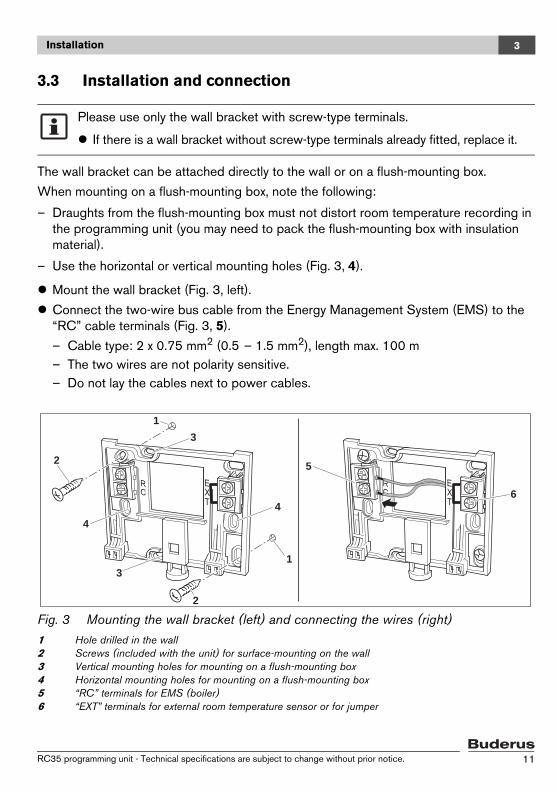
3.3 Installation and connection
The wall bracket can be attached directly to the wall or on a flush-mounting box.
When mounting on a flush-mounting box, note the following:
– Draughts from the flush-mounting box must not distort room temperature recording in the programming unit (you may need to pack the flush-mounting box with insulation material).
– Use the horizontal or vertical mounting holes (Fig. 3, 4).
Mount the wall bracket (Fig. 3, left).
Connect the two-wire bus cable from the Energy Management System (EMS) to the “RC” cable terminals (Fig. 3, 5).
– Cable type: 2 x 0.75 mm2 (0.5 – 1.5 mm2), length max. 100 m– The two wires are not polarity sensitive.– Do not lay the cables next to power cables.
Fig. 3 Mounting the wall bracket (left) and connecting the wires (right)1 Hole drilled in the wall2 Screws (included with the unit) for surface-mounting on the wall3 Vertical mounting holes for mounting on a flush-mounting box4 Horizontal mounting holes for mounting on a flush-mounting box5 “RC” terminals for EMS (boiler)6 “EXT” terminals for external room temperature sensor or for jumper
Please use only the wall bracket with screw-type terminals.
If there is a wall bracket without screw-type terminals already fitted, replace it.
1
2
3
4
3
4
1
2
5
6
RC35 programming unit - Technical specifications are subject to change without prior notice. 11

Installation3
If the RC35 is operated without an external room sensor, a jumper is required on the “EXT”terminals (Fig. 3, 6) (the jumper is factory fitted).
If the RC35 is operated with an external room sensor, the factory-fitted jumper on “EXT” must be removed and the external room sensor must be connected there instead.
3.4 Attaching or removing the programming unit
Attaching the programming unit
Hook the top of the programming unit onto the mounting plate in the direction shown by the arrows (Fig. 4, A1).
Push the bottom of the programming unit against the mounting plate in the direction shown by the arrow until it clicks into place (Fig. 4, A2).
Removing the programming unit
Press the button on the underside of the mounting plate in the direction shown by the arrow (Fig. 4, B1) and pull the programming unit forward at the same time (Fig. 4, B2).
Remove the programming unit by lifting upward (Fig. 4, B3).
Fig. 4 Attaching the programming unit (left) or removing it (right)
1
2
1
2
1
A B3
RC35 programming unit - Technical specifications are subject to change without prior notice.12
Operating basics 4
4 Operating basics
4.1 Overview of operation
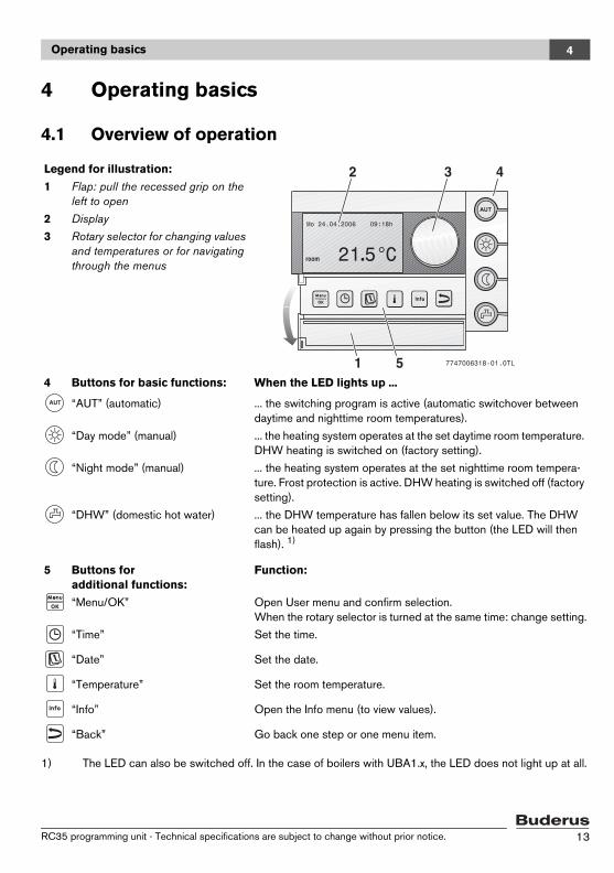
Legend for illustration:
1 Flap: pull the recessed grip on the left to open
2 Display
3 Rotary selector for changing values and temperatures or for navigating through the menus
4 Buttons for basic functions: When the LED lights up ...
“AUT” (automatic) ... the switching program is active (automatic switchover between daytime and nighttime room temperatures).
“Day mode” (manual) ... the heating system operates at the set daytime room temperature. DHW heating is switched on (factory setting).
“Night mode” (manual) ... the heating system operates at the set nighttime room tempera-ture. Frost protection is active. DHW heating is switched off (factory setting).
“DHW” (domestic hot water) ... the DHW temperature has fallen below its set value. The DHW can be heated up again by pressing the button (the LED will then flash). 1)
1) The LED can also be switched off. In the case of boilers with UBA1.x, the LED does not light up at all.
5 Buttons for additional functions:
Function:
“Menu/OK” Open User menu and confirm selection. When the rotary selector is turned at the same time: change setting.
“Time” Set the time.
“Date” Set the date.
“Temperature” Set the room temperature.
“Info” Open the Info menu (to view values).
“Back” Go back one step or one menu item.
RC35 programming unit - Technical specifications are subject to change without prior notice. 13

Operating basics4
4.2 Introduction to the Service menu
The SERVICE MENU to set the parameters for the system. The Service menu also con-tains fault functions diagnosis, for maintenance purposes, and performing a reset. The procedure for operation is always the same:
1. Open the flap (by pulling the recessed grip on the left).
2. Press the buttons + + at the same time to open the SERVICE MENU.
3. Turn the rotary selector to change the selected item (marked with B).
4. Press to select the marked item.
5. To change the value, hold down the button (the value starts flashing) and turn the rotary selector at the same time.Release the button: the modified value is saved.
6. Press to go back one step.
-or-
Press several times or shut the flap to return to the default display.
Example: Setting the building type ("delay" time)
Operation Result
1. Open the flap (by pulling the recessed grip on the left).
2. Press the buttons + + at the same time to open the SERVICE MENU.
3. Turn the rotary selector anti-clockwise until settings is selected (marked with B).
Table 3 How to use the Service menu (example)
Fr 02.12.2005 10:20houtside temp. -1°C
21.5°C
SERVICE MENU
Bquick operationsettingsdiagnosisservicing
SERVICE MENU
quick operationsettingsdiagnosisservicing
B
RC35 programming unit - Technical specifications are subject to change without prior notice.14

Operating basics 4
4. Press to confirm the selection.
The SERVICE\SETTINGS menu is opened.
5. Turn the rotary selector anti-clockwise until boiler data is selected (marked with B).
Press to select boiler data.
6. To change the value, hold down the button (the value starts flashing) and turn the rotary selector at the same time.
7. Release the button .
The value stops flashing. The modified value is saved.
8. If you have carried out this example as practice only, make sure that the original setting is retained.
To do so, repeat steps 6 and 7 if necessary.
9. Press to go back one step.
-or-
To finish entering settings, press several times or shut the flap.
The default display re-appears.
You can enter all settings in the SERVICE MENU using this procedure.
Operation Result
Table 3 How to use the Service menu (example)
SERVICE\SETTINGS
Bplant databoiler datadomestic hot waterheating circuit 1
SETTINGS\BOILERWhat type of buildingdo you have?
medium
SETTINGS\BOILERWhat type of buildingdo you have?
medium
SETTINGS\BOILERWhat type of buildingdo you have?
light
SETTINGS\BOILERWhat type of buildingdo you have?
medium
RC35 programming unit - Technical specifications are subject to change without prior notice. 15
Operating basics4
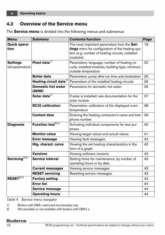
4.3 Overview of the Service menu
The Service menu is divided into the following menus and submenus:
Menu Submenu Contents/function PageQuick opera-tion
The most important parameters from the Set-tings menu for configuration of the heating sys-tem (e.g. number of heating circuits, installed modules)
19
Settings (all parameters)
Plant data1)
1) Boilers with DBA: restricted functionality only.
Parameters: language, number of heating cir-cuits, installed modules, building type, minimum outside temperature
22
Boiler data Parameters: pump after-run time and modulation 25Heating circuit data1) Parameters of the installed heating circuits 26Domestic hot water (DHW)
Parameters for domestic hot water 35
Solar data1) If solar is installed: see documentation for the solar module
37
RC35 calibration Parameters: calibration of the displayed room temperature
38
Contact data Entering the heating contractor's name and tele-phone number
39
Diagnosis Function test2)1)
2) Not possible or not available with boilers with UBA1.x.
Activating individual components for test pur-poses
40
Monitor value Viewing target values and actual values 41Error message Viewing fault messages 42Htg. charact. curve Viewing the set heating characteristics in the
form of a graph42
Versions Viewing software versions 42Servicing2)1) Service interval Setting times for maintenance, by number of
operating hours or by date43
Current messages Viewing service messages 43RESET servicing Resetting service messages 43
RESET2)1) Factory setting 44Error list 44Service message 44Operating hours 44
Table 4 Service menu navigator
RC35 programming unit - Technical specifications are subject to change without prior notice.16
Commissioning 5
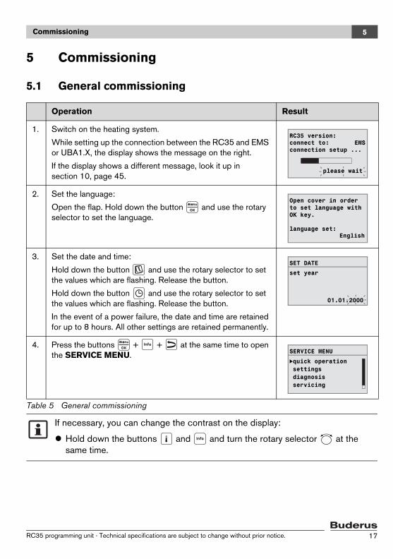
5 Commissioning
5.1 General commissioning
Operation Result
1. Switch on the heating system.
While setting up the connection between the RC35 and EMS or UBA1.X, the display shows the message on the right.
If the display shows a different message, look it up in section 10, page 45.
2. Set the language:
Open the flap. Hold down the button and use the rotary selector to set the language.
3. Set the date and time:
Hold down the button and use the rotary selector to set the values which are flashing. Release the button.
Hold down the button and use the rotary selector to set the values which are flashing. Release the button.
In the event of a power failure, the date and time are retained for up to 8 hours. All other settings are retained permanently.
4. Press the buttons + + at the same time to open the SERVICE MENU.
Table 5 General commissioning
If necessary, you can change the contrast on the display:
Hold down the buttons and and turn the rotary selector at the same time.
RC35 version:connect to: EMSconnection setup ...
please wait
Open cover in orderto set language withOK key.
language set:English
SET DATE
set year
01.01.2000
SERVICE MENU
Bquick operationsettingsdiagnosisservicing
RC35 programming unit - Technical specifications are subject to change without prior notice. 17
Commissioning5
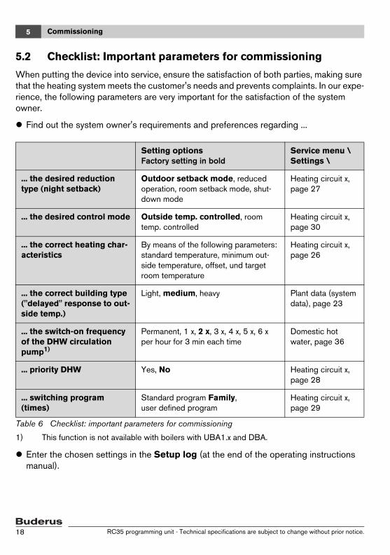
5.2 Checklist: Important parameters for commissioning
When putting the device into service, ensure the satisfaction of both parties, making sure that the heating system meets the customer's needs and prevents complaints. In our expe-rience, the following parameters are very important for the satisfaction of the system owner.
Find out the system owner's requirements and preferences regarding ...
Enter the chosen settings in the Setup log (at the end of the operating instructions manual).
Setting optionsFactory setting in bold
Service menu \ Settings \
... the desired reduction type (night setback)
Outdoor setback mode, reduced operation, room setback mode, shut-down mode
Heating circuit x, page 27
... the desired control mode Outside temp. controlled, room temp. controlled
Heating circuit x, page 30
... the correct heating char-acteristics
By means of the following parameters: standard temperature, minimum out-side temperature, offset, und target room temperature
Heating circuit x, page 26
... the correct building type ("delayed" response to out-side temp.)
Light, medium, heavy Plant data (system data), page 23
... the switch-on frequency of the DHW circulation pump1)
1) This function is not available with boilers with UBA1.x and DBA.
Permanent, 1 x, 2 x, 3 x, 4 x, 5 x, 6 x per hour for 3 min each time
Domestic hot water, page 36
... priority DHW Yes, No Heating circuit x, page 28
... switching program (times)
Standard program Family, user defined program
Heating circuit x, page 29
Table 6 Checklist: important parameters for commissioning
RC35 programming unit - Technical specifications are subject to change without prior notice.18

Commissioning 5
5.3 Quick commissioning (Quick operation menu)
Press to open the quick operation menu.
SHORTCUT\ Menu item
Input range Factory setting in bold Other information
BASIC SETUP Which language should be used?
German ...
HYDR. SEP. Have you installed a module for the hydraulic separator?
Yes, No 1)
PLANT Is heating circuit 1 installed (unmixed heating circuit)?
Yes, No
NO. OF MIXERS How many mixed heating circuits are installed?
00 to 3
Set the address on the rotary encoder on the mixer module (factory setting: HC2).1)
HTG. CIRC. 1
(and other heating circuits)
Which operating unit is assigned to heat-ing circuit 1?
RC20/RC20RF, RC35
None
To assign programming units to heating circuits, see page 30. For general heating circuit data, see page 26. Set any other heating circuits in the same way as for heat-ing circuit 1.
How should heating circuit 1 be control-led?
Outside temp. con-trolled,
room temp. controlled
Which heating sys-tem does heating circuit 1 have?
Radiator, convector, floor
For heating characteristics, see page 31
Table 7 Quick operation menu navigator
SERVICE MENU
Bquick operationsettingsdiagnosisservicing
RC35 programming unit - Technical specifications are subject to change without prior notice. 19
Commissioning5
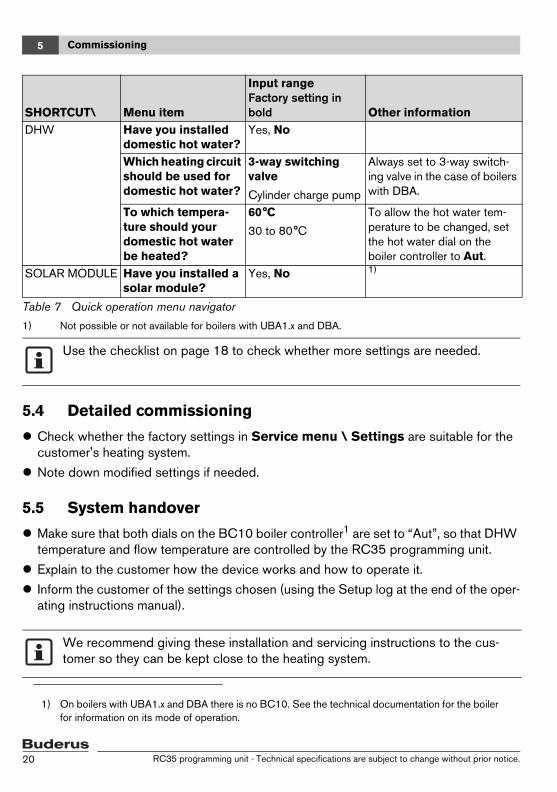
5.4 Detailed commissioning
Check whether the factory settings in Service menu \ Settings are suitable for the customer's heating system.
Note down modified settings if needed.
5.5 System handover
Make sure that both dials on the BC10 boiler controller1 are set to “Aut”, so that DHW temperature and flow temperature are controlled by the RC35 programming unit.
Explain to the customer how the device works and how to operate it.
Inform the customer of the settings chosen (using the Setup log at the end of the oper-ating instructions manual).
DHW Have you installed domestic hot water?
Yes, No
Which heating circuit should be used for domestic hot water?
3-way switching valve
Cylinder charge pump
Always set to 3-way switch-ing valve in the case of boilers with DBA.
To which tempera-ture should your domestic hot water be heated?
60°C
30 to 80°C
To allow the hot water tem-perature to be changed, set the hot water dial on the boiler controller to Aut.
SOLAR MODULE Have you installed a solar module?
Yes, No 1)
1) Not possible or not available for boilers with UBA1.x and DBA.
Use the checklist on page 18 to check whether more settings are needed.
1) On boilers with UBA1.x and DBA there is no BC10. See the technical documentation for the boiler for information on its mode of operation.
We recommend giving these installation and servicing instructions to the cus-tomer so they can be kept close to the heating system.
SHORTCUT\ Menu item
Input range Factory setting in bold Other information
Table 7 Quick operation menu navigator
RC35 programming unit - Technical specifications are subject to change without prior notice.20

Commissioning 5
5.6 Shut-down / switching off
The RC35 programming unit is supplied with power via the heating system and is perma-nently switched on. It is only switched off if the heating system is switched off, such as for maintenance purposes.
To switch the heating system on or off: set the ON/OFF switch on the boiler to position 1 (ON) or 0 (OFF).
5.7 Operating tips
Devices on the EMS bus
In a bus system, only one device can carry out the calculations for a heating circuit. Therefore only one RC35 can be installed in a heating system. If additional room control-lers are required (such as the RC20), they must be installed as remote control units1 with a set heating circuit address (page 26).
Thermostatic radiator valves in the reference room
Thermostatic valves on radiators in the reference room2 are not required for room temper-ature control. If there are thermostatic radiator valves in the reference room, they must be fully open.
Pump anti-seize3
In all operating modes, all heating circuit pumps are switched on for 10 seconds every Wednesday at 12 noon to prevent pump damage. The mixers are then set to "OPEN" for 10 seconds. After 10 seconds, all pumps and mixers then return to their normal, regulated operation.
After switching the unit off or in the event of a power failure, the date and time are retained for up to 8 hours. All other settings are retained permanently.
1) This function is not available for boilers with DBA.2) Room in which an RC35 or RC20/RC20RF is installed3) This function is not available with boilers with UBA1.x and DBA.
RC35 programming unit - Technical specifications are subject to change without prior notice. 21
Entering system settings (Service menu – Settings)6
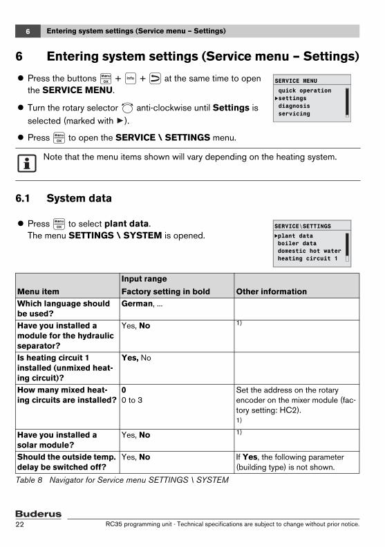
6 Entering system settings (Service menu – Settings)
6.1 System data
Press the buttons + + at the same time to open the SERVICE MENU.
Turn the rotary selector anti-clockwise until Settings is selected (marked with ).
Press to open the SERVICE \ SETTINGS menu.
Note that the menu items shown will vary depending on the heating system.
Press to select plant data.The menu SETTINGS \ SYSTEM is opened.
Menu item
Input range
Factory setting in bold Other informationWhich language should be used?
German, ...
Have you installed a module for the hydraulic separator?
Yes, No 1)
Is heating circuit 1 installed (unmixed heat-ing circuit)?
Yes, No
How many mixed heat-ing circuits are installed?
0 0 to 3
Set the address on the rotary encoder on the mixer module (fac-tory setting: HC2).1)
Have you installed a solar module?
Yes, No 1)
Should the outside temp. delay be switched off?
Yes, No If Yes, the following parameter (building type) is not shown.
Table 8 Navigator for Service menu SETTINGS \ SYSTEM
SERVICE MENU
quick operationsettingsdiagnosisservicing
B
SERVICE\SETTINGS
Bplant databoiler datadomestic hot waterheating circuit 1
RC35 programming unit - Technical specifications are subject to change without prior notice.22
Entering system settings (Service menu – Settings) 6
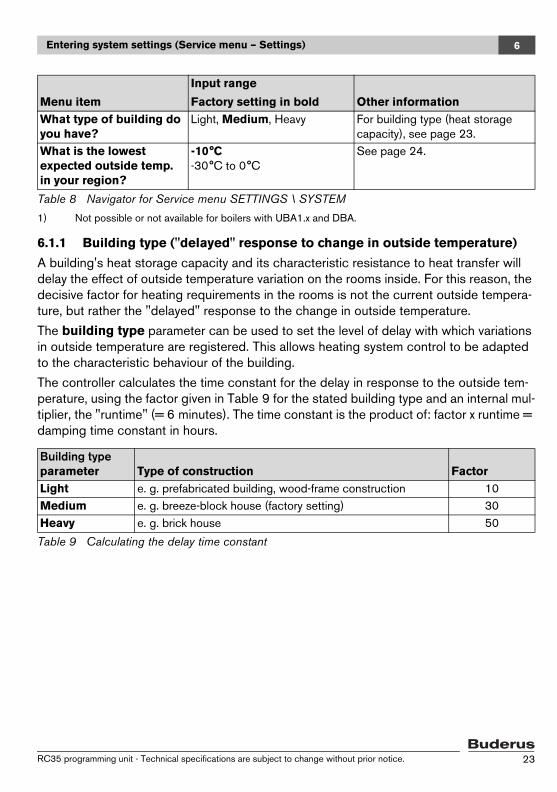
6.1.1 Building type ("delayed" response to change in outside temperature)
A building's heat storage capacity and its characteristic resistance to heat transfer will delay the effect of outside temperature variation on the rooms inside. For this reason, the decisive factor for heating requirements in the rooms is not the current outside tempera-ture, but rather the "delayed" response to the change in outside temperature.
The building type parameter can be used to set the level of delay with which variations in outside temperature are registered. This allows heating system control to be adapted to the characteristic behaviour of the building.
The controller calculates the time constant for the delay in response to the outside tem-perature, using the factor given in Table 9 for the stated building type and an internal mul-tiplier, the "runtime" (= 6 minutes). The time constant is the product of: factor x runtime = damping time constant in hours.
What type of building do you have?
Light, Medium, Heavy For building type (heat storage capacity), see page 23.
What is the lowest expected outside temp. in your region?
-10°C -30°C to 0°C
See page 24.
1) Not possible or not available for boilers with UBA1.x and DBA.
Building type parameter Type of construction FactorLight e. g. prefabricated building, wood-frame construction 10Medium e. g. breeze-block house (factory setting) 30Heavy e. g. brick house 50
Table 9 Calculating the delay time constant
Menu item
Input range
Factory setting in bold Other information
Table 8 Navigator for Service menu SETTINGS \ SYSTEM
RC35 programming unit - Technical specifications are subject to change without prior notice. 23

Entering system settings (Service menu – Settings)6
Example:
Fig. 5 This greatly simplified example shows how the delayed response to outside temperature follows the outside temperature, but does not reach its extreme val-ues.
1 Current outside temperature2 Delayed response to outside temperature
6.1.2 Minimum ("lowest expected") outside temperature
The "lowest expected outside temperature" is the mean of all the coldest outside temper-atures of recent years, and helps to determine the heating characteristics. The value can be taken from the heat requirement calculation which should be done for every building, or from the climatic zone chart for your region.
With the factory setting, changes in the outside temperature will affect the cal-culations for outside-temperature-based control after a delay of no more than three hours (30 x 6 minutes = 180 minutes).
To monitor the calculated, delayed response to outside temperature and the currently recorded outside temperature: open the menu Diagnosis \ Mon-itor value \ Boiler/burner .
RC35 programming unit - Technical specifications are subject to change without prior notice.24

Entering system settings (Service menu – Settings) 6
6.2 Boiler data
Turn the rotary selector anti-clockwise until boiler data is selected (marked with ).
Press to select boiler data.The menu SETTINGS \ BOILER is opened.
Menu itemInput range Factory setting in bold Other information
Boiler pump after-run time after burner stops?
5 min
Deactivated, 1 to 60 min
Setting only possible with boilers with internal boiler pump.1)
1) Not possible or not available with boilers with UBA1.x.
Which settings do you wish to have for the mod-ulating pump?
20 to 8
Characteristics of the boiler pump, depending on KIM/BIM
– 0: if a hydraulic separator (low loss header) has been installed.
– 1-8: see boiler documentation
1) 2)
2) System-dependent
Table 10 Navigator for Service menu SETTINGS \ BOILER
SERVICE\SETTINGS
Bplant databoiler datadomestic hot waterheating circuit 1
RC35 programming unit - Technical specifications are subject to change without prior notice. 25
Entering system settings (Service menu – Settings)6
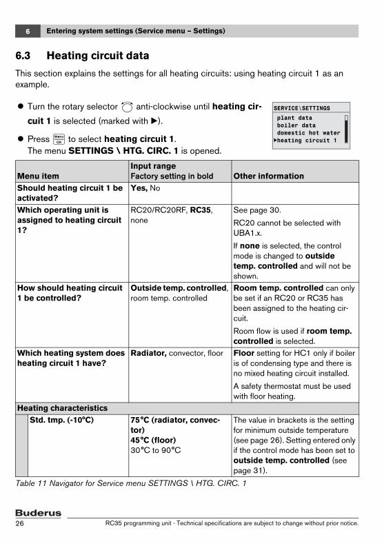
6.3 Heating circuit data
This section explains the settings for all heating circuits: using heating circuit 1 as an example.
Turn the rotary selector anti-clockwise until heating cir-
cuit 1 is selected (marked with B).
Press to select heating circuit 1.The menu SETTINGS \ HTG. CIRC. 1 is opened.
Menu itemInput range Factory setting in bold Other information
Should heating circuit 1 be activated?
Yes, No
Which operating unit is assigned to heating circuit 1?
RC20/RC20RF, RC35, none
See page 30.
RC20 cannot be selected with UBA1.x.
If none is selected, the control mode is changed to outside temp. controlled and will not be shown.
How should heating circuit 1 be controlled?
Outside temp. controlled, room temp. controlled
Room temp. controlled can only be set if an RC20 or RC35 has been assigned to the heating cir-cuit.
Room flow is used if room temp. controlled is selected.
Which heating system does heating circuit 1 have?
Radiator, convector, floor Floor setting for HC1 only if boiler is of condensing type and there is no mixed heating circuit installed.
A safety thermostat must be used with floor heating.
Heating characteristicsStd. tmp. (-10°C) 75°C (radiator, convec-
tor)45°C (floor)30°C to 90°C
The value in brackets is the setting for minimum outside temperature (see page 26). Setting entered only if the control mode has been set to outside temp. controlled (see page 31).
Table 11 Navigator for Service menu SETTINGS \ HTG. CIRC. 1
SERVICE\SETTINGS
B
plant databoiler datadomestic hot waterheating circuit 1
RC35 programming unit - Technical specifications are subject to change without prior notice.26
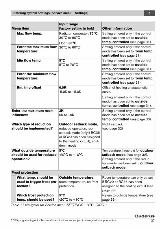
Entering system settings (Service menu – Settings) 6
Max flow temp. Radiator, convector: 75°C 30°C to 90°C
Floor: 50°C30°C to 60°C
Setting entered only if the control mode has been set to outside temp. controlled (see page 31).
Enter the maximum flow temperature:
Setting entered only if the control mode has been set to room temp. controlled (see page 31).
Min flow temp. 5°C 5°C to 70°C
Setting entered only if the control mode has been set to outside temp. controlled (see page 31).
Enter the minimum flow temperature:
Setting entered only if the control mode has been set to room temp. controlled (see page 31).
Rm. tmp offset 0.0K -5.0K to +5.0K
Offset of heating characteristic curve.
Setting entered only if the control mode has been set to outside temp. controlled (see page 31).
Enter the maximum room influence:
3K0K to 10K
Setting entered only if the control mode has been set to outside temp. controlled (see page 30).
Which type of reduction should be implemented?
Outdoor setback mode, reduced operation, room setback mode (only if RC35 or RC20 has been assigned to the heating circuit), shut-down mode
Night setback (see page 32)
What outside temperature should be used for reduced operation?
5°C-20°C to +10°C
Temperature threshold for outdoor setback mode (see page 32). Setting entered only if the reduc-tion mode has been set to outdoor setback mode.
Frost protectionWhat temp. should be used to trigger frost pro-tection?
Outside temperature, room temperature, no frost protection
Room temperature can only be set if RC20 or RC35 has been assigned to the heating circuit (see page 33).
Which frost protection temp. should be used?
5°C -20°C to +10°C
Refers to outside temperature (see page 33).
Menu itemInput range Factory setting in bold Other information
Table 11 Navigator for Service menu SETTINGS \ HTG. CIRC. 1
RC35 programming unit - Technical specifications are subject to change without prior notice. 27

Entering system settings (Service menu – Settings)6
At what outside temp. should reduction be interrupted?
OFF OFF, -30°C to +10°C
Setback in accordance with EN 12831 standard (see page 34).
Should domestic hot water priority be activated?
Yes, No
Mixer1)Is a mixer installed? Yes, No Can only be set for heating circuits
2 and up.1)
What running time does the mixer have?
120 seconds10 to 600 seconds
1)
What increase should be used for the boiler?
5K0 to 40K
1)
Drying floor screed1)Should a drying cycle be carried out?
Yes No Can only be set if floor heating has been entered as the heating sys-tem. DHW heating is not enabled while screed is drying.1)
Every how many days should the flow temp. be raised?
Every day, every 2nd day to every 5th day
1)
By how many degrees Kelvin should the flow temp. be raised each time?
5K0 to 10K
1)
What is the desired max-imum flow temperature?
45°C 25°C to 60°C
1)
For how many days should maximum flow temp. be maintained?
4 days0 to 20 days
1)
Every how many days should the flow temp. be reduced?
Direct normal operation, every day, every 2nd day to every 5th day
1)
Menu itemInput range Factory setting in bold Other information
Table 11 Navigator for Service menu SETTINGS \ HTG. CIRC. 1
RC35 programming unit - Technical specifications are subject to change without prior notice.28
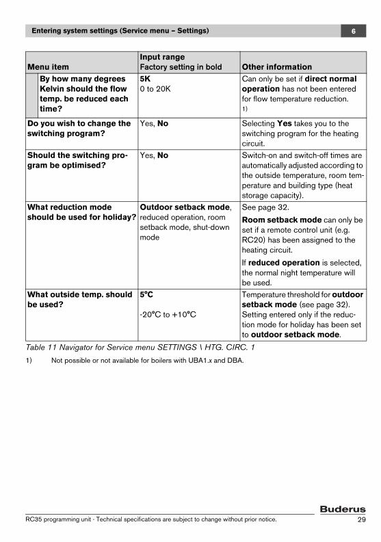
Entering system settings (Service menu – Settings) 6
By how many degrees Kelvin should the flow temp. be reduced each time?
5K0 to 20K
Can only be set if direct normal operation has not been entered for flow temperature reduction.1)
Do you wish to change the switching program?
Yes, No Selecting Yes takes you to the switching program for the heating circuit.
Should the switching pro-gram be optimised?
Yes, No Switch-on and switch-off times are automatically adjusted according to the outside temperature, room tem-perature and building type (heat storage capacity).
What reduction mode should be used for holiday?
Outdoor setback mode, reduced operation, room setback mode, shut-down mode
See page 32.
Room setback mode can only be set if a remote control unit (e.g. RC20) has been assigned to the heating circuit.
If reduced operation is selected, the normal night temperature will be used.
What outside temp. should be used?
5°C
-20°C to +10°C
Temperature threshold for outdoor setback mode (see page 32). Setting entered only if the reduc-tion mode for holiday has been set to outdoor setback mode.
1) Not possible or not available for boilers with UBA1.x and DBA.
Menu itemInput range Factory setting in bold Other information
Table 11 Navigator for Service menu SETTINGS \ HTG. CIRC. 1
RC35 programming unit - Technical specifications are subject to change without prior notice. 29

Entering system settings (Service menu – Settings)6
6.3.1 Assignment of programming unit / remote control unit in the software1
Example: Heating system with heating circuit 1 and heating circuit 2 (page 10)
6.3.2 Control mode (outside temp. controlled / room influence)
The temperature of the heating water in the boiler is defined by the heating characteristics determined in the Logamatic controller. A selection can be made whether these heating characteristics will be influenced solely by the outside temperature, or by a mixture of out-side temperature and room temperature.
– Outside temp. controlled: If this setting is entered, the boiler temperature calculated in the controller will be regulated by variation in the "delayed" response to outside tem-perature in combination with selected settings for target room temperature, offset, standard temperature and minimum outside temperature. This temperature is then delivered to the radiators or underfloor heating by means of permanent operation of the heating circuit pump. The only situations in which this setting could result in shut-down of the heating circuit pump are summer operation, night setback (depending on the reduction mode selected) or DHW mode (only with domestic hot water priority).
– Outside temp. controlled, influenced by room temperature (factory setting): this form of control works in exactly the same way as pure outside temperature control, except that you can use the maximum room influence parameter to determine whether and to what extent the room temperature should influence the heating charac-teristics. The programming unit / remote control unit must be installed in a reference room, so that a representative room temperature can be recorded.The greater the parameter set, the greater the influence of the room temperature on the heating characteristics (factory setting: 3 Kelvin). This applies when the room temper-
1) This function is not available with boilers with UBA1.x and DBA.
VariantSetting: Which operating unit is assigned to the heating circuit? Effect
A HC 1 = RC35, HC 2 = RC35(see Fig. 2, 1 on page 10)
Same room temperatures for HC 1 and HC 2
B HC 1 = RC35, HC 2 = none(see Fig. 2, 1 on page 10)
Room temperatures for HC 1 and HC 2 can be set separately
C HC 1 = RC20, HC 2 = RC35(see Fig. 2, 2 on page 10)
Room temperatures for HC 1 and HC 2 can be set separately; room temperatures for HC 1 are set on RC20
Table 12 Settings for room temperature depending on programming unit
RC35 programming unit - Technical specifications are subject to change without prior notice.30

Entering system settings (Service menu – Settings) 6
ature exceeds or falls below the target room temperature. If the maximum room influ-ence parameter is set to 0, the heating characteristics will be controlled solely by outside temperature.
6.3.3 Heating characteristics
Parameters: Standard temperature, maximum and minimum flow temperature and room temperature offset (parallel shifting of heating characteristic curve)
The heating characteristics form the basis of economical and easy operation of the heat-ing system with outside temperature control. To calculate the heating characteristics, the Logamatic control system requires the entry of a number of parameters for the heating sys-tem, from which the optimum heating characteristics are automatically calculated by a mathematical formula.
This calculation takes into account the "delayed" response to outside temperature and the room control temperature. The room control temperature is internally calculated, based on the desired room temperature (target room temperature) and the room influence factor.
This allows the user to influence the heating characteristics directly by modifying the tar-get room temperature.
The heating characteristic curve (Fig. 6, page 32) is determined by the base point and end point. The base point is located at 20°C flow temperature at a room temperature of 20°C with a delayed response to outside temperature of 20°C. The end point of the heating characteristic curve must be set according to the standard temperature (i.e. the design temperature) of the heating system.
The gradient of the heating characteristic curve (the shape of the curve) is determined by the parameters minimum outside temperature (the lowest outside temperature expected in a particular region; page 24) and the standard temperature (the flow tem-perature which should be reached when the outside temperature is at minimum) (Fig. 6, left).
The minimum flow temperature parameter can be used to define a minimum target value (Fig. 6, 4). If the temperature falls below this value, the burner is switched back on.
The heating characteristic curve can be shifted, up or down, in parallel to the original curve, by adjusting the room temperature offset parameter and/or the set room tem-
The x-axis of the heating characteristic curve shown on the display covers the range from +20°C to -20°C.For the std. tmp. parameter, the minimum outside temperature set in the "plant data" is indicated by a circle. However, the diagram will not be quite correct if a minimum outside temperature below -20°C is entered (the circle will no long-er be on the heating characteristic curve).
RC35 programming unit - Technical specifications are subject to change without prior notice. 31
Entering system settings (Service menu – Settings)6
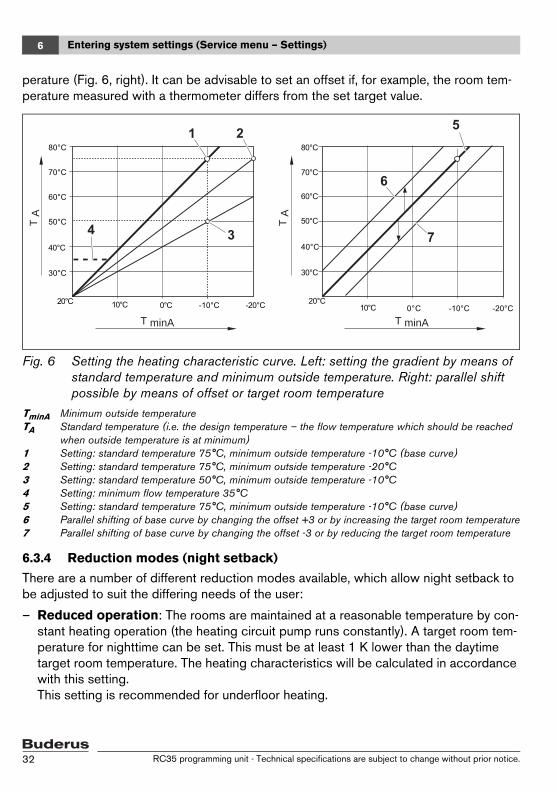
perature (Fig. 6, right). It can be advisable to set an offset if, for example, the room tem-perature measured with a thermometer differs from the set target value.
Fig. 6 Setting the heating characteristic curve. Left: setting the gradient by means of standard temperature and minimum outside temperature. Right: parallel shift possible by means of offset or target room temperature
TminA Minimum outside temperatureTA Standard temperature (i.e. the design temperature – the flow temperature which should be reached
when outside temperature is at minimum)1 Setting: standard temperature 75°C, minimum outside temperature -10°C (base curve)2 Setting: standard temperature 75°C, minimum outside temperature -20°C3 Setting: standard temperature 50°C, minimum outside temperature -10°C4 Setting: minimum flow temperature 35°C5 Setting: standard temperature 75°C, minimum outside temperature -10°C (base curve)6 Parallel shifting of base curve by changing the offset +3 or by increasing the target room temperature7 Parallel shifting of base curve by changing the offset -3 or by reducing the target room temperature
6.3.4 Reduction modes (night setback)
There are a number of different reduction modes available, which allow night setback to be adjusted to suit the differing needs of the user:
– Reduced operation: The rooms are maintained at a reasonable temperature by con-stant heating operation (the heating circuit pump runs constantly). A target room tem-perature for nighttime can be set. This must be at least 1 K lower than the daytime target room temperature. The heating characteristics will be calculated in accordance with this setting.This setting is recommended for underfloor heating.
7
T minA
T A
T A
T minA
RC35 programming unit - Technical specifications are subject to change without prior notice.32
Entering system settings (Service menu – Settings) 6
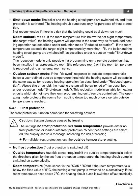
– Shut-down mode: The boiler and the heating circuit pump are switched off, and frost protection is activated. The heating circuit pump runs only for purposes of frost protec-tion. Not recommended if there is a risk that the building could cool down too much.
– Room setback mode: If the room temperature falls below the set night temperature (the target value), the heating system will operate in the same way as for reduced heat-ing operation (as described under reduction mode "Reduced operation"). If the room temperature exceeds the target night temperature by more than 1°K, the boiler and the heating circuit pump are switched off (as described under reduction mode "Shut-down mode"). This reduction mode is only possible if a programming unit / remote control unit has been installed in a representative room (the reference room) or if the room temperature is recorded using an external room sensor.
– Outdoor setback mode: If the "delayed" response to outside temperature falls below a user-defined outside temperature threshold, the heating system will operate in the same way as for reduced heating operation (as described under "Reduced opera-tion"). Above this threshold, the heating system will be switched off (as described under reduction mode "Shut-down mode"). This reduction mode is suitable for heating circuits which do not have their own programming unit / remote control unit. The oper-ating mode protects the rooms from cooling down too much once a certain outside temperature is reached.
6.3.5 Frost protectionThe frost protection function comprises the following options:
– No frost protection (frost protection is switched off)
– Outside temperature (outside sensor required) If the outside temperature falls below the threshold given by the set frost protection temperature, the heating circuit pump is switched on automatically.
– Room temperature (room sensor in the RC35 / RC20) If the room temperature falls below the fixed value of 5°C, the heating circuit pump is switched on automatically. If the room temperature rises above 7°C, the heating circuit pump is switched off automatically.
Caution: System damage caused by freezing
The settings no frost protection and room temperature provide either no frost protection or inadequate frost protection. When these settings are select-ed, the display shows a message indicating the risk of freezing.
For reliable frost protection, use the outside temperature setting.
RC35 programming unit - Technical specifications are subject to change without prior notice. 33
Entering system settings (Service menu – Settings)6
At what outside temp. should reduction be interrupted?
To maintain a comfortable level of warmth, the EN 12831 standard requires that heating surfaces and heat generators be designed to ensure a given level of output when the heat-ing system cools down below a given point as a result of night setback.
In the parameter At what outside temp. should reduction be interrupted?, you can set an outside temperature threshold (this threshold applies to the delayed" response to outside temperature; page 23).
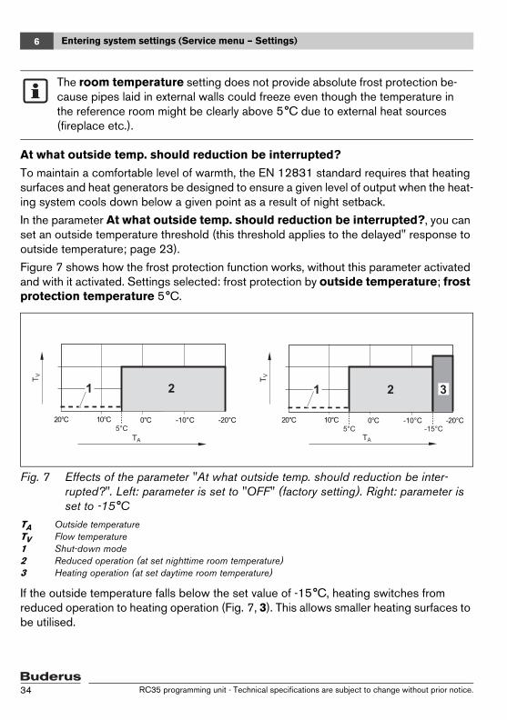
Figure 7 shows how the frost protection function works, without this parameter activated and with it activated. Settings selected: frost protection by outside temperature; frost protection temperature 5°C.
Fig. 7 Effects of the parameter "At what outside temp. should reduction be inter-rupted?". Left: parameter is set to "OFF" (factory setting). Right: parameter is set to -15°C
TA Outside temperatureTV Flow temperature1 Shut-down mode2 Reduced operation (at set nighttime room temperature)3 Heating operation (at set daytime room temperature)
If the outside temperature falls below the set value of -15°C, heating switches from reduced operation to heating operation (Fig. 7, 3). This allows smaller heating surfaces to be utilised.
The room temperature setting does not provide absolute frost protection be-cause pipes laid in external walls could freeze even though the temperature in the reference room might be clearly above 5°C due to external heat sources (fireplace etc.).
TATA
TV
5°C
TV
5°C -15°C
1 321 2
RC35 programming unit - Technical specifications are subject to change without prior notice.34

Entering system settings (Service menu – Settings) 6
6.4 Domestic hot water (DHW)
Warning: Risk of scalding at the taps
There is a risk of scalding at the taps whenever domestic hot water tempera-tures can be set to more than 60°C, and also during thermal disinfection.
Make your customers aware of this so that they do not open any taps for hot water without mixing in cold water as well.
Turn the rotary selector anti-clockwise until domestic hot
water is selected (marked with B).
Press to select domestic hot water.The menu SETTINGS \ DHW is opened.
Menu itemInput range Factory setting in bold Other information
Have you installed domes-tic hot water?
Yes, No Domestic hot water cannot be de-installed in the case of boilers with DBA.
Limiting value for maximum dom. hot water temp. set-ting:
60°C
60°C to 80°C
To which temperature should your domestic hot water be heated?
60°C
30°C to 80°C
If the limit is set to >60°C, it will be possible to set temperatures of that level in the User menu as well.
Which heating circuit should be used for domes-tic hot water?
3-way switching valve
Cylinder charge pump
1)
Do you wish to change the dom. hot water switching program?
Yes, No Selecting Yes takes you to the switching program for domestic hot water.
Circulation1)
Is circulation pump installed?
Yes, No 1)
Table 13 Navigator for Service menu SETTINGS \ DHW
SERVICE\SETTINGS
B
plant databoiler datadomestic hot waterheating circuit 1
RC35 programming unit - Technical specifications are subject to change without prior notice. 35

Entering system settings (Service menu – Settings)6
How frequently should the circul. pump be switched on per hour?
Once for 3 minutes, twice for 3 minutes, 3 times for 3 minutes, 4 times for 3 minutes, 5 times for 3 minutes, 6 times for 3 minutes, permanent operation
1)
Switch on circ. pump Graphical display of number of times the pump is switched on per hour.1)
Do you wish to change the circulation switch-ing program?
Yes, No Selecting Yes takes you to the switching program for hot water circulation.1)
Thermal disinfection1)
Should a thermal disin-fection be carried out?
Yes, No 1)
What temperature should be used for ther-mal disinfection?1)
70°C
60°C to 80°C
At temperatures above 60°C there is a risk of scalding at the taps dur-ing and after thermal disinfection. 1)
On which day should the thermal disinfection be performed?1)
Monday, Tuesday, Wednesday, Thursday, Fri-day, Saturday, Sunday, daily
1)
At what time of day should the th. disinfec-tion be performed?1)
1:00h0:00 to 23:00h
Times entered must be whole hours only (no minutes).1)
Should the LED of the sin-gle charge key be acti-vated?
Yes, No The single charge function (for one-off heating of hot water) still works but is no longer indicated by an LED.1)
1) Not possible or not available for boilers with UBA1.x and DBA.
Menu itemInput range Factory setting in bold Other information
Table 13 Navigator for Service menu SETTINGS \ DHW
RC35 programming unit - Technical specifications are subject to change without prior notice.36
Entering system settings (Service menu – Settings) 6
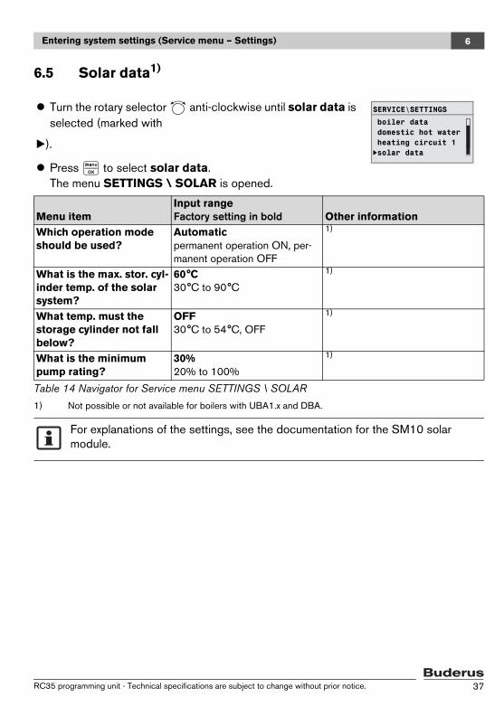
6.5 Solar data1)
Turn the rotary selector anti-clockwise until solar data is selected (marked with
B).
Press to select solar data.The menu SETTINGS \ SOLAR is opened.
Menu itemInput range Factory setting in bold Other information
Which operation mode should be used?
Automatic permanent operation ON, per-manent operation OFF
1)
1) Not possible or not available for boilers with UBA1.x and DBA.
What is the max. stor. cyl-inder temp. of the solar system?
60°C 30°C to 90°C
1)
What temp. must the storage cylinder not fall below?
OFF 30°C to 54°C, OFF
1)
What is the minimum pump rating?
30% 20% to 100%
1)
Table 14 Navigator for Service menu SETTINGS \ SOLAR
For explanations of the settings, see the documentation for the SM10 solar module.
boiler datadomestic hot waterheating circuit 1solar data
SERVICE\SETTINGS
B
RC35 programming unit - Technical specifications are subject to change without prior notice. 37
Entering system settings (Service menu – Settings)6
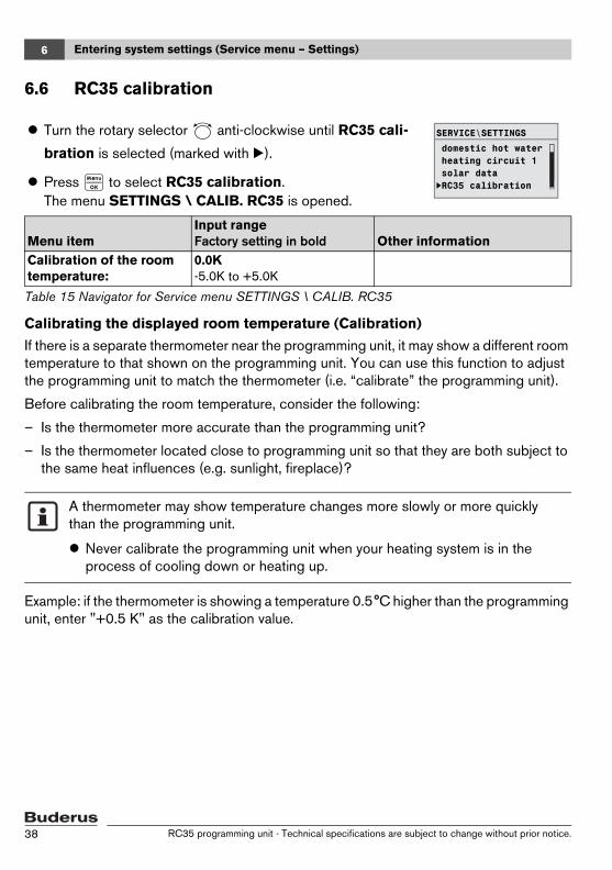
6.6 RC35 calibration
Calibrating the displayed room temperature (Calibration)
If there is a separate thermometer near the programming unit, it may show a different room temperature to that shown on the programming unit. You can use this function to adjust the programming unit to match the thermometer (i.e. “calibrate” the programming unit).
Before calibrating the room temperature, consider the following:
– Is the thermometer more accurate than the programming unit?
– Is the thermometer located close to programming unit so that they are both subject to the same heat influences (e.g. sunlight, fireplace)?
Example: if the thermometer is showing a temperature 0.5°C higher than the programming unit, enter "+0.5 K" as the calibration value.
Turn the rotary selector anti-clockwise until RC35 cali-
bration is selected (marked with B).
Press to select RC35 calibration.The menu SETTINGS \ CALIB. RC35 is opened.
Menu itemInput range Factory setting in bold Other information
Calibration of the room temperature:
0.0K -5.0K to +5.0K
Table 15 Navigator for Service menu SETTINGS \ CALIB. RC35
A thermometer may show temperature changes more slowly or more quickly than the programming unit.
Never calibrate the programming unit when your heating system is in the process of cooling down or heating up.
domestic hot waterheating circuit 1solar dataRC35 calibration
SERVICE\SETTINGS
B
RC35 programming unit - Technical specifications are subject to change without prior notice.38
Entering system settings (Service menu – Settings) 6
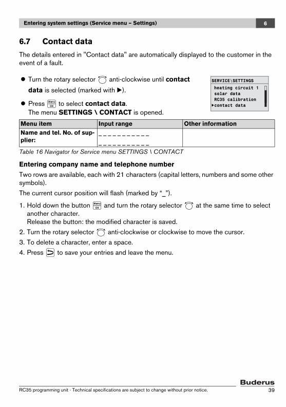
6.7 Contact data
The details entered in "Contact data" are automatically displayed to the customer in the event of a fault.
Entering company name and telephone number
Two rows are available, each with 21 characters (capital letters, numbers and some other symbols).
The current cursor position will flash (marked by “_”).
1. Hold down the button and turn the rotary selector at the same time to select another character.Release the button: the modified character is saved.
2. Turn the rotary selector anti-clockwise or clockwise to move the cursor.
3. To delete a character, enter a space.
4. Press to save your entries and leave the menu.
Turn the rotary selector anti-clockwise until contact
data is selected (marked with B).
Press to select contact data.The menu SETTINGS \ CONTACT is opened.
Menu item Input range Other informationName and tel. No. of sup-plier:
_ _ _ _ _ _ _ _ _ _ _
_ _ _ _ _ _ _ _ _ _ _
Table 16 Navigator for Service menu SETTINGS \ CONTACT
heating circuit 1
SERVICE\SETTINGS
B
solar dataRC35 calibrationcontact data
RC35 programming unit - Technical specifications are subject to change without prior notice. 39
Diagnosis7
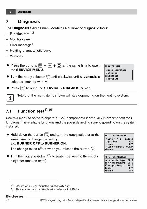
7 DiagnosisThe Diagnosis Service menu contains a number of diagnostic tools:
– Function test1, 2
– Monitor value
– Error message1
– Heating characteristic curve
– Versions
7.1 Function test1), 2)
Use this menu to activate separate EMS components individually in order to test their functions. The available functions and the possible settings vary depending on the system installed.
1) Boilers with DBA: restricted functionality only.2) This function is not available with boilers with UBA1.x.
Press the buttons + + at the same time to open the SERVICE MENU.
Turn the rotary selector anti-clockwise until diagnosis is selected (marked with ).
Press to open the SERVICE \ DIAGNOSIS menu.
Note that the menu items shown will vary depending on the heating system.
Hold down the button and turn the rotary selector at the same time to change the setting: e.g. BURNER OFF to BURNER ON.
The change takes effect when you release the button .
Turn the rotary selector to switch between different dis-plays (for function tests).
SERVICE MENU
quick operationsettingsdiagnosisservicing
B
valve 1 + 2 closedFCT. TEST\BOILER
ignition OFF flame OFF flame current 0.0µABburner ON
act. boil. tmp. 60°CFCT. TEST\BOILER
air temperature 32°Cflue gas temp. 78°Cflame OFFBburner OFF
RC35 programming unit - Technical specifications are subject to change without prior notice.40
Diagnosis 7
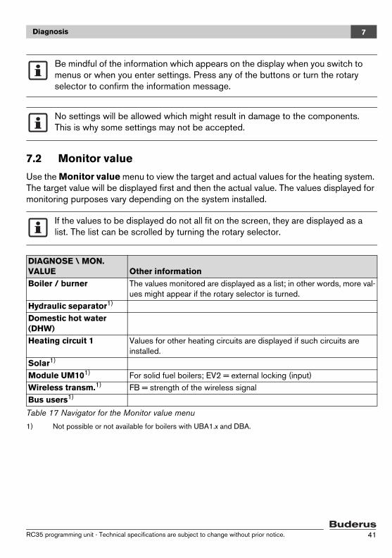
7.2 Monitor value
Use the Monitor value menu to view the target and actual values for the heating system. The target value will be displayed first and then the actual value. The values displayed for monitoring purposes vary depending on the system installed.
Be mindful of the information which appears on the display when you switch to menus or when you enter settings. Press any of the buttons or turn the rotary selector to confirm the information message.
No settings will be allowed which might result in damage to the components. This is why some settings may not be accepted.
If the values to be displayed do not all fit on the screen, they are displayed as a list. The list can be scrolled by turning the rotary selector.
DIAGNOSE \ MON. VALUE Other informationBoiler / burner The values monitored are displayed as a list; in other words, more val-
ues might appear if the rotary selector is turned.Hydraulic separator1)
1) Not possible or not available for boilers with UBA1.x and DBA.
Domestic hot water (DHW)Heating circuit 1 Values for other heating circuits are displayed if such circuits are
installed.Solar1)
Module UM101) For solid fuel boilers; EV2 = external locking (input)Wireless transm.1) FB = strength of the wireless signalBus users1)
Table 17 Navigator for the Monitor value menu
RC35 programming unit - Technical specifications are subject to change without prior notice. 41
Diagnosis7
7.3 Error message
Use the Error message menu to view the most recent faults in the fault memory, in order to investigate a fault, for example.
The faults are divided into the following categories:
– Current errors are all unresolved faults currently present in the system. These can be one of the following types: locking, blocking or plant error.
– Locking type error1: When the fault is remedied, the heating system needs to be unlocked manually. To do so, press the Reset button on the boiler.
– Blocking type error1: With blocking faults, the heating system resumes operation automatically as soon as the fault has been rectified.
– Plant errors in the heating system are logged in the RC35, with the exception of faults in the boiler or the burner, which are either "locking type errors" or "blocking type errors". The heating system keeps operating as much as possible during the fault; a reset is not required.
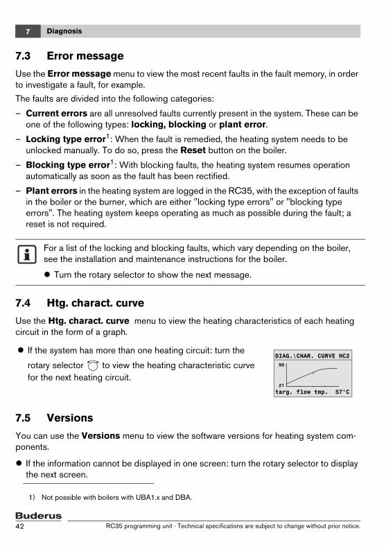
7.4 Htg. charact. curve
Use the Htg. charact. curve menu to view the heating characteristics of each heating circuit in the form of a graph.
7.5 Versions
You can use the Versions menu to view the software versions for heating system com-ponents.
If the information cannot be displayed in one screen: turn the rotary selector to display the next screen.
1) Not possible with boilers with UBA1.x and DBA.
For a list of the locking and blocking faults, which vary depending on the boiler, see the installation and maintenance instructions for the boiler.
Turn the rotary selector to show the next message.
If the system has more than one heating circuit: turn the
rotary selector to view the heating characteristic curve for the next heating circuit.
90DIAG.\CHAR. CURVE HC2
21targ. flow tmp. 57°C
RC35 programming unit - Technical specifications are subject to change without prior notice.42

Servicing 8
8 Servicing1
The Servicing menu is used to set a service interval and to view and reset current service messages.
The interval can be set to expire either after a given number of operating hours or when a given date is reached. The RC35 programming unit will then show a service message so that the customer can notify you to arrange an appointment.
Service messages are indicated by an Hxx code, e.g. H07.
1) Not possible with boilers with UBA1.x and DBA.
SERVICE MENU \ SERVICE Menu item
Input range Factory setting in bold Other information
Service interval How should servic-ing messages be triggered?
No messages, by date, by operation hours
Selecting date or opera-tion hours takes you automatically to the corre-sponding setting.
For “by date”: Annual servicing, starting on:
2000-01-01 To set the date:hold down and turn the rotary selector at the same time.
For “by operation hours”: Boiler oper-ation hours until next servicing mes-sage
1,000 h
1,000 h to 6,000 h
Number of hours of opera-tion with burner switched on
Current messages Message + code To view further messages: turn the rotary selector.
RESET servicing Do you wish to reset the servicing messages?
No, Yes If you select Yes the serv-icing messages will be reset. Note the information dis-played.
Table 18 Navigator for the Servicing menu
RC35 programming unit - Technical specifications are subject to change without prior notice. 43

RESET9
9 RESETThe SERVICE MENU \ RESET resets the following:
– All parameters back to their factory settings1
– The error list1,
– The service message2
– The operating hours2.
Turn the rotary selector to select a menu, e.g. error list.
Press to go to the relevant screen, e.g. Do you wish to reset the error list?
Press and turn the rotary selector to set the display to Yes.When the button is released, the reset is carried out. During this process, a corresponding message appears, which disappears again auto-matically.
Once reset is complete: confirm the new message by pressing any of the buttons.
1) In the case of boilers with UBA1.x and DBA, only all parameters of the RC35 will be reset, not the parameters of the boiler.
2) This function is not available with boilers with UBA1.x and DBA.
After resetting parameters to the factory setting, the parameters may need to be adjusted again to suit the system configuration.
RC35 programming unit - Technical specifications are subject to change without prior notice.44
Troubleshooting 10
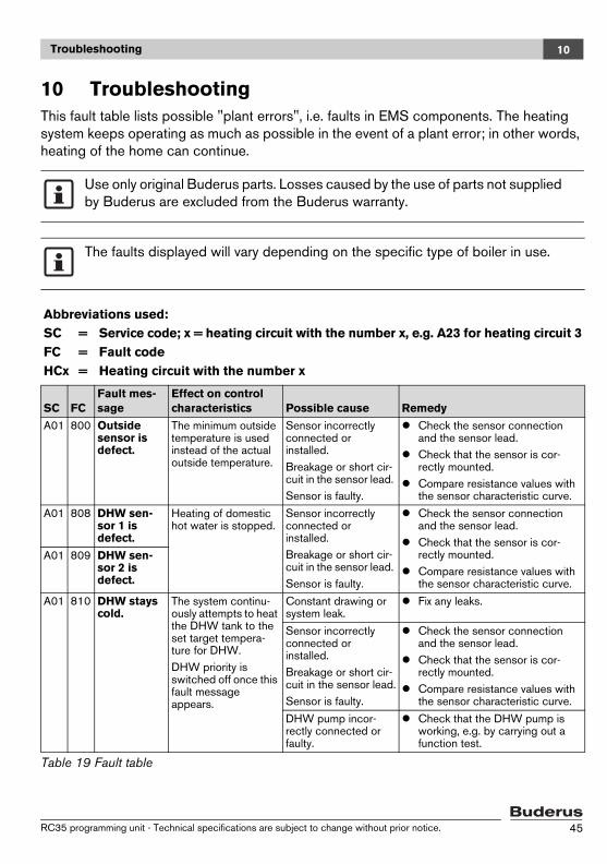
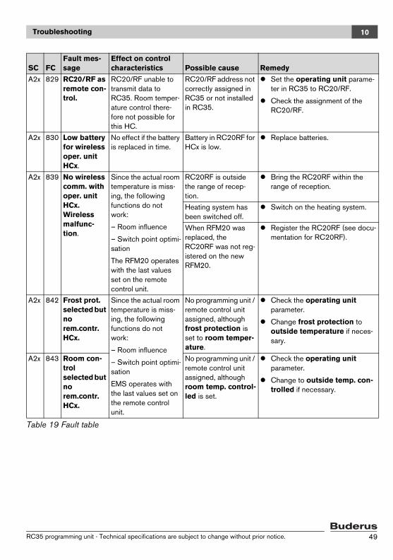
10 TroubleshootingThis fault table lists possible "plant errors", i.e. faults in EMS components. The heating system keeps operating as much as possible in the event of a plant error; in other words, heating of the home can continue.
Use only original Buderus parts. Losses caused by the use of parts not supplied by Buderus are excluded from the Buderus warranty.
The faults displayed will vary depending on the specific type of boiler in use.
Abbreviations used:SC = Service code; x = heating circuit with the number x, e.g. A23 for heating circuit 3FC = Fault codeHCx = Heating circuit with the number x
SC FCFault mes-sage
Effect on control characteristics Possible cause Remedy
A01 800 Outside sensor is defect.
The minimum outside temperature is used instead of the actual outside temperature.
Sensor incorrectly connected or installed.Breakage or short cir-cuit in the sensor lead. Sensor is faulty.
Check the sensor connection and the sensor lead.Check that the sensor is cor-rectly mounted.Compare resistance values with the sensor characteristic curve.
A01 808 DHW sen-sor 1 is defect.
Heating of domestic hot water is stopped.
Sensor incorrectly connected or installed.Breakage or short cir-cuit in the sensor lead. Sensor is faulty.
Check the sensor connection and the sensor lead.Check that the sensor is cor-rectly mounted.Compare resistance values with the sensor characteristic curve.
A01 809 DHW sen-sor 2 is defect.
A01 810 DHW stays cold.
The system continu-ously attempts to heat the DHW tank to the set target tempera-ture for DHW.DHW priority is switched off once this fault message appears.
Constant drawing or system leak.
Fix any leaks.
Sensor incorrectly connected or installed.Breakage or short cir-cuit in the sensor lead.Sensor is faulty.
Check the sensor connection and the sensor lead.Check that the sensor is cor-rectly mounted.Compare resistance values with the sensor characteristic curve.
DHW pump incor-rectly connected or faulty.
Check that the DHW pump is working, e.g. by carrying out a function test.
Table 19 Fault table
RC35 programming unit - Technical specifications are subject to change without prior notice. 45
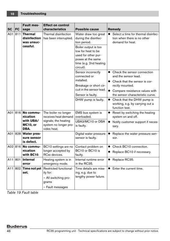
Troubleshooting10
A01 811 Thermal disinfection was unsuc-cessful.
Thermal disinfection has been interrupted.
Water draw too great during the disinfec-tion period.
Select a time for thermal disinfec-tion when there is no other demand for heat.
Boiler output is too low for heat to be used for other pur-poses at the same time (e.g. 2nd heating circuit).
Sensor incorrectly connected or installed.
Breakage or short cir-cuit in the sensor lead.
Sensor is faulty.
Check the sensor connection and the sensor lead.
Check that the sensor is cor-rectly mounted.
Compare resistance values with the sensor characteristic curve.
DHW pump is faulty. Check that the DHW pump is working, e.g. by carrying out a function test.
A01 816 No commu-nication with UBA/MC10, or DBA.
The boiler no longer receives heat demand signals; the heating system no longer pro-vides heat.
EMS bus system is overloaded.
Reset by switching the heating system on and off.
Notify customer support if neces-sary.
UBA3/MC10 or DBA is faulty.
A01 828 Water pres-sure sensor is defect.
Digital water pressure sensor is faulty.
Replace the water pressure sen-sor.
A02 816 No commu-nication with BC10.
BC10 settings are no longer accepted by RCxx devices.
Contact problem on BC10 or BC10 is faulty.
Check BC10 connection.
Replace BC10 if necessary.
A11 801 Internal error
Heating system is in emergency mode.
Internal runtime error in the RC35.
Replace RC35.
A11 802 Time not yet set.
Restricted functional-ity for:
– All switching pro-grams
– Fault messages
Time details are miss-ing, e.g. due to lengthy power failure.
Enter the current time.
SC FCFault mes-sage
Effect on control characteristics Possible cause Remedy
Table 19 Fault table
RC35 programming unit - Technical specifications are subject to change without prior notice.46
Troubleshooting 10
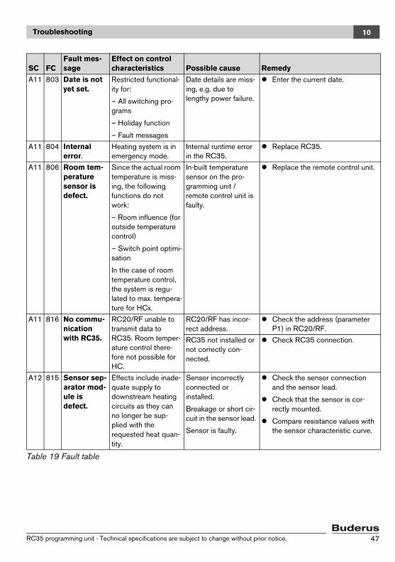
A11 803 Date is not yet set.
Restricted functional-ity for:
– All switching pro-grams
– Holiday function
– Fault messages
Date details are miss-ing, e.g. due to lengthy power failure.
Enter the current date.
A11 804 Internal error.
Heating system is in emergency mode.
Internal runtime error in the RC35.
Replace RC35.
A11 806 Room tem-perature sensor is defect.
Since the actual room temperature is miss-ing, the following functions do not work:
– Room influence (for outside temperature control)
– Switch point optimi-sation
In the case of room temperature control, the system is regu-lated to max. tempera-ture for HCx.
In-built temperature sensor on the pro-gramming unit / remote control unit is faulty.
Replace the remote control unit.
A11 816 No commu-nication with RC35.
RC20/RF unable to transmit data to RC35. Room temper-ature control there-fore not possible for HC.
RC20/RF has incor-rect address.
Check the address (parameter P1) in RC20/RF.
RC35 not installed or not correctly con-nected.
Check RC35 connection.
A12 815 Sensor sep-arator mod-ule is defect.
Effects include inade-quate supply to downstream heating circuits as they can no longer be sup-plied with the requested heat quan-tity.
Sensor incorrectly connected or installed.
Breakage or short cir-cuit in the sensor lead.
Sensor is faulty.
Check the sensor connection and the sensor lead.
Check that the sensor is cor-rectly mounted.
Compare resistance values with the sensor characteristic curve.
SC FCFault mes-sage
Effect on control characteristics Possible cause Remedy
Table 19 Fault table
RC35 programming unit - Technical specifications are subject to change without prior notice. 47
Troubleshooting10
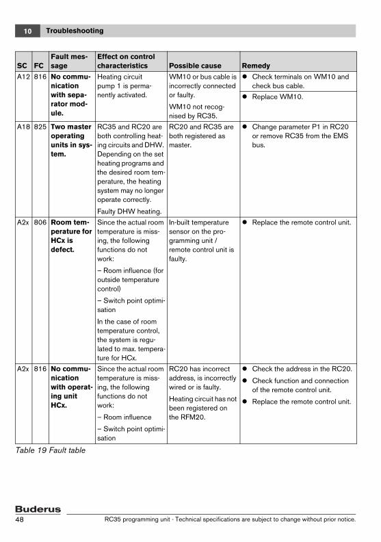
A12 816 No commu-nication with sepa-rator mod-ule.
Heating circuit pump 1 is perma-nently activated.
WM10 or bus cable is incorrectly connected or faulty.
WM10 not recog-nised by RC35.
Check terminals on WM10 and check bus cable.
Replace WM10.
A18 825 Two master operating units in sys-tem.
RC35 and RC20 are both controlling heat-ing circuits and DHW. Depending on the set heating programs and the desired room tem-perature, the heating system may no longer operate correctly.
Faulty DHW heating.
RC20 and RC35 are both registered as master.
Change parameter P1 in RC20 or remove RC35 from the EMS bus.
A2x 806 Room tem-perature for HCx is defect.
Since the actual room temperature is miss-ing, the following functions do not work:
– Room influence (for outside temperature control)
– Switch point optimi-sation
In the case of room temperature control, the system is regu-lated to max. tempera-ture for HCx.
In-built temperature sensor on the pro-gramming unit / remote control unit is faulty.
Replace the remote control unit.
A2x 816 No commu-nication with operat-ing unit HCx.
Since the actual room temperature is miss-ing, the following functions do not work:
– Room influence
– Switch point optimi-sation
RC20 has incorrect address, is incorrectly wired or is faulty.
Heating circuit has not been registered on the RFM20.
Check the address in the RC20.
Check function and connection of the remote control unit.
Replace the remote control unit.
SC FCFault mes-sage
Effect on control characteristics Possible cause Remedy
Table 19 Fault table
RC35 programming unit - Technical specifications are subject to change without prior notice.48
Troubleshooting 10
A2x 829 RC20/RF as remote con-trol.
RC20/RF unable to transmit data to RC35. Room temper-ature control there-fore not possible for this HC.
RC20/RF address not correctly assigned in RC35 or not installed in RC35.
Set the operating unit parame-ter in RC35 to RC20/RF.
Check the assignment of the RC20/RF.
A2x 830 Low battery for wireless oper. unit HCx.
No effect if the battery is replaced in time.
Battery in RC20RF for HCx is low.
Replace batteries.
A2x 839 No wireless comm. with oper. unit HCx.Wireless malfunc-tion.
Since the actual room temperature is miss-ing, the following functions do not work:
– Room influence
– Switch point optimi-sation
The RFM20 operates with the last values set on the remote control unit.
RC20RF is outside the range of recep-tion.
Bring the RC20RF within the range of reception.
Heating system has been switched off.
Switch on the heating system.
When RFM20 was replaced, the RC20RF was not reg-istered on the new RFM20.
Register the RC20RF (see docu-mentation for RC20RF).
A2x 842 Frost prot.selected but norem.contr. HCx.
Since the actual room temperature is miss-ing, the following functions do not work:
– Room influence
– Switch point optimi-sation
EMS operates with the last values set on the remote control unit.
No programming unit / remote control unit assigned, although frost protection is set to room temper-ature.
Check the operating unit parameter.
Change frost protection to outside temperature if neces-sary.
A2x 843 Room con-trol selected but no rem.contr. HCx.
No programming unit / remote control unit assigned, although room temp. control-led is set.
Check the operating unit parameter.
Change to outside temp. con-trolled if necessary.
SC FCFault mes-sage
Effect on control characteristics Possible cause Remedy
Table 19 Fault table
RC35 programming unit - Technical specifications are subject to change without prior notice. 49
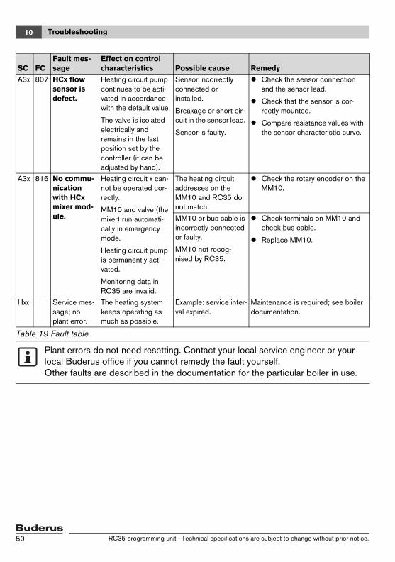
Troubleshooting10
A3x 807 HCx flow sensor is defect.
Heating circuit pump continues to be acti-vated in accordance with the default value.
The valve is isolated electrically and remains in the last position set by the controller (it can be adjusted by hand).
Sensor incorrectly connected or installed.
Breakage or short cir-cuit in the sensor lead.
Sensor is faulty.
Check the sensor connection and the sensor lead.
Check that the sensor is cor-rectly mounted.
Compare resistance values with the sensor characteristic curve.
A3x 816 No commu-nication with HCx mixer mod-ule.
Heating circuit x can-not be operated cor-rectly.
MM10 and valve (the mixer) run automati-cally in emergency mode.
Heating circuit pump is permanently acti-vated.
Monitoring data in RC35 are invalid.
The heating circuit addresses on the MM10 and RC35 do not match.
Check the rotary encoder on the MM10.
MM10 or bus cable is incorrectly connected or faulty.
MM10 not recog-nised by RC35.
Check terminals on MM10 and check bus cable.
Replace MM10.
Hxx Service mes-sage; no plant error.
The heating system keeps operating as much as possible.
Example: service inter-val expired.
Maintenance is required; see boiler documentation.
Plant errors do not need resetting. Contact your local service engineer or your local Buderus office if you cannot remedy the fault yourself. Other faults are described in the documentation for the particular boiler in use.
SC FCFault mes-sage
Effect on control characteristics Possible cause Remedy
Table 19 Fault table
RC35 programming unit - Technical specifications are subject to change without prior notice.50
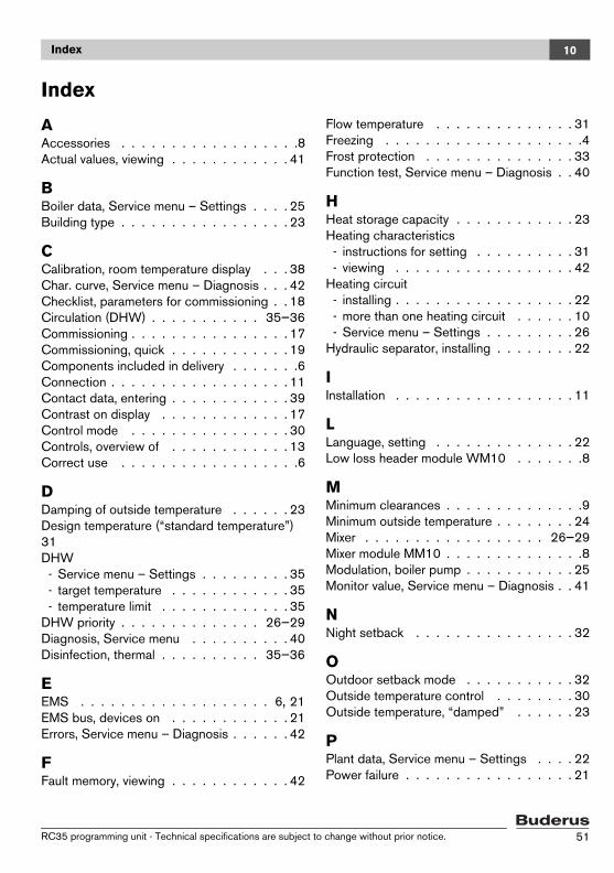
Index 10
Index
AAccessories . . . . . . . . . . . . . . . . . .8Actual values, viewing . . . . . . . . . . . . 41
BBoiler data, Service menu – Settings . . . . 25Building type . . . . . . . . . . . . . . . . . 23
CCalibration, room temperature display . . . 38Char. curve, Service menu – Diagnosis . . . 42Checklist, parameters for commissioning . . 18Circulation (DHW) . . . . . . . . . . . 35–36Commissioning . . . . . . . . . . . . . . . . 17Commissioning, quick . . . . . . . . . . . . 19Components included in delivery . . . . . . .6Connection . . . . . . . . . . . . . . . . . . 11Contact data, entering . . . . . . . . . . . . 39Contrast on display . . . . . . . . . . . . . 17Control mode . . . . . . . . . . . . . . . . 30Controls, overview of . . . . . . . . . . . . 13Correct use . . . . . . . . . . . . . . . . . .6
DDamping of outside temperature . . . . . . 23Design temperature (“standard temperature”) 31DHW - Service menu – Settings . . . . . . . . . 35 - target temperature . . . . . . . . . . . . 35 - temperature limit . . . . . . . . . . . . . 35DHW priority . . . . . . . . . . . . . . 26–29Diagnosis, Service menu . . . . . . . . . . 40Disinfection, thermal . . . . . . . . . . 35–36
EEMS . . . . . . . . . . . . . . . . . . . 6, 21EMS bus, devices on . . . . . . . . . . . . 21Errors, Service menu – Diagnosis . . . . . . 42
FFault memory, viewing . . . . . . . . . . . . 42
Flow temperature . . . . . . . . . . . . . . 31Freezing . . . . . . . . . . . . . . . . . . . .4Frost protection . . . . . . . . . . . . . . . 33Function test, Service menu – Diagnosis . . 40
HHeat storage capacity . . . . . . . . . . . . 23Heating characteristics - instructions for setting . . . . . . . . . . 31 - viewing . . . . . . . . . . . . . . . . . . 42Heating circuit - installing . . . . . . . . . . . . . . . . . . 22 - more than one heating circuit . . . . . . 10 - Service menu – Settings . . . . . . . . . 26Hydraulic separator, installing . . . . . . . . 22
IInstallation . . . . . . . . . . . . . . . . . . 11
LLanguage, setting . . . . . . . . . . . . . . 22Low loss header module WM10 . . . . . . .8
MMinimum clearances . . . . . . . . . . . . . .9Minimum outside temperature . . . . . . . . 24Mixer . . . . . . . . . . . . . . . . . . 26–29Mixer module MM10 . . . . . . . . . . . . . .8Modulation, boiler pump . . . . . . . . . . . 25Monitor value, Service menu – Diagnosis . . 41
NNight setback . . . . . . . . . . . . . . . . 32
OOutdoor setback mode . . . . . . . . . . . 32Outside temperature control . . . . . . . . 30Outside temperature, “damped” . . . . . . 23
PPlant data, Service menu – Settings . . . . 22Power failure . . . . . . . . . . . . . . . . . 21
RC35 programming unit - Technical specifications are subject to change without prior notice. 51

Index10
Programming unit - assignment in software . . . . . . . . . 30 - attaching or removing . . . . . . . . . . 12 - for heating circuit . . . . . . . . . . . . 26 - only programming unit in the system . . 10Pump after-run time . . . . . . . . . . . . . 25Pump anti-seize . . . . . . . . . . . . . . . 21
QQuick operation, Service menu . . . . . . . 19
RReduced operation . . . . . . . . . . . . . 32Reduction mode (night setback) . . . . . . 32Reference room . . . . . . . . . . . . . . . . 9Remote control unit . . . . . . . . . . . . . 10Reset, Service menu . . . . . . . . . . . . 44Room influence . . . . . . . . . . . . . . . 30Room setback mode . . . . . . . . . . . . 32Room temperature offset . . . . . . . . . . 31
SSafety instructions . . . . . . . . . . . . . . 4Screed, drying . . . . . . . . . . . . . . 26–29Sensor characteristics . . . . . . . . . . . . 7Service interval, setting . . . . . . . . . . . 43Service menu, introduction . . . . . . . . . 14Service menu, overview of the menus . . . 16Service messages, viewing/resetting . . . . 43Servicing, Service menu . . . . . . . . . . 43Setback, interrupting (frost protection) . . . 33Shut-down . . . . . . . . . . . . . . . . . . 21Shut-down mode . . . . . . . . . . . . . . 32Single charge LED, switching off . . . . 35–36Solar data, Service menu – Settings . . . . 37Solar module, installing . . . . . . . . . . . 22Specifications . . . . . . . . . . . . . . . . . 7Switching off . . . . . . . . . . . . . . . . 21Switching program, optimising . . . . . 26–29Symbols, explanation of . . . . . . . . . . . . 5System handover . . . . . . . . . . . . . . 20
TTarget values, viewing . . . . . . . . . . . . 41
Temperature sensor . . . . . . . . . . . . . . 7Testing components . . . . . . . . . . . . 40Thermal disinfection . . . . . . . . . . . 35–36Thermostatic valves in reference room . . . 21Troubleshooting . . . . . . . . . . . . . . . 45
VVersions, Service menu – Diagnosis . . . . 42Versions, viewing . . . . . . . . . . . . . . 42
WWeather-dependent control . . . . . . . . 30
RC35 programming unit - Technical specifications are subject to change without prior notice.52

Notice
RC35 programming unit - Technical specifications are subject to change without prior notice. 53

Notice
RC35 programming unit - Technical specifications are subject to change without prior notice.54

Notice
RC35 programming unit - Technical specifications are subject to change without prior notice. 55

BuderusCotswold Way, WarndonWorcester WR4 9SWTel.: 01905 752794Fax: 01905 753130www.buderus.co.uk