ins p i r e d e ffi cien y - mikrofillmikrofill.com/uploads/files/technical documentation /issue...
TRANSCRIPT

H I G H E F F I C I E N C Y
H O T W A T E R S Y S T E M S
I N S P I R E D E F F I C I E N C Y
EXTREME HIGH EFFICIENCY HOT WATER SYSTEMS wi th INJECTION DYNAMICSTECHNICAL DOCUMENTATION
ISSUE 03/16 Rev. 01


TABLE OF CONTENTS
TECHNICAL DOCUMENTATION 03
1.
2.
3.
4.
5.
6.
7.
Technical Data Electrical Details Connection Details Dimensions Standing Losses
Flow Characteristics Flow Characteristics Flow Characteristics continued
Overview Description
Operation Operation
Installation Siting Over Heat Protection Open Vented Applications Discharge Pipework Discharge Pipework continued Unvented Mains Kit Valve Multiple Rapide Extreme Installation Electrical Connections Electrical Data Sensor Schematic Two Port Valve Wiring
Operation Operating Status Maintenance Diagnostic Mode Fault Diagnosis
04
0506
07
08
09
10111213
1415
16
17

TECHNICAL DATA
04 TECHNICAL DOCUMENTATION
EXTREME 50050098
1½”1”2828
1½”120100230503
EXTREME 500910810570
126515101810735300
EXTREME 50050
36412.13.36
D
EXTREME 30030077
1¼”1”2828
1¼”120100230503
EXTREME 300910810465
126015301830710300
EXTREME 3001001976.6
1.83B
EXTREME 200200631”1”28281”
120100230503
EXTREME 200380280465735995
1305710300
EXTREME 2001001555.21.2B
litrekgBSPBSPmmmmBSPkWWVHzA
mm mm mm mm mm mm mm mm
mm MJ MJ kWh
GENERAL
Model Water Content of Appliance Weight (Empty) DHW Flow Connection DHW Return Connection Primary Flow Connection Primary Return Connection Mains Cold Water Supply Connection Maximum Plate Heat Exchanger Input Power Consumption (max) Electrical Supply Frequency Fuse Protection
DIMENSIONS
Model A B C D E F G H
Model Insulation Thickness Standing Losses per Month Standing Losses per Day Standing Losses per Day Energy Efficiency Class
EFFICIENCY
30
40
50
60
70
80
90
100
110
120
300 400 500 600 700 800 900 1000200
Rapide Extreme 200
Rapide Extreme 300
Rapide Extreme 500
Hea
t Inp
ut (k
W)
DHWS Flow (litres)
2200
30
40
50
60
70
80
90
100
110
120
500 550 600 650 700 750 800 850 900 950 1000 1050 1100 1150 1200 1250 1300 1350 1400 1450 1500 1550 1600 1650 1700 1750 1800 1850 1900 1950 2000 2050 2100 2150 2250 2300 2350 2400 2450 2500 2550 2600
Rapide Extreme 200
Rapide Extreme 300
Rapide Extreme 500
Hea
t Inp
ut (k
W)
DHWS Flow (litres)
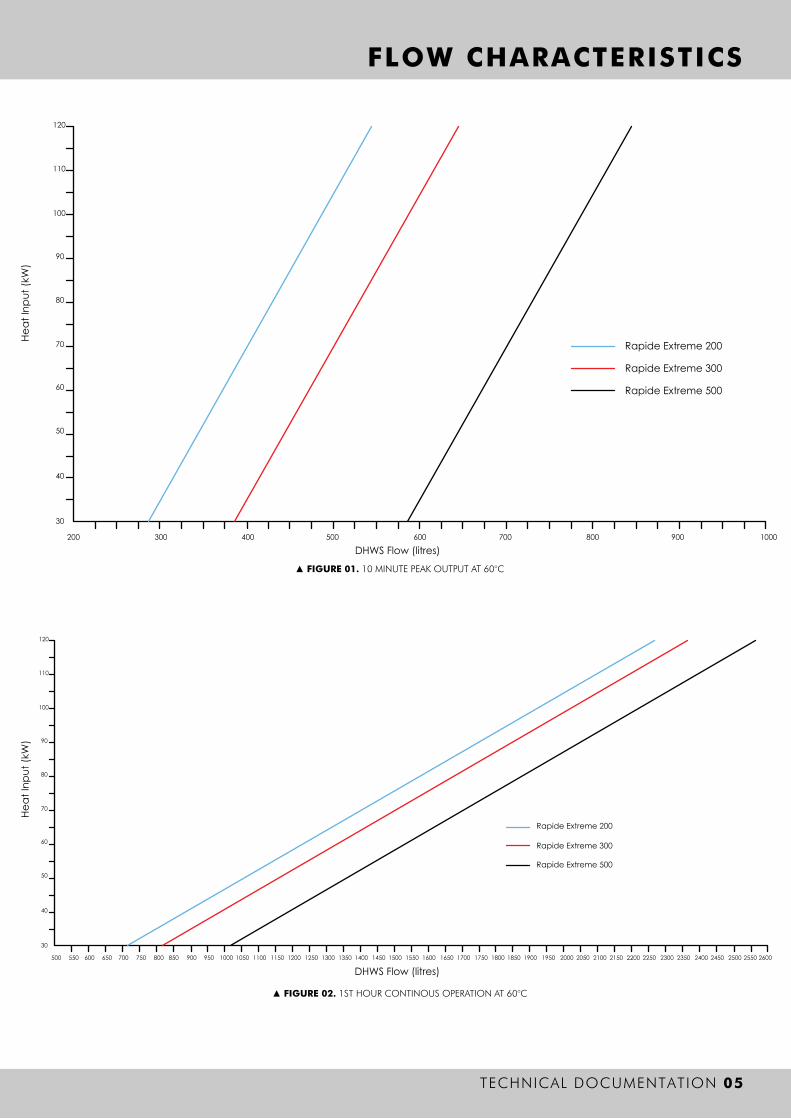
FLOW CHARACTERISTICS
TECHNICAL DOCUMENTATION 05
▲ FIGURE 01. 10 MINUTE PEAK OUTPUT AT 60°C
▲ FIGURE 02. 1ST HOUR CONTINOUS OPERATION AT 60°C

30
40
50
60
70
80
90
100
110
120
0 50 100 150 200 250 300 350 400 450 500 550 600 650 700 750 800 850 900 950 1000 1050 1100 1150 1200 1250 1300 1350 1400 1450 1500 1550 1600 1650 1700 1750 1800 1850 1900 1950 2000 2050 2100
Hea
t Inp
ut (k
W)
DHWS Flow (litres)
40 50 60 70 80 90 100 110 120
5
10
15
20
25
30
35
40
45
50
0.1
0.2
0.3
0.4
0.5
0.6
0.7
0.8
0.9
1.0
00
30
Flow RateResistance
FlowRate
l/s
ResistancekPa
kW Rating Input
FLOW CHARACTERISTICS
06 TECHNICAL DOCUMENTATION
▲ FIGURE 03. CONTINUOUS OPERATION AT 60°C
▲ FIGURE 04. PRIMARY FLOW CHARACTERISTICS

OVERVIEW
TECHNICAL DOCUMENTATION 07
DESCRIPTION
The Mikrofill Rapide Extreme is a domestic hot water generator that combines the advantages of both an instantaneous water heater and a storage system, whilst ensuring that the associated boiler plant operates at its optimum efficiency during domestic hot water generation. The Rapide Extreme is suitable for open vented or unvented applications. Based on a stainless steel storage vessel the unit utilises a stainless steel plate heat exchanger to “load” the vessel with water at a minimum of 60°C, during hot water demand the plate heat exchanger effectively delivers hot water directly to the outlets, so “heat up” is reduced to minutes and “recovery time” is a thing of the past. The Rapide Extreme does not rely on convection within the vessel to transfer heat, the loading system introduces water at 60°C in to the top of the vessel. This drastically reduces the proliferation of Legionella bacilli, and in instances where the associated boiler is of the condensing type, the boiler will remain in condensing mode throughout domestic hot water generation; a situation that is unattainable using conventional coil type hot water cylinders.The Rapide Extreme is supplied fully assembled, prewired and inclusive of loading pump and electronic controller, advanced insulation ensures standing losses are reduced to a minimum. The anode free stainless steel vessel carries a 30 year guarantee, whilst maintenance is minimal.
Advantages
Domestic hot water available at all times Very high flow rates available Generates full cylinder of water at 60°C Reduces legionella risk Optimises boiler operation Simple installation Low maintenance Low standing losses 30 year guarantee on cylinder Short payback period
OPERATION
08 TECHNICAL DOCUMENTATION
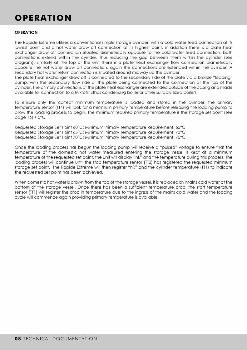
OPERATION
The Rapide Extreme utilises a conventional simple storage cylinder, with a cold water feed connection at its lowest point and a hot water draw off connection at its highest point, in addition there is a plate heat exchanger draw off connection situated diametrically opposite to the cold water feed connection, both connections extend within the cyinder, thus reducing the gap between them within the cylinder (see diagram). Similarly at the top of the unit there is a plate heat exchanger flow connection diametrically opposite the hot water draw off connection, again the connections are extended within the cylinder. A secondary hot water return connection is situated around midway up the cylinder. The plate heat exchanger draw off is connected to the secondary side of the plate via a bronze “loading” pump, with the secondary flow side of the plate being connected to the connection at the top of the cylinder. The primary connections of the plate heat exchanger are extended outside of the casing and made available for connection to a Mikrofill Ethos condensing boiler or other suitably sized boilers.
To ensure only the correct minimum temperature is loaded and stored in the cylinder, the primary temperature sensor (TT4) will look for a minimum primary temperature before releasing the loading pump to allow the loading process to begin. The minimum required primary temperature is the storage set point (see page 16) + 5°C.
Requested Storage Set Point 60°C: Minimum Primary Temperature Requirement: 65°CRequested Storage Set Point 65°C: Minimum Primary Temperature Requirement: 70°CRequested Storage Set Point 70°C: Minimum Primary Temperature Requirement: 75°C
Once the loading process has begun the loading pump will receive a “pulsed” voltage to ensure that the temperature of the domestic hot water measured entering the storage vessel is kept at a minimum temperature of the requested set point, the unit will display “nL” and the temperature during this process. The loading process will continue until the stop temperature sensor (TT2) has registered the requested minimum storage set point. The Rapide Extreme will then register “nR” and the cylinder temperature (TT1) to indicate the requested set point has been achieved.
When domestic hot water is drawn from the top of the storage vessel, it is replaced by mains cold water at the bottom of the storage vessel. Once there has been a sufficient temperature drop, the start temperature sensor (TT1) will register the drop in temperature due to the ingress of the mains cold water and the loading cycle will commence again providing primary temperature is available.

INSTALLATION
TECHNICAL DOCUMENTATION 09
INSTALLATION
IMPORTANT: Please read and understand these instructions before installing the Rapide Extreme hot water loading system. Incorrect installation may invalidate the guarantee.
The Rapide Extreme must be installed by a competent installer in accordance with Building Regulation G3 (England and Wales), Technical Standard P3 (Scotland) or Building Regulation P5 (Northern Ireland).
Siting the Rapide Extreme
The Rapide Extreme must be vertically floor mounted. It can be placed anywhere convenient provided the discharge pipe(s) from its safety valve can be correctly installed. Areas that are subject to freezing must be avoided. Ensure that the the floor is of sufficient strength to support the full weight of the unit. Pipe runs should be kept as short as possible for maximum economy. Access to associated controls and immersion heater (if installed) should be possible for servicing and maintenance of the system.
Over Heat Protection Device
The supplied two port spring return valve must be fitted to the primary flow or return pipework to the cylinder as part of the over heat protection for the cylinder to comply with G3 regulations. See wiring diagram for electrical connection information.
Protection Against Under Pressure
A suitable form of protection should be fitted to prevent damage occuring to the cylinder; in the event the cylinder is subjected to a vacuum.
Application
The Rapide Extreme is suitable for both open vented (storage tank fed) or unvented applications.
Open Vented Applications
This application utilises feed from a storage tank and where the system is open to atmosphere via a vent pipe (usually discharging back in to the storage tank). Available pressure is subject to the static head i.e. the height of the storage tank above the Rapide Extreme. In open vented applications it is recommended that the cold water feed pipework and the domestic hot water flow pipe are sized according to the Rapide Extreme tapping size to ensure maximum flow rates.
When installing the Rapide Extreme on to an open vented system we strongly recommend that a strainer / filter of 100 micron mesh is installed on the domestic hot water return pipework and cold water feed pipework, failure to do so may invalidate the guarantee.

▲ FIGURE 05. SCHEMATIC INSTALLATION DETAIL FOR UNVENTED APPLICATIONS
INSTALLATION
10 TECHNICAL DOCUMENTATION
INSTALLATION
The Rapide Extreme can be fed directly from the mains cold water supply to the property without the need for seperate feed cisterns or vent pipes. It is supplied complete with all its necessary inlet and safety controls, thermal cut out and two port motorised valve in the mains unvented kit.
Examples of acceptable discharge arrangements are:
• Ideally below a fixed grating and above the water seal in a trapped gully.
• Downward discharges at low level; i.e. up to 100mm above external surfaces such as car parks, hard standings, grassed areas etc are acceptable providing that where children may play or otherwise come in to contact with discharges a wire cage or similar guard is positioned to prevent contact, whilst mantaining visibility.
• Discharges at high level; e.g. in to a metal hopper and metal downpipe with the end of the discharge clearly visible (tundish visible or not) or on to a roof capable of withstanding high temperature discharges of water and 3m from any plastic guttering systems that would collect such discharges (tundish visible).
• Where a single pipe serves a number of discharges, such as in blocks of flats, the number served should be limited to no more than 6 systems so that any installation discharging can be traced reasonably easily. The single common discharge pipe should be at least one pipe size larger than the largest individual discharge pipe (D2) to be connected. If unvented hot water storage systems are installed where discharges from safety devices may not be apparent, i.e. dwellings occupied by blind, infirm or disabled people, consideration should be given to the installation of an electronically operated device to warn when discharge takes place.
Note: The discharge will consist of scalding water and steam. Asphalt, roofing and non-metallic rainwater goods may be damaged by such discharges.
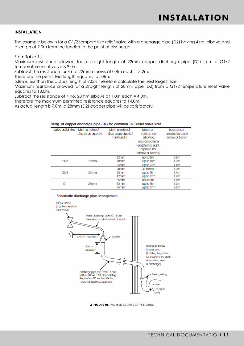
▲ FIGURE 06. WORKED EXAMPLE OF PIPE SIZING
INSTALLATION
TECHNICAL DOCUMENTATION 11
INSTALLATION
The example below is for a G1/2 temperature relief valve with a discharge pipe (D2) having 4 no. elbows and a length of 7.0m from the tundish to the point of discharge.
From Table 1: Maximum resistance allowed for a straight length of 22mm copper discharge pipe (D2) from a G1/2 temperature relief valve is 9.0m.Subtract the resistance for 4 no. 22mm elbows at 0.8m each = 3.2m.Therefore the permitted length equates to 5.8m.5.8m is less than the actual length of 7.0m therefore calculate the next largest size.Maximum resistance allowed for a straight length of 28mm pipe (D2) from a G1/2 temperature relief valve equates to 18.0m. Subtract the resistance of 4 no. 28mm elbows at 1.0m each = 4.0m.Therefore the maximum permitted resistance equates to 14.0m.As actual length is 7.0m, a 28mm (D2) copper pipe will be satisfactory.
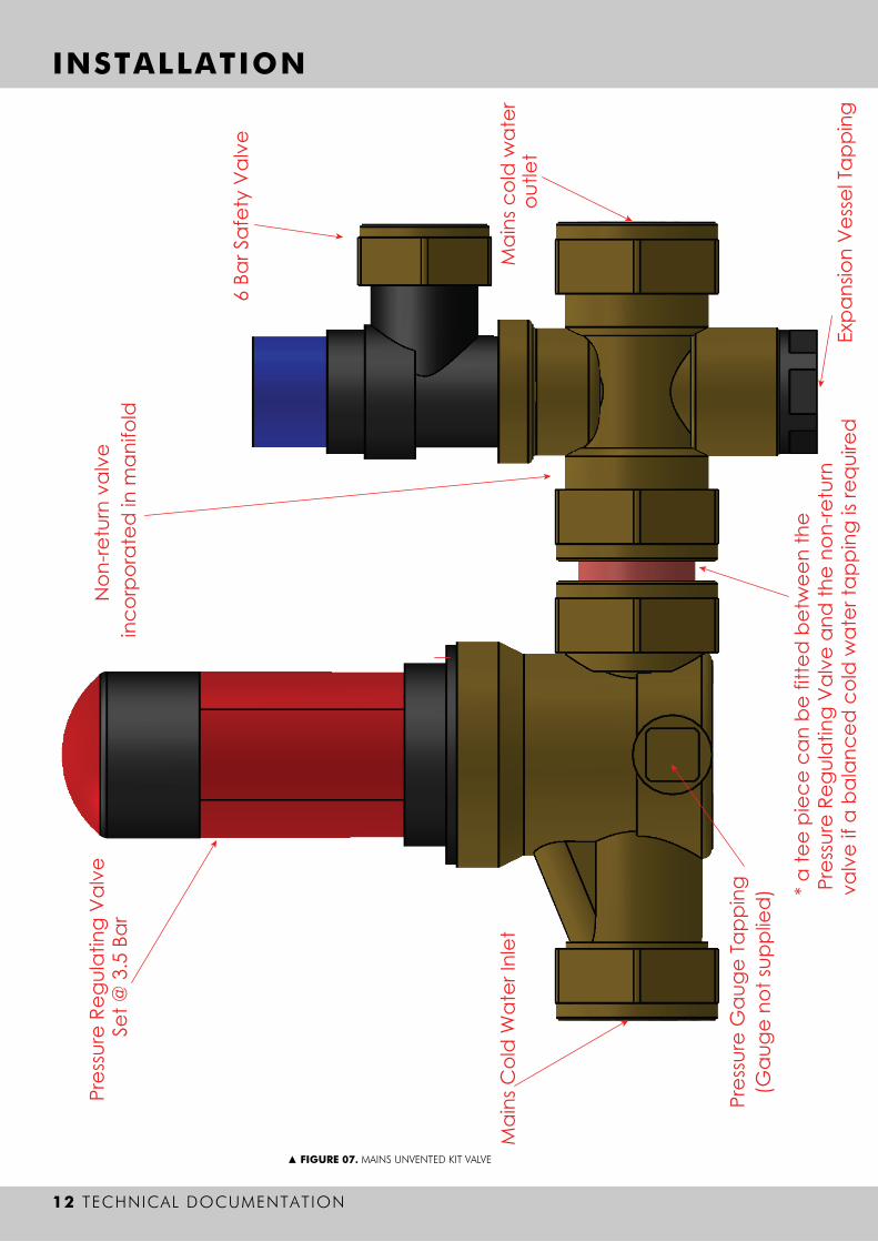
Mai
ns C
old
Wat
er In
let
Pres
sure
Reg
ulat
ing
Val
ve
Set @
3.5
Bar
Pres
sure
Gau
ge T
appi
ng(G
auge
not
supp
lied
)
6 Ba
r Saf
ety
Val
ve
* a
tee
piec
e ca
n be
fitte
d b
etw
een
the
Pre
ssur
e Re
gula
ting
Val
ve a
nd th
e no
n-re
turn
valv
e if
a ba
lanc
ed c
old
wat
er ta
ppin
g is
requ
ired
Expa
nsio
n V
esse
l Tap
ping
Mai
ns c
old
wat
er
outle
t
Non
-retu
rn v
alve
in
corp
orat
ed in
man
ifold
▲ FIGURE 07. MAINS UNVENTED KIT VALVE
INSTALLATION
12 TECHNICAL DOCUMENTATION

▲ FIGURE 08. RAPIDE EXTREMES INSTALLED IN PARALLEL
INSTALLATION
TECHNICAL DOCUMENTATION 13
MULTIPLE EXTREME INSTALLATION
The Rapide Extreme hot water cylinders can be installed in a multiple arrangement but all pipework must be installed in a parallel fashion, or the flow must be arranged to be equal to all cylinders for both primary and secondary water.
Rapide Extreme installed in parallel to ensure equal flow through both units.
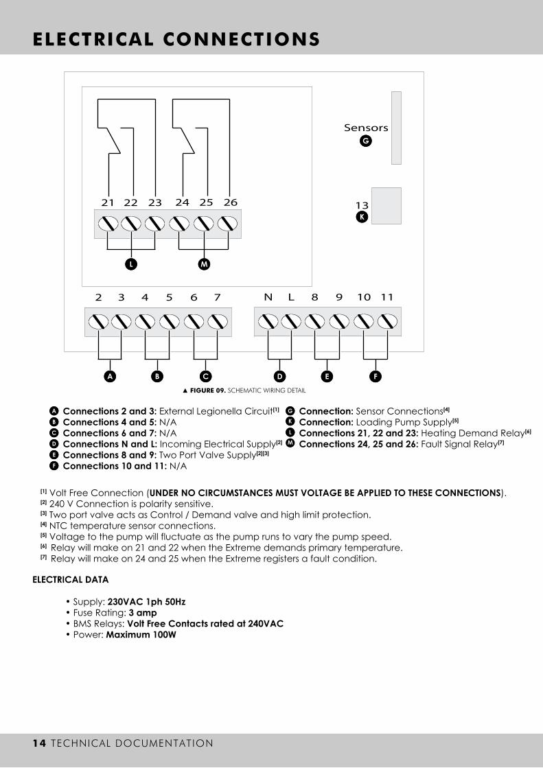
[1] Volt Free Connection (UNDER NO CIRCUMSTANCES MUST VOLTAGE BE APPLIED TO THESE CONNECTIONS).[2] 240 V Connection is polarity sensitive.[3] Two port valve acts as Control / Demand valve and high limit protection.[4] NTC temperature sensor connections.[5] Voltage to the pump will fluctuate as the pump runs to vary the pump speed.[6] Relay will make on 21 and 22 when the Extreme demands primary temperature.[7] Relay will make on 24 and 25 when the Extreme registers a fault condition.
A
B
C
D
E
F
Connections 2 and 3: External Legionella Circuit[1]
Connections 4 and 5: N/A Connections 6 and 7: N/A Connections N and L: Incoming Electrical Supply[2]
Connections 8 and 9: Two Port Valve Supply[2][3]
Connections 10 and 11: N/A
GK
Connection: Sensor Connections[4]
Connection: Loading Pump Supply[5]
Connections 21, 22 and 23: Heating Demand Relay[6]
Connections 24, 25 and 26: Fault Signal Relay[7]
LM
21 22 23 24 25 26
ML
A B C D E F
K
G
2 4 5 63 7 N 8 9 10L 11
13
Sensors
▲ FIGURE 09. SCHEMATIC WIRING DETAIL
ELECTRICAL CONNECTIONS
14 TECHNICAL DOCUMENTATION
ELECTRICAL DATA • • • •
Supply: 230VAC 1ph 50Hz Fuse Rating: 3 ampBMS Relays: Volt Free Contacts rated at 240VACPower: Maximum 100W

Live Connection to Valve from 9 on PCBNeutral Connection to Valve from 8 on PCBEarth Connection to ValveEnd Switch - Normally Closed ConnectionEnd Switch - Normally Open ConnectionEnd Switch - Common Connection
▲ FIGURE 11. SCHEMATIC INSTALLATION DETAIL FOR TWO PORT VALVE
HEAT SOURCE
TWO PORTVALVE
LOADINGPUMP
DHW FLOW
MCW SUPPLY
DHW SECONDARYRETURN
TT 4
TT 2
TT 3
TT 1
▲ FIGURE 10. SCHEMATIC DETAIL FOR SENSOR POSITIONS
ELECTRICAL CONNECTIONS
TECHNICAL DOCUMENTATION 15
NTC SENSOR SCHEMATIC
TWO PORT VALVE WIRING GUIDE
A
B
C
D
E
F
A
B
C
D
E
F

OPERATION
16 TECHNICAL DOCUMENTATION
OPERATING STATUS
To alter the operating mode or requested set point, press the button briefly and the setting will cycle to the next option. Once you have achieved the required setting the unit will automatically adopt the new setting shown on the display.
[1] To achieve the requested set point the primary temperature supplied to the unit MUST be at least 5°C above the set point measured at the primary temperature sensor TT4.
MAINTENANCE
Due to the high quality material used in the manufacture of this product and the simple construction the Rapide Extreme needs no maintenance and enables an exceptionally long guarantee period.
Included in the unit is a service valve on the loading pipe from the base of the cylinder to the plate heat exchanger, this may only be used when the unit is no longer active. Do not close the service valve whilst the unit is operating.
Inspection and cleaning inside the cylinder.
It is possible to clean out the cylinder using fresh mains cold water if so desired. To carry out this operation, isolate and disconnect all water supplies and ensure all electrical supplies are isolated. Run a drain hose from the drain valve to an operating drain, then connect a controlled mains cold water supply to the unit. Drain the unit fully and then slowly supply water to the unit at the rate of drainage. Carry on at this rate until the water running from the bottom of the unit runs clear; then carry out two full fills and drains.
▲ FIGURE 12. OPERATIONS STATUS
DESCRIPTIONThe unit is off and will not attempt to loadThe unit is loading the cylinder to the requested set pointThe unit has achieved the requested set pointUnit requested set point is set to 60°C[1]
Unit requested set point is set to 65°C[1]
Unit requested set point is set to 70°C[1]
The unit is loading the cylinder to the anti-legionella set pointThe unit has achieved the anti-legionella set point
OPERATING STATUSoFnLnRn1n2n3hLhR
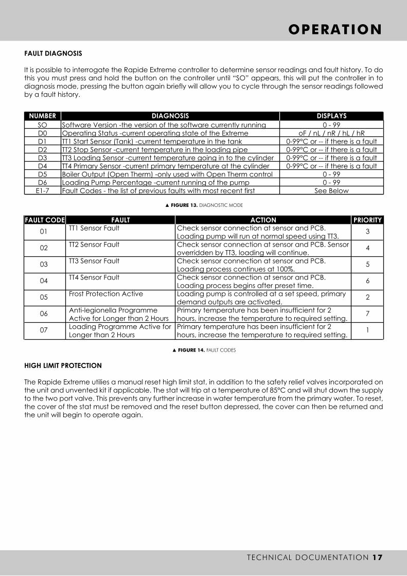
Software Version -the version of the software currently runningOperating Status -current operating state of the Extreme TT1 Start Sensor (Tank) -current temperature in the tankTT2 Stop Sensor -current temperature in the loading pipeTT3 Loading Sensor -current temperature going in to the cylinderTT4 Primary Sensor -current primary temperature at the cylinderBoiler Output (Open Therm) -only used with Open Therm controlLoading Pump Percentage -current running of the pumpFault Codes - the list of previous faults with most recent first
0 - 99oF / nL / nR / hL / hR
0-99°C or -- if there is a fault0-99°C or -- if there is a fault0-99°C or -- if there is a fault0-99°C or -- if there is a fault
0 - 990 - 99
See Below
▲ FIGURE 13. DIAGNOSTIC MODE
SOD0D1D2D3D4D5D6
E1-7
NUMBER DIAGNOSIS DISPLAYS
3
4
5
6
2
7
1
FAULT CODE FAULT ACTION PRIORITY01
02
03
04
05
06
07
TT1 Sensor Fault
TT2 Sensor Fault
TT3 Sensor Fault
TT4 Sensor Fault
Frost Protection Active
Anti-legionella Programme Active for Longer than 2 HoursLoading Programme Active for Longer than 2 Hours
Check sensor connection at sensor and PCB. Loading pump will run at normal speed using TT3.Check sensor connection at sensor and PCB. Sensor overridden by TT3, loading will continue.Check sensor connection at sensor and PCB. Loading process continues at 100%.Check sensor connection at sensor and PCB. Loading process begins after preset time.Loading pump is controlled at a set speed, primary demand outputs are activated.Primary temperature has been insufficient for 2 hours, increase the temperature to required setting.Primary temperature has been insufficient for 2 hours, increase the temperature to required setting.
▲ FIGURE 14. FAULT CODES
OPERATION
TECHNICAL DOCUMENTATION 17
FAULT DIAGNOSIS
It is possible to interrogate the Rapide Extreme controller to determine sensor readings and fault history. To do this you must press and hold the button on the controller until “SO” appears, this will put the controller in to diagnosis mode, pressing the button again briefly will allow you to cycle through the sensor readings followed by a fault history.
HIGH LIMIT PROTECTION
The Rapide Extreme utilies a manual reset high limit stat, in addition to the safety relief valves incorporated on the unit and unvented kit if applicable. The stat will trip at a temperature of 85°C and will shut down the supply to the two port valve. This prevents any further increase in water temperature from the primary water. To reset, the cover of the stat must be removed and the reset button depressed, the cover can then be returned and the unit will begin to operate again.

NOTES
18 TECHNICAL DOCUMENTATION


Mikrofill Systems Ltd. 11 Merse Road, North Moons Moat, Redditch, Worcestershire B98 9HL, UK
North Moons Moat, Redditch, Worcestershire B98 9HL, UK
T +44 (0)3452 60 60 20 F +44 (0)3452 60 60 21 E [email protected] www.mikrofill.com