inorganic nanotubes reinforced polyvinylidene fluoride ...eswaraiah/low cost emi shielding...
TRANSCRIPT

NANO EXPRESS Open Access
Inorganic nanotubes reinforced polyvinylidenefluoride composites as low-cost electromagneticinterference shielding materialsVarrla Eswaraiah1,2, Venkataraman Sankaranarayanan2, Sundara Ramaprabhu1*
Abstract
Novel polymer nanocomposites comprising of MnO2 nanotubes (MNTs), functionalized multiwalled carbonnanotubes (f-MWCNTs), and polyvinylidene fluoride (PVDF) were synthesized. Homogeneous distribution of f-MWCNTs and MNTs in PVDF matrix were confirmed by field emission scanning electron microscopy. Electricalconductivity measurements were performed on these polymer composites using four probe technique. Theaddition of 2 wt.% of MNTs (2 wt.%, f-MWCNTs) to PVDF matrix results in an increase in the electrical conductivityfrom 10-16S/m to 4.5 × 10⁻⁵S/m (3.2 × 10⁻¹S/m). Electromagnetic interference shielding effectiveness (EMI SE) wasmeasured with vector network analyzer using waveguide sample holder in X-band frequency range. EMI SE ofapproximately 20 dB has been obtained with the addition of 5 wt.% MNTs-1 wt.% f-MWCNTs to PVDF incomparison with EMI SE of approximately 18 dB for 7 wt.% of f-MWCNTs indicating the potential use of thepresent MNT/f-MWCNT/PVDF composite as low-cost EMI shielding materials in X-band region.
IntroductionIn recent years, electronics field has diversified in tele-communication systems, cellular phones, high-speedcommunication systems, military devices, wirelessdevices, etc. Due to the increase in use of high operatingfrequency and bandwidth in electronic systems, thereare concerns and more chances of deterioration of theradio wave environment known as electromagneticinterference (EMI). This EMI has adverse effects onelectronic equipments such as false operation due tounwanted electromagnetic waves and leakage of infor-mation in wireless telecommunications [1]. Hence, inorder to maintain the electromagnetic compatibility ofthe end product, light weight EMI shielding materialsare required to sustain the good working environmentof the devices. EMI shielding refers to the reflection orabsorption or multiple reflection of the electromagneticradiation by a shielding material which thereby acts as ashield against the penetration of the radiation through it[2]. Conventionally, metals and metallic composites are
used as EMI shielding materials as they have highshielding efficiency owing to their good electrical con-ductivity. Even though metals are good for EMI shield-ing, they suffer from poor chemical resistance,oxidation, corrosion, high density, and difficulty in pro-cessing [3]. The chemical resistance of polymer isdefined largely by its chemical structure. In the presentcase, polyvinylidene fluoride (PVDF) has been chosen asthe base polymer because of its excellent chemical resis-tance [4,5] over a variety of chemicals, acids, and bases.It is well known that the addition of lower amount ofinorganic nanotubes (1-10 wt.%) will not affect the basicproperties such as chemical resistance, strength, etc. ofthe base polymer [6,7]. Ever since the discovery by Ijima[8], carbon nanotubes (CNT) have attracted consider-able research interest owing to their unique physicaland chemical properties [9,10]. CNT-polymer compo-sites gained popularity recently for various applications[11-13] due to the distinct advantages of polymers andnanofillers (CNT) such as lightweight, resistance to cor-rosion, and chemical resistance of the polymer as wellas high electrical conductivity, high aspect ratio, andhigh mechanical strength of CNT [14,15].Previous studies on CNT-polymer composites show
that carbon nanotubes can be considered as advanced
* Correspondence: [email protected] Energy and Nanotechnology Laboratory (AENL), Nano FunctionalMaterials, Technology Centre (NFMTC), Department of Physics, IndianInstitute of Technology Madras, Chennai 600036, IndiaFull list of author information is available at the end of the article
Eswaraiah et al. Nanoscale Research Letters 2011, 6:137http://www.nanoscalereslett.com/content/6/1/137
© 2011 Eswaraiah et al; licensee Springer. This is an Open Access article distributed under the terms of the Creative CommonsAttribution License (http://creativecommons.org/licenses/by/2.0), which permits unrestricted use, distribution, and reproduction inany medium, provided the original work is properly cited.

reinforcing materials possessing excellent electrical andmechanical properties and their unique one-dimensionalstructure [16,17] make them ideal for creating overlap-ping conductive network for high-performance EMIshielding at low loadings [18-21]. CNT-polymer compo-sites either based on solvent casting or melt-based tech-niques have been studied with various polymer matrices,including PMMA [22], liquid crystal polymers, and mel-amine formaldehydes [23], PVA [24], and fused silica[25] for various applications such as radiation protec-tion, EMI shielding, and electrostatic discharge materi-als. There are many reports on EMI shielding of carbonnanotubes reinforced polymer composites [26-30] in theX-band region because of its use in military communi-cation satellites, weather monitoring, air traffic control,defense trackingand high-resolution imaging radars. Butthe disadvantage is the high loading of carbon nano-tubes which is at present economically not feasible. So,there is a critical need for the development of low-costEMI shielding materials at this particular frequency.Yonglai et al. [31] reported low-cost EMI shieldingmaterials with the combination of carbon nanofiber andcarbon nanotube composites in polystyrene (PS) matrix.They could achieve electromagnetic interference shield-ing effectiveness (EMI SE) of 20 dB for the combinationof 10 wt.% carbon nanofiber and 1 wt.% carbon nano-tubes in PS matrix in the range 12-18 GHz. In the pre-sent study, we have developed a low-cost hybrid EMIshielding material comprising of manganese dioxidenanotubes and low loading of multiwalled carbon nano-tubes (MWCNTs) in PVDF matrix. EMI shielding effi-ciency and electrical conductivity of the composites withdifferent weight fractions of functionalized multiwalledcarbon nanotubes (f-MWCNTs) and MnO2 nanotubes(MNTs) were investigated to optimize polymer compo-sites with less content of carbon nanotubes that exhibitenhanced electrical properties and serve as a better EMIshielding material. The focus of the present work is tofill the space between the MNTs using a low weightpercent of f-MWCNTs within the polymer matrix andthereby making utmost use of the advantages off-MWCNTs and eventually achieve low-cost andimproved EMI shielding materials.
Experimental sectionMaterialsPVDF was used as polymer matrix with a molecularweight of 100,000 g.mol and it was purchased from AlfaAesar. MWCNTs were synthesized by chemical vapordeposition technique. MNTs were prepared by hydro-thermal route and N,N-dimethyl formamide was used asthe solvent for carbon nanotubes and MnO2 nanotubes.Laboratory grade acids, bases, and organic solvents wereused.
Synthesis of functionalized multiwalled carbon nanotubesMWCNTs were synthesized by chemical vapor deposi-tion technique using misch metal (approximately 50%cerium and 25% lanthanum, with small amounts of neo-dymium and praseodymium)-based AB3 alloy hydridecatalysts [32]. The as-grown MWCNTs not only containpure MWCNTs but also amorphous carbon, fullerenes,and other metal catalysts. In order to remove these cata-lytic impurities and amorphous carbon, air oxidationwas performed at 350°C for 4 h followed by acid treat-ment in concentrated HNO3. After purification,MWCNTs were functionalized with 3:1 ratio of H2SO4
and HNO3 at 60°C for 6 h in order to impart hydroxyland carboxyl functional groups over the side walls.
Synthesis of MnO2 nanotubesMNTs were prepared by hydrothermal route [33]. Briefly,0.608 g of KMnO4 and 1.27 ml of HCl (37 wt.%) wereadded to 70 ml of de-ionized water with continuous stir-ring to form the precursor solution. After stirring, thesolution was transferred to a teflon lined stainless steelautoclave with a capacity of 100 ml. The autoclave waskept in an oven at 140°C for 12 h and then cooled downto room temperature. The resulting brown precipitatewas collected, rinsed, and filtered to a pH 7. The as-pre-pared powders were then dried at 80°C in air.
Synthesis of f-MWCNTs-MNTs-PVDF compositesMNTs and f-MWCNTs reinforced polymer matrix com-posites were prepared by mixing the respective compo-site solutions at high-speed rotations per minutefollowed by solvent casting. Here, we describe themethod of preparation of the composites. Initially, 10mg of MNTs and 990 mg of polymer were dispersedseparately in dimethylformamide (DMF) with the helpof an ultrosonicator for 1 h at room temperature for thepreparation of 1 wt.% MNTs in polymer matrix. Thesetwo solutions were mixed by sonicating together for 1 hand the composite solution was transferred to a meltmixer and stirred at room temperature at 4,000 rpm for2 h and at 80°C for 30 min. The resulting solution wastransferred into the beaker and kept in an oven toremove the solvent. Finally, dried thin films were put ina mold and pressed to form 1-mm thick structures. Asimilar procedure was followed for the preparationof functionalized multiwalled carbon nanotubes (f-MWCNTs)/PVDF composite films. For the preparationof f-MWCNTs/MNTs/PVDF composite, fixed amountof MNTs, f-MWCNTs, and PVDF were added to DMFseparately for a desired composition, and the above-mentioned procedure was followed to prepare the com-posite films. A series of composites were prepared in asimilar way by varying the amount of polymer, MNTs,and MWCNTs.
Eswaraiah et al. Nanoscale Research Letters 2011, 6:137http://www.nanoscalereslett.com/content/6/1/137
Page 2 of 11

CharacterizationThe direct current (DC) volume electrical conductivityof the composites was measured at room temperatureusing homemade resistivity setup with the help of Keith-ley 2400 sourcemeter and 2182 nanovoltmeter. The highresistance of the films was measured with a 617 pro-grammable electrometer and a 6517B high-resistanceelectrometer. The EMI shielding measurement was per-formed with an Agilent E8362B vector network analyzerusing a 201-point averaging in the frequency range of 8to 12 GHz (X-band). Figure 1 shows the pictorial repre-sentation of the experimental setup for measuring theshielding effectiveness of the composite materials. Here,we followed the transmission line technique using an X-band waveguide sample holder for measuring scatteringparameters of the composites. Samples of dimensions22.84 × 10.16 mm2 were prepared and kept inside thewaveguide. The EMI shielding effectiveness is defined asthe ratio of incoming (Pi) to outgoing power (Po) ofradiation. Shielding effectiveness (SE) = 10 log (Pi/Po)and is defined in decibels (dB). The higher the value indecibels, the less energy passes through the material.When electromagnetic radiation falls on the shieldingmaterial, reflection, absorption, and transmissionare observed. The corresponding reflectivity (R), absorp-tivity (A), and transmissivity (T) are according to theequation A + R + T = 1. R and T can be calculatedfrom the measured scattering coefficients, from the rela-tions S12 = 10 log T and S11 = 10 log R. The cross-sec-tional morphology of the composites were observedusing field emission scanning electron microscope(FESEM, QUANTA 3 D, FEI) and transmission electron
microscope. X-ray elemental mapping was also per-formed using EDX genesis software. Powder X-ray dif-fraction (XRD) studies were carried out using X’PertPRO, PANalytical diffractometer with nickel filter CuKa radiation as the X-ray source. The samples werescanned in steps of 0.016° in the 2θ range 10 to 80. Forthe determination of functional groups, a Fourier trans-form infrared spectrum was acquired using PerkinElmer FTIR spectrometer from 400 to 4,000 cm-1. Thechemical resistance of the composites in different acids,bases, alkanes and organic solvents was estimated bymeasuring the weight of the sample before and aftertreatment with these chemicals using METTLERTOLEDO XS 105 weighing balance.
Results and discussionX-ray diffraction analysisThe crystal structure of polymer, MNTs, and f-MWCNTs has been investigated by powder X-ray dif-fraction. Figure 2 shows the XRD pattern of the PVDF,f-MWCNTs, and MNTs. Figure 2a shows the XRD pat-tern of f-MWCNTs in which the peaks are indexed tothe reflections of hexagonal graphite. The absence ofadditional peaks corresponding to the catalytic impuri-ties confirms that the impurities have been removed bythe acid treatment. The XRD spectrum of the as-synthe-sized MNT is shown in Figure 2b. All the diffractionpeaks can be indexed according to the a-MnO2 phase,and no other characteristic peaks from any impurity areobserved. This establishes the high purity of the sample.In Figure 2c, it can be seen that pure PVDF membraneis crystalline in nature with visible peaks at 18.65° and
Figure 1 Experimental setup for EMI shielding characteristic measurements of polymer composites.
Eswaraiah et al. Nanoscale Research Letters 2011, 6:137http://www.nanoscalereslett.com/content/6/1/137
Page 3 of 11
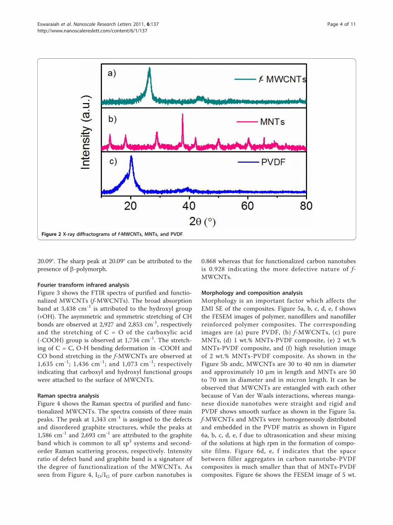
20.09°. The sharp peak at 20.09° can be attributed to thepresence of b-polymorph.
Fourier transform infrared analysisFigure 3 shows the FTIR spectra of purified and functio-nalized MWCNTs (f-MWCNTs). The broad absorptionband at 3,438 cm-1 is attributed to the hydroxyl group(νOH). The asymmetric and symmetric stretching of CHbonds are observed at 2,927 and 2,853 cm-1, respectivelyand the stretching of C = O of the carboxylic acid(-COOH) group is observed at 1,734 cm-1. The stretch-ing of C = C, O-H bending deformation in -COOH andCO bond stretching in the f-MWCNTs are observed at1,635 cm-1; 1,436 cm-1; and 1,073 cm-1; respectivelyindicating that carboxyl and hydroxyl functional groupswere attached to the surface of MWCNTs.
Raman spectra analysisFigure 4 shows the Raman spectra of purified and func-tionalized MWCNTs. The spectra consists of three mainpeaks. The peak at 1,343 cm-1 is assigned to the defectsand disordered graphite structures, while the peaks at1,586 cm-1 and 2,693 cm-1 are attributed to the graphiteband which is common to all sp2 systems and second-order Raman scattering process, respectively. Intensityratio of defect band and graphite band is a signature ofthe degree of functionalization of the MWCNTs. Asseen from Figure 4, ID/IG of pure carbon nanotubes is
0.868 whereas that for functionalized carbon nanotubesis 0.928 indicating the more defective nature of f-MWCNTs.
Morphology and composition analysisMorphology is an important factor which affects theEMI SE of the composites. Figure 5a, b, c, d, e, f showsthe FESEM images of polymer, nanofillers and nanofillerreinforced polymer composites. The correspondingimages are (a) pure PVDF, (b) f-MWCNTs, (c) pureMNTs, (d) 1 wt.% MNTs-PVDF composite, (e) 2 wt.%MNTs-PVDF composite, and (f) high resolution imageof 2 wt.% MNTs-PVDF composite. As shown in theFigure 5b andc, MWCNTs are 30 to 40 nm in diameterand approximately 10 μm in length and MNTs are 50to 70 nm in diameter and in micron length. It can beobserved that MWCNTs are entangled with each otherbecause of Van der Waals interactions, whereas manga-nese dioxide nanotubes were straight and rigid andPVDF shows smooth surface as shown in the Figure 5a.f-MWCNTs and MNTs were homogeneously distributedand embedded in the PVDF matrix as shown in Figure6a, b, c, d, e, f due to ultrasonication and shear mixingof the solutions at high rpm in the formation of compo-site films. Figure 6d, e, f indicates that the spacebetween filler aggregates in carbon nanotube-PVDFcomposites is much smaller than that of MNTs-PVDFcomposites. Figure 6e shows the FESEM image of 5 wt.
Figure 2 X-ray diffractograms of f-MWCNTs, MNTs, and PVDF.
Eswaraiah et al. Nanoscale Research Letters 2011, 6:137http://www.nanoscalereslett.com/content/6/1/137
Page 4 of 11
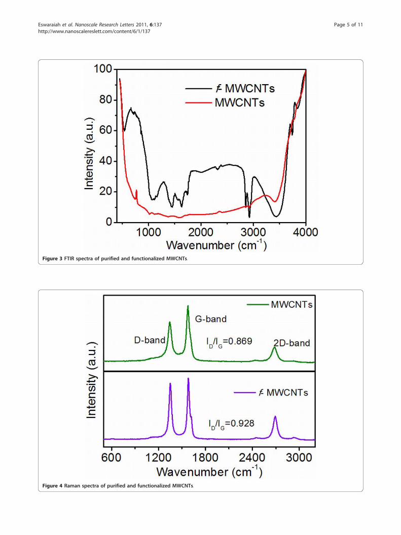
Figure 3 FTIR spectra of purified and functionalized MWCNTs.
Figure 4 Raman spectra of purified and functionalized MWCNTs.
Eswaraiah et al. Nanoscale Research Letters 2011, 6:137http://www.nanoscalereslett.com/content/6/1/137
Page 5 of 11

% MNTs filled PVDF composite along with 1 wt.%MWCNTs. It is observed that a very good microstruc-ture has been formed, and f-MWCNTs were uniformlydispersed and embedded between the MNTs throughoutthe PVDF matrix. This good network can increase the
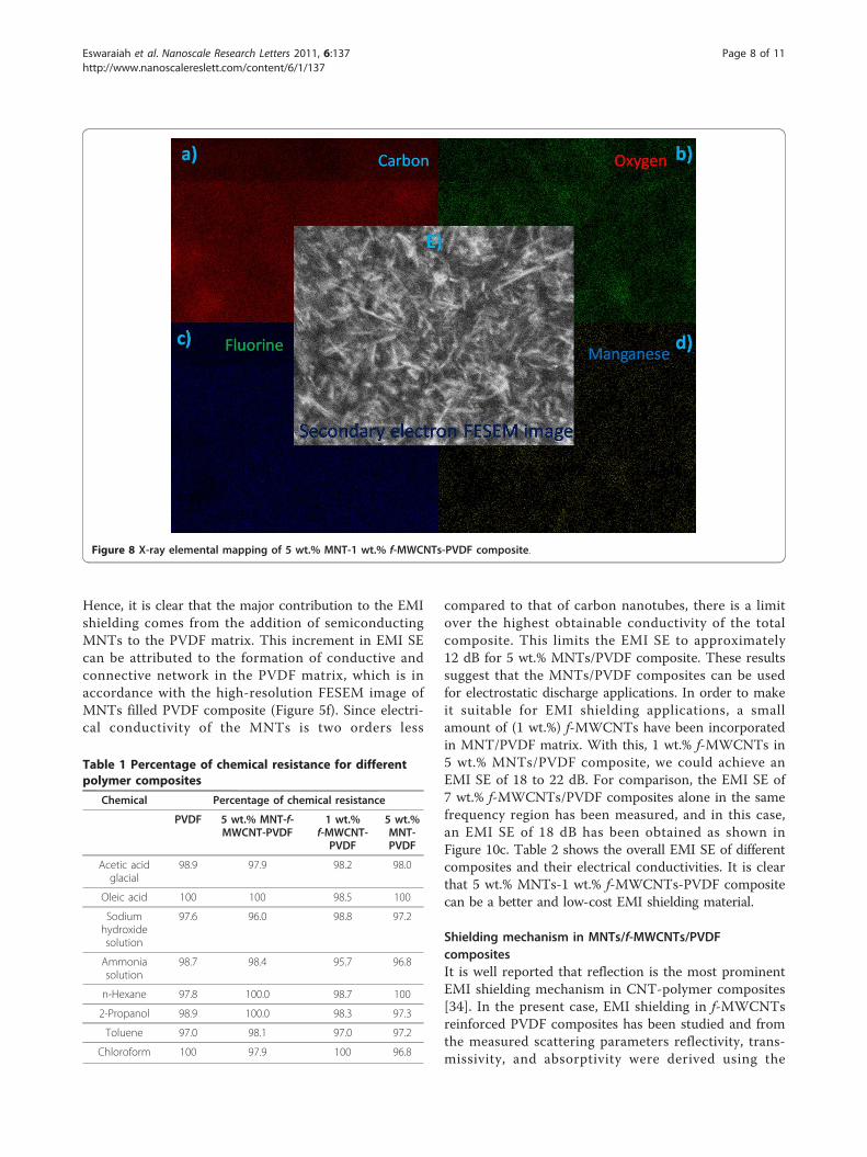
number of inter nanostructure connections, and henceprovide better EMI SE. Further, to confirm the homoge-neity of the composites, we have performed X-ray ele-mental mapping over the sample surface to visualize theatomic elements of manganese, oxygen, carbon, and
Figure 5 Field emission scanning electron microscope images. (a) PVDF, (b) f-MWCNTs, (c) MNTs, (d) 1 wt.% MNTs-PVDF, (e) 2 wt.% MNTs-PVDF, and (f) high-resolution image of 2 wt.% f-MWCNTs-PVDF.
Figure 6 Field emission scanning electron microscope images. (a) 3 wt.% MNTs-PVDF, (b) 4 wt.% MNTs-PVDF, (c) 5 wt.% MNTs-PVDF, (d) 1wt.% f-MWCNTs-5 wt.% MNTs-PVDF, and (e) 2 wt.% f-MWCNTs-5 wt.% MNTs-PVDF, and (f) high-resolution image of 1 wt.% f-MWCNTs-5 wt.%MNTs-PVDF.
Eswaraiah et al. Nanoscale Research Letters 2011, 6:137http://www.nanoscalereslett.com/content/6/1/137
Page 6 of 11

fluorine. Figure 7 shows the EDX spectra of PVDF-based MNTs and f-MWCNTs composite. It confirmsthe presence of manganese and oxygen from MnO2, car-bon from f-MWCNTs, and fluorine from the PVDFpolymer. Figure 8 shows the elemental mapping of the 5wt.% MNTs-1 wt.% f-MWCNTs-PVDF composite. Ascan be seen from the figures, all the elements were dis-tributed homogeneously in the polymer matrix.
Chemical resistance of the polymer compositesThe percentage of chemical resistance of the compositesin different acids, bases, organic solvents, and alkanesare shown in the Table 1. It indicates that all the poly-mer composites are highly resistant towards the chemi-cals. The MNT-MWCNTs-PVDF composite shows 95%to 100% resistance towards chemicals which indicatesthe potentiality of the present composite. For compari-son, the chemical resistances of MWCNT-PVDF, PVDF,and MNT-PVDF composites were also measured.
Electrical conductivity analysisElectrical conductivity is of utmost importance for effec-tive EMI shielding material. As shown in the Figure 9,the conductivity of the PVDF is about 10-16S/m. As theconcentration of the MNTs increases in the PVDFmatrix, electrical conductivity increases, and it followspercolation behavior. Conductivity of the 1 wt.% MNTs/PVDF composite was found to be approximately 10-6S/m, which indicates that there is a drastic improvementin electrical conductivity. An increase of about ten
orders of magnitude of electrical conductivity wasobserved which can be attributed to the high aspectratio and efficient dispersion of the MNTs in the PVDFmatrix. Similar trend is observed in the case of electricalconductivity of the f-MWCNTs/PVDF composites asshown in Figure 9b. The possible mechanism for theincrement in the electrical conductivity of the compo-sites can be the tunneling effect of the electrons fromone nanotube to the other. The effect of f-MWCNTscontent on the electrical conductivity of the MNTs/PVDF composites was studied. Incorporation of 1 wt.%f-MWCNTs in 5 wt.% MNT/PVDF composites increasesthe conductivity from 10-5S/m to approximately 10-1S/mwhich can be attributed to the high aspect ratio, homo-geneous dispersion, and high electrical conducting nat-ure of the f-MWCNTs.
Electromagnetic interference shielding effectivenessThe EMI SE of MNTs/PVDF composites with variousmass fractions of MNTs as a function of frequency arepresented in Figure 10a. The results show that EMIshielding effectiveness of pure PVDF is almost 0.3 dBindicating that it is transparent to the electromagneticradiation throughout the measured frequency. This isprobably due to its electrically insulating nature. It isobserved that EMI SE starts increasing with the additionof MNTs to the insulating PVDF matrix. The EMI SEfor 1 wt.% MNTs filled PVDF composite is found to be2.27 dB and it increases further to 5.14 and 11 dB athigher loading of MNTs of 3 and 5 wt.%, respectively.
Figure 7 Energy dispersive X-ray spectra of MnO2 nanotubes and its composites.
Eswaraiah et al. Nanoscale Research Letters 2011, 6:137http://www.nanoscalereslett.com/content/6/1/137
Page 7 of 11
Hence, it is clear that the major contribution to the EMIshielding comes from the addition of semiconductingMNTs to the PVDF matrix. This increment in EMI SEcan be attributed to the formation of conductive andconnective network in the PVDF matrix, which is inaccordance with the high-resolution FESEM image ofMNTs filled PVDF composite (Figure 5f). Since electri-cal conductivity of the MNTs is two orders less
compared to that of carbon nanotubes, there is a limitover the highest obtainable conductivity of the totalcomposite. This limits the EMI SE to approximately12 dB for 5 wt.% MNTs/PVDF composite. These resultssuggest that the MNTs/PVDF composites can be usedfor electrostatic discharge applications. In order to makeit suitable for EMI shielding applications, a smallamount of (1 wt.%) f-MWCNTs have been incorporatedin MNT/PVDF matrix. With this, 1 wt.% f-MWCNTs in5 wt.% MNTs/PVDF composite, we could achieve anEMI SE of 18 to 22 dB. For comparison, the EMI SE of7 wt.% f-MWCNTs/PVDF composites alone in the samefrequency region has been measured, and in this case,an EMI SE of 18 dB has been obtained as shown inFigure 10c. Table 2 shows the overall EMI SE of differentcomposites and their electrical conductivities. It is clearthat 5 wt.% MNTs-1 wt.% f-MWCNTs-PVDF compositecan be a better and low-cost EMI shielding material.
Shielding mechanism in MNTs/f-MWCNTs/PVDFcompositesIt is well reported that reflection is the most prominentEMI shielding mechanism in CNT-polymer composites[34]. In the present case, EMI shielding in f-MWCNTsreinforced PVDF composites has been studied and fromthe measured scattering parameters reflectivity, trans-missivity, and absorptivity were derived using the
Figure 8 X-ray elemental mapping of 5 wt.% MNT-1 wt.% f-MWCNTs-PVDF composite.
Table 1 Percentage of chemical resistance for differentpolymer composites
Chemical Percentage of chemical resistance
PVDF 5 wt.% MNT-f-MWCNT-PVDF
1 wt.%f-MWCNT-
PVDF
5 wt.%MNT-PVDF
Acetic acidglacial
98.9 97.9 98.2 98.0
Oleic acid 100 100 98.5 100
Sodiumhydroxidesolution
97.6 96.0 98.8 97.2
Ammoniasolution
98.7 98.4 95.7 96.8
n-Hexane 97.8 100.0 98.7 100
2-Propanol 98.9 100.0 98.3 97.3
Toluene 97.0 98.1 97.0 97.2
Chloroform 100 97.9 100 96.8
Eswaraiah et al. Nanoscale Research Letters 2011, 6:137http://www.nanoscalereslett.com/content/6/1/137
Page 8 of 11
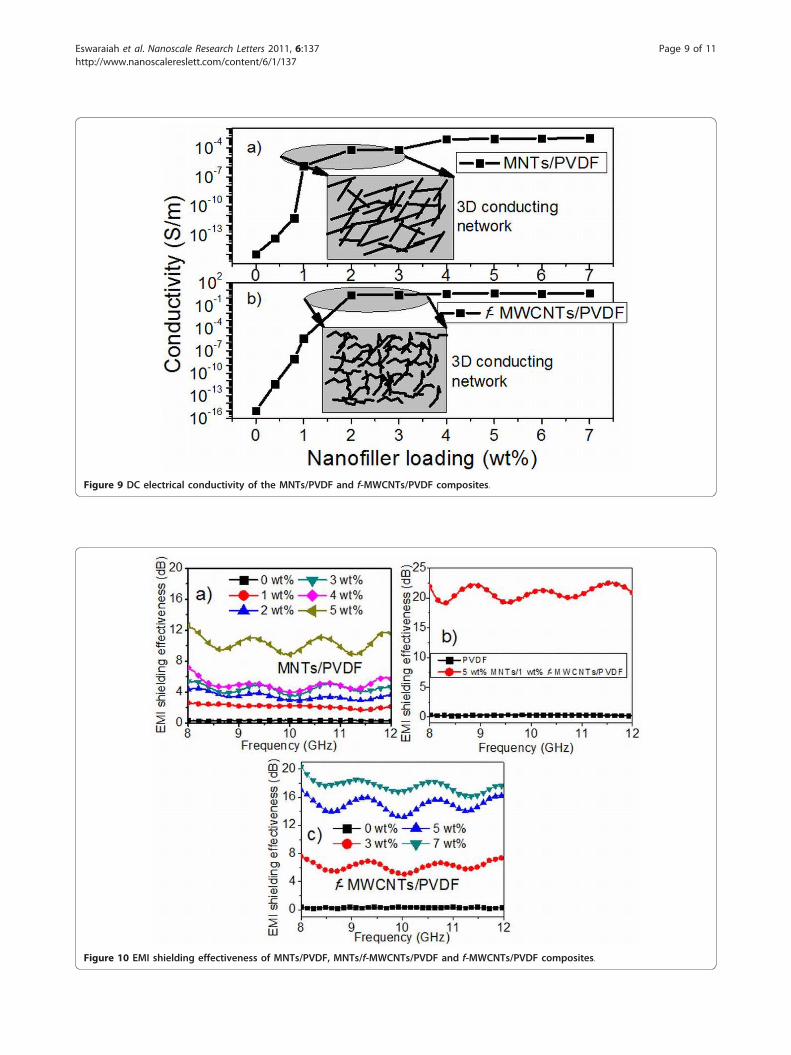
Figure 9 DC electrical conductivity of the MNTs/PVDF and f-MWCNTs/PVDF composites.
Figure 10 EMI shielding effectiveness of MNTs/PVDF, MNTs/f-MWCNTs/PVDF and f-MWCNTs/PVDF composites.
Eswaraiah et al. Nanoscale Research Letters 2011, 6:137http://www.nanoscalereslett.com/content/6/1/137
Page 9 of 11

formulae mentioned in the experimental section. For 5wt.% f-MWCNT-PVDF composites, the transmissivity,reflectivity, and absorptivity are 0.177, 0.601, and 0.222,respectively and the corresponding parameters for7 wt.% f-MWCNT-PVDF composites are 0.131, 0.794,and 0.075. From these results, we can conclude thatreflection is the major EMI shielding mechanism in thepresent f-MWCNT-PVDF composites. This may be dueto the presence of conjugated π electrons on the surfaceof f-MWCNTs. In the case of MNTs/PVDF composites,the chances of absorbing incident radiation are moredue to the presence of electric dipoles. Table 3 gives acomparison of the reflectivity and absorptivity of variouscomposites. It is observed that f-MWCNTs/MNTs/PVDF composites and MNTs/PVDF composites exhibitmore absorption than reflection. For 5 wt.% MNTs/1 wt.% f-MWCNTs/PVDF composite, the absorptivity,transmissivity, and reflectivity values are respectively0.78, 0.01, and 0.210. Based on the measured fundamen-tal properties of MNTs/PVDF, f-MWCNTs/PVDF, andMNTs/f-MWCNTs/PVDF composites, the present com-posites can be engineered for reflection to absorption ofthe incoming EM radiation by varying the amount ofcarbon nanotubes and MnO2 nanotubes in the polymer
matrix. The incorporation of MNTs in f-MWCNT-PVDF composite helps in overcoming the Van derWaals forces between f-MWCNTs while utilizing thehigh aspect ratio of them. Another advantage of theaddition of MNTs is that it could decrease the amountof f-MWCNT loading in PVDF matrix.
ConclusionNovel hybrid nanofiller consisting of multiwalled carbonnanotubes and MnO2 nanotubesreinforced PVDF com-posite has been fabricated and proposed as an efficientmaterial for EMI shielding applications. MNTs and f-MWCNTs acting as spacers in PVDF matrix helps inreducing the aggregation of the nanofillers and createsan excellent 3 D conducting network in the polymer.MNTs are acting as very good filler material whenadded to the entangled carbon nanotubes incorporatedpolymer. An EMI shielding effectiveness of approxi-mately 20 dB has been achieved with 5 wt.% MNTs and1 wt.% f-MWCNTs in polymer matrix in X-band region.The increase in EMI shielding effectiveness with theaddition of nanofillers is attributed to the enhancedelectrical conductivity of the composite due to the addi-tion of f-MWCNTs and good homogeneity of the nano-fillers in the polymer. The present hybrid polymernanocomposites are proposed as low-cost and efficientEMI shielding materials in X-band region.
AcknowledgementsThis work was supported by IIT Madras and the authors thank theDepartment of Science and Technology (DST), India for financial support.One of the authors (V. ESWARAIAH) thanks Dr. Harishankar Ramachandran,professor, Microwave Lab, Department of Electrical Engineering, IIT Madrasfor helping in EMI shielding measurements.
Author details1Alternative Energy and Nanotechnology Laboratory (AENL), Nano FunctionalMaterials, Technology Centre (NFMTC), Department of Physics, IndianInstitute of Technology Madras, Chennai 600036, India 2Low TemperaturePhysics Laboratory, Department of Physics, Indian Institute of TechnologyMadras, Chennai 600036, India
Authors’ contributionsVER carried out the composites preparation, other characterizations andwritten the manuscript. VSN and SRP are conceived in its coordination. Allauthors read and approved the final manuscript.
Competing interestsThe authors declare that they have no competing interests.
Received: 10 October 2010 Accepted: 14 February 2011Published: 14 February 2011
References1. Imai M, Akiyama K, Tanaka T, Sano E: Highly strong and conductive
carbon nanotube/cellulose composite paper. Compos Sci Technol 2010,70:1564.
2. Chung DDL: Electromagnetic interference shielding effectiveness ofcarbon materials. Carbon 2001, 39:279.
3. Azim SS, Satheesh A, Ramu KK, Ramu S, Venkatachari G: Studies ongraphite based conductive paint coatings. Prog Org Coat 2006, 55:1.
Table 2 Electrical conductivity and EMI SE of the polymercomposites
Composite Electricalconductivity
(S/m)
EMI SE(dB)
1 wt.% f-MWCNTs/PVDF Approximately 10-10 Approximately 2
2 wt.% f-MWCNTs/PVDF Approximately 10-1 Approximately 7
5 wt.% MNTs/PVDF Approximately 10-5 Approximately 11
7 wt% f-MWCNTs/PVDF Approximately 10-1 Approximately 18
5 wt.% MNTs/1 wt.%f-MWCNTs/PVDF
Approximately 10-1 Approximately 21
5 wt.% MNTs/2 wt.%f-MWCNTs/PVDF
Approximately 10-1 Approximately 20
Table 3 Transmissivity, reflectivity, and absorptivity ofMNTs/f-MWCNTs/PVDF composites
Composite Absorptivity Transmissivity Reflectivity
1 wt.% f-MWCNTs/PVDF 0.042 0.631 0.327
2 wt.% f-MWCNTs/PVDF 0.218 0.199 0.583
5 wt.% f-MWCNTs-PVDF 0.222 0.177 0.601
7 wt.% f-MWCNTs-PVDF 0.075 0.131 0.794
5 wt.% MNT-PVDF 0.530 0.1 0.370
7 wt.% MNT-PVDF 0.608 0.1 0.292
5 wt% MNT-1 wt.%f-MWCNTs-PVDF
0.780 0.01 0.210
7 wt% MNT-1 wt.%f-MWCNTs-PVDF
0.796 0.01 0.194
Eswaraiah et al. Nanoscale Research Letters 2011, 6:137http://www.nanoscalereslett.com/content/6/1/137
Page 10 of 11

4. Database for chemical resistance of PVDF. [http://www.zeusinc.com/technicalservices/technicalbulletins/chemicalresistanceofpolymers/chemicalresistancechartpvdf.aspx].
5. Steller J, Krella A, Koronowicz J, Janicki W: Towards quantitativeassessment of material resistance to cavitation erosion. Wear 2005,258:604.
6. Wu M, Shaw LL: On the improved properties of injection-molded, carbonnanotube-filled PET/PVDF blends. J Power Sources 2004, 136:37.
7. Lee Y-B, Lee C-H, Lim D-S: The electrical and corrosion properties ofcarbon nanotube coated 304 stainless steel/polymer composite as PEMfuel cell bipolar plates. Int J Hydrogen Energy 2009, 34:9781.
8. Iijima S: Helical microtubules of graphitic carbon. Nature 1991, 354:56.9. Tersoff J, Ruoff RS: Structural Properties of a Carbon-Nanotube Crystal.
Phys Rev Lett 1994, 73:676.10. O’Connell MJ: Carbon nanotubes: Properties and Applications Routledge:
Taylor and Francis; 2006.11. Barick AK, Tripathy DK: Effect of nanofiber on material properties of
vapor-grown carbon nanofiber reinforced thermoplastic polyurethane(TPU/CNF) nanocomposites prepared by melt compounding. ComposPart A 2010, 41:1471.
12. Salvatierra RV, Oliveira MM, Zarbin AJG: One-Pot Synthesis and Processingof Transparent, Conducting, and Freestanding Carbon Nanotubes/Polyaniline Composite Films. Chem Mater 2010, 22:5222.
13. Singh I, Madhwal D, Verma A, Kumar A, Rait S, Kaur I, Bharadwaj LM,Bhatia CS, Bhatnagar PK, Mathur PC: Enhanced luminance of MEH-PPVbased PLEDs using single walled carbon nanotube composite as anelectron transporting layer. J Lumin 2010, 130:2157.
14. Cheng KB, Ramakrishna S, Lee KC: Electromagnetic shielding effectivenessof copper/glass fiber knitted fabric reinforced polypropylenecomposites. Compos Part A 2000, 31:1039.
15. Kaynak A: Electromagnetic shielding effectiveness of galvanostaticallysynthesized conducting polypyrrole films in the 300-2000 MHzfrequency range. Mater Res Bull 1996, 31:845.
16. Coleman JN, Khan U, Blau WJ, Gun’ko YK: Small but strong: A review ofthe mechanical properties of carbon nanotube-polymer composites.Carbon 2006, 44:1624.
17. Chen C, Lu Y, Kong ES, Zhang Y, Lee ST: Nanowelded Carbon-Nanotube-Based Solar Microcells. Small 2008, 4:1313.
18. Al-Saleh MH, Sundararaj U: Electromagnetic interference shieldingmechanisms of CNT/polymer composites. Carbon 2009, 47:1738.
19. Han MS, Lee YK, Lee HS, Yun CH, Kim WN: Electrical, morphological andrheological properties of carbon nanotube composites withpolyethylene and poly(phenylene sulfide) by melt mixing. Chem Eng Sci2009, 64:4649.
20. Panwar V, Kang B, Park JO, Park S, Mehra RM: Study of dielectric propertiesof styrene-acrylonitrile graphite sheets composites in low and highfrequency region. Eur Polym J 2009, 45:1777.
21. Panwar V, Park JO, Park SH, Kumar S, Mehra RM: Electrical, dielectric, andelectromagnetic shielding properties of polypropylene-graphitecomposites. J Appl Polym Sci 2010, 115:1306.
22. Chen LM, Ozisik R, Schadler LS: The influence of carbon nanotube aspectratio on the foam morphology of MWNT/PMMA nanocomposite foams.Polymer 2010, 51:2368.
23. Jou W-S, Cheng H-Z, Hsu C-F: The electromagnetic shielding effectivenessof carbon nanotubes polymer composites. J Alloys Compd 2007, 434:641.
24. Yun J, Im JS, Lee Y-S, Kim H-I: Effect of oxyfluorination onelectromagnetic interference shielding behavior of MWCNT/PVA/PAAccomposite microcapsules. Eur Polym J 2010, 46:900.
25. Xiang C, Pan Y, Guo J: Electromagnetic interference shieldingeffectiveness of multiwalled carbon nanotube reinforced fused silicacomposites. Ceram Int 2007, 33:1293.
26. Li Y, Chen C, Zhang S, Ni Y, Huang J: Electrical conductivity andelectromagnetic interference shielding characteristics of multiwalledcarbon nanotube filled polyacrylate composite films. Appl Surf Sci 2008,254:5766.
27. Mathur RB, Pande S, Singh BP, Dhami TL: Electrical and mechanicalproperties of multi-walled carbon nanotubes reinforced PMMA and PScomposites. Polym Compos 2008, 29:717.
28. Pande S, Singh BP, Mathur RB, Dhami TL, Saini P, Dhawan SK: ImprovedElectromagnetic Interference Shielding Properties of MWCNT-PMMAComposites Using Layered Structures. Nanoscale Res Lett 2009, 4:327.
29. Li Y, Chen CX, Li JT, Zhang S, Ni YW, Cai S, Huang J: Enhanced DielectricConstant for Efficient Electromagnetic Shielding Based on Carbon-Nanotube-Added Styrene Acrylic Emulsion Based Composite. NanoscaleRes Lett 2010, 5:1170.
30. Yang YL, Gupta MC, Dudley KL, Lawrence RW: A comparative study of EMIshielding properties of carbon nanofiber and multi-walled carbonnanotube filled polymer composites. J Nanosci Nanotechnol 2005, 5:927.
31. Yang Y, Gupta MC, Dudley KL: Towards cost-efficient EMI shieldingmaterials using carbon nanostructure-based nanocomposites.Nanotechnology 2007, 18:345701.
32. Reddy ALM, Shaijumon MM, Ramaprabhu S: Alloy hydride catalyst routefor the synthesis of single-walled carbon nanotubes, multi-walledcarbon nanotubes and magnetic metal-filled multi-walled carbonnanotubes. Nanotechnology 2006, 17:5299.
33. Xiao W, Xia H, Fuh JYH, Lu L: Growth of single-crystal [alpha]-MnO2nanotubes prepared by a hydrothermal route and their electrochemicalproperties. J Power Sources 2009, 193:935.
34. Li N, Huang Y, Du F, He XB, Lin X, Gao HJ, Ma YF, Li FF, Chen YS,Eklund PC: Electromagnetic Interference (EMI) Shielding of Single-WalledCarbon Nanotube Epoxy Composites. Nano Lett 2006, 6:1141.
doi:10.1186/1556-276X-6-137Cite this article as: Eswaraiah et al.: Inorganic nanotubes reinforcedpolyvinylidene fluoride composites as low-cost electromagneticinterference shielding materials. Nanoscale Research Letters 2011 6:137.
Submit your manuscript to a journal and benefi t from:
7 Convenient online submission
7 Rigorous peer review
7 Immediate publication on acceptance
7 Open access: articles freely available online
7 High visibility within the fi eld
7 Retaining the copyright to your article
Submit your next manuscript at 7 springeropen.com
Eswaraiah et al. Nanoscale Research Letters 2011, 6:137http://www.nanoscalereslett.com/content/6/1/137
Page 11 of 11