electronic supplementary information - rsc.org grown on nanoporous carbon from zeolitic imidazolate...
TRANSCRIPT
1
Electronic Supplementary Information
CNTs grown on Nanoporous Carbon from Zeolitic Imidazolate
Frameworks for Supercapacitors
Jeonghun Kim,[a] Christine Young,[b] Jaewoo Lee,[a] Min-Sik Park,[c] Mohammed Shahabuddin,[d]
Yusuke Yamauchi,*[a,b] and Jung Ho Kim*[a]
a Institute for Superconducting and Electronic Materials (ISEM), Australian Institute for
Innovative Materials (AIIM), University of Wollongong, North Wollongong, New South Wales
2500, Australia.
b International Center for Materials Nanoarchitectonics (MANA), National Institute for Materials
Science (NIMS), 1-1 Namiki, Tsukuba, Ibaraki 305-0044, Japan.
c Department of Advanced Materials Engineering for Information and Electronics, Kyung Hee
University, 1732 Deogyeong-daero, Giheung-gu, Yongin-si, Gyeonggi-do, 17104, Republic of
Korea.
d Department of Physics and Astronomy, College of Science, King Saud University, Riyadh
11451, 2455, Saudi Arabia.
* Corresponding authors: [email protected]; [email protected]
21st May 2018 – Note added after first publication:
This Supplementary Information file replaces that originally published on 10th October 2016. In
the “Synthesis of materials” on page 2, Co(CH3COO)2∙4H2O was incorrectly written as
Co(NO3)2∙6H2O in the original version.
Electronic Supplementary Material (ESI) for Chemical Communications.This journal is © The Royal Society of Chemistry 2018

2
Experimental Section
Synthesis of materials
Preparation of hybrid Co/Zn-ZIF (Co:·Zn= 2:1): All chemicals were purchased from Aldrich
and used without further treatment. In a large scale synthesis, 9.855 g (44.9 mmol) of
Zn(CH3COO)2∙2H2O and 26.19 g of Co(CH3COO)2∙4H2O (89.9 mmol) were dissolved in 1350
mL of methanol to form a clear solution, followed by the addition of 2-methylimidazole (88.56 g,
1.07 mol) dissolved in 450 mL of methanol. After thoroughly mixing by continuous stirring for
10 min at 1000 rpm, the mixed solution was kept at 25 °C for 24 hours. The ZIF particles were
then collected from the solution by centrifugation at 7000 rpm, thoroughly washed with
methanol several times, and dried at 60 °C under vacuum. After drying, 3.5 g of hybrid Co2/Zn1-
ZIF powder was obtained.
Carbonization of hybrid Co/Zn-ZIF (Co:Zn = 2:1): The powder sample was kept under an N2
atmosphere for 30 min in a furnace before increasing the temperature. Then, the crystal powder
was thermally converted into nanoporous carbon with graphitic carbon nanotubes on the surface
through carbonization under flowing N2 at 800 °C for 5 hours with a heating rate of 2 °C·min−1.
The nanoporous carbon was washed several times with hydrogen fluoride (HF) solution (10
wt%) to remove the Zn and Co species. The obtained carbon powder was dried at 60 °C under
vacuum for 24 h.
3
Structural Characterization
The surface morphology of the as-prepared nanostructures was studied using scanning electron
microscopy (SEM, Hitachi S-4800) at an accelerating voltage of 5 kV and transmission electron
microscopy (TEM, JEM-2100F operated at a voltage of 200 kV). The crystalline structures of the
samples were characterized using a powder X-ray diffraction (XRD, Rigaku 2500) system
equipped with Cu Kα radiation (λ= 0.15406 nm). Raman spectra were obtained using a Micro-
Raman spectrometer (Horiba-Jovin Yvon T64000). The nitrogen adsorption-desorption
isotherms were measured on a BELSORP-max (BEL, Japan) at 77 K. The surface areas and pore
volumes were obtained by the Brunauer-Emmett-Teller (BET) method, the t-plot method, and
the non-localized density functional theory (NLDFT) method.
Electrochemical measurements
Three-electrode preparation and measurement: The electrochemical measurements were
carried out by using an electrochemical workstation (CHI 660e, CH Instruments) for a three-
electrode system. For the three-electrode measurements, Ag/AgCl and platinum (Pt) wire
electrode were used as the reference electrode and the counter electrode, respectively. The
working electrode was prepared by coating a slurry containing the hybrid Co/Zn-ZIF nanoporous
carbon, polyvinylidene fluoride binder (PVDF), and N-methyl-2-pyrrolidone on graphite
electrode (1 cm x 1 cm). All the electrochemical measurements were carried out using 0.5 M
H2SO4 aqueous electrolyte.
4
Coin cell preparation and measurement: The electrodes were prepared by coating a slurry
containing the hybrid Co/Zn-ZIF nanoporous carbon (0.4 g, 80 wt.%), a conducting agent (0.05
g, Super-P, 10 wt.%), polyvinylidene fluoride binder (PVDF, 0.05 g, 10 wt.%), and 0.95 g of N-
methyl-2-pyrrolidone on Al foil. The electrodes were dried at 120 °C for 12 h in a vacuum oven
and were then pressed under 1500 kg cm-2. The electrochemical performance of the symmetric
supercapacitors was examined by assembling CR2032 coin-type cells with a glass fiber
membrane in a dry room. The loading level was 1.4 mg·cm-2. The electrolyte used was 0.5 M
H2SO4 aqueous solution. The cells were galvanostatically charged and discharged at different
current densities (room temperature).
Calculations:
In the three-electrode measurements, the gravimetric capacitance values were calculated using
the galvanostatic charge-discharge method according to the following equation:
(1)
Where C is the gravimetric capacitance (F·g-1), m is the mass (g) of active material on the
working electrode, V is the potential window (V), I is the current (A), and t is the discharge time
(s).
In two-electrode measurements, the gravimetric capacitance values of the symmetric device
were calculated using the galvanostatic charge-discharge method according to the following
equation:
5
(2)
Where Cdevice is the gravimetric capacitance of the symmetric device (F·g-1), M is the total mass
(g) of active material on the electrodes, V is the potential window (V), I is the current (A), and t
is the discharge time (s).
6
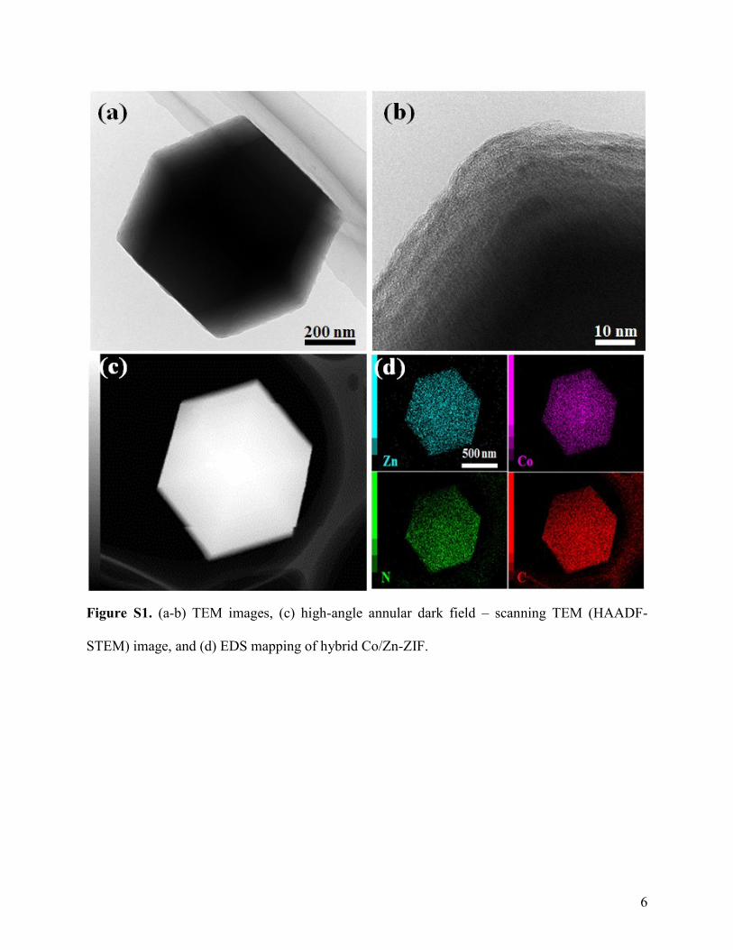
Figure S1. (a-b) TEM images, (c) high-angle annular dark field – scanning TEM (HAADF-
STEM) image, and (d) EDS mapping of hybrid Co/Zn-ZIF.

7
Figure S2. (a-c) SEM images of hybrid Co/Zn-ZIF-derived carbon.

8
Figure S3. High resolution TEM (HRTEM) image of hybrid Co/Zn-ZIF-derived carbon at edge
of particle. The Co nanoparticles are shown with the graphitic carbon structure.

9
Figure S4. (a) Nitrogen adsorption-desorption isotherms and pore size distributions for (b)
hybrid Co/Zn-ZIF and (c) hybrid Co/Zn-ZIF-derived carbon.

10
Figure S5. Wide-angle XRD patterns of (a) hybrid Co/Zn-ZIF and (b) hybrid Co/Zn-ZIF-derived
carbon. (c) Raman spectrum of hybrid Co/Zn-ZIF-derived carbon (intensity ratio for D and G
bands, ID/IG = 0.87).

11
Figure S6. (a) Galvanostatic charge-discharge curves, (b) specific capacitance of device at
different current densities, and (c) life cycle test of coin cells using organic electrolyte consisting
of 1.0 M tetrabutylammonium hexafluorophosphate (TBAPF6) in acetonitrile.