ingenico 9500 pci ped 1 - nets.eu · pdf filetype: title : integration guide i9500 pci ped 1.3...
TRANSCRIPT
Type: Title :
Integration Guide i9500 PCI PED 1.3
Page: Version: Date:
1 / 50 1.6.1
27/04/2010
Ingenico proprietary. All rights reserved.
INTEGRATION GUIDE
INGENICO 9500 PCI PED 1.3
Type: Title :
Integration Guide i9500 PCI PED 1.3
Page: Version: Date:
2 / 50 1.6.1
27/04/2010
i9500_Integration Guide_V1_6_1.doc Propriété INGENICO. Reproduction interdite.
The scope of this document is to assist 3rd party integrators when dealing with Ingenico product i9530 and i9550, certified PCI PED 1.3. It offers all information needed for a successful integration of i9500 products into unattended vending devices.
Updates table
Version Date Nature of modifications Author Visa 0.0 20/12/2007 First Draft S.Farràs
0.1 16/01/2008 Draft. General changes S.Farràs
0.2 23/01/2008 Draft. GPRS, Removal, Groundig & product life
S.Farràs
1.0 01/02/2008 First release S.Farràs J. Martinez
1.1 23/05/2008 Updates on : Bezel AFAS Removal alarm
S.Farràs J. Martinez
1.2 14/11/2008 Update drawings and text
P.Mogas
1.3 03/04/2009 Correct page 36 (length of stud), change to new logo
C.Melero P.Mogas
1.4 22/4/2009 Correct mistakes C.Melero P.Mogas
1.5 11/06/2009 Correct date in header P.Mogas 1.6 27/04/2010 PSTN suppression ; different
precisions and warnings on assembly procedure§3.2 ; Ingetrust Keys Warning
§1.6.5
F. Nguyen A. Soubirane
Type: Title :
Integration Guide i9500 PCI PED 1.3
Page: Version: Date:
3 / 50 1.6.1
27/04/2010
i9500_Integration Guide_V1_6_1.doc Propriété INGENICO. Reproduction interdite.
Table of contents
1 GENERAL ............................................ .................................................................5
1.1 Definition of acronyms............................. ........................................................5
1.2 Modularity......................................... .................................................................6 1.2.1 Diagram of i9500 connectivity and communications .....................................6 1.2.2 Example of integration ..................................................................................7
1.3 Description of modules............................. .......................................................8 1.3.1 i9530: Integrated PINpad with LCD module..................................................8 1.3.2 i9550: Manual hybrid card reader .................................................................9
1.4 Cables............................................. .................................................................10 1.4.1 Pinpad-to-reader link cable (RJ11 cable)....................................................10 1.4.2 Ethernet cable.............................................................................................10
1.5 Privacy Shield ..................................... ............................................................11
1.6 Optional components................................ .....................................................12 1.6.1 Power supply ..............................................................................................12 1.6.2 PC linking cable ..........................................................................................13 1.6.3 Powered cable ............................................................................................14 1.6.4 Powered loading cable ...............................................................................15 1.6.5 Certificate injection cable ............................................................................17 1.6.6 Frontplate adaptor ......................................................................................18
2 POWERING, INTERCONNECTION AND FITTING THE SAM AND M MC DEVICES...................................................................................................................21
2.1 Powering the units................................. .........................................................21
2.2 Connectivity ....................................... .............................................................22 2.2.1 Interconnectivity between the PIN PAD and the SCR.................................22 2.2.2 PIN PAD connection ports ..........................................................................22 2.2.3 ETHERNET ................................................................................................23 2.2.4 GPRS..........................................................................................................24
2.3 Installation of the SAMs AND MMC................... ............................................26
3 ASSEMBLY........................................... ..............................................................27
3.1 General installation recommendations............... ..........................................27

Type: Title :
Integration Guide i9500 PCI PED 1.3
Page: Version: Date:
4 / 50 1.6.1
27/04/2010
i9500_Integration Guide_V1_6_1.doc Propriété INGENICO. Reproduction interdite.
3.2 Assembly procedure for i9550 manual hybrid card rea der.........................28 3.2.1 Kiosk/ UPT Preparation ..............................................................................28 3.2.2 Installing the Reader i9550 .........................................................................30 3.2.3 Kiosk design constraint – water ingress......................................................35
3.3 Assembly procedure for i9530 Integrated PINpad ..... ..................................36 3.3.1 Kiosk/ UPT Preparation ..............................................................................36 3.3.2 Installation of the privacy shield ..................................................................37 3.3.3 Installation of the i9530 PIN-pad.................................................................39
4 TECHNICAL AND ENVIRONMENTAL SPECIFICATIONS ......... .......................42
4.1 Electrical consumptions ............................ ....................................................42
4.2 Temperature and humidity........................... ..................................................42
4.3 Environmental specification continued.............. ..........................................42
4.4 Operating life..................................... ..............................................................43
5 CLEANING INSTRUCTIONS .............................. ................................................44
6 CERTIFICATIONS...............................................................................................45
7 RESPONSIBILITY LIMITS .............................. ....................................................46
7.1 Responsibilities ................................... ...........................................................46
7.2 Security certifications and approvals .............. .............................................46 7.2.1 Validity of the security approvals ................................................................46 7.2.2 Privacy shield..............................................................................................46
8 REMOVAL DETECTION ALARM SCREEN SHOTS............... ...........................47
9 APPENDIX ..........................................................................................................50
9.1 Gasket used for i9550.............................. .......................................................50 9.1.1 DIV304252A drawing..................................................................................50
Type: Title :
Integration Guide i9500 PCI PED 1.3
Page: Version: Date:
5 / 50 1.6.1
27/04/2010
i9500_Integration Guide_V1_6_1.doc Propriété INGENICO. Reproduction interdite.
1 GENERAL
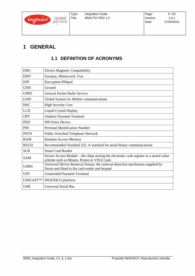
1.1 DEFINITION OF ACRONYMS EMC Electro Magnetic Compatibility
EMV Europay, Mastercard, Visa
EPP Encryption PINpad
GND Ground
GPRS General Packet Radio Service
GSM Global System for Mobile communications
HSC High Security Core
LCD Liquid Crystal Display
OPT Outdoor Payment Terminal
PED PIN Entry Device
PIN Personal Identification Number
PSTN Public Switched Telephone Network
RAM Random Access Memory
RS232 Recommended Standard 232. A standard for serial binary communications
SCR Smart Card Reader
SAM Secure Access Module – the chips storing the electronic cash register in a stored value scheme such as Moneo, Proton or VISA Cash.
UDRS Universal Device Removal Sensor, the removal detection mechanism supplied by Storm and fitted to the card reader and keypad
UPT Unattended Payment Terminal
UNICAPT™ INGENICO platform
USB Universal Serial Bus
Type: Title :
Integration Guide i9500 PCI PED 1.3
Page: Version: Date:
6 / 50 1.6.1
27/04/2010
i9500_Integration Guide_V1_6_1.doc Propriété INGENICO. Reproduction interdite.
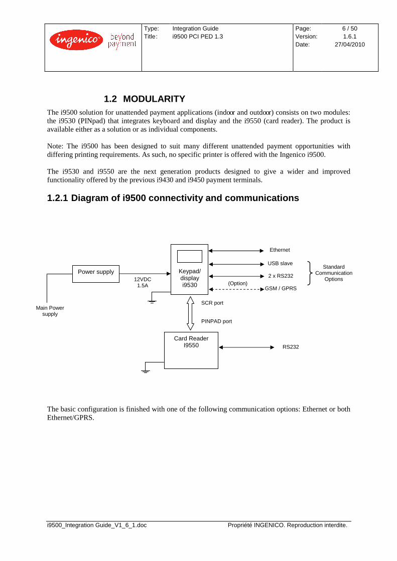
1.2 MODULARITY The i9500 solution for unattended payment applications (indoor and outdoor) consists on two modules: the i9530 (PINpad) that integrates keyboard and display and the i9550 (card reader). The product is available either as a solution or as individual components. Note: The i9500 has been designed to suit many different unattended payment opportunities with differing printing requirements. As such, no specific printer is offered with the Ingenico i9500. The i9530 and i9550 are the next generation products designed to give a wider and improved functionality offered by the previous i9430 and i9450 payment terminals.
1.2.1 Diagram of i9500 connectivity and communicati ons
The basic configuration is finished with one of the following communication options: Ethernet or both Ethernet/GPRS.
Keypad/ display i9530
Card Reader I9550
Power supply
Main Power supply
Ethernet
USB slave
2 x RS232
GSM / GPRS (Option)
Standard Communication
Options 12VDC 1.5A
RS232
SCR port PINPAD port
Type: Title :
Integration Guide i9500 PCI PED 1.3
Page: Version: Date:
7 / 50 1.6.1
27/04/2010
i9500_Integration Guide_V1_6_1.doc Propriété INGENICO. Reproduction interdite.
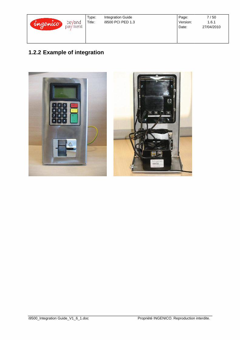
1.2.2 Example of integration
Type: Title :
Integration Guide i9500 PCI PED 1.3
Page: Version: Date:
8 / 50 1.6.1
27/04/2010
i9500_Integration Guide_V1_6_1.doc Propriété INGENICO. Reproduction interdite.
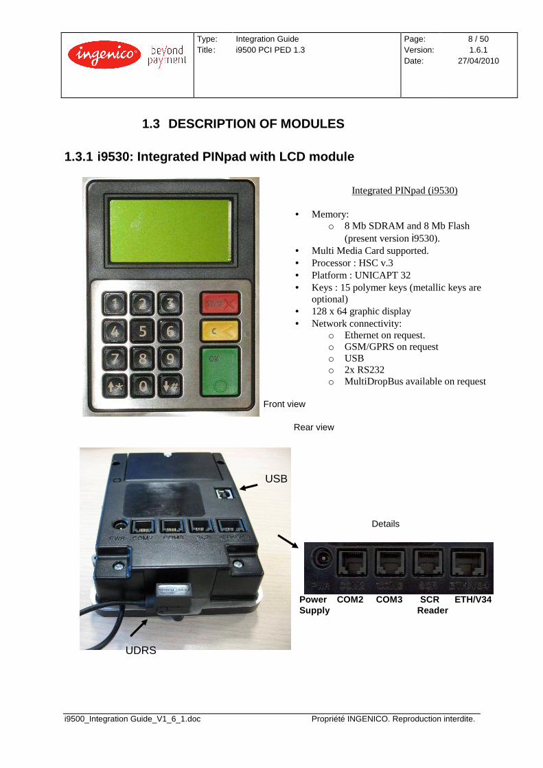
1.3 DESCRIPTION OF MODULES 1.3.1 i9530: Integrated PINpad with LCD module
Front view
Rear view
Details
UDRS
USB
Power COM2 COM3 SCR ETH/V34 Supply Reader
Integrated PINpad (i9530)
• Memory: o 8 Mb SDRAM and 8 Mb Flash
(present version i9530). • Multi Media Card supported. • Processor : HSC v.3 • Platform : UNICAPT 32 • Keys : 15 polymer keys (metallic keys are
optional) • 128 x 64 graphic display • Network connectivity:
o Ethernet on request. o GSM/GPRS on request o USB o 2x RS232 o MultiDropBus available on request
Type: Title :
Integration Guide i9500 PCI PED 1.3
Page: Version: Date:
9 / 50 1.6.1
27/04/2010
i9500_Integration Guide_V1_6_1.doc Propriété INGENICO. Reproduction interdite.
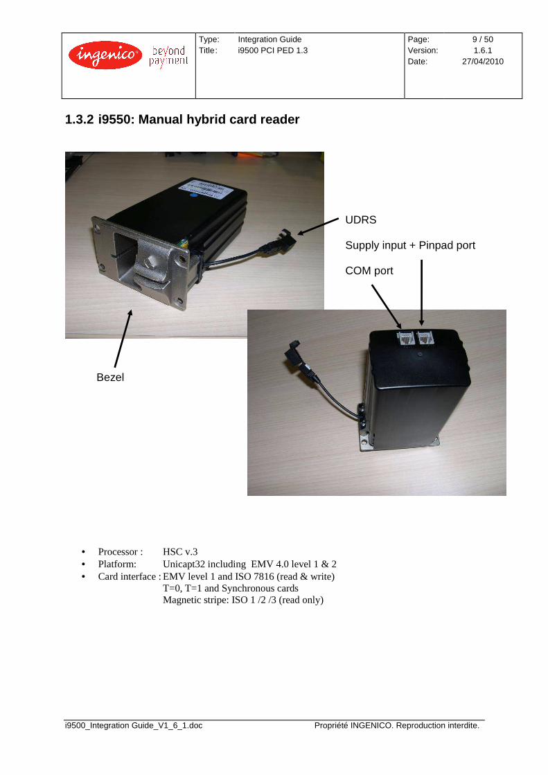
1.3.2 i9550: Manual hybrid card reader
• Processor : HSC v.3 • Platform: Unicapt32 including EMV 4.0 level 1 & 2 • Card interface : EMV level 1 and ISO 7816 (read & write)
T=0, T=1 and Synchronous cards Magnetic stripe: ISO 1 /2 /3 (read only)
UDRS Supply input + Pinpad port COM port
Bezel

Type: Title :
Integration Guide i9500 PCI PED 1.3
Page: Version: Date:
10 / 50 1.6.1
27/04/2010
i9500_Integration Guide_V1_6_1.doc Propriété INGENICO. Reproduction interdite.
1.4 CABLES 1.4.1 Pinpad-to-reader link cable (RJ11 cable) The interconnection between the i9530 and the i9550 is provided by an RS232 communication cable CAB425301A. This cable is provided with the i9550.
Pin out for the link cable CAB425301A is shown below:
1.4.2 Ethernet cable To connect the i9530 to the Ethernet network, an Ethernet cable is required. A standard Ethernet cable can be used for this connection.
Type: Title :
Integration Guide i9500 PCI PED 1.3
Page: Version: Date:
11 / 50 1.6.1
27/04/2010
i9500_Integration Guide_V1_6_1.doc Propriété INGENICO. Reproduction interdite.
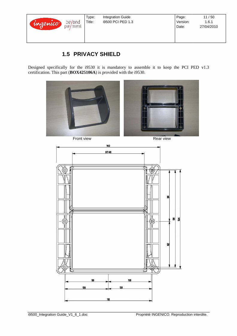
1.5 PRIVACY SHIELD Designed specifically for the i9530 it is mandatory to assemble it to keep the PCI PED v1.3 certification. This part (BOX425106A) is provided with the i9530.
Front view Rear view

Type: Title :
Integration Guide i9500 PCI PED 1.3
Page: Version: Date:
12 / 50 1.6.1
27/04/2010
i9500_Integration Guide_V1_6_1.doc Propriété INGENICO. Reproduction interdite.
1.6 OPTIONAL COMPONENTS
1.6.1 Power supply The Ingenico reference for the European power supply is ALI0091.
• Input: Mains voltage supply ranging from 100V to 240V • Maximum current of 0.8A • Working frequency range between 47Hz and 63Hz • Output: Regulated DC voltage 12V – 2.6A

Type: Title :
Integration Guide i9500 PCI PED 1.3
Page: Version: Date:
13 / 50 1.6.1
27/04/2010
i9500_Integration Guide_V1_6_1.doc Propriété INGENICO. Reproduction interdite.
1.6.2 PC linking cable This cable (CAB325303A) is used for the interconnection between PIN-pad or Reader and PC through a RS232 serial port.
Type: Title :
Integration Guide i9500 PCI PED 1.3
Page: Version: Date:
14 / 50 1.6.1
27/04/2010
i9500_Integration Guide_V1_6_1.doc Propriété INGENICO. Reproduction interdite.
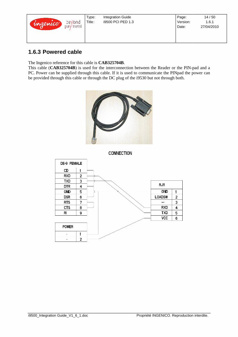
1.6.3 Powered cable The Ingenico reference for this cable is CAB325704B. This cable (CAB325704B) is used for the interconnection between the Reader or the PIN-pad and a PC. Power can be supplied through this cable. If it is used to communicate the PINpad the power can be provided through this cable or through the DC plug of the i9530 but not through both.
Type: Title :
Integration Guide i9500 PCI PED 1.3
Page: Version: Date:
15 / 50 1.6.1
27/04/2010
i9500_Integration Guide_V1_6_1.doc Propriété INGENICO. Reproduction interdite.
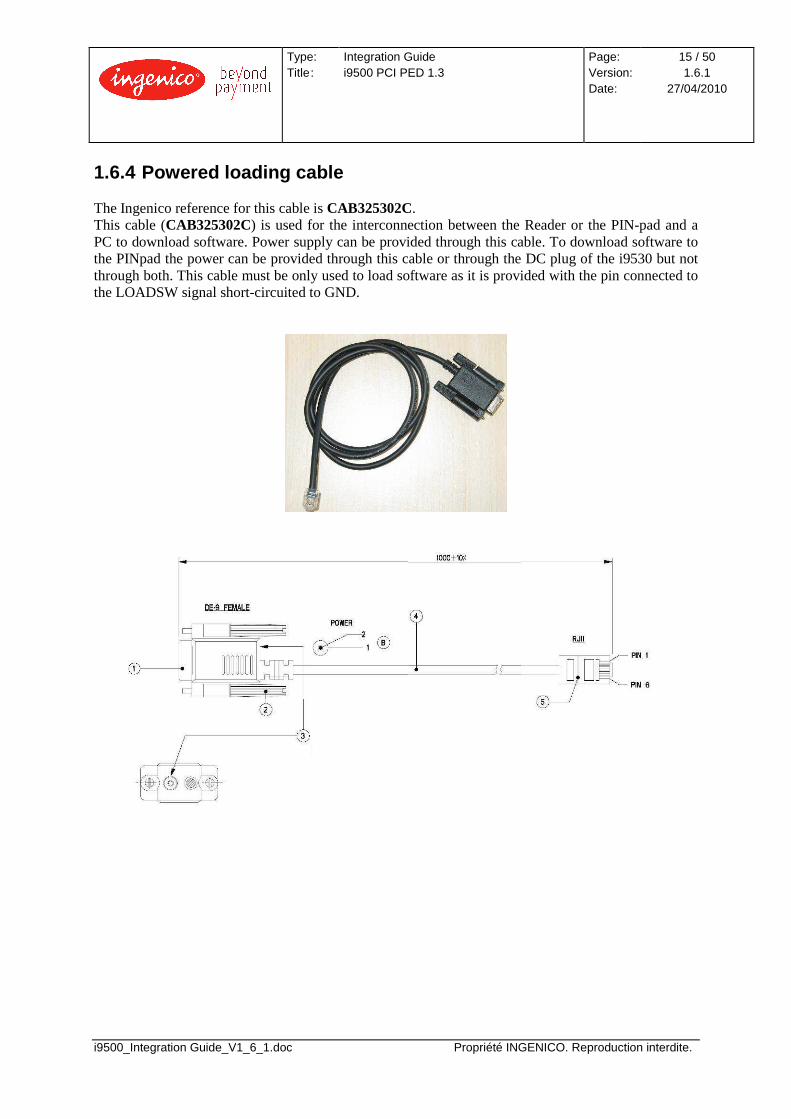
1.6.4 Powered loading cable The Ingenico reference for this cable is CAB325302C. This cable (CAB325302C) is used for the interconnection between the Reader or the PIN-pad and a PC to download software. Power supply can be provided through this cable. To download software to the PINpad the power can be provided through this cable or through the DC plug of the i9530 but not through both. This cable must be only used to load software as it is provided with the pin connected to the LOADSW signal short-circuited to GND.
Type: Title :
Integration Guide i9500 PCI PED 1.3
Page: Version: Date:
16 / 50 1.6.1
27/04/2010
i9500_Integration Guide_V1_6_1.doc Propriété INGENICO. Reproduction interdite.
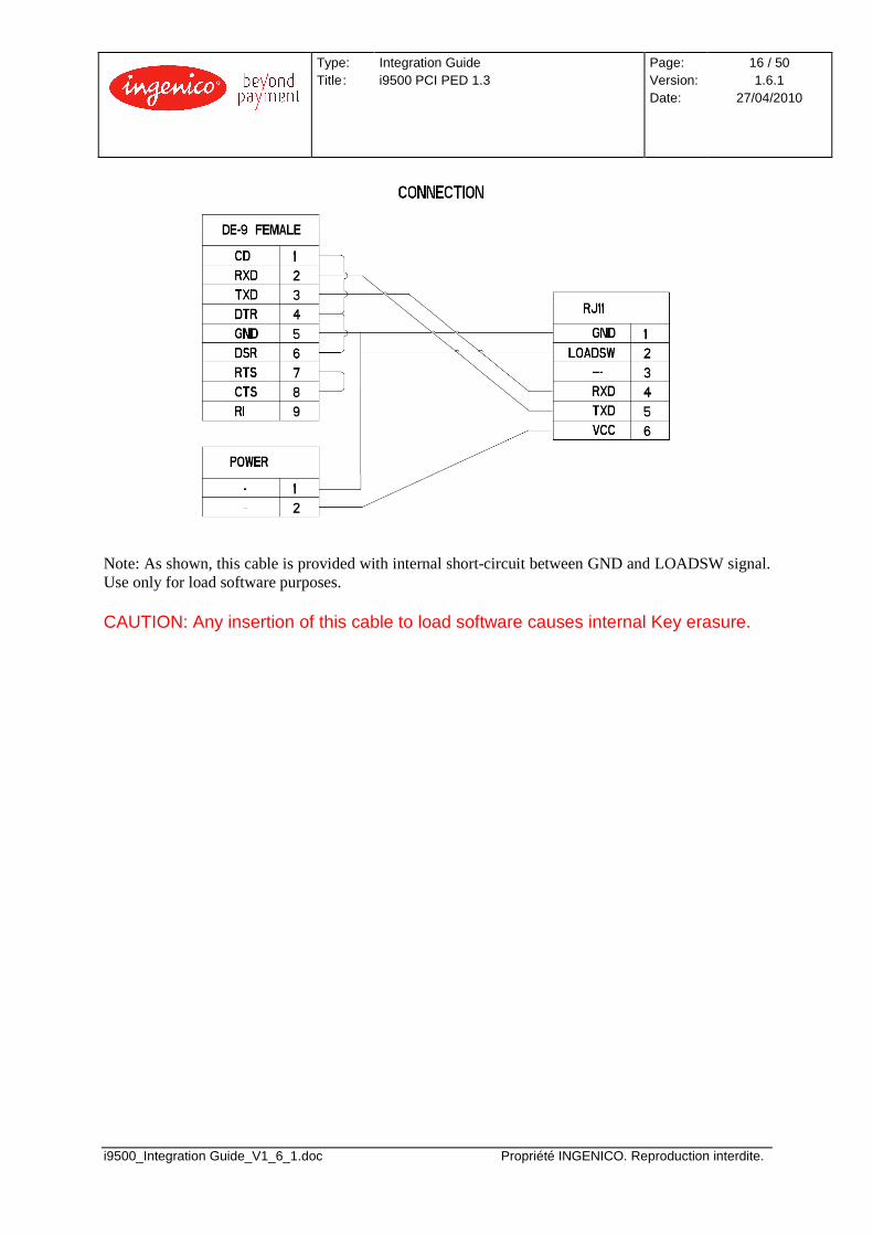
Note: As shown, this cable is provided with internal short-circuit between GND and LOADSW signal. Use only for load software purposes. CAUTION: Any insertion of this cable to load software causes internal Key erasure.
Type: Title :
Integration Guide i9500 PCI PED 1.3
Page: Version: Date:
17 / 50 1.6.1
27/04/2010
i9500_Integration Guide_V1_6_1.doc Propriété INGENICO. Reproduction interdite.
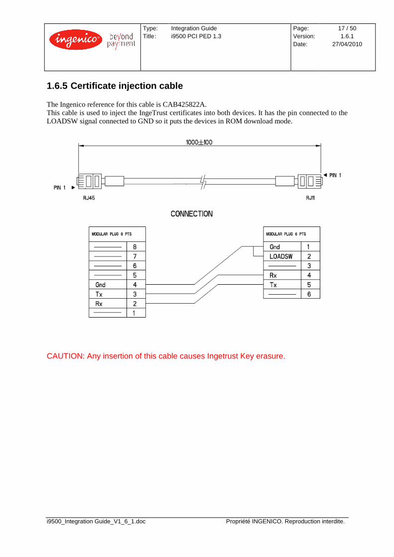
1.6.5 Certificate injection cable The Ingenico reference for this cable is CAB425822A. This cable is used to inject the IngeTrust certificates into both devices. It has the pin connected to the LOADSW signal connected to GND so it puts the devices in ROM download mode.
CAUTION: Any insertion of this cable causes Ingetrust Key erasure.
Type: Title :
Integration Guide i9500 PCI PED 1.3
Page: Version: Date:
18 / 50 1.6.1
27/04/2010
i9500_Integration Guide_V1_6_1.doc Propriété INGENICO. Reproduction interdite.
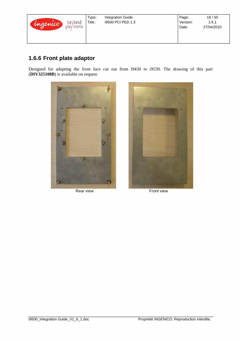
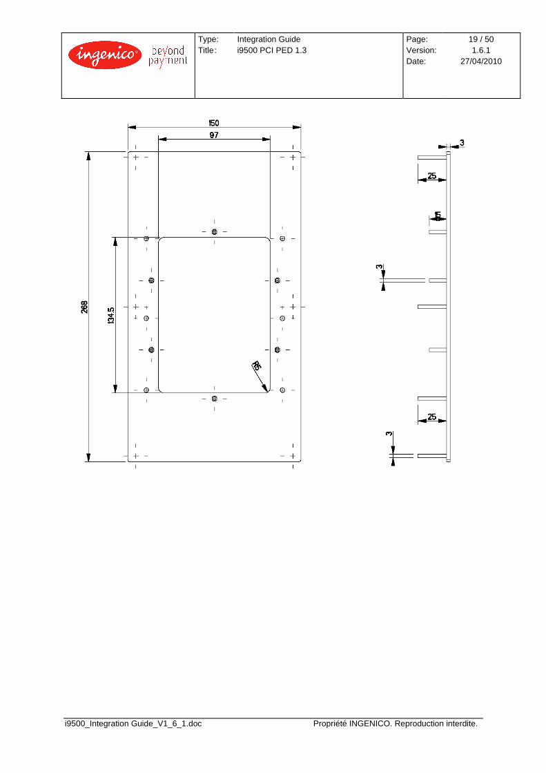
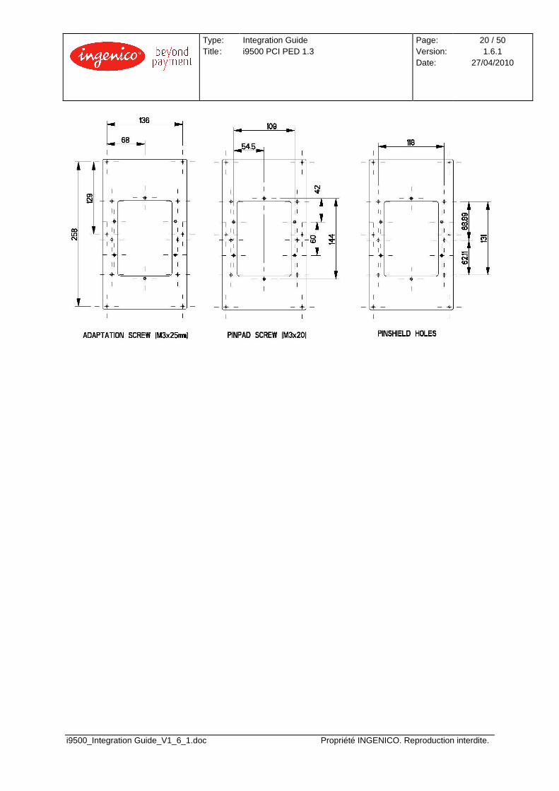
1.6.6 Front plate adaptor Designed for adapting the front face cut out from i9430 to i9530. The drawing of this part (DIV325108B) is available on request.
Rear view Front view
Type: Title :
Integration Guide i9500 PCI PED 1.3
Page: Version: Date:
19 / 50 1.6.1
27/04/2010
i9500_Integration Guide_V1_6_1.doc Propriété INGENICO. Reproduction interdite.
Type: Title :
Integration Guide i9500 PCI PED 1.3
Page: Version: Date:
20 / 50 1.6.1
27/04/2010
i9500_Integration Guide_V1_6_1.doc Propriété INGENICO. Reproduction interdite.
Type: Title :
Integration Guide i9500 PCI PED 1.3
Page: Version: Date:
21 / 50 1.6.1
27/04/2010
i9500_Integration Guide_V1_6_1.doc Propriété INGENICO. Reproduction interdite.
2 POWERING, INTERCONNECTION AND FITTING THE SAM AND MMC DEVICES
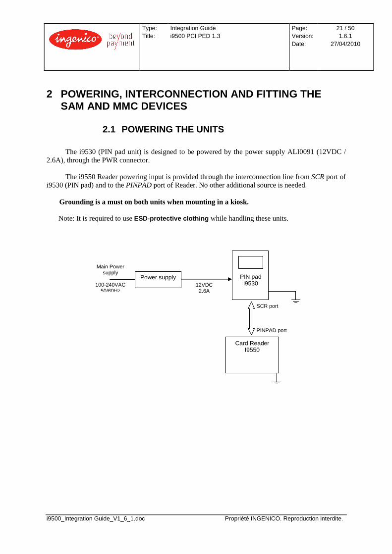
2.1 POWERING THE UNITS
The i9530 (PIN pad unit) is designed to be powered by the power supply ALI0091 (12VDC / 2.6A), through the PWR connector.
The i9550 Reader powering input is provided through the interconnection line from SCR port of
i9530 (PIN pad) and to the PINPAD port of Reader. No other additional source is needed. Grounding is a must on both units when mounting in a kiosk.
Note: It is required to use ESD-protective clothing while handling these units.
PIN pad i9530
Card Reader I9550
Power supply
Main Power supply
100-240VAC
50/60Hz 12VDC
2.6A
SCR port PINPAD port
Type: Title :
Integration Guide i9500 PCI PED 1.3
Page: Version: Date:
22 / 50 1.6.1
27/04/2010
i9500_Integration Guide_V1_6_1.doc Propriété INGENICO. Reproduction interdite.
2.2 CONNECTIVITY
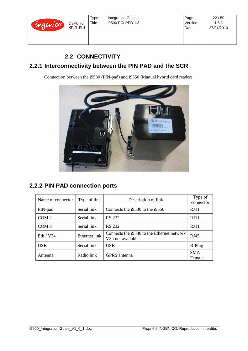
2.2.1 Interconnectivity between the PIN PAD and the SCR
Connection between the i9530 (PIN-pad) and i9550 (Manual hybrid card reader)
2.2.2 PIN PAD connection ports
Name of connector Type of link Description of link Type of
connector
PIN-pad Serial link Connects the i9530 to the i9550 RJ11
COM 2 Serial link RS 232 RJ11
COM 3 Serial link RS 232 RJ11
Eth / V34 Ethernet link Connects the i9530 to the Ethernet network V34 not available
RJ45
USB Serial link USB B-Plug
Antenna Radio link GPRS antenna SMA Female
Type: Title :
Integration Guide i9500 PCI PED 1.3
Page: Version: Date:
23 / 50 1.6.1
27/04/2010
i9500_Integration Guide_V1_6_1.doc Propriété INGENICO. Reproduction interdite.
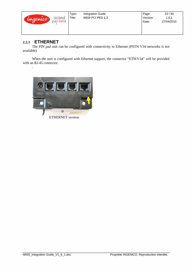
2.2.3 ETHERNET The PIN pad unit can be configured with connectivity to Ethernet (PSTN V34 networks is not
available) When the unit is configured with Ethernet support, the connector “ETH/V34” will be provided
with an RJ-45 connector. .
ETHERNET version
Type: Title :
Integration Guide i9500 PCI PED 1.3
Page: Version: Date:
24 / 50 1.6.1
27/04/2010
i9500_Integration Guide_V1_6_1.doc Propriété INGENICO. Reproduction interdite.
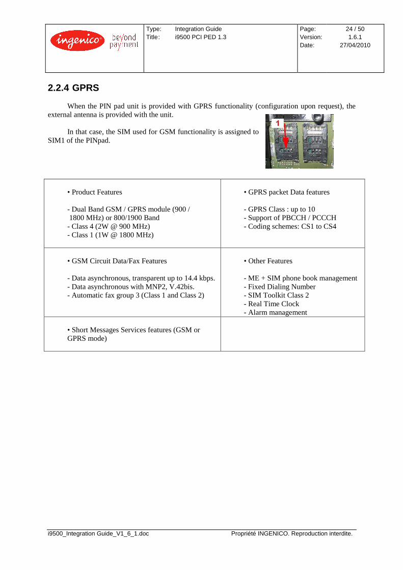
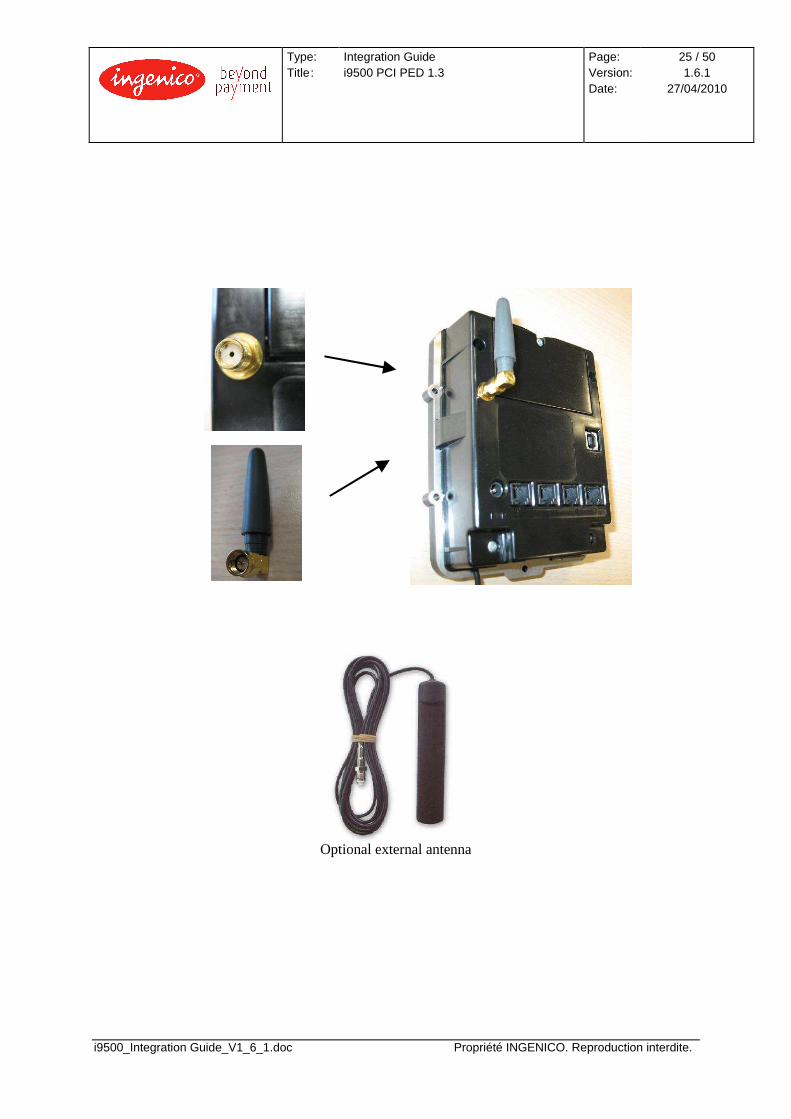
2.2.4 GPRS
When the PIN pad unit is provided with GPRS functionality (configuration upon request), the external antenna is provided with the unit.
In that case, the SIM used for GSM functionality is assigned to
SIM1 of the PINpad.
• Product Features - Dual Band GSM / GPRS module (900 / 1800 MHz) or 800/1900 Band - Class 4 (2W @ 900 MHz) - Class 1 (1W @ 1800 MHz)
• GPRS packet Data features - GPRS Class : up to 10 - Support of PBCCH / PCCCH - Coding schemes: CS1 to CS4
• GSM Circuit Data/Fax Features - Data asynchronous, transparent up to 14.4 kbps. - Data asynchronous with MNP2, V.42bis. - Automatic fax group 3 (Class 1 and Class 2)
• Other Features - ME + SIM phone book management - Fixed Dialing Number - SIM Toolkit Class 2 - Real Time Clock - Alarm management
• Short Messages Services features (GSM or GPRS mode)
Type: Title :
Integration Guide i9500 PCI PED 1.3
Page: Version: Date:
25 / 50 1.6.1
27/04/2010
i9500_Integration Guide_V1_6_1.doc Propriété INGENICO. Reproduction interdite.
Optional external antenna
Type: Title :
Integration Guide i9500 PCI PED 1.3
Page: Version: Date:
26 / 50 1.6.1
27/04/2010
i9500_Integration Guide_V1_6_1.doc Propriété INGENICO. Reproduction interdite.
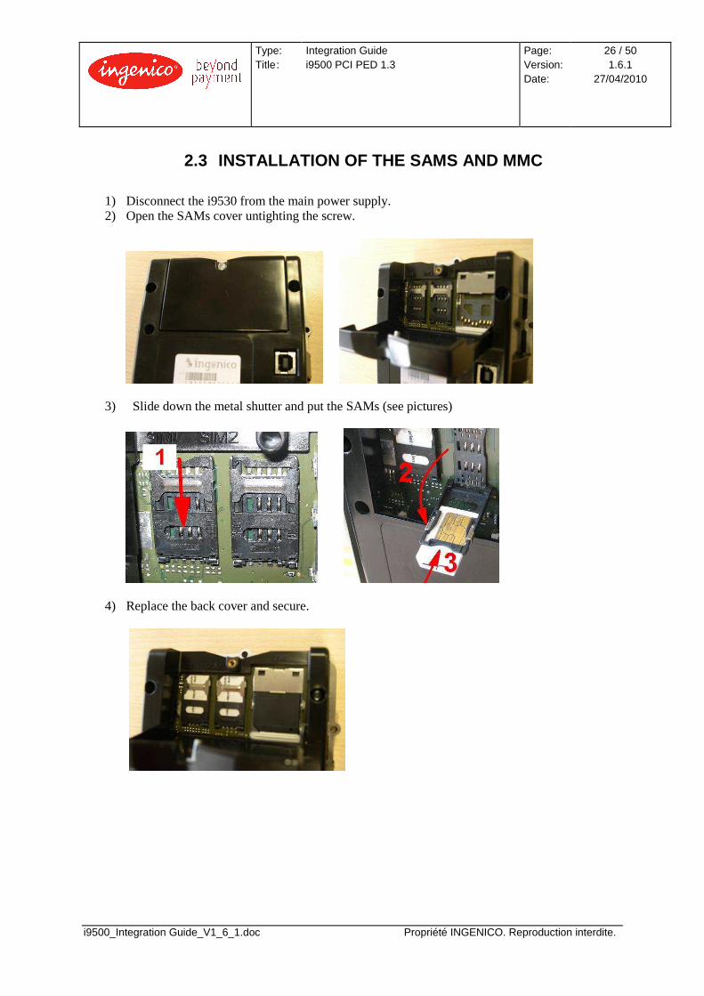
2.3 INSTALLATION OF THE SAMS AND MMC
1) Disconnect the i9530 from the main power supply. 2) Open the SAMs cover untighting the screw.
3) Slide down the metal shutter and put the SAMs (see pictures)
4) Replace the back cover and secure.

Type: Title :
Integration Guide i9500 PCI PED 1.3
Page: Version: Date:
27 / 50 1.6.1
27/04/2010
i9500_Integration Guide_V1_6_1.doc Propriété INGENICO. Reproduction interdite.
3 ASSEMBLY
Note: It is required the use of ESD-protective clothing while handling these devices.
3.1 GENERAL INSTALLATION RECOMMENDATIONS
1) Ensure that you have enough free space for installation, operational and maintenance needs. 2) Be aware of the safety regulations. 3) Carefully consider the general and local payment security requirements and any impact they
may have on the kiosk 4) Carefully consider the ergonomic aspects and also the local acts or recommendations
concerning disabled and visually impaired people. 5) See environmental specification and especially in case of very cold weather, take steps to
ensure that the internal temperature is at least -5 °C.
Type: Title :
Integration Guide i9500 PCI PED 1.3
Page: Version: Date:
28 / 50 1.6.1
27/04/2010
i9500_Integration Guide_V1_6_1.doc Propriété INGENICO. Reproduction interdite.
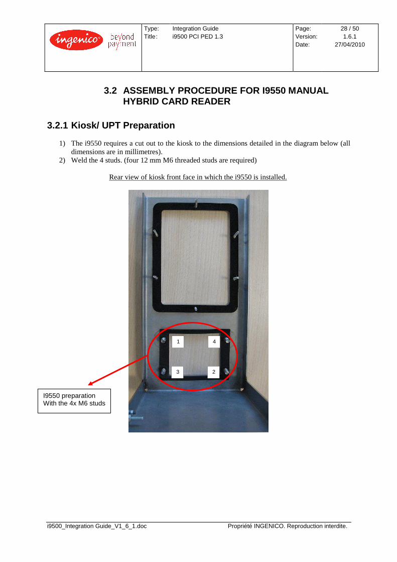
3.2 ASSEMBLY PROCEDURE FOR I9550 MANUAL HYBRID CARD READER
3.2.1 Kiosk/ UPT Preparation
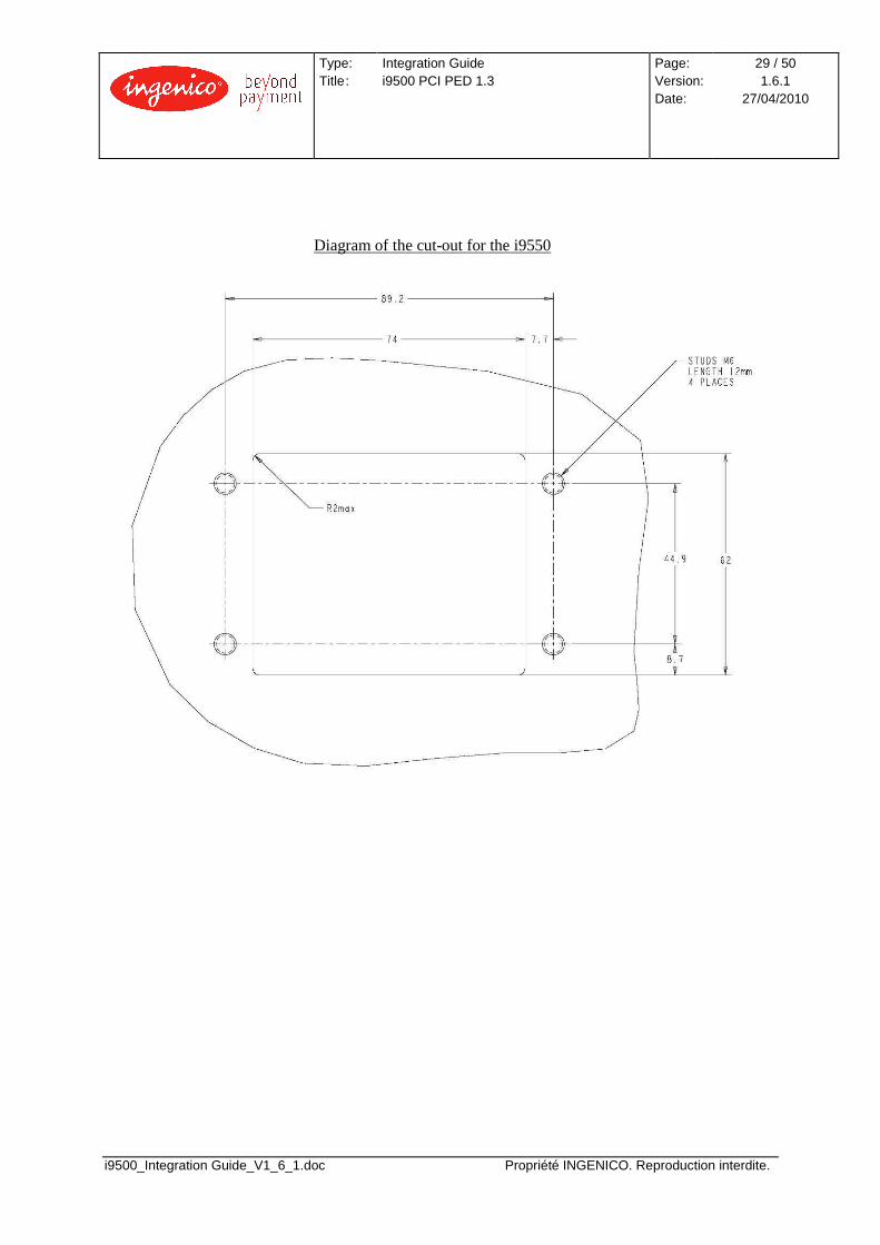
1) The i9550 requires a cut out to the kiosk to the dimensions detailed in the diagram below (all dimensions are in millimetres).
2) Weld the 4 studs. (four 12 mm M6 threaded studs are required)
Rear view of kiosk front face in which the i9550 is installed.
1
3
4
2
I9550 preparation With the 4x M6 studs
Type: Title :
Integration Guide i9500 PCI PED 1.3
Page: Version: Date:
29 / 50 1.6.1
27/04/2010
i9500_Integration Guide_V1_6_1.doc Propriété INGENICO. Reproduction interdite.
Diagram of the cut-out for the i9550

Type: Title :
Integration Guide i9500 PCI PED 1.3
Page: Version: Date:
30 / 50 1.6.1
27/04/2010
i9500_Integration Guide_V1_6_1.doc Propriété INGENICO. Reproduction interdite.
3.2.2 Installing the Reader i9550 The i9550 includes a security removal sensor (UDRS) that should be handled carefully during the installation procedure to ensure reliable operation in the field. A M6/M3 adaptor (see pictures) is supplied and should be used to allow the UDRS to be connected to the M6 stud.
M3/M6 adaptor Outer sleeve Slotted spacer
Type: Title :
Integration Guide i9500 PCI PED 1.3
Page: Version: Date:
31 / 50 1.6.1
27/04/2010
i9500_Integration Guide_V1_6_1.doc Propriété INGENICO. Reproduction interdite.
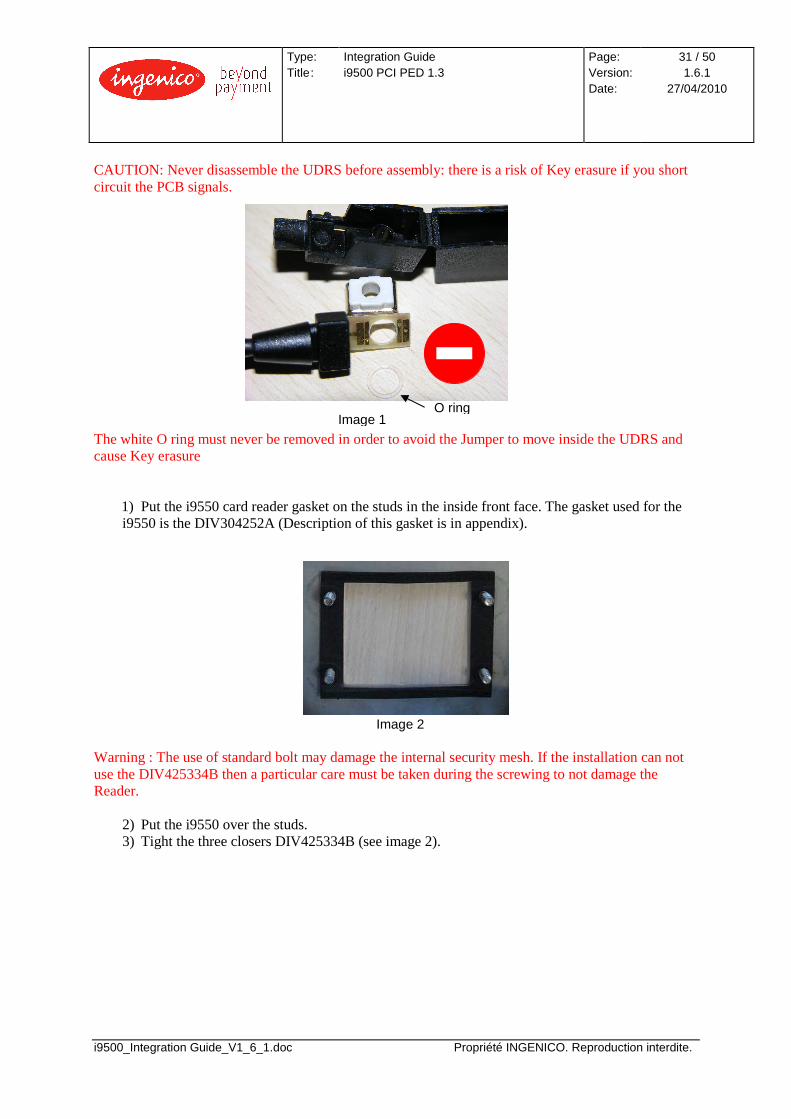
CAUTION: Never disassemble the UDRS before assembly: there is a risk of Key erasure if you short circuit the PCB signals. The white O ring must never be removed in order to avoid the Jumper to move inside the UDRS and cause Key erasure
1) Put the i9550 card reader gasket on the studs in the inside front face. The gasket used for the i9550 is the DIV304252A (Description of this gasket is in appendix).
Image 2 Warning : The use of standard bolt may damage the internal security mesh. If the installation can not use the DIV425334B then a particular care must be taken during the screwing to not damage the Reader.
2) Put the i9550 over the studs. 3) Tight the three closers DIV425334B (see image 2).
Image 1 O ring
Type: Title :
Integration Guide i9500 PCI PED 1.3
Page: Version: Date:
32 / 50 1.6.1
27/04/2010
i9500_Integration Guide_V1_6_1.doc Propriété INGENICO. Reproduction interdite.
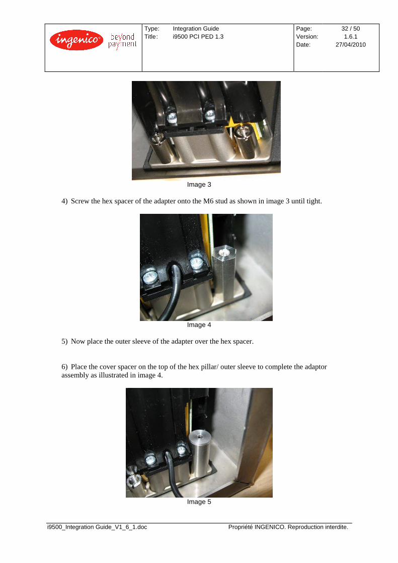
Image 3
4) Screw the hex spacer of the adapter onto the M6 stud as shown in image 3 until tight.
Image 4
5) Now place the outer sleeve of the adapter over the hex spacer.
6) Place the cover spacer on the top of the hex pillar/ outer sleeve to complete the adaptor assembly as illustrated in image 4.
Image 5
Type: Title :
Integration Guide i9500 PCI PED 1.3
Page: Version: Date:
33 / 50 1.6.1
27/04/2010
i9500_Integration Guide_V1_6_1.doc Propriété INGENICO. Reproduction interdite.
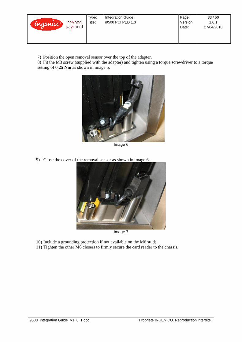
7) Position the open removal sensor over the top of the adapter. 8) Fit the M3 screw (supplied with the adapter) and tighten using a torque screwdriver to a torque setting of 0,25 Nm as shown in image 5.
Image 6
9) Close the cover of the removal sensor as shown in image 6.
Image 7
10) Include a grounding protection if not available on the M6 studs. 11) Tighten the other M6 closers to firmly secure the card reader to the chassis.

Type: Title :
Integration Guide i9500 PCI PED 1.3
Page: Version: Date:
34 / 50 1.6.1
27/04/2010
i9500_Integration Guide_V1_6_1.doc Propriété INGENICO. Reproduction interdite.
Dimensions of the i9550

Type: Title :
Integration Guide i9500 PCI PED 1.3
Page: Version: Date:
35 / 50 1.6.1
27/04/2010
i9500_Integration Guide_V1_6_1.doc Propriété INGENICO. Reproduction interdite.
3.2.3 Kiosk design constraint – water ingress The i9550 card reader has an IP rating of x4. This means that the device is protected against liquid sprays from all directions - limited ingress permitted. Water ingress is possible due to the card slot. As a result the card reader should not be positioned directly above sensitive electrical equipment if water ingress is a possibility. IP testing of the card reader has demonstrated that small amounts of water do enter the device but do not affect the performance of the card reader. The small amounts of water drain through the slots in the mechanical housing. Therefore card reader positioning and drainage slots located below the card reader should be considered in external positions.
Type: Title :
Integration Guide i9500 PCI PED 1.3
Page: Version: Date:
36 / 50 1.6.1
27/04/2010
i9500_Integration Guide_V1_6_1.doc Propriété INGENICO. Reproduction interdite.
3.3 ASSEMBLY PROCEDURE FOR I9530 INTEGRATED PINPAD
3.3.1 Kiosk/ UPT Preparation
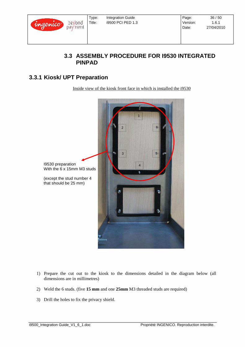
Inside view of the kiosk front face in which is installed the i9530
I9530 preparation With the 6 x 15mm M3 studs
(except the stud number 4 that should be 25 mm)
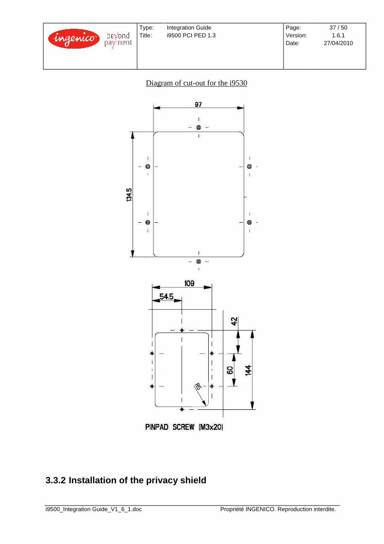
1) Prepare the cut out to the kiosk to the dimensions detailed in the diagram below (all dimensions are in millimetres)
2) Weld the 6 studs. (five 15 mm and one 25mm M3 threaded studs are required)
3) Drill the holes to fix the privacy shield.
1
2
3
4
5
6
Type: Title :
Integration Guide i9500 PCI PED 1.3
Page: Version: Date:
37 / 50 1.6.1
27/04/2010
i9500_Integration Guide_V1_6_1.doc Propriété INGENICO. Reproduction interdite.
Diagram of cut-out for the i9530
3.3.2 Installation of the privacy shield

Type: Title :
Integration Guide i9500 PCI PED 1.3
Page: Version: Date:
38 / 50 1.6.1
27/04/2010
i9500_Integration Guide_V1_6_1.doc Propriété INGENICO. Reproduction interdite.
Important: The privacy shield must be installed before the i9530 Integrated PINpad
1) First, position the privacy shield in the desired orientation and position on the outside face of the kiosk.
2) Now using six M3x12 screws insert the mounting screws from inside the kiosk chassis and screw into the threaded inserts of the privacy shield to secure the privacy shield to the chassis.
Privacy shield cut-out:
Remark: in case of the i9530 is installed without the shield, remove the i9530, remove the gasket, drill the holes and install the privacy shield. Afterwards, follow the mounting instructions.
Type: Title :
Integration Guide i9500 PCI PED 1.3
Page: Version: Date:
39 / 50 1.6.1
27/04/2010
i9500_Integration Guide_V1_6_1.doc Propriété INGENICO. Reproduction interdite.
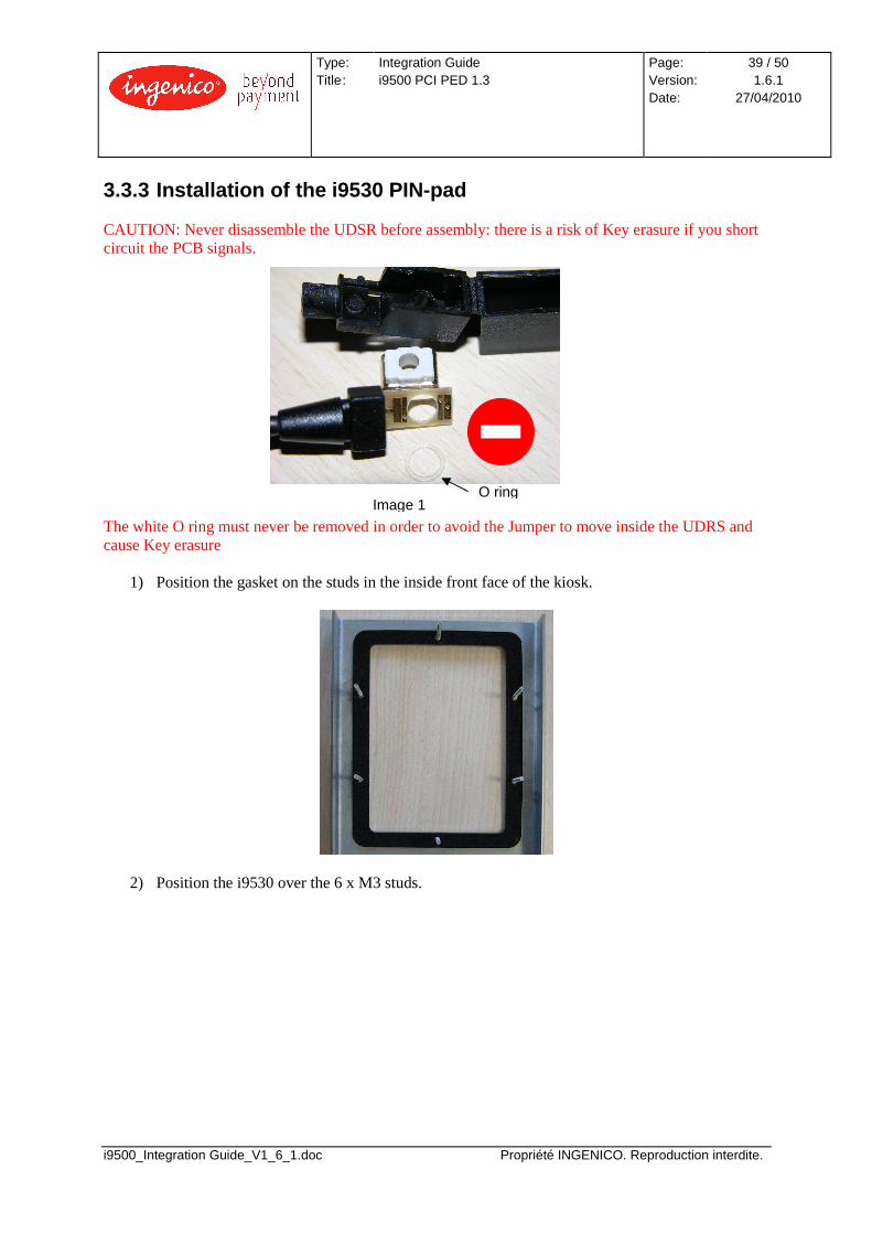
3.3.3 Installation of the i9530 PIN-pad CAUTION: Never disassemble the UDSR before assembly: there is a risk of Key erasure if you short circuit the PCB signals. The white O ring must never be removed in order to avoid the Jumper to move inside the UDRS and cause Key erasure
1) Position the gasket on the studs in the inside front face of the kiosk.
2) Position the i9530 over the 6 x M3 studs.
Image 1 O ring
Type: Title :
Integration Guide i9500 PCI PED 1.3
Page: Version: Date:
40 / 50 1.6.1
27/04/2010
i9500_Integration Guide_V1_6_1.doc Propriété INGENICO. Reproduction interdite.
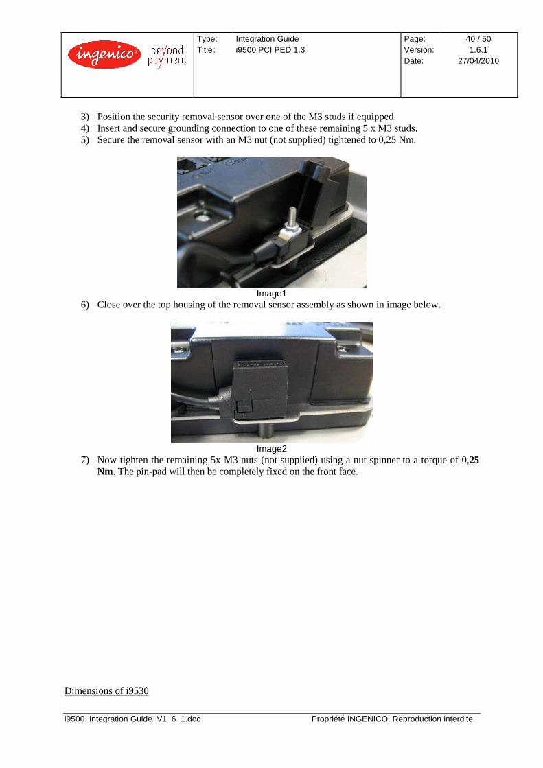
3) Position the security removal sensor over one of the M3 studs if equipped. 4) Insert and secure grounding connection to one of these remaining 5 x M3 studs. 5) Secure the removal sensor with an M3 nut (not supplied) tightened to 0,25 Nm.
Image1
6) Close over the top housing of the removal sensor assembly as shown in image below.
Image2
7) Now tighten the remaining 5x M3 nuts (not supplied) using a nut spinner to a torque of 0,25 Nm. The pin-pad will then be completely fixed on the front face.
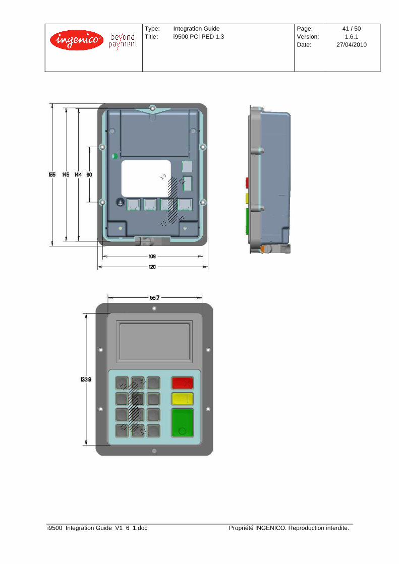
Dimensions of i9530
Type: Title :
Integration Guide i9500 PCI PED 1.3
Page: Version: Date:
41 / 50 1.6.1
27/04/2010
i9500_Integration Guide_V1_6_1.doc Propriété INGENICO. Reproduction interdite.

Type: Title :
Integration Guide i9500 PCI PED 1.3
Page: Version: Date:
42 / 50 1.6.1
27/04/2010
i9500_Integration Guide_V1_6_1.doc Propriété INGENICO. Reproduction interdite.
4 TECHNICAL AND ENVIRONMENTAL SPECIFICATIONS
4.1 ELECTRICAL CONSUMPTIONS • Average consumptions:
o I9530 – Pin-pad < 300 mA o I9550 – Reader < 150 mA
• Maximum average external supply current: o I9530 – Pin-pad < 1A o I9550 – Reader < 0,5 A
• Maximum consumption in stand by mode: o I9530 – Pin-pad < 75 mA (Ethernet configuration) o I9550 – Reader < 15 mA
Note: All these values measured at 12 VDC input.
4.2 TEMPERATURE AND HUMIDITY Operating conditions (i9530 and i9550):
• Relative humidity: 5% - 95%. No condensing. • External temperature range: -25 °C to 65 °C. • Internal temperature: minimum -5 °C
Storage conditions (i9530 and i9550):
• Relative humidity: 5% - 95%. No condensing. • External temperature range: -20 °C to 70 °C.
Thermal Shock:
• -20 °C to 70 °C transfer time 30s. (Ingenico process)
4.3 ENVIRONMENTAL SPECIFICATION CONTINUED Natural events:
• Water and dust resistant (i9530). • Resistant against wind-blown (i9550). • Petrol resistant (For the keypad and bezel of the i9530 and bezel part of the i9550).
Degradation:
• Vandal resistant. • Impact resistant. • Certified anti-tamper and attack resistant.
Type: Title :
Integration Guide i9500 PCI PED 1.3
Page: Version: Date:
43 / 50 1.6.1
27/04/2010
i9500_Integration Guide_V1_6_1.doc Propriété INGENICO. Reproduction interdite.
4.4 OPERATING LIFE
Minimum operating life of 5 years. o Keyboard
� 1.000.000 key strokes � Keytop legends ensure resistance to wear
o Reader
� 500.000 card insertions
Type: Title :
Integration Guide i9500 PCI PED 1.3
Page: Version: Date:
44 / 50 1.6.1
27/04/2010
i9500_Integration Guide_V1_6_1.doc Propriété INGENICO. Reproduction interdite.
5 CLEANING INSTRUCTIONS
The external front face of the PINpad should be carefully cleaned in a regular basis. The goal is to keep the display and the keyboard free of dirt and solvents. - A soft non-abrasive detergent can be used if necessary. - Avoid the use of solvents and abrasive methods or materials. - Avoid also the use of pressurized liquids.

Type: Title :
Integration Guide i9500 PCI PED 1.3
Page: Version: Date:
45 / 50 1.6.1
27/04/2010
i9500_Integration Guide_V1_6_1.doc Propriété INGENICO. Reproduction interdite.
6 CERTIFICATIONS
Security:
• PCI PED v1.3 (on-line and off-line) Remark: This device is certified at product level, but other certifications that may be needed must be done locally. Product safety:
Standard Levels Comments
UL1950/CSA C22.2 No. 950 Including A1, A2, A3, A4, A11
IEC 950
ETL-UL1950
CETL-C22.2 NO.950
GS-DIN EN 60950
EMC testing:
Standard Levels Comments
FCC Part 15 Class B
EN 55022 / EN55024 Class B
EN 50082-1 3 V/m
EN 55011
Natural events and degradation:
Standard Levels Comments
IP 65 For i9530
IP 34 For i9550
MIL-STD 810E 500.2 Proc II
BS EN 60068-2-75 20 J

Type: Title :
Integration Guide i9500 PCI PED 1.3
Page: Version: Date:
46 / 50 1.6.1
27/04/2010
i9500_Integration Guide_V1_6_1.doc Propriété INGENICO. Reproduction interdite.
7 RESPONSIBILITY LIMITS
7.1 RESPONSIBILITIES Ingenico declines any responsibility if the instructions and recommendations supplied in the present document are not followed.
7.2 SECURITY CERTIFICATIONS AND APPROVALS 7.2.1 Validity of the security approvals The PCI PED v1.3 approval is valid if the following modules and recommendations are implemented:
• i9530 and i9550 • privacy shield • recommendations given in this manual
7.2.2 Privacy shield In the case of the Privacy Shield is not used, a solution must be found in order to meet the security requirements, and the security approvals must be re-obtained, Ingenico certification becomes obsolete.

Type: Title :
Integration Guide i9500 PCI PED 1.3
Page: Version: Date:
47 / 50 1.6.1
27/04/2010
i9500_Integration Guide_V1_6_1.doc Propriété INGENICO. Reproduction interdite.
8 REMOVAL DETECTION ALARM SCREEN SHOTS
The reliable performance of the I9500 is dependant on the correct torque setting of the removal detection circuit. The M3 screws and nuts must be set to a torque of 0,25Nm. Under-tightening or Over-tightening them may result in the removal detection alarm being triggered. In the event the removal detection alarm is triggered, a code reset is required. The default code is “12345678”. This can be set to a different password at the code entry screen as shown below. Note: It is strongly recommended to change this password in the installation to avoid the use of the default one in the field.
INITIAL SELF CHECK Every time the unit is powered on, a self check secure link is performed.
REMOVAL ALARM ON In case the removal sensor is over or under-tighten, the removal alarm will be triggered, showing on pinpad display the alarm and resetting the unit and showing the following display.
Note: Even the unit is not powered on, the removal will activate the alarm if torque is not properly set. In that case, the alarm will be active until the removal is restored and the alarm reset from the pinpad interface.
PINPAD Alarm Code:

Type: Title :
Integration Guide i9500 PCI PED 1.3
Page: Version: Date:
48 / 50 1.6.1
27/04/2010
i9500_Integration Guide_V1_6_1.doc Propriété INGENICO. Reproduction interdite.
ALARM RESET To reset the alarm, first screw the removal at a proper torque (0,25Nm).
READER REMOVAL PINPAD REMOVAL Insert the security code to restart and unlock the unit (the default code set by manufacturer is “12345678”)
Default alarm code “12345678”
PINPAD Alarm Code: ********
Resetting alarm Hold down ENTER to change code
Type: Title :
Integration Guide i9500 PCI PED 1.3
Page: Version: Date:
49 / 50 1.6.1
27/04/2010
i9500_Integration Guide_V1_6_1.doc Propriété INGENICO. Reproduction interdite.
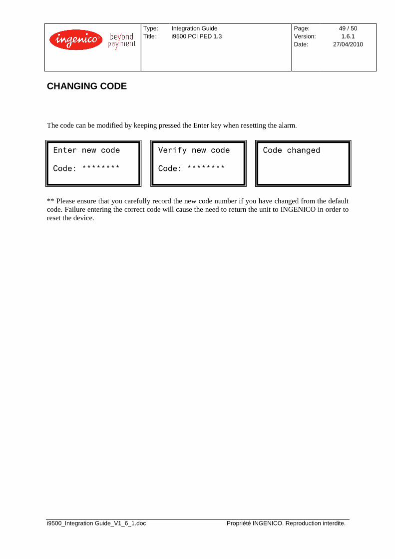
CHANGING CODE The code can be modified by keeping pressed the Enter key when resetting the alarm. ** Please ensure that you carefully record the new code number if you have changed from the default code. Failure entering the correct code will cause the need to return the unit to INGENICO in order to reset the device.
Enter new code Code: ********
Verify new code Code: ********
Code changed
Type: Title :
Integration Guide i9500 PCI PED 1.3
Page: Version: Date:
50 / 50 1.6.1
27/04/2010
i9500_Integration Guide_V1_6_1.doc Propriété INGENICO. Reproduction interdite.
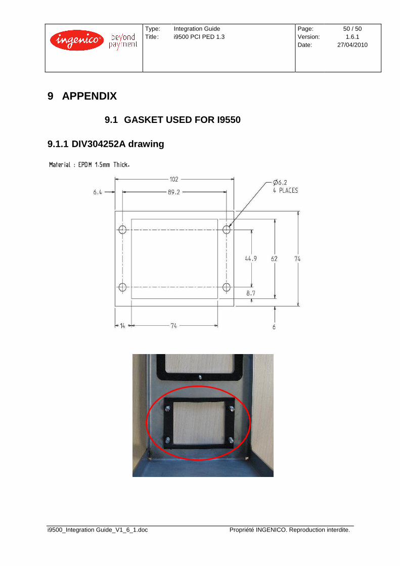
9 APPENDIX
9.1 GASKET USED FOR I9550 9.1.1 DIV304252A drawing