information systems, project management and cad in
TRANSCRIPT

Faculty of Science and Technology
MASTER’S THESIS
Study program/ Specialization:
• Offshore Technology - Marine and
Subsea Technology
• Offshore Field Development Technology
Spring semester, 2013
Open / Restricted access
Writer: Joachim Sannes
…………………………………………
(Writer’s signature) Faculty supervisor: Ove Tobias Gudmestad External supervisor(s):
• Stuart Cowie, Area Manager, Pipeline and Process Services Scandinavia, Halliburton. • Anatoly B. Zolotukhin, Gubkin Russian State University of Oil and Gas
Titel of thesis:
Hydrate plugs in subsea pipelines and non-invasive methodology for localization Credits (ECTS): 15 Key words: • Specifics of hydrates • Hydrate plugs • Plug formation • Non-invasive method for identification
Pages: 78 + enclosure: 1
Stavanger: June 30, 2013

© 2013 Joachim Sannes
| Abstract
i
ABSTRACT
With the growth in global energy demand and the lack of new shallow-water and onshore
opportunities, there is growing emphasis on oil and gas production in deep-water
environments. A particular challenge for flow assurance engineers is to ensure pipelines
remain free from restrictions created during operation.
Hydrate plugging, in particular is, one of the major flow assurance challenge, and as oil and
gas production moves into harsh and challenging environments, there is a growing challenge
to prevent hydrate plug formation. The applicability and efficiency of remediation methods
depend on locating an accumulation or plug, and novel techniques for accurate localization
and remediation are greatly required. A reflected review of various techniques is discussed in
an attempt to propose improvements.
The objective of this study is to carry out an interdisciplinary review to investigate whether
any existing technology can be adopted to address the challenges of locating hydrate
blockages in subsea pipelines. The challenge is complicated by the lack of methods to
accurately detect hydrate plugs in subsea pipelines.
The safety and economic costs associated with pipeline blockages are compelling the industry
to design an innovative means for effective and accurate localization of blockages in offshore
pipelines. Here, we indicate the motivation for hydrate science and engineering; that is, the
petroleum industries enormous need for solving the challenge of hydrates. This involves
teams composed of, among others; physicists, chemists and biologists to understand hydrate
origin, as well as teams composed of subsea specialists to develop inhibitory, locating and
remediation techniques. In this thesis, emphasis is placed on the major applications of hydrate
research: the nature of hydrates, how they occur in pipelines and remediation methods. An
introduction of hydrate structures and properties is presented. Subsequently consequences and
handling of hydrates in offshore pipelines is discussed.
After gaining an understanding of hydrate occurrence in subsea pipelines and having
reviewed detection methods related to full hydrate blockages, the advantages and

Abstract |
ii
disadvantages of each have been considered. The research conducted indicates that non-
invasive technologies exist for detecting full blockages and deposit profiling in liquid filled
pipelines, however a more accurate method needs to be developed for locating a full
blockage. In gas pipelines a method to both profile deposits within the pipeline and accurately
locate a full blockage has yet to be developed.

| Acknowledgments
iii
ACKNOWLEDGMENTS
First and foremost, I would like to express my very great gratitude to my Professor and
internal supervisor Ove Tobias Gudmestad, who devoted time and put a lot of effort in
guidance and assistance of my Thesis. With his enthusiastic encouragement and useful
critiques, as well as his academic experience, he supported me with valuable and constructive
suggestions during the planning and development of my Thesis.
I also wish to express my sincere gratitude to my external supervisor from Gubkin Russian
State University of Oil and Gas, Professor Anatoly Zolotukhin, for giving me the opportunity
to gain an international education by join the Double Master’s degree program between
University of Stavanger and Gubkin University in Moscow. I also would like to thank the
other members of this Double Masters’ degree committee; Professor Ove Tobias Gudmestad,
Bente Dale and Elisabeth Faret from the University of Stavanger and Associated Professor at
Gubkin University, Vladimir Balitskiy. Without them the study process following both
Universities’ requirements would be impossible.
Finally, I would like to express my gratitude to my external supervisor Stuart Cowie, Area
Manager at Halliburton, for making it possible to gain experience in the industry by
cooperating on the Thesis. I am particularly grateful for the valuable advice and support given
by the Halliburton team composed of the following specialists; Laurence James Abney, Neil
Mackay and Brian McGillivray.

Table of Content |
iv
TABLE OF CONTENT Abstract ....................................................................................................................................... i Acknowledgments ..................................................................................................................... iii Table of Content ........................................................................................................................ iv Table of Figures ....................................................................................................................... vii Table of Equations .................................................................................................................... ix List of Symbols .......................................................................................................................... x List of Abbrevations ................................................................................................................. xii
1 Introduction ................................................................................................... 1
1.1 World ocean Petroleum resources ............................................................................... 1
1.2 Flow assurance ............................................................................................................ 3
1.2.1 Pipeline transportation modes .......................................................................... 4
1.3 Blockages in pipelines ................................................................................................. 8
1.4 Conventional (intrusive) flow remediation solutions for pipelines ............................. 9
1.4.1 Handling Hydrates .......................................................................................... 10
1.5 Non-invasive methods ............................................................................................... 11
1.6 Context of this chapter to those that read .................................................................. 11
2 Nature of Hydrates...................................................................................... 13
2.1 Introduction ............................................................................................................... 13
2.2 Safety First: General Hydrate Plug Safety Considerations ....................................... 14
2.3 Natural gas hydrate structures and physical properties ............................................. 15
2.3.1 Crystal structures of ice Ih and natural gas hydrates ...................................... 16
2.3.2 Hydrate non-stoichiometry ............................................................................. 19
2.3.3 Brief statement of hydrate structure ............................................................... 20
2.3.4 Filling the hydrate cages ................................................................................. 21
2.4 The effect of NGH on the flow assurance ................................................................. 22
2.5 NGH Inhibition for subsea pipelines ......................................................................... 24
2.5.1 Inhibition with MeOH or MEG ...................................................................... 26
2.5.2 Early warning signals ..................................................................................... 26
2.6 Summary: nature of hydrates ..................................................................................... 27
3 How do hydrate plugs occur in subsea pipelines? ................................... 28
3.1 Introduction ............................................................................................................... 28
3.2 Extended pipelines and deeper and colder waters ..................................................... 28
3.3 Deep-water operations ............................................................................................... 29
3.4 Arctic offshore hydrocarbon fields ............................................................................ 29

| Table of Content
v
3.4.1 Seabed permafrost thaw settlement ................................................................ 31
3.5 Hydrate formation and dissociation processes .......................................................... 31
3.5.1 Hydrate formation by the Joule-Thomson effect ............................................ 33
3.5.2 Locations of hydrate blockage ........................................................................ 34
3.5.3 Conceptual Overview: Hydrate Plug Formation in Oil-Dominated Systems. 35
3.5.4 Conceptual overview: Hydrate Formation in Gas-Dominated Systems ......... 37
3.5.5 Concept of hydrate blockage formation ......................................................... 38
3.6 Hydrate plug remediation .......................................................................................... 39
3.7 Summary: how do hydrate plugs occur in subsea pipelines? .................................... 39
4 Techniques to detect and locate hydrate plugs ........................................ 40
4.1 Introduction ............................................................................................................... 40
4.2 Detecting and dealing with hydrate formation .......................................................... 41
4.2.1 OLGA – “Oil and Gas Simulator” .................................................................. 41
4.3 Detection of hydrate plug location ............................................................................ 42
4.3.1 Non-invasive methods .................................................................................... 42
4.4 The Pressure-Pulse Method for Multi-Phase Metering ............................................. 43
4.4.1 Introduction .................................................................................................... 43
4.4.2 Basic Principles .............................................................................................. 44
4.4.3 Key features of the Pressure-Pulse Method .................................................... 51
4.5 Acoustic reflectometry .............................................................................................. 52
4.6 Pipeline diameter expansion variation measurements ............................................... 52
4.7 Radiographic detection .............................................................................................. 53
4.8 The methodology which “looks” into the pipeline .................................................... 53
4.8.1 Traverse Gamma Detection Method ............................................................... 54
4.8.2 X-ray detection Method .................................................................................. 55
5 Discussion ..................................................................................................... 56
5.1 Introduction ............................................................................................................... 56
5.2 What we know about any pipelines ........................................................................... 56
5.3 What is the ideal method? ......................................................................................... 57
5.4 Existing methods for localization of hydrate plugs ................................................... 58
5.5 The applicability of localization methods ................................................................. 59
5.6 What are the limitations for the existing methods? ................................................... 60
5.6.1 Pressure-Pulse Method ................................................................................... 60
5.6.2 Acoustic reflectometry ................................................................................... 60
5.6.3 Pipeline diameter expansion variation measurements .................................... 61
5.6.4 Radiographic detection ................................................................................... 61
5.6.5 Injection of inhibitor ....................................................................................... 62

Table of Content |
vi
5.6.6 Back pressurization ......................................................................................... 62
5.6.8 Subjective evaluation of the methods ............................................................. 63
6 Conclusion .................................................................................................... 65
7 Technology for the future ........................................................................... 66
7.1 The industries need for innovative solutions ............................................................. 66
7.2 Interdisciplinary technology adoption ....................................................................... 67
7.3 Optoelectronic technologies for the oil and gas industry .......................................... 68
7.4 Tracerco’S discovery ................................................................................................. 69
7.5 Summary: technology for the future .......................................................................... 70
8 References .................................................................................................... 71
9 Annex A .......................................................................................................... 1

| Table of Figures
vii
TABLE OF FIGURES
Figure 1.1-1 Global energy consumption [91] ........................................................................... 1 Figure 1.1-2 World ocean Hydrocarbon resources [2] ............................................................... 2 Figure 1.2-1 Multiphase flow [4] ............................................................................................... 3 Figure 1.2-2 Dense-phase pipeline flow [3] ............................................................................... 6 Figure 1.2-3 Oil phase diagram [3] ............................................................................................ 7 Figure 1.3-1 Hydrate plug formed in a subsea pipeline (Brazil) [95] ........................................ 8 Figure 2.3-1 Hydrate crystal unit structure, a) sI [61], b) sII and c) sH [62] ........................... 16 Figure 2.3-2 Cavities in gas clathrate hydrates [78] ................................................................. 19 Figure 2.3-3 the three common hydrate unit crystal structures [78] ........................................ 19 Figure 2.3-4 Comparison of guest molecule size and cavities occupied as simple hydrates [64] .................................................................................................................................................. 21 Figure 2.4-1 Pressure- temperature diagram for hydrate formation [15] ................................. 23 Figure 2.5-1 Pressure-temperature limitations for Hydrate inhibitors [15] ............................. 25 Figure 3.4-1 Petroleum resources in the Arctic [2] .................................................................. 30 Figure 3.5-1 Hydrate formation curve [45] .............................................................................. 33 Figure 3.5-2 hydrate plug formations in "s" shapes ................................................................. 34 Figure 3.5-3 A conceptual illustration of hydrate formation via aggregation in an oil-dominated system [38] ............................................................................................................. 35 Figure 3.5-4 Conceptual illustration of hydrate shell growth [38] ........................................... 36 Figure 3.5-5 Hydrate blockage formation [36] ........................................................................ 37 Figure 3.5-6 Hydrate accumulation in gas pipeline [39] .......................................................... 38 Figure 4.1-1 Pipeline pressure drops due to hydrates .............................................................. 40 Figure 4.4-1 Water-hammer measured on a quick-acting valve [49] ...................................... 45 Figure 4.4-2 Pressure pulse set-up for a pipeline [50] ............................................................. 46 Figure 4.4-3 Pressure pulse at locations A and B up-stream a quick-acting valve [50] .......... 46 Figure 4.4-4 Line-packing measured after the closing of a quick-acting vale [49] ................. 47 Figure 4.8-1 Visibility into the pipeline [4] ............................................................................. 53 Figure 4.8-2 Traverse gamma [30]. ......................................................................................... 54 Figure 4.8-3 X-ray detection [30]. ........................................................................................... 55 Figure 5.2-1 what we know about any pipelines ...................................................................... 56 Figure 5.6-1 Evaluation Pressure-Pulse Method ...................................................................... 60 Figure 5.6-2 Evaluation acoustic reflectometry ....................................................................... 60 Figure 5.6-3 Evaluation pipeline diameter expansion variation measurements....................... 61 Figure 5.6-4 Evaluation radiographic detection ....................................................................... 61 Figure 5.6-5 Evaluation injection of inhibitor .......................................................................... 62 Figure 5.6-6 Evaluation back pressurization ............................................................................ 62 Figure 5.6-7 Subjective evaluation of methods ........................................................................ 63 Figure 7.2-1 Multipurpose Supply AUV [98] .......................................................................... 67 Figure 7.2-2 Inspection and communication AUV [98] .......................................................... 67 Figure 7.3-1 Obscuration sensor [97] ....................................................................................... 68 Figure 7.4-1 Tracerco's Discovery [102] ................................................................................. 69

List of Tables |
viii
LIST OF TABLES Table 2.3-1Geometry of cages, see below for legend .............................................................. 18 Table 5.5-1 ............................................................................................................................... 63

| Table of Equations
ix
TABLE OF EQUATIONS Equation 4.2-1, Joukowsky equation [50] ................................................................................ 45 Equation 4.2-2 [50] .................................................................................................................. 46 Equation 4.2-3 [50] .................................................................................................................. 47 Equation 4.2-4 [50] .................................................................................................................. 47 Equation 4.2-5 [50] .................................................................................................................. 48 Equation 4.2-6, Wood equation [83] ........................................................................................ 48 Equation 4.2-7 [83] .................................................................................................................. 48 Equation 4.2-8 [83] .................................................................................................................. 48 Equation 4.2-9 [85] .................................................................................................................. 49 Equation 4.2-10 [85] ................................................................................................................ 49 Equation 4.2-11 [85] ................................................................................................................ 49

List of Symbols |
x
LIST OF SYMBOLS Latin symbols/ characters sI, Cubic structure sII Cubic structure sH Hexagonal structure Å 1Å = 10−10 𝑚 𝑖 Face type 𝑚𝑖 Number of faces 𝑛𝑖 Number of edges S Salinity ∆𝑝𝑎 Water-hammer (Pa) u Homogenous fluid velocity (m/s ) a Speed of sound (m/s) 𝑤 Mass flow rate (𝑘𝑔/𝑠) 𝐴 Cross-section area 𝑚2 𝑓 Friction factor (𝑑𝑖𝑚𝑒𝑛𝑠𝑖𝑜𝑛𝑙𝑒𝑠𝑠) 𝐶𝑝 Isobaric specific heat 𝐶𝑣 Isochoric specific heat 𝐾𝑆 Isentropic compressibility 𝐾𝑇 Isothermal compressibility 𝑑 Pipe diameter (𝑚) S Isentropic T Isothermal processes

| List of Symbols
xi
Greek symbolscharacters 𝜌 Fluid density (kg/𝑚3) ∆𝑡 Time-of-flight ∆𝐿 Pipe length (not the same distance as ∆𝐿𝑎𝑏) (𝑚) 𝛼 Void fraction (𝑑𝑖𝑚𝑒𝑛𝑠𝑖𝑜𝑛𝑙𝑒𝑠𝑠) (M) Mixture (G) Gas (L) Liquid γ Ratio of specific heats

List of Abbrevations |
xii
LIST OF ABBREVATIONS NGH Natural gas hydrates THI Thermodynamic inhibitors KI Kinetic inhibitors AA Anti-agglomerates MEG Monoethylene glycol OLGA An Oil and gas simulator computer program LDHI Low dosage hydrate inhibitor W/O Water in oil FPSO Floating production Storage and Offloading ROV Remote Operated Vehicle AUV Autonomous Underwater Vehicle NGL Natural Gas Liquids

World ocean Petroleum resources | Introduction
Hydrate plugs in subsea pipelines and non-invasive methodology for localization | 1
1 INTRODUCTION
1.1 WORLD OCEAN PETROLEUM RESOURCES
With the growth in global energy demand, the world’s ocean hydrocarbon reserves (Figure
1.1-2) (production targets) will be of increasing importance. Oil and gas will remain the main
energy sources in the long-term perspective (see Figure 1.1-1), and a significant amount of
these resources are located in deep-water environments. In these environments flow assurance
is of ever increasing importance as the temperatures at these depths are low, in some places at
-1.9ºC, which is the freezing point of salt water (Rule-of-Thumb 1). The specialists
responsible for flow assurance in subsea pipelines are facing a tremendous challenge of
ensuring that pipelines remains free of obstructions[1][2].
Figure 1.1-1 Global energy consumption [91]
The oil industry is currently working under completely different circumstances than thirty
years ago. The oil companies have a desire to develop marginal fields far from land, and at
other nodes at greater water depths than before. Oil recovery can now be accomplished down
to 3000 meter of water. At such extreme depths, the seawater is cold, which increases the risk
of hydrate formation in pipelines [5].
Flow assurance challenges in pipelines include hydrate formation, paraffin wax deposition,
asphaltene deposition, sand deposits, black powder, and on the wall of pipelines, all of which
obstruct the flow of well fluids and associated produced hydrocarbons. The focus in this

Introduction | World ocean Petroleum resources
2 | Hydrate plugs in subsea pipelines and non-invasive methodology for localization
thesis, however, is directed to blockages formed by hydrates. The quest for a non-invasive
method to locate obstacles in flow lines and pipelines will be described and assessed. The
significant factors that motivate the use of a non-invasive remediation system will also be
discussed.
The oil industry prepares for longer pipelines in deeper and colder waters. Due to expensive
interfield subsea separation systems, it is essential to be able to transport multiphase fluids in
the same pipe to the nearest processing facility, offshore or onshore. This is still the case in
the North Sea, therefore, for new, extended pipelines located far away from shore and in deep
water environments, flow assurance is of even increasing importance. Definitely something
the industry needs to place emphasis on and be prepared for [5].
Figure 1.1-2 World ocean Hydrocarbon resources [2]
When oil, water and gas flow freely in the same pipe from the well to land, or to a platform
far away, it is essential to know what happens in the pipe along the way. How does this
complex flow behave when it is transported mile after mile, and is there any risk of hydrate
formations? In fact there are no detailed measurements during this transportation, and in order
to gain knowledge about what happens during this phase one need theories, models and
verification of models [5].
Moreover, it is important to look at how the flow will change during the whole operating life
of the pipeline. Typically, the reservoir pressure will decline, and the well will produce more
water compared to oil and gas. The more liquid in the flow line relative to gas, the more
challenging it is to transport the multiphase flow. Transport pipelines are often laid along
slopes because of the topography of the seabed. This may induce slugging, a continuous
liquid plug that threatens the flow assurance [5].

Flow assurance | Introduction
Hydrate plugs in subsea pipelines and non-invasive methodology for localization | 3
1.2 FLOW ASSURANCE
There are large challenges facing the oil and gas industry, among those are transportation of
hydrocarbons. This study addresses the flow assurance during the transfer of hydrocarbons
from a reservoir to processing facilities. The main objective with this study is to identify an
optimal solution in order to locate blockages in pipelines [3].
«The term “flow assurance” is thought to have been introduced by Petrobras in the early
1990s as ‘Garantia de Fluxo’ which literally translates as ‘Guarantee the Flow’, or Flow
Assurance» [9].
The term originally covered the thermal hydraulic and production chemistry technical issues,
faced when exploiting deep-water oil reserves. In recent times this term is generally
interpreted in a much broader definition:
“Safe, uninterrupted and simultaneous transport of gas, oil and water from reservoirs to
processing facilities” [9].
Flow assurance refers to a multidiscipline process where the aim is a successful, safe and
uninterrupted transport of hydrocarbons from a reservoir to processing facilities. The
hydrocarbons typically flow through the pipelines as a mixture of oil, gas, some solids and
water. This is often referred to as a multiphase transport, which is a simultaneous flow
consisting of gas, oil, water and sometimes solids through a pipeline [3]. Flow assurance
solutions should cover the interactions among the reservoir, the well, the pipeline, and the
process facilities [9].
Figure 1.2-1 Multiphase flow [4]

Introduction | Flow assurance
4 | Hydrate plugs in subsea pipelines and non-invasive methodology for localization
The basis for effective multiphase transport involves advanced fluid mechanic, flow
simulation tools, and in-depth understanding of fluid behavior [3]. Flow assurance can be
described as a systematic engineering analysis that utilizes the in-depth knowledge of fluid
properties and the thermal-hydraulic state of the system to develop strategies for control of
formation of solids such as hydrates, wax, asphaltenes and scale. All this conditions
(including a few other mentioned in section 1.3) of a particular field have to be well
understood for the purpose of preventing and act with regard to the flow problems which can
potentially arise. The flow assurance process, including its scope and the factors that have
driven its development will be discussed in this study [10].
1.2.1 Pipeline transportation modes In general, pipelines can be classified in three categories depending on purpose [87]:
i. Gathering pipelines
• Group of smaller interconnected pipelines which forms well organized and
reasonably constructed networks with the purpose of bringing oil or natural gas
from several nearby wells to a processing facility. These pipelines are normally
short, a couple of hundred meters and with small diameters.
ii. Transportation pipelines
• Primarily long onshore or offshore lines with large diameter, carrying products
(oil, gas, refined products) between cities, countries and even continents. These
transportation networks comprise several compressor stations in gas lines or
pump stations for crude and multiproduct pipelines.
iii. Distribution pipelines
• Comprises several interconnected pipelines with small diameters bringing the
products to the final consumer.
1.2.1.1 Oil pipelines
Oil pipelines are made of steel tubes and are typically applied with diameters ranging from 4
to 48 inches. The oil is held in motion by pump stations along the line, and flows at speed of
approximately 1 to 6 m/s [87].

Flow assurance | Introduction
Hydrate plugs in subsea pipelines and non-invasive methodology for localization | 5
1.2.1.2 Multiphase pipelines
Multi-product pipelines transport two or more different products simultaneously in the same
annulus pipe. Usually there is no physical separation between the different products and is
often referred to as multiphase flow [87].
1.2.1.3 Gas pipelines
For natural gas, pipelines are constructed of carbon steel with a diameter ranging from 2 to 60
inches, depending of the type of line. Compressor stations along the line are keeping the gas
pressurized [87]. Natural gas pipelines can be tens or even hundreds of kilometers long and
the lack of instrumentation along the length of the pipeline means that it is difficult to locate
any blockage with any degree of accuracy.
1.2.1.3.1 Singles-phase gas transportation
Single-phase gas transportation refers to the flow of gaseous hydrocarbons in a pipeline,
where the presence of liquids should be avoided. For single-phase gas lines, the hydrocarbon
and water dew points are critical factors. The dew point (Figure 1.2-2) of a gas at a certain
pressure is the temperature at which liquids will start to precipitate. The consequences of not
meeting the dew point requirements may be severe and very threatening for the flow
assurance. In case of hydrocarbon liquid precipitation, the risk of hydrate formation inside a
pipeline system is present with the excess of free water [3].
1.2.1.3.2 Single-phase liquids transportation
Single-phase liquids transportation involves the movement of hydrocarbon liquids in pipeline
systems, typically crude oil, where the occurrence of free gas should be prevented. Heavier
gas components (NGLs), are often included in the flow of crude oil or condensate. When
maintaining a sufficient pressure in order to avoid the formation of free gas, crude oil or
condensate still be transported in a single-phase pipeline. The pipeline pressure should, at any
time, be maintained above the vapor pressure of the liquid [3].
1.2.1.3.3 Two-phase flow
Two-phase flow involves transportation of gas and liquids (typically condensate) in separate
phases together in a pipeline. When gas and condensate (in separate phases) flow currently in

Introduction | Flow assurance
6 | Hydrate plugs in subsea pipelines and non-invasive methodology for localization
a pipeline, liquid accumulations in low points of the pipeline topography may cause flow
restrictions. To prevent any effect of this, special sweeping pigs are regularly run through the
flow-line to push out the liquid-buildups [3].
1.2.1.3.4 Multiphase gas and liquid flow
A multiphase flow system is the simultaneous transport of liquid hydrocarbons, gas, water
and solid particles in a pipeline. The hydrocarbon liquids are the predominant flow
component. The main challenge for such oil-dominated systems is the pressure drops along
the line, thus the selection of pipeline diameter is highly essential in relation to maintain a
satisfactory flow to arrive at the host facility.
Figure 1.2-2 Dense-phase pipeline flow [3]
1.2.1.3.5 Multiphase gas-condensate systems
Multiphase gas-condensate systems are pipelines carrying hydrocarbon liquids, gas, water and
solids, where gas is the predominant flow component. In such pipeline systems, it is
substantial to predict water and condensate accumulations to ensure flow assurance.

Flow assurance | Introduction
Hydrate plugs in subsea pipelines and non-invasive methodology for localization | 7
1.2.1.3.6 Gas and liquids in dense phase (supercritical flow)
Figure 1.2-2 shows the pressure- temperature relationship for rich gas mixture from Statfjord
and nearby oilfields. This phase curve represents the bubble point line and the dew point line
of the mixture. The area under the curve represents the two-phase equilibrium between gas
and liquids. At any point outside the curve the mixture is in single-phase, either as gas, liquid,
or dense phase. Dense phase is a state similar to a vapor and is occurring at pressures above
the cricondenbar, which is the apex of the curve. The pressure at this point is the maximum
pressure at which two phases can exist [3].
The most crucial flow assurance issue when operating a dense-phase pipeline is to stay above
the cricondenbar for the actual rich gas mixture. If the condition drops under this point,
condensation of liquids and slugging may upset the gas flow [3].
Figure 1.2-3 Oil phase diagram [3]
Figure 1.2-3 illustrates an oil phase diagram. Depending on the routing, design and the
operation of the production and pipeline system the different boundaries illustrated in the
diagram may be crossed. As the oil flows through the flow-line, its pressure and temperature
decrease. As the temperature and pressure decrease, the bubble point line (thick curved line)
is reached, which gas starts to migrate out of the liquid mixture. In other words, from this
point on, a two-phase flow regime is present [3].

Introduction | Blockages in pipelines
8 | Hydrate plugs in subsea pipelines and non-invasive methodology for localization
The bubble point line represents a boundary condition comprising 100% liquids. Each of the
thinner curves shows a 10% increase in evolved gas volume. How the hydrocarbons behave
as the temperature and pressure changes along the pipeline can be understood from the phase
diagram. On this basis, assumptions about the occurrence of flow-impending physical-
chemical phenomena such as asphaltenes, wax and hydrates can be carried out [3].
1.3 BLOCKAGES IN PIPELINES
Piping systems are similar to arteries and veins of the human body. Pipelines are a suitable
and most economical solution for transportation of hydrocarbons for long distances; however,
risks associated with blockage formation of transported products are still high. The worldwide
floe assurance investments are considerable. In a 1999 survey of 110 energy companies, flow
assurance was listed as the major technical issue related to offshore projects [37]. This is still
a key issue where hydrates (Figure 1.3-1) are considered to be the largest problem by an order
of magnitude to the others.
Blockages or restrictions are one major issue for the pipeline system. They occur as a result of
the building up of different substances such as wax, asphaltenes, sand, hydrates and black
powder from corrosion products, and emulsions [11]. At certain favorable conditions, these
depositions begin to grow and are then reducing the inner diameter of the pipeline until they
have agglomerated to block the entire span of a pipeline section. These deposits are primarily
due to changes in flow condition such as; temperature, pressure and flow velocity, and
reactions between component fluids.
Figure 1.3-1 Hydrate plug formed in a subsea pipeline (Brazil) [95]

Conventional (intrusive) flow remediation solutions for pipelines | Introduction
Hydrate plugs in subsea pipelines and non-invasive methodology for localization | 9
The hydrate plugs (Figure 1.3-1) can form quickly and complete block a pipeline. The steps to
be taken in remediating a subsea pipeline are to locate, identify and remove the obstruction.
The accurate evaluation of the blockage is a fundamental part of this remediation process.
Due to the variety of pipeline layout and facilities, there is no universal solution for detecting
plugs in all conditions [88]. The conventional methods for blockage detection include flow
pressure monitoring detection, diameter expansion measurement and radiographic techniques
[1]. The flow pressure monitoring detection is in this thesis referred to as the Pressure- Pulse
Method, see section 4.2.3.
External mechanical damages due to dents are recognized as a severe and common form of
mechanical damages which leads to reduction of the inner pipeline diameter.
1.4 CONVENTIONAL (INTRUSIVE) FLOW REMEDIATION SOLUTIONS FOR PIPELINES
The risk to petroleum production from the accumulation of deposits or blockages in pipelines,
resulting in the reduction or elimination of the pipeline flow area, is faced every day by the
hydrocarbon transportation section of the industry. Conventional procedures for pipeline
remediation to remove these obstacles introduce the means of periodic and extensive pigging,
chemical injection through umbilicals and high performance thermal insulation [8].
Flow assurance challenges related to a deep-water flowline are considerably different from
the flow assurance challenges for shallow water transport flowlines. Usually, where a flow
path remains through the pipeline, measures can be taken to stop or reverse the deposition or
deposit accumulation process. These actions may be a methodical program for the removal of
the accumulations by utilizing pipeline pigs or through the use of some type of deposit
inhibitor or a combination of these two. On the other hand, in extreme instances where the
flow path is entirely blocked, an intrusive intervention system is required.
Deposits/sediments can be categorized as either organic or inorganic. The inorganic deposits
are caused by chemical reactions of formation waters and commonly called scale. Organic
deposits are derived from the alteration from normal conditions. These changes affect the

Introduction | Conventional (intrusive) flow remediation solutions for pipelines
10 | Hydrate plugs in subsea pipelines and non-invasive methodology for localization
chemical equilibrium so that the various materials in the crude oil are no longer held in
solution but separated out and deposited.
A major challenge for the flow assurance is the formation of hydrate plugs (chapter 3) due to
high pressure and low temperature at the seafloor. On the other hand, in terms of hydrate plug
formation in transport pipelines, there are actually more severe safety concerns. Especially
with regard to removal of the hydrate plugs. During the dissociation of hydrate plugs in
pipelines, a great pressure drop occurs at the moment when the plug detaches from the pipe
wall. Due to the pressure difference the plug can be launched like a projectile. This
phenomenon will press the downstream gas further and could cause ruptures and damages in
pipeline or might cause a blowout [23].
1.4.1 Handling Hydrates Hydrate dissociation by heating causes rapid gas pressure increase in the system. In order to
determine the best approach to remediation of hydrate blockages, the knowledge of the
location and length of the plug is very critical. During plug dissociation, there might be
multiple plugs existing in the pipeline which threatens the pipe both from safety and technical
perspective. According to investigations developed by Canadian Association of Petroleum
Producers there some important key points to consider in that context [24];
i. Always assume multiple hydrate plugs in the flow loop. There may be a high pressure
point between two plugs.
ii. Attempting to move hydrate plugs can rupture pipes and vessels in the flow loop
iii. While heating a plug the heating procedure should commence from the end of a plug
rather than at the middle section of the pipe.
iv. Single sided depressurization can totally launch a plug like a high-speed bullet and
result in ruptured pipes, damaged equipment and uncontrolled release of hydrocarbons
to the environment.
v. Actively heating a hydrate plug needs to be done in such way that any released gas
will not be trapped.

Non-invasive methods | Introduction
Hydrate plugs in subsea pipelines and non-invasive methodology for localization | 11
Do not attempt to remove hydrates by force through increased or decreased pressure on either
side of the plug. Partially hydrate systems, where the plug is about to be formed but still not
completely blocked the line, can be handled with inhibitors. Naturally, one must first change
the conditions that initially led to the hydrates. Depressurization with intent to step out of the
hydrate formation zone is a common procedure (see section 3.5.1) [28].
1.5 NON-INVASIVE METHODS
During the last decades, several experiments have been carried out, particularly in the oil and
gas industry to study blockages in pipelines. Numerous experiments have been performed
using acoustic waves or sound emissions radiation to identify the exact location of blockages.
Three possible methods to unlock gas trapped in the hydrate plugs have been well-
documented, which are as follows [23];
i. Reduce the pressure in the reservoir below the hydrate- equilibrium pressure.
ii. Increase the temperature above the hydrate- equilibrium temperature.
iii. Inject chemicals to dissociate the plug.
It should be noted that we emphasis on non-invasive methods as any invasive methods will
complicate the search for plugs and cause delays when the plugs are released and the normal
flow can be retained. Furthermore, equipment inserted in the pipeline may easily get stuck in
the pipeline.
1.6 CONTEXT OF THIS CHAPTER TO THOSE THAT READ
With the overview provided by the current chapter, a broad review of ongoing research is
carried out in order to give the reader an idea of the importance of the hydrate challenges and
how the industry is searching for a solution. A brief description of the following chapters is
given as follows:
Chapter 2 presents the fundamentals of the chemical structure of hydrates in the attempt to
answer the question; “what are hydrates?” Safety considerations, the effect of hydrates on

Introduction | Context of this chapter to those that read
12 | Hydrate plugs in subsea pipelines and non-invasive methodology for localization
flow assurances, and early warning of the risk of hydrate formation in pipelines is
important topics that are touched.
Chapter 3 presents a description on the hydrate growth, agglomeration and fundamentals on
how hydrate plugs occur in subsea pipelines.
Chapter 4 provides an overview of existing techniques to detect and locate hydrate plugs in
offshore pipelines. The Pressure-Pulse Method is particularly emphasized.
Chapter 5 discusses the various localization methods and evaluates them against the “ideal”
method.

Introduction | Nature of Hydrates
Hydrate plugs in subsea pipelines and non-invasive methodology for localization | 13
2 NATURE OF HYDRATES
2.1 INTRODUCTION
The use of offshore pipelines is in recent years implemented in deep- and ultra-deep-water
fields at low temperature and high pressure. As the development goes towards deeper and
deeper oil and gas fields, the lower temperature and often high pressure conditions in
pipelines on the seafloor may cause natural gas and water transported in the pipelines to form
gas hydrates. Upon formation, hydrate accumulation and agglomeration eventually form a
slug, blocking the entire annulus in the pipeline. Obviously, these slugs will obstacle the flow
of hydrocarbons. For that reason more and more attention has been paid to developing flow
assurance strategies to prevent hydrate plug formation [14].
Hydrates are one of the major challenges that affect operations in the oil and gas. Since the
discovery of hydrates, much research work has been done with focus on the determination of
hydrate structure, kinetics of the hydrate formations, thermodynamic behavior and
mechanisms to avoid plugging in pipelines.
Gas hydrates can form at any location where free gas, water, and the appropriate temperature
and pressure exists in space, in the atmospheres on the earth’s surface, inside of the earth or in
technical systems of production, transportation and processing of hydrocarbons [46].
The best way to understand hydrates is to look at the natural seepage from the seafloor.
Obviously there is a tremendous access to water; the gas comes out of the seabed and due to
the high hydrostatic pressure and the low temperature this process is drawn into the hydrate
zone. Most components of natural gases (other than H2, He, Ne, n-C4H10 and heavier alkanes)
are capable of forming hydrates (see Figure 2.3-4). An interest toward submarine hydrates is
primarily caused by the fact that they are regarded as part of the hydrocarbon reserves [96].
Gaining an understanding of the submarine gas hydrate formation in the oceanic lithogenesis
as well as specific features of the geothermal field caused by energy capacity of hydrate
formation and dissociation is important for the theory development in order to draw parallels

Nature of Hydrates | Safety First: General Hydrate Plug Safety Considerations
14 | Hydrate plugs in subsea pipelines and non-invasive methodology for localization
to flow assurance in subsea pipelines. Detailed description on hydrate formation is given in
section 2.3.
This chapter focuses on the question, “what are hydrates?” Background material on hydrate
structures and formation mechanism, prevention and remediation methods, figures and
diagrams are the basis for this chapter [35].
2.2 SAFETY FIRST: GENERAL HYDRATE PLUG SAFETY CONSIDERATIONS
This subchapter presents some of the potential dangers associated with hydrate plugs. Many
instances of line rupture, sometimes accompanied by loss of life, are attributed to the
formation of hydrate plugs. Three characteristics of hydrates contribute to safety issues [35];
i. Hydrate density is similar to ice, and upstream pressure can accelerate a loosen
hydrate plug up to very high velocities approaching the speed of sound [28]. Such
velocities and the masses of the plugs provide sufficient momentum to cause major
damages. While attempting to push hydrate plugs, their mass and velocity can cause
two types of failure: damage to orifices, valves and elbows; and pipe rupture
downstream of the hydrate caused by extreme gas compression [29].
ii. Hydrates can form either single or multiple plugs, with no method to predict which
will occur. Always assume the presence of multiple hydrate plugs [29]. High
differential pressures can be trapped between plugs. Plugs with a length of up to one
and a half kilometers are observed [34].
iii. Hydrates contain as much as 180 volumes of gas at standard temperature and pressure
(STP) per volume of hydrate. When hydrate plugs are dissociated by heating, any
confinement causes rapid gas-pressure increase. Thermal treatment is no applicable for
subsea pipelines. Any heating should be done form the one of the ends of the plug and
not from the center. Gradually depressurizing a plug from both sides is rather
preferred [29].
Field engineers discuss the “hail-on-a-tin-roof” phenomena, which refers to the rapid gas
pressure increase by heating the hydrates. Accumulations of hydrates can form large masses
that occupy appreciable volumes, often filling several hundred meters of the pipeline length.
With aspiration to blow the plug out of the flowline by increasing upstream pressure (see

Natural gas hydrate structures and physical properties | Nature of Hydrates
Hydrate plugs in subsea pipelines and non-invasive methodology for localization | 15
Appendix A, Rule-of-Thumb 1.) means additional hydrate formation and might cause pipeline
rupture [35].
2.3 NATURAL GAS HYDRATE STRUCTURES AND PHYSICAL PROPERTIES Hydrates are a mixture of water and gas molecules that crystallize to form a solid “ice plug”
under appropriate conditions of pressure and temperature. An unusual characteristic of
hydrates is that their formation is not strictly temperature dependent.
Natural gas hydrates are crystals formed by water with natural gases and associated liquids in
a ratio of 85 mol% water to 15% hydrocarbons. The hydrocarbons are encaged in ice-like
solids that do not flow but rapidly grow and agglomerate to sizes that can block flowlines.
Hydrates can form anywhere and at any time where hydrocarbons and water are present at the
right temperature and pressure (Figure 3.5-1).
Natural gas hydrates (NGH) form in unprocessed multiphase flow as a result of crystallization
occurring around the guest molecules at certain operating temperature and pressure
conditions.
Gas hydrates are solid crystalline compounds, which have a structure wherein guest
molecules are enmeshed in a grid-like lattice of the host molecules without forming a
chemical bound [29]. The water molecules are referred to as the host molecule, and the other
substances, which stabilize the crystal, are called the guest molecule. Hydrate crystals appears
in complex three-dimensional structures where the water molecules form a cage, and the guest
molecules are entrapped in the cages. The hydrogen bonds which form are the governing
factor for the structure that occurs. The presence of the essential guest molecules causes the
aligned molecules to stabilize, and a solid compound occurs [29]. No hydrate without guest
molecules has been found in the nature. Hence, hydrates are stable in the presence of the weak
attractive interactions between the guest- and the water molecule.

Nature of Hydrates | Natural gas hydrate structures and physical properties
16 | Hydrate plugs in subsea pipelines and non-invasive methodology for localization
2.3.1 Crystal structures of ice Ih and natural gas hydrates In this section, hydrate crystalline cavities, structures and similarities to ice are considered.
The reader is referred to reviews by [36], [57], [58], [59], with the additional and substantial
work on molecular motions reviewed by [60] for further details not emphasized in this thesis.
The emphasis is given to the hydrate structures; sI, sII and sH since these are by far the most
common natural gas hydrate structures.
2.3.1.1 Hydrate crystal structure and hydrate type definitions
In the late 1940s and early 1950s, von Stackelberg and associates concluded two decades of
x-ray hydrate crystal diffraction experiments at the University of Bonn. The understanding of
these experiments by [64], [65], [66], [67], [68], [69], [70] and [71] led to the finding of two
hydrate structures, sI and sII, as illustrated in Figure 2.3-1.
Figure 2.3-1 Hydrate crystal unit structure, a) sI [61], b) sII and c) sH [62]

Natural gas hydrate structures and physical properties | Nature of Hydrates
Hydrate plugs in subsea pipelines and non-invasive methodology for localization | 17
The presence of a third hydrate structure sH was discovered in 1989 [72]. The hydrate crystal
unit structure of sH is shown in Figure 2.3-1 c). Thus, as we can see from
Figure 2.3-1, all common natural gas hydrates appears to be of crystal structures, cubic
structure sI, cubic structure sII, or hexagonal structure sH.
2.3.1.2 Molecular structures and similarities to ice The structure of the three types of hydrate mentioned in 2.3.1.1is very often compared to the
most common water solid, hexagonal ice Ih. The biggest difference is that ice forms as a pure
component, while hydrates will not form without the existence of a guest molecule of
appropriate size [36].
The Structure sI is combined with guest molecules having diameter between 4,2 and 6 Å,
such as methane, ethane, carbon dioxide and hydrogen sulfide. Smaller guest molecules as
nitrogen and hydrogen (𝑑 < 4,2 Å) form structure sII. The same applies to larger molecules,
such as propane or iso-butane (6 Å < 𝑑 < 7 Å). Even larger molecules (typically7 Å < 𝑑 <
9 Å), such as iso-pentane or neohexane can form sH associated with smaller molecules such
as methane, hydrogen sulfide or nitrogen [36].
Despite the fact that the hydrates form only in the presence of a guest molecule, many of the
hydrate mechanical properties resemble those of ice Ih. This is partly because all three
common hydrate structures consist of approximately 85% water on a molecular basis. Yet,
there are some exceptions to this scientific theory, among them are the yield strength, thermal
expansion and thermal conductivity [36].
2.3.1.3 The cavities in hydrates The hydrate structures (Figure 2.3-3) are composed of five polyhedrons1formed by hydrogen-
bonded water molecules illustrated in Figure 2.3-2, with properties arranged in Table 2.3-1.
1 Geometric solid in three dimensions with flat faces and straight edges. The body is bounded by the faces, and as a rule the volume is enclosed by them [63].

Nature of Hydrates | Natural gas hydrate structures and physical properties
18 | Hydrate plugs in subsea pipelines and non-invasive methodology for localization
Table 2.3-1Geometry of cages, see below for legend
Geometry of Cages Hydrate crystal structure sI sII sH
Cavity Small Large Small Large Small Medium Large
Description 512 51262 512 51264 512 435663 51268
Number of Cavities 2 6 16 8 3 2 1
Average cavity radius2(Å) 3,95 4,33 3,91 4,73 3,943 4,04 5,79
Variation in radius4 (%) 3,4 14,4 5,5 1,73 4,0* 8,5* 15,1*
No. of water molecules/cavity5 20 24 20 28 20 20 36
For these polyhedrons, a nomenclature description (𝑛𝑖𝑚𝑖) was suggested [73], where 𝑛𝑖 is the
number of edges in face type “𝑖”, and 𝑚𝑖 is the number of faces with 𝑛𝑖 edges. Such as the
pentagonal6 dodecahedron7, a) of Figure 2.3-2, is described by 512 (𝑛𝑖 = 5, 𝑚𝑖 = 12)
because it has 12 pentagonal faces (flat areas) with equal edge lengths and equal angles. The
more advances structures that are made up of different geometric faces, such as the 14-sided
cavity, b) of Figure 2.3-2, is called 51262 because it has 12 pentagonal and 2 hexagonal faces
[36].
Considering the cavities are expanded relative to ice, hydrate cavities are steered away from
collapse by the repulsive presence of guest molecules. Reviews, [74], [75], indicates that the
repulsion from the guest molecule is more important than attraction to maintain cavity
expansion. It has been shown that the mean volume of the 12-, 14-, and 16-hedra (respectively
a), b) and c) from Figure 2.3-2) cavities varies with temperature and size and shape of the
guest molecule [76].
2 The average cavity radius will vary with temperature, pressure, and guest molecule composition 3 From the atomic coordinates measured using single crystal x-ray diffraction on 2,2-dimetylpentane at 173 K [77]. 4 Variation in distance of oxygen atoms from the center of a cage. A smaller variation in radius reflects a more symmetric cage. 5 Number of oxygen atoms at the periphery of each cavity. 6 Five-sided polygon 7 Any polyhedron with twelve flat faces

Natural gas hydrate structures and physical properties | Nature of Hydrates
Hydrate plugs in subsea pipelines and non-invasive methodology for localization | 19
Figure 2.3-2 Cavities in gas clathrate hydrates [78]
Figure 2.3-3 the three common hydrate unit crystal structures [78]
2.3.2 Hydrate non-stoichiometry Clathrate hydrates are non-stoichiometric inclusion compounds formed of small (< 9 Å) guest
molecules covered by water. The hydrate composition is known to differ with temperature,
pressure and the overall composition of the system. In many studies, the possible hydrate
composition changes due to overall system composition have been neglected in favour of the
focus on temperature and pressure effects. Nevertheless, there is experimental data confirming

Nature of Hydrates | Natural gas hydrate structures and physical properties
20 | Hydrate plugs in subsea pipelines and non-invasive methodology for localization
that hydrate compositions varies as the overall compositions of the system changes [79].
Changes in the compositions of structure sI at fixed temperature and pressure are observed,
depending upon system composition [80]. There is for this reason a hypothesis that the
density, and therefore the cage occupancy, depends upon overall system composition.
2.3.3 Brief statement of hydrate structure Following statements represent a summary of hydrate structures [36]:
i. Natural gas clathrate hydrate usually form either in the elementary cubic structure sI,
in the face-centered cubic structure sII, or in the hexagonal structure sH.
ii. The hydrogen bond is the physical foundation for the synergy of the water molecules
bonding in structures similar to ice.
iii. A familiar cavity to hydrate structures is the pentagonal dodecahedron, 512 (see Table
2.3-1).
iv. Small guest molecules that absorb the small cavities absorb the large cavities as well.
sI and sII can be stabilized by large guest molecules absorbing the large cavities,
leaving the smaller cavities unoccupied. Structure sH requires that both small and
large cavities be absorbed.
v. The size of the guest molecule and its ability to occupy the cavities are to a large
degree governing for the structure of sI and sII. In structure sH both shape and size
considerations are essential for a guest molecule. The hydrate structure is stabilized by
the repulsive interactions between guest and host.
vi. The hydrate non-stoichiometry seems to be dependent on the ratio of the guest
molecule diameter to the free cavity diameter. Non-stoichiometry increases as that
ratio goes towards unity.
vii. The relationship between size of the guest molecule and the cavity is a general
guideline to determining the cage occupancy and the crystal structure. Following, the
crystal structure establishes the equilibrium pressure and temperature for the hydrate
phase.
viii. When one guest molecule (occupying the small cavities to a large extent) is small, and
another guest is large (only occupy the large cavity) in a binary hydrate, a structural
transition (sI/sII) may occur.
ix. Structural transitions to other hydrate phases occur at very high pressures (0,3 −
2,1 𝐺𝑃𝑎). Under such conditions guest molecules can multiply occupy large cages.

Natural gas hydrate structures and physical properties | Nature of Hydrates
Hydrate plugs in subsea pipelines and non-invasive methodology for localization | 21
2.3.4 Filling the hydrate cages
Common to all three hydrate structures, at average pressures, the various cavities can absorb
at most one guest molecule. However, at very high pressures, the smallest guest molecules
(argon, nitrogen, hydrogen and methane) may occupy the large cavities of structure sII with
several molecules. Figure 2.3-4 provides a comparison of guest molecule size and cavities
occupied as simple hydrates.
Figure 2.3-4 Comparison of guest molecule size and cavities occupied as simple hydrates [64]

Nature of Hydrates | The effect of NGH on the flow assurance
22 | Hydrate plugs in subsea pipelines and non-invasive methodology for localization
2.4 THE EFFECT OF NGH ON THE FLOW ASSURANCE From being a mere chemical curiosity, the hydrate formations have proven to be a huge
challenge for the petroleum industry. The complications of hydrate induced blockages in “wet
gas” flow lines has been widely reported and have become a major flow assurance issue in the
petroleum sector [15]. The awareness of pipeline blockage increased rapidly in the 70’s when
plugging of even the largest diameter pipelines from offshore fields was reported.
Experiences during the last two decades indicate that hydrate plugs can form almost
immediately with only a little amount of water required [15].
Reduction in pressure causes the temperature to drop and consequently free water to
condense. Hydrates can then form from free water condensed in the gas stream at or below its
water dew point. Pockets of water will form in low points of the pipeline, and the gas
temperature will decrease while travelling through the pocket of water, resulting in pressure
drop. The saturated gas then contacts the water at reduced temperature, and hydrate formation
will occur.
Hydrates formation also takes place where there is an abrupt reduction in pressure, such as at
[28];
i. Orifices
ii. Partially open control valves
iii. Sudden enlargement in pipelines
iv. Short radius elbows
Flow assurance is often described as an operation that provides a reliable and controlled flow
of fluids from reservoir to the marked. Due to significant technical headaches and challenges,
providing safe and efficient flow assurance requires interdisciplinary focus on the issue and
efforts of specialist team’s composed of scientists, engineers and operation engineers [16].
NGH predictions can be determined by the use of simulation software and computational
methods. On the other hand, predicting hydrate formation requires more detailed experience
and experimental studies for each individual reservoir. As an outcome of both theoretical and

The effect of NGH on the flow assurance | Nature of Hydrates
Hydrate plugs in subsea pipelines and non-invasive methodology for localization | 23
experimental investigations, five topical NGH prevention measures have been implemented to
safeguard flow assurance [15, 17];
i. Dehydration of wet gas and water removal (onshore or offshore)
ii. Avoiding operation temperatures lower than the hydrate formation temperatures
iii. Avoiding operation pressures higher than hydrate formation pressures (Rule-of-
Thumb 2).
iv. Injection of Thermodynamic Inhibitors (THI) such as methanol, glycol etc. to
effectively decrease the hydrate formation temperature and inhibit or retard NGH
crystal formation
v. Injection of Kinetic Inhibitors (KI)8 to prevent the aggregation of hydrate crystals
Above measures, obviously depends on fixed and operating cost reductions, technology
availability and expertise, system characteristics and operating flexibility [15].
Figure 2.4-1 Pressure- temperature diagram for hydrate formation [15]
Figure 2.4-1 illustrates the calculated pressure - temperature diagram for the hydrate
formation [20] where the gas involved is a particular multicomponent gas mixture used for
calculating the figure [15]. The highlighted area under the graph explains the hydrate free
8 Utilized to reduce or stopping the formation of clathrate hydrates. The inhibitors generally slow the formation of hydrates sufficiently to maintain flow in transport lines without any blockages [19].

Nature of Hydrates | NGH Inhibition for subsea pipelines
24 | Hydrate plugs in subsea pipelines and non-invasive methodology for localization
zone and the white area shows the controversial region where hydrate formation can occur.
Another gas composition will give a different diagram.
NGH blockages in a flow line may typically inflict operator costs in excess of approximately
$ 1million every day if the production is shut down [16]. And a hydrate plug removal may
require complex operations that can take weeks or even months to dissociate. But first of all
the plug must be localized.
2.5 NGH INHIBITION FOR SUBSEA PIPELINES To emphasize the importance of this study, we will explain why prevention of NGH does not
always work.
In theory, if the natural gas stream is dehydrated, the basic criteria for hydrate formation will
no longer being present and will for this reason not occur. However, offshore dehydration
facilities are not the most effective way of preventing NGH formations in subsea transport
pipelines [15]. Operationally, keeping conditions away from the danger zone of formation of
NGH, at any given time maintain control of pressure and temperature is the optimal
prevention. To achieve these conditions, THI, KI and thermal methods can be used to sustain
the flow assurance in the transport lines [15].
Interdisciplinary studies are important and essential for adopting existing technologies or
features from nature. An observation is made on a species of fish which is supplying itself
with proteins which prevent the species from freezing in subzero conditions. This discovery
motivated researchers to adapt this unique property from nature and subsequently adopt it to
the petroleum industry. There exist three chemical methods for preventing hydrates from
blocking pipelines;
i. Thermodynamic Inhibitors (THI)
ii. Kinetic Inhibitors (KI)
iii. Anti-Agglomerators (AA)
Conventional subsea pipelines do not have insulation and they require chemical inhibition.
Injection of chemical inhibitors is necessary not only for preventing NGH in the pipelines, but
also to prevent plugging during start-up and shutdown conditions [18]. In the same way as the

NGH Inhibition for subsea pipelines | Nature of Hydrates
Hydrate plugs in subsea pipelines and non-invasive methodology for localization | 25
aforementioned fish species maintained the blood flow through the body in subzero
conditions, the KI delay the growth of hydrate formations [22] by reducing the nucleation rate
of hydrate and are preventing the formation of the critical nucleus. However, inhibitors lead
to several disadvantages in terms of economic costs and footprint challenges for offshore
facilities [19]. Even more important, is to take into consideration that laboratory studies have
shown that KI not under all circumstances are able to control the hydrate formations. The
main drawback with the KI is their limited activity. In fact they are functioning down to 10ºC
subcoolings9 in long distance transport pipelines [19]. However, these inhibitors are far from
structurally optimized and the specialists see a potential for more favorable tolerability with
respect to subcooling. Nevertheless, there are indications that this is still not good enough for
some applications at extremely low temperatures and high pipeline pressures. Anti-
agglomerators (AAs) are used to substitute in conditions where KI are not sufficient. AA
appear not to be depending on the subcooling unlike KI.
Figure 2.5-1 Pressure-temperature limitations for Hydrate inhibitors [15]
9 In refrigeration, subcooling is the process by which a saturated liquid refrigerant is cooled below the saturation temperature, forcing it to change its phase completely [21].

Nature of Hydrates | NGH Inhibition for subsea pipelines
26 | Hydrate plugs in subsea pipelines and non-invasive methodology for localization
Figure 2.5-1 shows the theoretical pressure-temperature limitations for use of the hydrate
inhibitors. Compared to the hydrate equilibrium curve, this figure illustrates the safe Pressure-
temperature area for existing KI and potential reliable condition area for THI of tomorrow. At
very low temperatures, the driving force for hydrate formations may be so high that the rate of
hydrate formation prevents the AA from being effective to dissolve hydrate particles [19].
2.5.1 Inhibition with MeOH or MEG Hydrate prevention is achieved most frequently by injecting an inhibitor, such as methanol
(MeOH) or monoethylene glycol (MEG). These inhibitors act as antifreeze, which decrease
the hydrate formation temperature below the operating temperature. Of all inhibitors,
methanol is the most widely used. Methanol is also the best and most cost effective of the
alcohols. The down-hole methanol injection points are placed at the depth where the
temperature and temperature are predicted to cross into the hydrate-formation zone discussed
in 3.5.1. Typically methanol is vaporized into the pipeline gas stream so that methanol flows
with the gas and dissolves in any free-water accumulation(s) to prevent hydrate formation
[35].
2.5.2 Early warning signals There are four indicators that provide for an advance warning of the risk of hydrate formation
in pipelines [46]:
i. Pigging returns:
Pigging returns should be investigated properly for evidence of hydrate particles. The
hydrate particles are stabile even at atmospheric pressure (Meta stabile equilibrium) in
a pig receiver.
ii. Changes in fluid rates and compositions at the separator:
If the water arrival decreases significantly at the separator, it may indicate hydrate
formation in the flowline. It is also suggested that changes is gas composition provides
an early indication of hydrate formation in the pipeline.
iii. Pressure drop increases:
The pressure drop (∆𝑃) increases and the flow rate decreases if the pipe diameter is
restricted by hydrate agglomeration at the pipe walls in a gas line. On the basis that the

Summary: nature of hydrates | Nature of Hydrates
Hydrate plugs in subsea pipelines and non-invasive methodology for localization | 27
∆𝑃 in pipes is proportional to the square of turbulent flow rate, the change in flow with
hydrates, however, large distances with significant restrictions may be necessary
before a substantial pressure drop occurs. While a gradual pressure increase in hydrate
formation occurs for gas systems, however, a gradual pressure increase is not typical
for gas-oil-condensate systems. Experiences by Statoil indicate that in gas-oil-
condensate systems, without advance warning, the line-pressure drop shows sharp
spikes just before blockages occur (see Figure 4.1-1).
iv. Acoustic detection:
The only hydrate crystal detection instrumentation suitable for subsea pipelines
identified by survey is sand monitoring instrumentation. In a limited number of
laboratory tests, an acoustic monitor has detected hydrates. For further reading about
the acoustic reflectometry method, see section 4.5.
2.6 SUMMARY: NATURE OF HYDRATES With the conclusion of the present chapter, the reader should have a certain notion of the
molecular hydrate structure. In the current chapter, the reader has been introduced to the
nature of gas hydrates in order to gain an understanding of the hydrate plug structure. Safety
considerations, hydrate plugs’ effect on flow assurances, how inhibitors can prevent hydrates
formation, and early warning signals are topics that have been covered in order to direct the
reader towards the next chapter, “How do hydrate plugs occur in subsea pipelines?”.

How do hydrate plugs occur in subsea pipelines? | Introduction
28 | Hydrate plugs in subsea pipelines and non-invasive methodology for localization
3 HOW DO HYDRATE PLUGS OCCUR IN SUBSEA PIPELINES?
3.1 INTRODUCTION The most challenging and fascinating questions regarding hydrates deals with how hydrates
form, dissociate, and are inhibited with time. Thus, along with the definition of what the
hydrate structures are, comes the logical question of how these structures form. The main
objective of this chapter is to provide the reader with the basic fundamentals that are needed
to get an overview of how solid masses of hydrates (plugs) form, actions to prevent and affect
plug formation, and means of dissociating plugs once they have occurred.
3.2 EXTENDED PIPELINES AND DEEPER AND COLDER WATERS The low water temperatures and high pressures of arctic areas and deep-water environments
promote hydrate formation as a function of gas and water composition. In a pipeline, hydrate
masses usually form at a hydrocarbon/water interface and accumulate as flow pushes them
downstream. The resulting porous hydrate plugs have the unusual ability to transmit some
degree of gas pressure whilst hindering flow. The particle diffusion through a hydrate plug is
mentioned in section 3.5.5.
Pipelines are among the largest installations in a petroleum production system, among the
most expensive and have the most significant effect on how the system operates.
Understanding and predicting multiphase flow is critical to the design and operation facility.
Flow assurance is the manner of providing consistent, reliable transfer of the produced
hydrocarbons from the reservoir to the market. Having the ability to simulate multiphase flow
through pipelines under operating conditions is a key tool for flow assurance. Five important points are emphasized in this chapter [36]:
i. Hydrate plugs and their dissociation can have a major safety and economic
influence on pipeline operations.

Deep-water operations | How do hydrate plugs occur in subsea pipelines?
Hydrate plugs in subsea pipelines and non-invasive methodology for localization | 29
ii. Meanwhile the previous methods of preventing hydrate plugs have been to
utilize thermodynamic inhibitors such as methanol and glycerol, to avoid
hydrate formation (see chapter 2.5).
iii. New, low dosage hydrate inhibitors (LDHIs) are being commonly used in the
industry.
iv. We can predict plug dissociation using two-sided dissociation.
v. The safety implications of plug dissociation are sometimes life threating, and
should be an important concern (also emphasized in section 2.2).
During recent years, the pursuit for long-distance transport of unprocessed or partially
processed well streams has led to increased activity in the scope of hydrate formation, hydrate
crystallization and hydrate prevention.
3.3 DEEP-WATER OPERATIONS
The application of extended subsea networks and transportation of unprocessed well- streams
are amongst the most beneficial alternative for reducing field development and operational
costs, in particular in deep waters. These flow lines generally transports a cocktail of
multiphase fluids, containing mixed electrolyte produced water, liquid and gaseous
hydrocarbons and for that reason may be susceptible to hydrate formation, which conceivably
can block the pipe and lead to serious operational problems [26].
At decreasing temperatures and increasing pressure due to increasing water depth, the flow
assurance challenges increases. The sea bottom temperature in deep- and ultra-deep-waters
can drop down to -1.9ºC, which is the freezing point of salt water, and reaches the highest
density at a temperature of 3.98ºC. The pressure-temperature dependent hydrate formation
curve (Figure 3.5-1), illustrates the operational conditions with respect to risk of hydrate
formation.
3.4 ARCTIC OFFSHORE HYDROCARBON FIELDS The development of offshore hydrocarbon fields in Arctic and sub-Arctic regions (Figure
3.4-1) introduce the demand for transportation systems for oil and gas, respectively, being
characterized by shipping or subsea pipeline systems. Subsea pipeline systems are often

How do hydrate plugs occur in subsea pipelines? | Arctic offshore hydrocarbon fields
30 | Hydrate plugs in subsea pipelines and non-invasive methodology for localization
introduced to connect offshore fields with onshore facilities, but also onshore pipeline
networks for export tankers loading lines [53]. In this context, the attention is drawn to the
extreme climatic conditions that may occur in the Arctic which also affects the pipeline
systems on the seabed. Safe and economical operational procedures are needed to address the
distinctive conditions encountered for Arctic offshore pipelines.
Figure 3.4-1 Petroleum resources in the Arctic [2]
The potential for hydrate formation is frequently a limiting factor for field development in
Arctic regions. Further Arctic field development concepts are increasingly thought to be
without host facility, so tie-back lengths are on rise. These greater distances of the transport
lines result in increased temperature drop along the pipeline. The heat loss from the flowing
hydrocarbons to the cold seawater can cause a very low arrival temperature. As the
temperature of the production flow drops, the state of the hydrocarbons will enter the hydrate
formation zone which may result in blockages (see section 3.5.1).
During the wintertime the seawater temperatures in Arctic regions are colder than in
conventional deep-water areas, and even below zero degrees. The seawater temperature in
Arctic Ocean can drop down to -1.8ºC versus + 2- 4ºC in waters further south. The salt
content in seawater causes ice to freeze at temperatures below -1.8ºC for salinity, S = 34,5 ppt

Hydrate formation and dissociation processes | How do hydrate plugs occur in subsea pipelines?
Hydrate plugs in subsea pipelines and non-invasive methodology for localization | 31
[56]. At such low temperatures, the pressure must be adjusted to a considerable low level to
avoid entering into the critical hydrate formation zone, see Figure 3.5-1.
3.4.1 Seabed permafrost thaw settlement Ice-bounded permafrost may be found along the offshore pipeline route in very shallow
waters [54]. Since the pipelines may operate at temperatures above the soil pore water
freezing point, a thaw bulb can gradually form around the pipe. In this manner, it can form an
unsupported pipe span which is exposed to hydrodynamic and gravitation forces. This will
result in changes of the pipeline topography, such as “S” shapes. These shapes may cause
hydrate formation, see section 3.5.2.
A fiber optic cable distributed temperature sensing system has been installed for real-time
monitoring of potential flow bundle exposure [53].
3.5 HYDRATE FORMATION AND DISSOCIATION PROCESSES
The most critical industrial hydrate concerns have been in flow assurance. With respect to
hydrate formation and prevention, the physical conditions that must be present are [36] (Rule-
of-Thumb 4);
i. A hydrate guest molecule
ii. Water
iii. Satisfactory conditions with respect to temperature and pressure- most commonly low
temperature and high pressure.
If one of the above factors is absent, hydrates will not form. However, removing one of them
may be impractical or inappropriate. Thus, removal of guest molecule (e.g., methane) may be
to remove the reason for the process. And to reduce the gas pressure (typically to less than 1.5
MPa) may decrease the energy density to a point that it is not economical [36].

How do hydrate plugs occur in subsea pipelines? | Hydrate formation and dissociation processes
32 | Hydrate plugs in subsea pipelines and non-invasive methodology for localization
The system temperature and pressure must be within the hydrate-stability zone (Figure 3.5-1),
for the hydrate formation to occur. The system may enter this zone either through the normal
cooling process or through a Joule-Thomson process [35], see 3.5.1below.
However, the system is often dehydrated by separation and drying the gas with triethylene
glycol and molecular sieves. Another indirect way of removing free water and vaporized
water is by injecting an inhibitor. Typically are methanol and glycol used to remove the
water. By reducing the amount of water, lower temperatures and higher pressures are essential
to form hydrates [36].
Hydrate plugs do not arise during regular flowline operations due to design, but plugs are a
consequence of three types of abnormal flowline operations [36];
i. When the water phase is uninhibited, as when excess water is produced, dehydrator
failure occurs. Or dehydration failure occurs in the absence of inhibitor injection, for
example due to inhibitor umbilical- or pump failure.
ii. Upon start-ups following emergency shut-ins, due to compressor failure, without the
opportunity to apply inhibitor actions.
iii. With flow across restrictions, cooling occurs, such as in the flow of a wet gas through
a valve or a choke.

Hydrate formation and dissociation processes | How do hydrate plugs occur in subsea pipelines?
Hydrate plugs in subsea pipelines and non-invasive methodology for localization | 33
3.5.1 Hydrate formation by the Joule-Thomson effect “When water-wet gas expands rapidly through a valve, orifice, or other restrictions, hydrates
form because of rapid gas cooling caused by Joule-Thomson expansion” [35]. In
thermodynamics, the Joule-Thomson effect describes the temperature change of a fluid or gas
when it is forced through a valve or a similar narrowing object. The temperature change
occurs as a consequence of the pressure drop due to the rapid expansion of the annulus, and
thereby gas expansion.
Figure 3.5-1 Hydrate formation curve10 [45] The shaded area in Figure 3.5-1 (see also Figure 2.4-1) represents the operating conditions
where hydrates are unstable and are predicted not to form for a specific gas composition. The
area left of the curve represents the conditions of risk of hydrate formation. The red line is
referred to as the “Hydrate Equilibrium curve” for the system [45].
10 This hydrate formation curve shows only temperatures down to 30 F = -1.1ºC (refers to section 3.4)

How do hydrate plugs occur in subsea pipelines? | Hydrate formation and dissociation processes
34 | Hydrate plugs in subsea pipelines and non-invasive methodology for localization
3.5.2 Locations of hydrate blockage
From experience we have obtained knowledge about points that are susceptible to hydrate
formation. Locations with high risk of hydrate formation are known to be points where sub
cooling occurs. Sub cooling occurs where pipelines protrude from the seabed, so dips in
pipelines should be minimized [35].
Locations of water accumulations, such as “S” shapes in flowlines (Figure 3.5-2), should also
be minimized. Pipeline topography which provokes water accumulations are particularly
vulnerable and may require pig or inhibitor injection to prevent hydrate formation. It is also
observed that the occurrence of hydrate accumulation can easily arise at points where light
sand particles might accumulate. For example at blind flanges, elbows, short-radius bends,
screens and filters and upstream of restrictions [35].
Figure 3.5-2 hydrate plug formations in "s" shapes
For many fields it is practically unenforceable to design and operate hydrate-free systems. In
many cases this is due to seabed topography. If a flow line requires hydrate inhibition, it is
very likely that hydrates will form during the operational lifetime. This emphasizes the
importance of identifying the likely points of hydrate formation so that hydrate prevention
and dissociations can be addressed [35].

Hydrate formation and dissociation processes | How do hydrate plugs occur in subsea pipelines?
Hydrate plugs in subsea pipelines and non-invasive methodology for localization | 35
3.5.3 Conceptual Overview: Hydrate Plug Formation in Oil-Dominated Systems
Figure 3.5-3 A conceptual illustration of hydrate formation via aggregation in an oil-dominated system [38]
Figure 3.5-3 gives a conceptual picture of hydrate formation in an oil-dominated pipeline.
This figure is an extension of the hypothesis originally proposed by Norsk Hydro [39] and has
been much used in the industry. There are two critical stages in the formation of a plug,
hydrate (shell) growth and hydrate agglomeration. The simplified conceptual picture in Figure
3.5-3 has important implications for flow assurance. It highlights that hydrate agglomeration
(not the kinetics of shell growth) is the limiting factor for plug formation. The solution will
probably be found in the search for a means of preventing agglomeration, such as use of anti-
agglomerants (AA) [43] or Cold Flow technology [44] (Rule-of-Thumb 3). One could then
allow the hydrates to form and flow without obstructing the pipeline. There is actually
considerable evidence that such processes normally occur in pipelines in Brazil [51], by the
existence of natural AA in the oil.
Six steps are involved in hydrate plug formation in oil dominated systems (Figure 3.5-3) [36]:
i. The water phase is emulsified in the oil phase. Usually there is a large majority of oil
which involves water-in-oil (W/O) emulsion11.
ii. A thin hydrate shell grows around the water droplets. This chemical reaction is
initiated by contact with small gas molecules dissolved in the oil phase.
iii. The hydrate shells form a diffusional barrier in the interface between the hydrocarbon
and water phase.
11 Water-in-oil emulsion: An emulsion is two immiscible fluids mixed with small droplets of one fluid dispersed in the other liquid. In this context, small droplets of water (typically tens of microns (µm) [36] dispersed in oil.

How do hydrate plugs occur in subsea pipelines? | Hydrate formation and dissociation processes
36 | Hydrate plugs in subsea pipelines and non-invasive methodology for localization
iv. Capillary forces of attraction forces the hydrate-encrusted droplets to agglomerate.
These capillary forces are strong functions of temperature. The forces between the
particles decrease at low temperatures, as measured by [42].
v. The effective viscosity increases dramatically as the hydrated particles agglomerates
(Rule-of-Thumb 6). Due to pressure drop, spikes in the flow lines occur with time,
indicating agglomeration and breakage in the hydrate masses. Finally, when the entire
annulus is covered, the agglomeration becomes adequately large to stop the flow. At
this point, a hydrate plug has arisen.
vi. As a function of time, the plug becomes more solid-like and brittle (this process is not
show in Figure 3.5-3).
As the figure above attempt to illustrate, a hydrate film forms around the water droplets by
nucleation. This process can in general lines be explained by Figure 3.5-4, below.
Figure 3.5-4 Conceptual illustration of hydrate shell growth [38]
Figure 3.5-4 are intended for explaining the development of a hydrate particle. After the film
has formed completely, the growth rate transitions cause heat transfer and the development of
fully converted hydrates.
The hydrate formation model considers three main factors [40]:
i. Mass transfer limitations
ii. Heat transfer limitations
iii. Instinct growth kinetics
A hydrate kinetic model was developed [38] to predict the formation theory of gas hydrates in
oil pipelines. In cooperation with Scandpower Petroleum Technology Group (SPT) the

Hydrate formation and dissociation processes | How do hydrate plugs occur in subsea pipelines?
Hydrate plugs in subsea pipelines and non-invasive methodology for localization | 37
hydrate kinetic model was adopted by the industrial standard simulator for transient
multiphase flow, OLGA200012. The intrinsic kinetic equation is described [38].
3.5.4 Conceptual overview: Hydrate Formation in Gas-Dominated Systems
In a gas dominated system, the proportion of fluids is much less, both hydrocarbons and
water. This means that the W/O emulsion concept may not be applicable. Thus, hydrate
formation in a gas-dominated system is expected to differ considerably from formation in oil-
dominated systems.
Figure 3.5-5 Hydrate blockage formation [36] Figure 3.5-5 illustrates the hydrate blockage formation (bottom) [39] and corresponding
pressure buildup (top) [52] in a gas-dominated pipeline.
12 OLGA2000 is a simulator for transient multiphase flow of oil, gas and water in wells and pipelines with process equipment. Dynamic modeling provides key design requirements and is crucial for increasing the production. The main focus is to assure stable production, flow assurance during the entire field life. Used for studies, design, operational analysis and modifications of facilities, procedures and controllers. OLGA 2000 is a further development of the original OLGA simulation software [41].

How do hydrate plugs occur in subsea pipelines? | Hydrate formation and dissociation processes
38 | Hydrate plugs in subsea pipelines and non-invasive methodology for localization
Five steps cause hydrate formation in gas-dominated flowline [36], see Figure 3.5-6:
i. There is water in the pipeline (at point A) due to produced water and condensate from
the gas.
ii. The hydrate growth initially forms at the wall (Rule-of-Thumb 5) of the pipe (point
B), as a consequence of vapor deposition and/or splashing water. The wall is the point
of lowest temperature due to the outer environment, and for that reasons represent the
radial location of hydrate deposition.
iii. Concurrently with the deposition growth (point C), narrowing the annulus for flow
channel occurs. The deposition forms irregularly (point D), which results in increased
pipeline pressure drop.
iv. Point E in Figure 3.5-5, illustrates a state where the hydrate wall deposits can bear the
stress inflicted by a combination of fluid passing by and the hydrate deposit weight,
and hydrate sloughs from the wall. The arrow in Figure 3.5-5 marks decrease in
upstream pressure due to sloughs.
v. As the sloughed particles are moving downstream, they accumulate (point F) to form a
plug.
Figure 3.5-6 Hydrate accumulation in gas pipeline [39]
3.5.5 Concept of hydrate blockage formation
When hydrate particles occur in static system, a solid hydrate shell forms an impermeable
obstacle at the hydrocarbon/water interface, which prevents further contact of the
hydrocarbon and water phases. Owing to the sealed shell, the particle diffusion through the
solid plug is really slow. In turbulent systems, like pipelines, the high rate of motion ensures
surface reinforcement, which may cause hydrate agglomerations to build up and block the

Hydrate plug remediation | How do hydrate plugs occur in subsea pipelines?
Hydrate plugs in subsea pipelines and non-invasive methodology for localization | 39
pipeline flow. In such a situation, a plug is about to form. Over time, the particle
agglomeration consolidates and the plug loses porosity and gets more impermeable [35].
3.6 HYDRATE PLUG REMEDIATION
The best way to understand how to remove a hydrate blockage in an offshore pipeline might
be to use the experience of those who have removed similar blockages. Because every hydrate
plug is unique, however, individual case studies are of limited value. A very large number of
anecdotal studies are required before detailed remediation rules of thumb can be stated with
confidence. Much of the knowledge on hydrate remediation is excerpted from systematic
studies, supplemented by personal interviews relating to hydrate blockages. The common
understanding of hydrate plug remediation is that the first step to be taken is to detect and
locate the plug.
3.7 SUMMARY: HOW DO HYDRATE PLUGS OCCUR IN SUBSEA PIPELINES?
As the industry produces from more hostile environments, such as ultra-deep-water and arctic
regions, where the water temperature is low, flow assurance challenges will increase.
Description on the hydrate growth, agglomeration, and conditions and locations of risk of
hydrate formation are covered. The question which currently emerging and introduced the
next chapter is naturally, “where is the plug located?”

Techniques to detect and locate hydrate plugs | Introduction
40 | Hydrate plugs in subsea pipelines and non-invasive methodology for localization
4 TECHNIQUES TO DETECT AND LOCATE HYDRATE PLUGS
4.1 INTRODUCTION
Once the basic fundamentals concerning the concept of hydrate formation is presented, the
reader is introduced to the various techniques existing to detect hydrate occurrence. The
emphasis is placed on the Pressure-Pulse Method, however, acoustic reflectometry, pipeline
diameter expansion variation measurement and radiation detection are among the techniques
that will be presented.
Several studies have been conducted to determine the best approach for detection of hydrate
blockages. Where is the plug? That is the main, essential question that arises when a partial or
complete blockage are observed in a flowline. Indications of a blockage composition are
obtained directly through combinations of separator contents and pig returns, and indirectly as
pressure drop. Pig returns and separator contents provide the best indication of deposition
buildup and the content should be inspected frequently in all systems. The separator
discharges and the pig trap provide a beneficial warning about deposits which threaten the
flow assurance.
Figure 4.1-1 Pipeline pressure drops due to hydrates
Clues to the type of plug can be interpreted from the pressure in advance of the blockage as
hydrates usually because a series of sharp spikes in pressure as hydrate masses form, slough,
agglomerate, and break before the final plug occur (see Figure 4.1-1). illustrates pipeline

Detecting and dealing with hydrate formation | Techniques to detect and locate hydrate plugs
Hydrate plugs in subsea pipelines and non-invasive methodology for localization | 41
pressure drops because of hydrates. Graph a) shows an increased pressure drop due to hydrate
buildup on walls, and b) shows the pressure drop due to hydrate particle-agglomeration.
4.2 DETECTING AND DEALING WITH HYDRATE FORMATION The models for multiphase flow that have been developed are based on gas and light oil.
These are under further development to accommodate future needs. The giant Shtokman field
is a field that needs further models adapted to viscous flow of hydrocarbons. Many of the
future offshore fields require customized multiphase flow under more extreme conditions.
Lower temperatures contribute to higher viscosity. This means that the models that have
served the oil industry for decades need improvement.
4.2.1 OLGA – “Oil and Gas Simulator” The OLGA software is a modeling tool analysis of the transportation of oil, natural gas and
produced water in multiphase transportation. This modeling tool makes it possible to visualize
key aspects of dynamic events reflecting the reality of hydrocarbon transportation [32].
OLGA has enabled the development of oil and gas fields in deeper water and farther from
shore than would otherwise be possible without this technology, for example the fields Ormen
Lange and Snøhvit [31].
Simulations resulting from OLGA have been compared with data from different steady- state
experiments, comprising a large number of geometrical dimensions, fluid classifications,
pressure levels, and pipeline inclinations. This data has been generated out from experiments
at the SINTEF Two-Phase Flow Laboratory. This unique data has increased the confidence in
the applied two- phase models used in the simulation tool [33].
On the other hand, such models are perceived more as a useful tool in analysis in the
aftermath of an incident [34]. He sincerely believes that the use of a simulator is no good
substitute for real- time monitoring of pipelines in terms of hedging against blockages. It is
emphasized that use of such simulation models, as of today, is not a sufficient tool to ensure
the prevention of the formation of plugs.

Techniques to detect and locate hydrate plugs | Detection of hydrate plug location
42 | Hydrate plugs in subsea pipelines and non-invasive methodology for localization
4.3 DETECTION OF HYDRATE PLUG LOCATION
The two main objectives of locating the plug are to determine the distance from a reference
point, such as an offshore platform or a vessel, and to determine the length of the plug.
Unfortunately there exists no accurate way to locate the plug. We will in the further discuss
methods which potentially could be developed to detect the location of a hydrate plug.
A brief review of early warning methods are considered in section 2.5.2. There are a few
remedied techniques available in the industry. The focus of this section is to introduce the
reader for a brief review of additional methods to determine subsea hydrate blockage
locations [46]:
4.3.1 Non-invasive methods
i. Injection of inhibitor:
In case of a complete hydrate blockage in subsea pipelines, it is common to fill the
line with an inhibitor, particularly when the blockage is assumed to be close to facility.
Given the known line volume (require clean line) and the liquid retention within the
line, the volume of inhibitor injected allows the detection of blockage location relative
to the platform. In most cases, this method is ineffective.
ii. Pressure reduction:
A simple technique that take advantage of hydrate porosity and permeability of gas by
decreasing the downstream pressure and monitor the rate of downstream pressure
recovery as well as the rate of pressure decrease of the upstream pressure of the plug.
iii. Back pressurization:
Back pressurization is a method where the pressure increase is recorded as metered
amounts of gas are injected into the line. The pressure increase rate is proportional to
the gas input rate, enabling determination of the distance between the point of
injection and the plug location.
iv. Pressure fluctuations:
This technique introduces the method of pressure pulse travel time and pressure
frequency response for locating hydrate blockages. Both methods comprise the
measurements of sound wave travel time or frequency changes from the injection
point to the plug. These methods have not been successful to date because of two
factors:

The Pressure-Pulse Method for Multi-Phase Metering | Techniques to detect and locate hydrate plugs
Hydrate plugs in subsea pipelines and non-invasive methodology for localization | 43
• The acoustic response is strongly depending on the relative amount of gas and
liquid, which are usually unknown and may occupy sections of the line.
• The reflected pulse is damped by walls, valves, bends and related obstacles.
4.3.1.1 Mechanical method
The traditional types of pigs are not recommended to be inserted in order to remove hydrate
plugs. Even for partial plugs, the pig may get stuck. This is the main reason why intrusive
methods are not preferable.
4.4 THE PRESSURE-PULSE METHOD FOR MULTI-PHASE METERING
4.4.1 Introduction
The Pressure-Pulse Method is a non-invasive method to determine the flow rates in two-phase
gas/liquid mixture, based on pressure fluctuations mentioned in 4.3.1. The results from this
surveying method can identify the location and deposition profile of deposits within a
pipeline. This information allows the development of more efficient pipeline remediation
operations.
Pressure waves are generated when the production stream is released for a very short period
of time at the flowline outlet on the host facility (a fixed platform, a floating platform or a
FPSO). The pressure waves propagate through the flowlines at the local speed of sound and
are reflected tot the flowline outlet after encountering a blockage. The time and amplitude of
the reflected pressure wave are quantitatively related to the characteristics of the blockage.
This transient method was examined numerically and experimentally [89].
The method is based on water-hammer effect. Water-hammer phenomena are presented in
detail in [81] and [82]. “Water-hammer refers to fluctuations caused by a sudden increase of
or decrease in flow velocity” [47]. Hence, a water-hammer, or a hydraulic shock wave, is the
momentary increase in pressure, which arises in a fluid system where there is a rapidly change
of direction or velocity of the fluid. Shock waves are set up in within a system when a rapidly
closed valve suddenly stops the flow in a pipeline. A pressure waves travel backward until it
reaches the next obstacle, then forward, and then back again. The velocity of the pressure

Techniques to detect and locate hydrate plugs | The Pressure-Pulse Method for Multi-Phase Metering
44 | Hydrate plugs in subsea pipelines and non-invasive methodology for localization
waves is equal to the speed of sound. One may recognize this phenomena with the “bang” that
occurs a by quickly-closing a water tap [47].
The principle behind the Pressure-Pulse technique was developed during the 90’s by experts
at the Norwegian University of Science and Technology (NTNU). The method was
implemented the industry late 1996 by Markland™, and is currently applied by Halliburton.
4.4.2 Basic Principles
There exist two Pressure-Pulse methods with different purposes;
i. Deposit profiling
ii. Blockage localization
It is definitely the blockage localization method (ii) that is of interest for this thesis, but they
are both based on the same principles.
4.4.2.1 Deposit profiling method
This is a pressure pulse survey for assessing restrictions and debris accumulations (deposits)
in a fluid filled flowing pipeline. The method is non-invasive and all instrumentation is
simply connected to a suitable point on topside pipework. The pressure Pulse principle is
based on three combined effects;
i. Water-hammer
ii. Line Packing
iii. Speed of sound in the gas-liquid mixture

The Pressure-Pulse Method for Multi-Phase Metering | Techniques to detect and locate hydrate plugs
Hydrate plugs in subsea pipelines and non-invasive methodology for localization | 45
4.4.2.1.1 Water-hammer and line-packing
The pressure pulse method enables to measure the gas-liquid mixture velocity and its density.
These two variables are necessary to determine the mass flow rate of multiphase flow in
offshore pipelines. The mixture velocity and density are measured by monitoring the
upstream pressure buildup and the pressure pulse propagation velocity, when a valve on the
pipeline is close rapidly [48].
Figure 4.4-1 Water-hammer measured on a quick-acting valve [49]
When a quick-acting valve is closed, it will generate a pressure increase upstream of the
valve; which is referred to as the water-hammer. The water-hammer pressure is given by the
Joukowsky equation:
∆𝑝𝑎 = 𝜌𝑢𝑎 Equation 4.2-1, Joukowsky equation [50]
Where ∆𝑝𝑎 (Pa) is the water-hammer, 𝜌 (kg/𝑚3) is the fluid density, u (m/s) is the
homogenous fluid velocity and a (m/s) is the speed of sound. In this context, a quick acting
valve is defined as a valve that closes before the pressure pulse reflections returns back from
the up-stream or down-stream [49]. The speed of sound in the fluid is equivalent to the
propagation speed of the pressure pulse generated [50]. The closing behavior of a quick-
acting valve is illustrated in Figure 4.4-1, where the closing increases from left-to-right.

Techniques to detect and locate hydrate plugs | The Pressure-Pulse Method for Multi-Phase Metering
46 | Hydrate plugs in subsea pipelines and non-invasive methodology for localization
Figure 4.4-2 Pressure pulse set-up for a pipeline [50]
Figure 4.4-2 shows a typical pressure pulse technology set-up comprising a quick-acting
valve and two pressure transducers, A and B, up-stream of the valve (flow is from left-to-
right). The quick-acting valve creates a rapid pressure increase at locations A and B (see
Figure 4.4-3). The pressure pulse will arrive at location A before arrival at location B. By
measuring the time difference (∆𝑡) which is the time-of-flight, it is possible to determine the
speed of sound in the gas-liquid mixture [50]:
𝑎 = ∆𝐿𝐴𝐵∆𝑡
Equation 4.2-2 [50]
Figure 4.4-3 Pressure pulse at locations A and B up-stream a quick-acting valve [50]

The Pressure-Pulse Method for Multi-Phase Metering | Techniques to detect and locate hydrate plugs
Hydrate plugs in subsea pipelines and non-invasive methodology for localization | 47
When the sound speed is determined, the mass flow rate 𝑤 (𝑘𝑔/𝑠) in a pipe of constant cross-
section area 𝐴 (𝑚2) can be obtained from the Joukowsky equation (Equation 4.2-1). The mass
flow rate is given by the expression [50]:
𝑤 = 𝜌 × 𝑢 × 𝐴
Equation 4.2-3 [50]
Accordingly, given that the sound speed and the water-hammer pressure increase are known
from measurements, the mass flow rate can be determined from [50]:
𝑤 = (∆𝑝𝑎)𝐴𝑎 Equation 4.2-4 [50]
When a quick-acting valve has been closed, the up-stream pressure continues to increase with
time, as shown in Figure 4.4-4. This pressure increase is called line-packing. In Figure 4.4-4 it
is illustrated that the line-packing increases (with time) upwards as shown by the arrows [49].
Figure 4.4-4 Line-packing measured after the closing of a quick-acting vale [49]
In pure liquid flow, the line-packing act as the frictional pressure drop along the length of the
pipeline (the frictional pressure gradient). A pressure pulse travelling in the pipeline will halt
the flow. As the flow is forced to stop, the pressure loss due to wall friction will be possible to
determine. The line-packing is used to split the measured mass rate into the mixture density

Techniques to detect and locate hydrate plugs | The Pressure-Pulse Method for Multi-Phase Metering
48 | Hydrate plugs in subsea pipelines and non-invasive methodology for localization
and the average volume flow rate. Figure 4.4-4 illustrates the line-packing (pressure gradient)
after the initial water-hammer occurrence [50].
Frictional pressure drop is governed by the Darcy-Weisbach equation:
∆𝑝𝑓 = �𝑓𝑠� �∆𝐿
𝑑� 𝜌𝑢2 Equation 4.2-5 [50]
Where 𝑓 (𝑑𝑖𝑚𝑒𝑛𝑠𝑖𝑜𝑛𝑙𝑒𝑠𝑠) is the friction factor, ∆𝐿 (𝑚)pipe length (not the same distance as
∆𝐿𝑎𝑏) and 𝑑 (𝑚)the pipe diameter [50].
The speed of sound in a pure single liquid phase is high and decreases severely with small
amounts of gas. Thus, line-packing in multiphase flow is more complicated than in liquid-
only flow. An increase in water-hammer, i.e. an increase of pressure differential, with the up-
stream distance provides a significant contribution in addition to the friction pressure
gradient. The mixture density and the speed of sound increase proportionally with the distance
[49].
4.4.2.1.2 Sound of speed in gas-liquid mixtures
In the introduction to this section (4.4.2), three basic principles underpinning the Pressure
Pulse Method were introduced. The water-hammer and line-packing effect is described above.
The propagation speed of sound of a pressure pulse in a gas-liquid flow line is the third effect
that makes up the Pressure-Pulse method.
The speed of sound in homogeneous gas-liquid mixtures is expressed as;
𝑎𝑚 = (𝐴𝐵)−1
Equation 4.2-6, Wood equation [83]
where 𝐴 = [𝛼𝜌𝐺 + (1 − 𝛼)𝜌𝐿]0.5 Equation 4.2-7 [83]
and 𝐵 = � 𝛼
𝜌𝐺𝑎𝐺2 + 1−𝛼
𝜌𝐿𝑎𝐿2�0.5
Equation 4.2-8 [83]

The Pressure-Pulse Method for Multi-Phase Metering | Techniques to detect and locate hydrate plugs
Hydrate plugs in subsea pipelines and non-invasive methodology for localization | 49
Here 𝛼 (𝑑𝑖𝑚𝑒𝑛𝑠𝑖𝑜𝑛𝑙𝑒𝑠𝑠) is the void fraction where the indexes represent mixture (M), gas (G)
and liquid (L). The Wood’s equation for the speed of sound in gas-liquid mixture flow lines
are experimentally confirmed [83].
A computer program [84] was used to estimate the speed of sound in gas-liquid mixture
flowing at respectively 60 and 90 bar in an offshore well at the Gullfaks B platform. It turned
at that this computer program gave the same result as the Wood equation (Equation 4.2-6).
The essential with this observation, and which is basis for the Pressure-Pulse method is that
the sound speed in gas-liquid mixtures is lower than the sound speed in either liquid-only of
gas-only regimes. In other words, the speed of sound in pure liquid is higher and decreases
dramatically with just small amounts of gas.
4.4.2.1.3 Sound of speed in single phase fluid
For any single phase, gas or liquid the expression for sound speed is:
𝑐2 =𝜕𝑝𝜕𝑝𝑆
= 𝛾𝜕𝑝𝜕𝑝𝑇
Equation 4.2-9 [85]
Where the indexes S and T are denoting isentropic and isothermal processes respectively, and
γ the ratio of specific heats. An expression for sound velocity in multiphase mixtures has been
developed which relates directly to the properties of the gas and liquids [85]. Equation 4.2-9
can be rewritten by the use of the isentropic- or isothermal compressibility:
𝑐2 =1𝜌𝐾𝑠 Equation 4.2-10 [85]
Or
𝑐2 =𝛾
𝜌𝐾𝑇 =𝐶𝑝
𝐶𝑣𝜌𝐾𝑇 Equation 4.2-11 [85]
From Equation 4.2-10 and Equation 4.2-11 𝐾𝑆 is the isentropic compressibility and 𝐾𝑇 is the
isothermal compressibility. 𝐶𝑝 and 𝐶𝑣 denote the isobaric specific heat and the isochoric
specific heat respectively. The Equation 4.2-11 expresses that sound of speed in any fluid or
mixture can be related directly to its density, isothermal compressibility and specific heat.

Techniques to detect and locate hydrate plugs | The Pressure-Pulse Method for Multi-Phase Metering
50 | Hydrate plugs in subsea pipelines and non-invasive methodology for localization
With the knowledge of these properties it is possible to calculate the sound speed
arithmetically instead of differentially [85].
4.4.2.2 The blockage localization method
The blockage localization method is a procedure for no-flow system used when a hydrate plug
has blocked the entire annulus. This pressure pulse survey only provides the plug location,
and does not give deposition profile of deposits. This procedure in is performed by following
steps:
i. Pressurize the pipeline volume upstream of the plug to a sufficient pressure.
ii. Release the pressure quickly using a quick-acting valve.
iii. Record the pressure drop by a data logger.
iv. Experts analyzing the measurements from the data logger.
A more detailed description of this method is not available. The analysis is prepared by
specialists working for Markland™ and is strictly confidential.
4.4.2.2.1 Field tests
Ideally, and for the best results:
i. A ¼ turn valve (i.e. 90 degree turn) in good condition should be used to generate the
pressure pulse
ii. The pipeline should preferably be pressurized with one liquid, usually water.
iii. Flexible sections and interfering pipework should be kept to a minimum
iv. The Pressure-Pulse method is not suitable for gas lines. The line should not contain
more than ~ 2% volume gases.
It should be noted that the deposit profiling method can be used on pipelines during
production (on multiphase lines) but the analysis will take longer. By conducting the
Pressure-Pulse Method during production, the duration of the analysis, under ideal conditions
may be up to 24 hours. This requires that the points above are met. Deviations may result in
delays of up to about a week.

The Pressure-Pulse Method for Multi-Phase Metering | Techniques to detect and locate hydrate plugs
Hydrate plugs in subsea pipelines and non-invasive methodology for localization | 51
The Pressure-Pulse method has been tested on several offshore fields, including a long-term
test on Gullfaks B platform in 1999 [50]. The test has shown that standard equipment can be
utilized in the set-up, and the test results confirm the feasibility of the method.
Both methods, deposit profiling and blockage localization are currently implemented by
Halliburton in their operation.
4.4.3 Key features of the Pressure-Pulse Method
The objective of this section is to summarize the key features of the Pressure-Pulse Method.
Results of laboratory tests conducted by respective scientists are evaluated.
i. The speed of sound in a gas-liquid mixture is much lower than the speed of sound in
the individual components [49]. The sound speed in homogenous gas-liquid mixtures
flowing in pipelines is described by Woods equations (Equation 4.2-6).
ii. The Pressure-Pulse Method (deposit profiling) is based on understanding the nature of
pressure pulse propagation in gas-liquid mixtures flowing in pipes, and interpretation
of rapid pressure transients conducted by specialized software [50].
iii. Noises from the existence of T-joints, transitions between different diameters, and
similar restrictions interfere with the signal. The most of the interference are removed
by advanced filtering.
The Pressure-Pulse Method for deposit profiling is easy to conduct and detects deposits with
high level of accuracy. However some limitations still exists. It is not applicable to detect
deposits longer than 12 kilometer from measurement point during full production. It also
requires accurate data of the current pipeline in a pure state [92].
4.4.3.1 Conclusion
i. Deposit profiling method is used to detect and monitor deposits in pipelines. Both
location and deposit profile can quickly be determined.
ii. Blockage location method is used to locate hydrate plugs where the whole pipeline
annulus is blockaded. The essential limitation of this technique is the composition of
the multiphase mixture. It only works with volumes of gas not in excess of ~2%.

Techniques to detect and locate hydrate plugs | Acoustic reflectometry
52 | Hydrate plugs in subsea pipelines and non-invasive methodology for localization
iii. Results indicate that Pressure- Pulse Method is a remote, non-invasive and cost
effective method that can be applied to detect blockages in gas transport pipelines and
subsea wet multiphase flowlines with gas as the continuous phase [89].
4.5 ACOUSTIC REFLECTOMETRY
The focus of this section is to introduce the reader to a novel acoustic refloectometry method.
This method is non-invasive and has been developed with the intention to detect features such
as blockages and leakages in gas- filled pipelines. The basic concept of the technique is to
inject a pulse of sound into a pipeline and then record the reflections produced as the signal
travels along the length of the pipe. Thus, where the cross sectional area of the pipeline
changes due to partial or full blockage, there will be a reflection produced. By measuring and
analyzing these reflections and using the speed of sound in the particular gas composition,
any features in the pipeline and its location can be identified.
The acoustic reflectometry method can be used remotely to accurately detect blockages in gas
flow lines. However, when the method is applied to pipelines containing flowing gas, the
detection is complicated due to the high level of disruptive noises through the pipe from
change in diameter, pumps and compression equipment. A signal processing technique using
a matched filter has been developed to overcome the problem of noise [1].
The matched filter technology is normally used in radar and sonar systems, where a known
signal is sent out, and the reflected signal is checked for common elements of the out-going
signal [1]. Generally a matched filter is used to discriminate a signal against a noisy
background.
4.6 PIPELINE DIAMETER EXPANSION VARIATION MEASUREMENTS Pipeline diameter expansion variation measurements can locate blockages and evaluate the
length of hydrate blockages with a very high precision. Pressurization and depressurization of
the pipeline will cause a measurable expansion in the diameter through the length of the
pipeline if it were free of blockages [1]. If an expansion is not detected, it means that a
blockage must be located. By using the method on both sides of the blockage, the length is
possible to determine [88].

Radiographic detection | Techniques to detect and locate hydrate plugs
Hydrate plugs in subsea pipelines and non-invasive methodology for localization | 53
Major limitations with this this method are that it requires the use of a Remote Operated
Vehicle (ROV). Secondarily, the approximate location of the blockage should be known in
advance. Furthermore, the method cannot be applied if the pipeline is inaccessible, for
example if the pipeline is inside a concrete structure or is buried, which is very often the case
for subsea pipelines [1].
4.7 RADIOGRAPHIC DETECTION Radiographic detection is a non-destructive testing method for inspection of defects. The
method takes advantage of short wavelength electromagnetic radiation to penetrate various
materials (i.e. gamma radiation absorbed in hydrate plugs). The method is very accurate, but
is commonly used only for short distance inspections. The disadvantages using this method
are that the detection ability is affected by material surrounding the pipeline and the need for a
ROV [1].
4.8 THE METHODOLOGY WHICH “LOOKS” INTO THE PIPELINE
The oil industry is currently working under very different circumstances than for thirty years
ago. Oil extraction may be possible down to 3000 meters of water depths. At such depths, the
seawater is cold, which increases the risk of hydrate formation in pipelines. Exciting new
technologies are being developed to meet these challenges. These are still under development
and it is currently not yet performed extensive field tests.
The modules that are developed (e.g. OLGA – “Oil and Gas Simulator”) are based on gas and
light oils. In terms of future offshore fields, the oil from these reservoirs is assumed to be
more viscous. In addition, the low temperature contributes to that the oil getting higher
viscosity [5].
Figure 4.8-1 Visibility into the pipeline [4]

Techniques to detect and locate hydrate plugs | The methodology which “looks” into the pipeline
54 | Hydrate plugs in subsea pipelines and non-invasive methodology for localization
To the present, multiphase models (OLGA) has been one-dimensional, thus without providing
cross-sectional information. The pressure drop and the amount of liquid in the pipeline are the
most important parameters for the model. The data model (OLGA) makes it possible to
assume what is happening in the pipeline, and how the different phases are distributed from
this limited input data. The one-dimensional model divides the pipeline into sections which
have a length from a meter to several hundred meters. For each section an average value is
calculated, which together provide a composed overview of the entire pipeline system [5].
In terms of the viscous oil that we are facing, teams of multiphase researchers are working on
a model that “looks” into the pipeline, to obtain an idea of how the phases are distributed. The
theoretical models, i.e. OLGA, are highly favorable, but still theoretically and entirely
dependent on accurate calibration. The new metering methodology is for this reason intended
to make measurements to “catch-up” the models [5].
4.8.1 Traverse Gamma Detection Method To be able to look into the steel pipeline SINTEF has adopted a method they call “trans
pending gamma” (Figure 4.8-2). Behind the fancy name hides a relatively simple technique.
A gamma ray is emitted horizontally to the pipe, and measures the change on the other side.
Then shift the radiation source and the detector continuously along the pipeline allowing it to
take a lot samples. Each sample sequence takes from ten to twenty minutes [5].
Figure 4.8-2 Traverse gamma [30].

The methodology which “looks” into the pipeline | Techniques to detect and locate hydrate plugs
Hydrate plugs in subsea pipelines and non-invasive methodology for localization | 55
4.8.2 X-ray detection Method IFE13 has developed another technology based on x-ray (Figure 4.8-3). A fan-shaped x-ray is
sent across the pipe and hit several hundred detectors at the rear. The advantage of this
method is that it provides a narrow view of the cross-section in time. The drawbacks are that
the x-ray does not pass through steel at moderate effects. For that reason a pipe of plastic is
currently used during the developing phase [5].
SINTEF and IFE plans to collaborate, test the both methods under different conditions and
together give the oil and gas industry the opportunity to develop even better models.
Meanwhile they are applying for a significant coordinated upgrading of its multiphase
laboratories for further development of detailed measurements on both laboratory- and
industrial scale [5]. This is essential for meeting the challenges in the deep and cold fields far
out in the oceans.
Figure 4.8-3 X-ray detection [30].
13 Institute for Energy Technology, is an international research foundation for energy and nuclear technology.

Discussion | Introduction
56 | Hydrate plugs in subsea pipelines and non-invasive methodology for localization
5 DISCUSSION
5.1 INTRODUCTION In this thesis, the reader has been introduced to following chapters:
1. Introduction
2. Nature of hydrates
3. How do hydrate plugs occur in pipelines?
4. Techniques to detect and locate hydrate pugs
A broad selection of scientific literature is the basis of the work carried out. The aim of this
section is to present an authoritative and appropriate summary of the major aspects related to
hydrate formation and methodologies for detection. References present a balance between
experimental and theoretical perspectives. Research within the field over the last few decades
performed by a number of scientists is included where the validity of existing methods is
reviewed in this part.
5.2 WHAT WE KNOW ABOUT ANY PIPELINES
Not much A lot
Design documentation
As built
Operational history
Ownership
Material
Pigging history
Installed components
Transported products
Deposits
Location of deposits
Volume of deposits
External features
Internal features
Location Internal geometry
Liquid holdup Pressure drop
Third part damage
Corrosion
Cause of corrosion
Production chemistry
Figure 5.2-1 what we know about any pipelines

What is the ideal method? | Discussion
Hydrate plugs in subsea pipelines and non-invasive methodology for localization | 57
5.3 WHAT IS THE IDEAL METHOD?
The introduction confirms that the industry obviously needs to meet the demand for a
universal methodology for location of full hydrate plugs under all conditions. There is
growing emphasis on oil and gas production in deep-water- and arctic environments. A
particular challenge for flow assurance engineers is to ensure pipelines remain free from
restrictions created during operation. Hydrate plugging in particular is one of the major flow
assurance challenge for the fields we are facing. The challenge is complicated by the lack of
methods to accurately detect hydrate plugs in subsea pipelines.
It is implied in the statement that the method should be non-invasive, which provides very
challenging limitations on the technology development. However, such a method will most
likely result in a time- and cost-effective technique to localize complete hydrate blockages.
Field experiences confirm that the Pressure-Pulse Method for complete hydrate blockage
detection works for limited pipeline regimes. This method is limited to compositions of
multiphase mixtures where the volumes of gas are not in excess of ~2%. This introduces the
quest for a homogenous pipeline mixture which makes it feasible to detect the plug using
methods based on speed of sound in the appropriate medium.
The ideal method should be non-invasive and be able to detect a plug in a no-flow, highly
complex mixture system. An unknown amount of different types of deposits along the
pipeline wall could be present. Moreover, the presence of several “nearly” complete
blockages along the pipeline should be assumed. This is exactly what makes it complicated to
carry out volumetric calculations in the attempt to find the distance from the facility to the
plug. Ideally, any blockage localization method should be fast, accurate and cost effective to
apply and it should not affect the normal flowline operation [103].
An innovative solution to the problem is not obtained in this study. Findings carried out
during this research study indicate that the limitations set in the thesis provide demanding
challenges for further investigations. Increasing amount of the techniques developed in the
past is based on tools scanning the pipeline from the outside (section 7.4).

Discussion | Existing methods for localization of hydrate plugs
58 | Hydrate plugs in subsea pipelines and non-invasive methodology for localization
5.4 EXISTING METHODS FOR LOCALIZATION OF HYDRATE PLUGS
There is no perfect and precise method of locating a hydrate plug. Currently a combination of
methods considered in 4.3.1 gives the results.
For offshore lines, the following procedure applies [29]:
i. Estimate the hydrate formation temperature and pressure of the blockage relative to
the conditions of the pipeline. Use a simulation to determine where the contents enter
the hydrate formation zone during normal operations.
ii. Depressurizing the pipe down-stream of the plug to approximately two-thirds of the
pressure between the normal operating pressure and the hydrate formation pressure.
The up-stream pressure should not be decreased below the hydrate formation pressure.
Then monitor the pressure increase down-stream and the pressure decrease up-stream
for a period of 24 hours, or until a significant pressure change is obtained at each
point. The center of the plug can then be determined by analyzing the pressure
differential rate.
iii. The distance between the platform and the plug can be determined by filling the riser
with glycol. This method may be inaccurate because of the distance to the plug,
pipeline elevation changes and the partial line filling with condensate.
iv. The down-stream distance from the plug to platform can be estimated by back
pressure the pipeline and then monitoring the pressure increase for a measured volume
of gas input. The rate of pressure change relative to the gas input for a given
compressibility and simulated retention volume will be monitored.
There is no single approach for hydrate problem. It has to be approached with various
methods that depend on case to case basis [46].
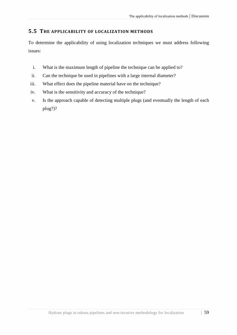
The applicability of localization methods | Discussion
Hydrate plugs in subsea pipelines and non-invasive methodology for localization | 59
5.5 THE APPLICABILITY OF LOCALIZATION METHODS To determine the applicability of using localization techniques we must address following
issues:
i. What is the maximum length of pipeline the technique can be applied to?
ii. Can the technique be used in pipelines with a large internal diameter?
iii. What effect does the pipeline material have on the technique?
iv. What is the sensitivity and accuracy of the technique?
v. Is the approach capable of detecting multiple plugs (and eventually the length of each
plug?)?

Discussion | What are the limitations for the existing methods?
60 | Hydrate plugs in subsea pipelines and non-invasive methodology for localization
5.6 WHAT ARE THE LIMITATIONS FOR THE EXISTING METHODS? A concise evaluation of the most proven methods introduced and discussed in section 4 is
presented in order to provide the reader with a summarily overview. Advantages and
limitations regarding the most proven methods are schematically listed; see Figure 5.6-1 to
Figure 5.6-6.
5.6.1 Pressure-Pulse Method
Figure 5.6-1 Evaluation Pressure-Pulse Method
5.6.2 Acoustic reflectometry
Figure 5.6-2 Evaluation acoustic reflectometry
Advantages
Accurate
Requires relatively low cost
instrumentation
Does not require interruption of
pipeline operation
Limitations
It only works with volumes of gas not
i excess of ~2%
Advantages
Accurate
Requires relatively low cost
instrumentation
Does not require interruption of
pipeline operation
Limitations
Only applicable for gas-lines
High level of noise through the pipe
from compression equipment and
pumps
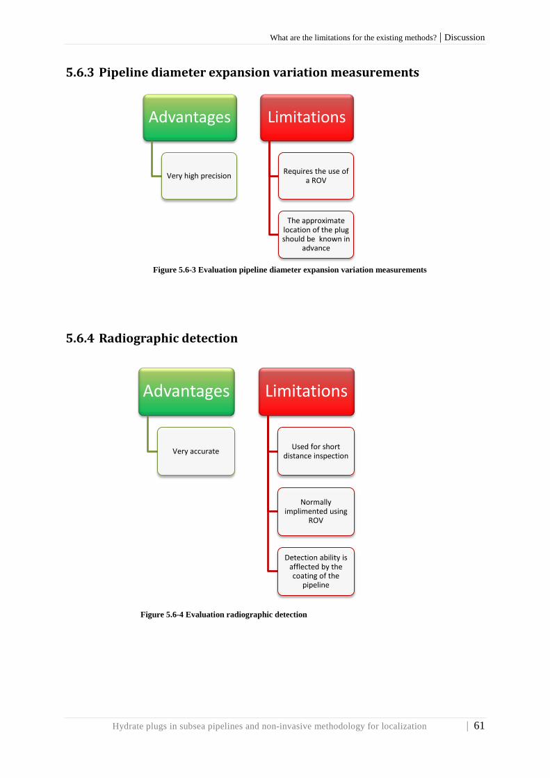
What are the limitations for the existing methods? | Discussion
Hydrate plugs in subsea pipelines and non-invasive methodology for localization | 61
5.6.3 Pipeline diameter expansion variation measurements
Figure 5.6-3 Evaluation pipeline diameter expansion variation measurements
5.6.4 Radiographic detection
Figure 5.6-4 Evaluation radiographic detection
Advantages
Very high precision
Limitations
Requires the use of a ROV
The approximate location of the plug should be known in
advance
Advantages
Very accurate
Limitations
Used for short distance inspection
Normally implimented using
ROV
Detection ability is afflected by the coating of the
pipeline

Discussion | What are the limitations for the existing methods?
62 | Hydrate plugs in subsea pipelines and non-invasive methodology for localization
5.6.5 Injection of inhibitor
Figure 5.6-5 Evaluation injection of inhibitor
5.6.6 Back pressurization
Figure 5.6-6 Evaluation back pressurization
Advantages
Requires relatively low cost
instrumentation
Limitations
Applicable when plug is assumed to
be close to platform
Require clean line
In most cases this methos is ineffective
Advantages
Requires relatively low cost
instrumentation
Limitations
Require clean line
Low degree of accuracy
challenging to conduct in
multiphase lines

What are the limitations for the existing methods? | Discussion
Hydrate plugs in subsea pipelines and non-invasive methodology for localization | 63
5.6.8 Subjective evaluation of the methods As the various methods for location of hydrate plugs is defined (chapter 4), and the
advantages and disadvantages of the different methods are presented (section 5.6), a
summarized, subjective evaluation is carried out, see Figure 5.6-7.
Figure 5.6-7 Subjective evaluation of methods In addition to the table below, Table 5.5-1, an explanation of Figure 5.6-7 is given on the next page.
Table 5.5-1
Explanation of Figure 5.5-5
Yellow bubbles Diagram axes
M1 Radiographic detection P(S) Probability of success
M2 Pipeline expansion (C|S) Quality of the system
M3 Acoustic reflectometry
Desirable
Undesirable
M4 Pressure-Pulse
M5 Injection of inhibitor
M6 Back pressurization

Discussion | What are the limitations for the existing methods?
64 | Hydrate plugs in subsea pipelines and non-invasive methodology for localization
The sizes of the yellow bubbles in the diagram characterizing the different methods represent
the cost- and time required to fully develop the method. The evaluation is made with respect
to the probability for the method to detect the plug, P(S), and the degree of accuracy given
that the plug is detected, (C|S). The information given in Figure 5.6-1 to Figure 5.6-4 is used
for the evaluation. A preferred method will in this diagram be represented by a relative small
bubble, placed up in the desirable area (green area).
What are the limitations for the existing methods? | Conclusion
Hydrate plugs in subsea pipelines and non-invasive methodology for localization | 65
6 CONCLUSION The current understanding of the mechanisms for hydrate formations, agglomerations and
plugging of an offshore pipeline are presented. A review of existing detection methods for
localization is identified and subjective evaluations are carried out. The industries need for
innovative solutions have been highly focused. Various non-invasive methods for localization
of hydrate plugs are defined and a subjective evaluation is carried out. The Pressure-Pulse
method is considered to be the most preferred localization technique, but still it has
limitations which require further development.
Applicability and efficiency of remediation techniques depend on plug location. Limited
accessibility for subsea plugs drives the motivation for a non-invasive methodology. More
efficient and accurate localization methods are highly needed. Further improvement potentials
are addressed in the concluding part, chapter 7.

Technology for the future | The industries need for innovative solutions
66 | Hydrate plugs in subsea pipelines and non-invasive methodology for localization
7 TECHNOLOGY FOR THE FUTURE 7.1 THE INDUSTRIES NEED FOR INNOVATIVE SOLUTIONS
Hydrate plugging is still a major flow assurance challenge. There is a need to deal with
hydrate plugs as long as there is oil and gas production. The applicability and efficiency of
remediation methods depend on plug location, and novel techniques for subsea hydrate plug
localization and remediation are greatly needed. Better hydrate remediation methods allow
less conservative hydrate control measures, which means less chemical usage and improved
field economy [86].
Some consequences of the new field development trends:
i. Greater water depths where the sea water is cold.
ii. Longer pipelines.
iii. Sub-zero ambient temperatures.
iv. Multiple tie-ins, sharing of risers.
These points may increase hydrate plugging probability and my makes it more difficult and
expensive to remove plugs. It is relatively easy to detect hydrate plugs at topside (for non-
insulated pipes). The limited accessibility to subsea plugs are precisely the big main
difference. The steps to be taken in remediating a subsea blockage are to locate, identify and
remove the obstruction. The accurate evaluation of the blockage location is a fundamental
part of this remediation process [1].
There is no single indicator that gives the best warning of hydrate formation, but pressure
drop is the most common indicator [29]. “There’s never been a better time for good ideas”
[86].
Real-time monitoring, fiber optic sensors (fiber optic cable); acoustic- or/and temperature
sensing are interesting methods. Eventually one could monitor the outside temperature of the
pipe.

Interdisciplinary technology adoption | Technology for the future
Hydrate plugs in subsea pipelines and non-invasive methodology for localization | 67
7.2 INTERDISCIPLINARY TECHNOLOGY ADOPTION
Research in the pharmaceutical industry is highly respected. In the attempt to draw
correlations between technologies applied in other industries, an interdisciplinary
investigation is carried out. Remediation techniques of kidney stones have been found to be
an interesting comparison with hydrate plugs. The similarity is remarkable, despite large
difference in size.
Lithotripsy – derived form the Greek word meaning “stone crushing”, is an effective
remediation method for eliminating kidney stones. It uses high-energy shock or sound waves
in order to crush dense calculi14 into smaller pieces that the pass naturally with urine. There
exists various techniques to pulverize those stones, but the most common is shockwave
lithotripsy where a high-energy impulse is focused on the kidney stone. Optional, sound
waves are guided by X-ray or ultrasound [93].
Figure 7.2-1 Multipurpose Supply AUV [98]
Figure 7.2-2 Inspection and communication AUV [98]
To adopt this technology to the oil and gas industry, it should be further developed in order to
fulfill the technological requirements for subsea operations. The above illustrations,
respectively Figure 7.2-1 and Figure 7.2-2 which represents innovative solutions for
autonomous subsea systems developed by FMC Technologies [98]. It would be interesting to
make further studies on the ability to equip similar concepts with shock wave- or sound wave
technology in order to crush hydrate plugs.
14 Mineral deposits that can form a blockage in the urinary system

Technology for the future | Optoelectronic technologies for the oil and gas industry
68 | Hydrate plugs in subsea pipelines and non-invasive methodology for localization
7.3 OPTOELECTRONIC TECHNOLOGIES FOR THE OIL AND GAS INDUSTRY
A novel optic sensing technique for measuring the distribution of droplets sizes in emulsions
(Figure 7.3-1) is a new technology in development which is found very interesting for the oil
and gas industry. The immediate idea created is the ability to monitor the hydrate shell growth
(section 3.5.3) and the possibility to record the hydrate agglomeration (section 3.5.3) in
subsea pipelines. This technology is able to measure size distribution, concentration and speed
of particles in pipeline flow [97].
Figure 7.3-1 Obscuration sensor [97]
Figure 7.3-1 show the world’s first “in-line” particle size concentration meter. A light field is
projected into the extended particle flow within which it defines a virtual volume sensitive to
particle transit. The particle size and velocity is determined from the resultant obscuration
signal detected as a particle passes through this virtual sensing volume [97].
With the potential of monitoring the two critical stages in the formation of a plug, hydrate
shell growth and the agglomeration of the hydrate particles in the flow, which is the limiting
factors for plug formation, one may at an early stage be able to detect the location of a plug
formation. If there at a stage of time will be possible to detect the presence of hydrate
particles in the flow it may be easier to, at the right moment, inject anti-agglomerants to
prevent agglomeration or depressurize to step out of the hydrate formation zone. This is
clearly a desirable feature that can make it possible to avoid a plug formed.

Tracerco’S discovery | Technology for the future
Hydrate plugs in subsea pipelines and non-invasive methodology for localization | 69
7.4 TRACERCO’S DISCOVERY
The British Company Tracerco launches the world’s first underwater scanner (Figure 7.4-1)
for inspection and flow assurance of coated unpiggable subsea pipelines. The pipeline
integrity can be assessed form the outside of the pipeline even through all kinds of insulation
and coating material [100]. The inspection device, called Discovery, can provide high
resolution images of pipeline contents and wall thinning from the outside. The device works
like a CT scanner known from hospitals. It is installed on the pipeline and provides a 360º
gamma ray scan in real time [99].
Basically, the tool was developed in order to detect the formation of hydrates in unpiggable
pipelines and in cases where the oil companies will not allow pigging in fear that the pig gets
stuck. “Inspection of subsea pipelines is often a challenge where pigging is not an option or is
deemed too risky. Discovery is a totally non-invasive device that provides asset integrity and
flow assurance information quickly and accurately” [101]. The inspection can be performed
without stop in production, which means big savings for the industry.
Figure 7.4-1 Tracerco's Discovery [102]
By being able to inspect the pipeline with high resolution pictures, will provide a lot of
detailed information about any restrictions in order to implement remedial actions in a more
efficient manner.

Technology for the future | Summary: technology for the future
70 | Hydrate plugs in subsea pipelines and non-invasive methodology for localization
The tool will be developed to perform operations in ultra-deep-waters, down to 3000 meters.
In order to operate inspection with Discovery, a surface vessel and an ROV are required for
connection to electricity, hydraulics and communications to the surface. The tool is expected
to be ready in 2014 and will be applicable to 6- 16 inch pipelines. Another version of
Discovery will be applicable for 16- 28 inch pipes and is designed for water depths down to
1000 meters [99].
The applicability using such a non-invasive inspection device have a huge potential to address
one of the major issues for hydrate plug identification mentioned in section 5.5; “is the
approach capable of detecting multiple plugs, and eventually the length of each plug?” By
being able to detect multiple plugs, the plug remediation measures will in a greater extent be
able to address the safety considerations (Safety first, section 2.2).
Such techniques are likely to meet time-consuming challenges in areas where the pipeline is
buried. In addition, it is costly to have both a surface vessel and an ROV operative during the
entire operation. Nevertheless, this is a product that arouses much attention among the oil
companies, among others Statoil, which has been involved in the technology development of
Discovery for being the first operator to utilize the device.
7.5 SUMMARY: TECHNOLOGY FOR THE FUTURE
An interdisciplinary investigation has been conducted in the attempt to adopt an existing
technology. A research within the pharmaceutical industry made us conscious of the sound-
and shock wave treatment for remediation of kidney stones. This is the most interesting
discovery that has been made in the quest for an innovative remediation method for hydrate
plugs. It would be interesting to make further studies on the ability to equip similar concepts
with shock wave- or sound wave technology in order to crush hydrate plugs.

| References
Hydrate plugs in subsea pipelines and non-invasive methodology for localization | 71
8 REFERENCES
[1] Wang X., Lennox B., Short G., (2010), “Operational Experience Using Acoustic
Reflectometry, to Detect Blockages in Gas Pipelines”, SPE 138045, Proceedings of
the Abu Dhabi International Petroleum Exhibition & Conference, 1st- 4th November,
2010, Abu Dhabi.
[2] Zolotukhin, A. “Economics and geopolitics global energy processes”, Lecture at BI,
January 14th, 2012, Oslo, Norway.
[3] Gudmestad, O. T., Zolotukhin A. B., Jarlsby E. T., “Petroleum Resources with
emphasis on offshore fields”, Published by WIT Press, 2010.
[4] SPT Group. http://www.sptgroup.com/en/Resources/News-Archive/SPT-Group-
acquires-Neotec-1/ accessed 4th March, 2013.
[5] Valmot O. R, «Fase to for flerfasestrøm», Teknisk Ukeblad, Published 18th March,
2013, Norway. Pp. 30-31.
[6] Bello O., Virani N., Oyadiji S. O., “Identification of blockages in a pipe using modal
analysis”, Proceedings of the ASME 2011 International Design Engineering Technical
Conferences & Computers and Information in Engineering Conference –IDETC/CIE
2011, August 28th- 31st. Washington, DC, USA.
[7] Wang X., Lennox B., Short G., Turner J., Lewis K., Ding Z., Dawson K., Lewis C.,
“Detecting blockages and valve status in natural gas pipelines”, Proceedings of the 8th
Internatinal Pipeline Conference – IPC2012, September 27-October 1st, 2010, Calgary,
Canada.
[8] Abney L., Kalman M., Hoogerhuis J., “Flow remediation solutions for pipelines”,
OTC 15258, Proceedings of the Offshore Technology Conference, May 5th- 8th, 2003,
Houston, Texas, USA.
[9] Odland J. (2012), “Subsea production systems”, MOK120 Offshore Field
Development, Department of Mechanical and Structural Engineering and Material
Science, University of Stavanger.
[10] Andrej A., Kaczmarski, Lorimer S. E., “Emergence of Flow Assurance as a
Technical Discipline Specific to Deepwater: Technical Challenges and Integration into

References |
72 | Hydrate plugs in subsea pipelines and non-invasive methodology for localization
Subsea Systems Engineering”, OTC 13123, Proceedings of Offshore Technology
Conference, 30 April 3rd May, 2001, Houston, Texas, USA.
[11] Eke E. A., “Investigation of Electrical Techniques to Locate Blockages in
Hydrocarbon Pipelines”, 2012, Master Thesis, University of Aberdeen.
[12] Macdonald K.A., Cosham A., Alexander C.R, Hopkins P., “Assessing mechanical
damage in offshore pipelines- Two case studies”, Engineering Failure Analysis 14
(2007) 1667-1679, December 21st, 2006.
[13] Cosham A., Hopkins P., “The Effect of Dents in Pipelines – Guidance in the Pipeline
Defect Assessment Manual”, Proceedings of ICPVT-10, July 7th- 10th, 2003, Vienna,
Austria.
[14] Wending L., Jing G., Xiaofang L., Jiankui Z., Yaorong F., Da Y., “A study of
hydrate plug formation in a subsea natural gas pipelines using a novel high-pressure
flow loop”, Chin University of Petroleum (Beijing) and Springer-Verlag Berlin
Heidelberg, 2013.
[15] Atilhan M., Aparicio S., Benyahia F., Deniz E., “Natural Gas Hydrates“, chapter 7 of
“Advances in Natural Gas Technology” plblished by InTech, April 11th, 2012.
[16] Guo D. B., Song D. B., Chacko J., Ghalambor D. A., “Offshore Pipelines”, Gulf
Professional Publishing, 2005.
[17] Makogon Y. F., Dunlap W. A., Holditch S. A., “Ocean methane hydrate
development: Reservoir character and extraction”, OTC 8300, Offshore Technology
Conference, 5th- 8th May, 1997, Texas, USA.
[18] Notz P. K., Bumgardner S. B., Todd J. L., “Application of Kinetic Inhibitor to Gas
Hydrate Problems”, SPE 30913, Paper peer approved July, 1996, proceedings of
Offshore Technology Conference, SPE Production and Facilities 1st- 4th May, 1995,
Houston, USA, pp. 256-260.
[19] Kelland M. A., Svartaas T. M., Dybvik L., “Studies on New Gas Hydrate Inhibitors”,
SPE 30420, Proceedings of SPE Offshore Europe Conference in Aberdeen, 5th- 8th
September, 1995
[20] Baillie C., Wichert E., “Oil and Gas Journal 85”, published in 1987, pp. 37-39
[21] Dincer I., “Refrigeration systems and applications”. John Wiley & Sons, Second
Edition, 2012, pp. 169-170.
[22] Xu Y., Yang X., Ding J., Ye G., «Natural Gas Industry 24», published 2004, pp. 135-
138

| References
Hydrate plugs in subsea pipelines and non-invasive methodology for localization | 73
[23] Prof. Khaydina M., “Unconventional hydrocarbon resources”, Lecture at Gubkin
Russian State University of Oil and Gas, Spring 2012, Moscow, Russia.
[24] Uchida T., Takeya S., Wilson L. D., Tulk C. A., Ripmeester J. A., Nagao J.,
Ebinuma T., Narita H., “Measurement of physical properties of gas hydrates in in situ
observations of formation and decomposition processes via Raman spectroscopy and
x-ray diffraction”, Can. J. Phys. Vol. 81, 2003, pp. 351-357.
[25] Zhu T., McGrail B. P., Kulkarni A. S., White M. D., Phale H., Ogbe D.,
“Development of a Thermodynamic Model and Reservoir Simulator for the CH4, CO2
and CH4-CO” Gas Hydrate System”, SPE 93976, Proceedings of SPE Western
Regional Meeting, 30th March-1st April, 2005, CA, USA.
[26] Mohammadi A. H., Tohidi B., “Gas Hydrates and Deepwater Operation: Predicting
the Hydrate- Free Zone”, SPE 99427, Proceedings of SPE Europe/EAGE Annual
Conference and Exhibition, 12th- 15th June, 2008, Vienna, Austria.
[27] Zuo Y. -X., Stenby E. H., «Prediction of Gas Hydrate Formation Conditions an
Aqueous Solutions of Single and Mixed Electrolytes», SPE Journal, Volume 2,
December, 1997.
[28] Canadian Association of Petroleum Producers, “Guideline for Prevention and Safe
Handling of Hydrates”, Updated version, 2007.
[29] Chandraguothan B., Nounchi G. B., “Detection and dealing with hydrate formation”,
Publiched by DigitlRefining, GAS 2010, April, 2010
[30] Jacobsen, L. M., “Traverserende gamma”, Sintef technology, Illustrations published
in Teknisk Ukeblad, Published 18th March, 2013, Norway. Pp. 31.
[31] SINTEF “1983: Seven- league steps on the seabed” Published at Internet;
http://www.sintef.no/home/Press-Room/Timeline/1983-Seven-league-steps-on-the-
seabed/ March 27, 2012, accessed 29th April, 2013.
[32] SPT Group, “OLGA® Simulation services”, brochure downloaded from:
http://www.sptgroup.com/upload/documents/Brochures/multiphase_services08.pdt ,
27th April, 2013.
[33] Bendiksen K. H., Malnes D., Moe R., Nuland S., “The Dynamic Two-Fluid Model
OLGA: Theory and Application”, SPE 19451, Published by Society of Petroleum
Engineers, SPE Production Engineering, May 1991. Pp 171 -180.
[34] Svartås T. M., 2013, personal statement regarding existing technologies, April 29th,
2013, University of Stavanger, Norway.

References |
74 | Hydrate plugs in subsea pipelines and non-invasive methodology for localization
[35] Sloan Jr. E.D., (2000), “Hydrate Engineering”, monograph volume 21, First edition,
SPE Henry L. Doherty Series, Society of Petroleum Engineers Inc., 2000, Richardson,
Texas, USA.
[36] Sloan, E.D. and Koh C.A., (2008), “Clathrate Hydrates of Natural Gases”, third
edition, Taylor & Francis Group, 2008.
[37] Sloan, E.D., (2004) “Introductory overview: Hydrate knowledge development”,
Proceedings of American Mineralogist, volume 89, pages 1155- 1161, 2004.
[38] Turner, D.J., (2005) “Clathrate Hydrate Formation in Water-in-Oil Dispersions”,
Ph.D. Thesis, Colorado School of Mines, Golden, CO, USA.
[39] Lingelem, M.N., Mejeed A.I., Stange E., (1994), «Industrial Experience in
Evaluation of Hydrate Formation, Inhibition, and Dissociation in Pipeline Design and
Operation», Proceedings of The International Conference on Natural Gas Hydrates,
1994,Volume 715, pp. 75-93.
[40] Davies, R.d., Boxall J.A., Dieker L.E., Sum A.K., Koh C.A., Sloan E.D., Creek J.L.,
Xu Z.G., (2009) “Improved Predictions of Hydrate Plug Formation in Oil-Dominated
Flowlines” Offshore Technology Conference, 4-7 May, 2009, Texas, USA.
[41] SPT Group, webpage: http://www.sptgroup.com/en/products/olga/ , accessed 3rd
May, 2013.
[42] Taylor, C.J. (2006), “Adhesion Force Between Hydrate Particles and Macroscopic
Investigation of Hydrate Film Growth at the Hydrocarbon/Water Interface”, M.Sc.
Thesis, Colorado School of Mines, Golden, CO, USA
[43] Mehta, A.P., Herbert P.B., Cadena E.R., Weatherman J.P., (2003), “ Fulfilling the
Promise of Low-Dosage Hydrate Inhibitors: Journey From Academic Curiosity to
Successful Field Implementation”, SPE 81927, Society of Petroleum Engineers,
Production & Facilities, Proceedings of Offshore Technology Conference , 6th- 9th
May, 2002, Houston, USA.
[44] Wolden, M., Lund A., Oza N., Makogon T., Argo C.B., Larsen R., (2005), «Cold
Flow Black Oil Slurry Transport of Suspended Hydrate and Wax Solids», Proceedings
of the Fifth International Conference on Gas Hydrates, Volume 4, 13th- 16th June,
Trondheim, Norway. Pp. 1101- 1106.
[45] Toscano, S., (2007), “Supercharged methanol cuts hydrates”, Baker Petrolite,
website: http://www.epmag.com/EP-Magazine/archibe/Supercharged-methanol-cuts-
hydrates_350 , accessed 6th May 2013.

| References
Hydrate plugs in subsea pipelines and non-invasive methodology for localization | 75
[46] Chandragupthan, B., Nouchhi G.B., (2009), “An Overveiw on Gas Hydrate Early
Warning System, Detection, Prevention & Control”, Proceedings and Fundamentals
Manual, Laurance Reid Gas Conditioning Conference (LRGCC) 2009, Norman,
Oklahoma, USA. Pp. 107-129.
[47] Lahlou, M.Z. (2003), “Water Hammer”, A National Drinking Water Clearinghouse
Fact Sheet, Tech Brief, West Virginia University, USA.
[48] Celius, H.K., Korsan K., (1999), “The PressurePulse Method for Multi-Phase
Metering”, Proceedings of IBC conference “Field Applications & New Technologies
for multiphase metering”, Aberdeen, February, 1999.
[49] Gudmundsson , J.S., Celius H.K., (1999), “Gas-Liquid Metering Using Pressure-
Pulse Technology”, SPE 56584, Proceeding of SPE Annual Technical Conference
Exhibition, Houston, Texas, 3rd-6th October, 1999.
[50] Gudmundsson, J.S., Durgut I., Rønnevig J., Korsan K., Celius H.K., (2002),
«Pressure Pulse Analysis of Flow in Tubing and Casing of Gas Lifting Wells»,
Preceedings of ASME/API Gas Lift Workshop, February 5th -6th, 2002, Houston,
Texas, USA
[51] Palermo, T., Mussumeci A., Leporcher E., (2004), “Could Hydrate Plugging Be
Avoided Because of Surfactant Properties of the Crude and Appropriate Flow
Conditions?”, OTC 16681, Proceeding of the Offshore Technology Conference 3rd-6th
May, 2004, Houston, Texas, USA.
[52] Hatton, G.J., Kruka V.R., (2002), “Hydrate Blockage Formation-Analysis of Werner
Bolley Field Test Data”, Deepstar CTR 5209-1
[53] Lanan, G.A., Cowin T.G., Johnston D.K., (2011), “Alaskan Beaufort Sea Pipeline
Design, Installation and Operation”, OTC 22110, Proceedings of Arctic Technology
Conference 7th- 9th February, 2011, Houston, Texas, USA.
[54] Lanan, G.A., Ennis J.O., Egger P.S., Yockey K.E., (2001), “Northstar Offshore
Arctic Pipeline Design and Construction”, OTC 13133, Proceedings of Offshore
Technology Conference 30th April- 3rd May, 2001, Houston, Texas, USA.
[55] Roth, R.F., Voight R., DeGeer D., (2012), “Direct Electrical Heating (DEH)
Provides New Opportunities for Arctic Pipelines”, OTC 23732, Proceedings of the
Arctic Technology Conference 3rd- 5th December, 2012, Houston, Texas, USA.
[56] Løset, S., Høyland K.V., (2012), “Ice Physics and Mechanics”, compendium for AT-
327, UNIS, Svalbard, autumn 2012.
[57] Jeffery, G.A., McMullan R.K., 1967, Prog. Inorg. Chem., 8, 43

References |
76 | Hydrate plugs in subsea pipelines and non-invasive methodology for localization
[58] Davidson, D.W., 1973, “Water: A Comprehensive Treatise”, Plenum, New York
[59] Jeffery, G.A., 1984, “Inclusion Compounds”, (Atwood, J.L. Davies, J.E.D.,
MacNichol, D.D., eds.) Academic Press, pp 135
[60] Davidson, D.W., Ripmeester J.A., 1984, “Inclusion Compounds”, (Atwood, J.L.
Davies, J.E.D., MacNichol, D.D., eds.) Academic Press, 3, Chapter 3, 69
[61] McMullan, R.K., Jeffrey G.A., 1965, “Journal of Chemical Physics”., 42, 2725
[62] Mak, C.W., McMullan R.K., 1965, “Journal of Chemical Physics”., 42, 2732
[63] Wikipedia contributors, 2013, “Polyhedron”, Wikipedia, The Free Encyclopedia, 30
March, 2013, Page visited 23rd May, 2013.
[64] Von Stackelberg, M., 1949, “Naturweiss”, 36, 359
[65] Von Stackelberg, M., 1954, “Elektochem.”, 58, 104
[66] Von Stackelberg, M., 1956, “Rec. Trav. Chim. Pays-Bas”, 75, 902
[67] Von Stackelberg, M., Müller H.R., 1951, “Naturweiss”, 38, 456
[68] Von Stackelberg, M., Müller H.R., 1951, “Journal of Chemical Physics., 19, 1319
[69] Claussen, W.E., 1951, “Suggested Structures of Water in Inert Gas Hydrate”,
Journal of Chemical Physics, 19, 662
[70] Claussen, W.E., 1951, “Journal of Chemical Physics”, 19, 1425
[71] Pauling, L., Marsh R.E., 1952, “Proc. Natal. Acad. Sci. USA, 38, 112
[72] Ripmeister J.A., Tse J.S., Ratcliffe C.I., Powell B.M.,1987, “Nature”, 325, 135
[73] Jeffrey, G.A., 1984, “Inclusion Compounds, (Atwood J.L. Davies J.E.D.,
MacNichol, D.D., eds.) Academic Press, pp 135
[74] Rodger, P.M., 1990, “Stability of Gas Hydrates”, Journal of Chemical physics, 94,
pp. 6080-6089
[75] Rodger, P.M., 1990, “Mechanisms for Stabilizing Water Clathrates”, Molecular
Simulation, 5, pp. 315-328
[76] Chakoumakos, B.C., Rawn, C.J., Rondinone, A.J., Stern, L.A., Circone, S., Kirby,
S.H., Ishii, Y., Jones, C.Y., Toby, B.H., 2003, “𝐶𝑂2hydrate: Synthesis, composition,
dissociation behavior, and comparison to structure I 𝐶𝐻4 hydrate”, Journal of
Chemical Physics, 81, 183
[77] Udachin, K.A.,Ratcliffe, C.I., Enright, G.D., Ripmeester, J.A., 1997, “Structure H
hydrate: A single crystal diffraction study of 2,2-dimethylpentane 5(Xe,H2S).
34H2O”. Supramolecular Chemestry, Volume 8, Pp. 173-176
[78] Sloan, E.D. Jr., 2003, “Fundamental principles and applications of natural gas
hydrates”, Nature, 20th November, 2003, Vol. 426, pp. 353-363

| References
Hydrate plugs in subsea pipelines and non-invasive methodology for localization | 77
[79] Huo, Z., Jager, M.D., Miller, K.T., Sloan, E.D. Jr., 2002, «Ethylene oxide hydrate
non-stoichiometry: measurements and implications», Chemical Engineering Science,
Vol. 57, pp. 705-713
[80] Glew, D.N., Rath, N.S., 1966, “Variable Composition of the Chlorine and Ethylene
Oxide Clathrate Hydrates”, Journal of Chemical Physics, Vol. 44, pp. 1710-1711
[81] Fox, J.S., 1989, “Transient Flow in Pipes, Open Channels and Sewers”, Ellis
Horwood Limited.
[82] Thorley, A.R.D., 1991, “Fluid Transients in Pipeline Systems”, Second Edition, The
American Society of Mechanical Engineers, New York, USA
[83] Falk, K., Hervieu, E., Gudmundsson, J.S., 1991, “Pressure Pulse and Void Fraction
Propagation in Two Phase Flow: Experiments for Different Flow Regimes”,
Proceedings of the Second International Symposium on Two-Phase Floe in Modeling
and Experiments, pp. 8, 23rd-26th May, Pisa, Italy
[84] Dong, L., Gudmundsson, J.S., 1993, “Model of sound speed in Multiphase
Mixtures”, Proceedings of the Third Lerkendal Petroleum Engineering Workshop,
Norwegian Institute of Science and Technology, Trondheim, Norway. Pp. 19-29
[85] Gudmundsson, J.S., Dong, L., 1993, “Model for Speed Sound in Multiphase
Mixtures”.
[86] Li, X., 2012, “Hydrate plugs – Still a Major Flow Assurance Challenge”, Flow
Assurance Lecture at NTNU, 16th May, 2012, Trondheim, Norway
[87] Odland J. (2012), “Transportatin and marketing of oil and gas”, MOK120 Offshore
Field Development, Department of Mechanical and Structural Engineering and
Material Science, University of Stavanger
[88] Kuchpil, C., Marques, L.C.C., Goncalves, M.A.L., Ferreira, A.C.P., Albernaz, R.S.,
Camerini, C.S., 2002,”Blockage remediation in deep water pipelines” Proceedings of
the 4th International Pipeline Conference, IPC, Volume B, pp. 2065- 2070, 30th
September- 3rd October, 2002, Calgary, Canada
[89] Chen, X., Tsang, Y., Zhang, H.Q., Chen, T.X., 2007, «Pressure- Wave Propagation
Technique for Blockage Detection in Subsea Flowlines”, SPE 110570, Proceedings of
SPE Annual Technical conference and Exhibition, 11th- 14th November, 2007,
Anaheim, California, USA.
[90] Papadopoulou, K.A., Shamout, M.N., Lennnox, B., Mackay, D., Taylor, A.R.,
Turner, J.T., Wang, X., 2008, “An evaluation of acoustic reflectometry for leakage

References |
78 | Hydrate plugs in subsea pipelines and non-invasive methodology for localization
and blockage detection”, Proceedings of Institute of Mechanical Engineers 2007,
Volume 222, Part C, pp. 959- 966.
[91] International Energy Agency (IEA), 2008, “World Energy Outlook” © OECD/IEA,
table 2.1, pp. 78.
[92] Heskestad, K.L., 2004, “Deposits Detection Using Pressur Pulse Technology”,
Ormen Lange Pipelines Case Study Using Process Simulation Tools, December 2004,
NTNU, Trondheim, Norway.
[93] Miller, N.J., Lingeman, J.E., 2007, «Management of kidney stones», Proceedings of
British Medical Journal, 3rd March, 2007, Volume 334, pp. 468- 472.
[94] Kongsberg Oil & Gas Technologies, 2010, “Flow Assurance for 21st Century Oil &
Gas Production”, Brochure, 2010.
[95] Heriot Watt Institute of Petroleum Engineering, 2013, “A large hydrate plug
formation in a subsea hydrocarbon pipeline”, Petrobras, Website:
http://www.pet.hw.ac.uk/research/hydrate/hydrates_why.cfm, accessed 21st June 2013.
[96] Ginsburg, G.D., Soloviev, V.A., 1998, “Submarine gas hydrates”,
VNIIOkeangeologia, St. Petersburg
[97] Metcalfe, F., 2013, “A Novel Optical Sensing Technique for Measuring the
Distribution of Droplet Sizes in Emulsions”, Presentation, 6th June 2013, Aberdeen,
Scotland.
[98] Thorkildsen, B., 2013, “FMC Summer Trainee Technology Program – Innovative
solutions for autonomous subsea systems”, Presentation at NFA Conference, March
2013, Sola, Stavanger, Norway.
[99] Stensvold, T., 2013, “Ser gjennom isolerte rør”, article published in Teknisk
Ukeblad, 13th June, 2013. Pp. 50-51
[100] Offshore Magazine, “Tracerco introduces first subsea pipeline CT scanner”,
website: http://www.offshore-mag.com/articles/2013/06/tracerco-introduces-first-
subsea-pipeline-ct-scanner.html, accessed 29th June, 2013.
[101] Robins, L., 2013, “Tracerco introduces first pipeline CT scanner”, personal
statement Head of Subsea Services at Tracerco, published 18th June, 2013.
[102] Tracerco Discovery, 2013, “The world’s first subsea CT scanner”, animation:
http://www.youtube.com/watch?v=0F7lGo9aFlk, accessed 29th June, 2013.
[103] Abney, L.J., Mackay, N., McGillivray, B., Gudmestad, O.T., 2013, discussion
about requirements for detection and location methods, 19th May, 2013, Halliburton,
Tananger, Norway.

| Annex A
Hydrate plugs in subsea pipelines and non-invasive methodology for localization | 1
9 ANNEX A
This appendix represents a summary of rules of thumbs based on experiences and is intended
as a guideline for engineers dealing with hydrates. These rules of thumb are not supposed to
be interpreted as absolute verities.
Rule-of-Thumb 1 The first rule of thumb describes the conditions for hydrate formation at
deep-ocean-bottom where it is assumed a temperature of 39 F (about 4 ºC). This temperature
is normally the lowest temperature on the deep ocean bottom. At this temperature, hydrates
will form if free water is available and the pressure is greater than 166 psi [35].
Rule-of-Thumb 2 Attempts to blow the plug out of the pipeline by increasing the pressure
differential, results in more hydrate formation because higher pressures place the system
farther into the hydrate-formation region. When a hydrate blockage is experienced in an
offshore system, for safety reasons, the first step is to inject inhibitor into the platform in an
attempt to determine the plug distance from the platform [35].
Rule-of-Thumb 3 Use of anti-agglomerants requires a substantial oil-condensate phase. The
maximum water/oil ratio (volume basis) for the use of anti-agglomerants is 40:60 [35].
Rule-of-Thumb 4 Hydrate plugs occur due to abnormal operating conditions which leads
into the hydrate formation region, such as ell tests with water, loss of inhibitor injection,
dehydrator malfunction, startup, and shut-in [35].
Rule-of-Thumb 5 In water-gas systems, hydrates tend to build up on the pipe wall. In gas-
condensate or gas-oil systems, hydrates commonly form from free water accumulations as
agglomerate and bridge as plugs [35].
Rule-of-Thumb 6 Hydrate agglomeration cause a porous hydrate mass (typically > 50%)
which is permeable to gas flow. Such an open hydrate mass has the abnormal property of
transmitting pressure while being a substantial liquid-flow impediment. Hydrate plugs harden
to lower permeability over longer times [35].