information hiding in h.264 compressed video vardhan reddy mukku mav id: 1000989621 email:...
TRANSCRIPT

Information Hiding in H.264 Compressed Video
AN INTERIM PROJECT REPORT UNDER THE GUIDANCE OF DR K. R. RAO
COURSE: EE5359 – MULTIMEDIA PROCESSING, SPRING 2014
SUBMISSION Date: 04/02/14
SUBMITTED BY
VISHNU VARDHAN REDDY MUKKU
Mav ID: 1000989621
Email: [email protected]
DEPARTMENT OF ELECTRICAL ENGINEERING
UNIVERSITY OF TEXAS, ARLINGTON.

ACRONYMS:
AVC : Advanced Video Coding
AEU : Australian Education Union
BRI : Bit Rate Increase
CAVLC : Context-Adaptive Variable Length Coding
CABAC : Context-Adaptive Binary Arithmetic Coding
CB : Candidate Block
CU : Coding Unit
DCT : Discrete Cosine Transform
FMO : Flexible Macroblock Ordering
GOP : Group of Pictures
HB : Host Block
HBQ : Hidden Bit Quantity
ITU : International Telecommunication Union
ISO/IEC : International Organization for Standardization/International Electro technical Commission
JVT : Joint Video Team
LSB : Least Significant Bit
MB : Macro Block
MPM : Most Probable Mode
RDO : Rate Distortion Optimization
SAE : Sum of Absolute Error
SP Frame : Stored P Frame
SI Frame : Stored I Frame

TABLE OF CONTENTS
1. Abstract…………………………………………………………………………....4
2. H.264 video coding standard…………………………………………………...4
2.1. Introduction………………………………………………………………....4
2.2. Encoder and Decoder in H.264………………………………….………...4
3. Prediction in H.264……………………………………………………………...7
3.1. Macroblock prediction types………………………………………..……7
3.2. Intra Prediction………………………………………………………….….8
3.3. Intra Mode Decision…………………………………………………..……9
3.4. RDO (Rate Distortion Optimization)……………………………………11
4. Algorithm of Information hiding approach………………………….……..12
4.1. Embedding Conditions …………………………………………….…….12
4.2. Watermark Mapping Rules.………………………………………...…...13
5. Watermark embedding and extraction process…………………...……...15
5.1. Watermark embedding process…………………………………..…….15
5.2. Watermark detection process……………………………………..……15
6. Experimental Results………………………………………………………….17
7. References…………………………………………………………………..…..21

1. Abstract
An information hiding algorithm based on intra-prediction modes and matrix coding is proposed for
H.264/AVC video stream. It utilizes the block types and modes of intra-coded blocks to embed
watermark. Intra - 4 × 4 coded blocks (4×4-blocks) are divided into groups and two watermark bits are
mapped to every three 4×4-blocks by matrix coding to map between watermark bit and intra-prediction
modes. Since only the mode of an 4×4-block is changed for every two watermark bits, it can guarantee a
high PSNR and slight bitrate increase after watermark embedding. Moreover, embedding position
template is utilized to select candidate 4×4-blocks for watermark embedding, which further enhances the
security of watermark information. Experimental results on several test sequences demonstrate that the
proposed approach can realize blind extraction with real-time performance.
2. H.264 Video Coding Standard
2.1. Introduction:
H.264/Advanced Video Coding (AVC) [1] is video coding standard of the ITU-T Video Coding
Experts Group and the ISO/IEC Moving Picture Experts Group. The main goals of the H.264/AVC
standard were to enhance compression performance and provision of a network-friendly video
representation addressing conversational (video telephony) and non-conversational (storage, broadcast, or
streaming) applications [2].
2.2 Encoder and Decoder in H.264:
In comparison to the previous standards [3], H.264 incorporates various new features to further
improve video compression efficiency. Notably, these features include intra prediction in intra-frame,
multiple frames reference capability, quarter-pixel interpolation, deblocking filtering, and flexible
macroblock ordering (FMO). In general, H.264 divides the sequence of frames (i.e., images) into several
groups of pictures (GOPs). These frames are labeled as I (intra), P (predicted), and B (bi directionally
predicted) frames, depending on the order in which they appear.
Fig. 1: H.264 hybrid video encoder [4].
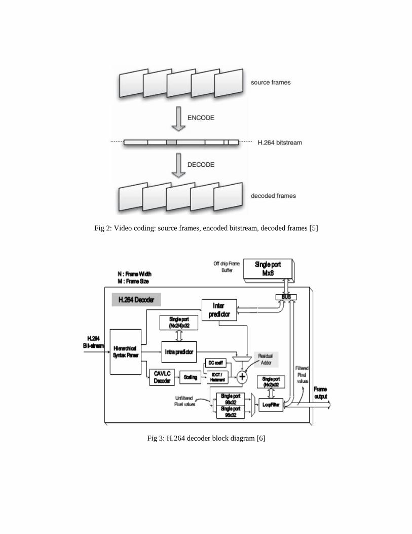
Fig 2: Video coding: source frames, encoded bitstream, decoded frames [5]
Fig 3: H.264 decoder block diagram [6]
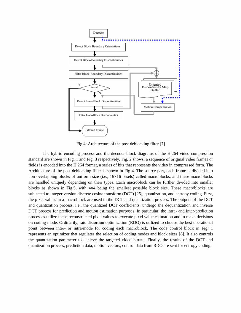
Fig 4: Architecture of the post deblocking filter [7]
The hybrid encoding process and the decoder block diagrams of the H.264 video compression
standard are shown in Fig. 1 and Fig. 3 respectively. Fig. 2 shows, a sequence of original video frames or
fields is encoded into the H.264 format, a series of bits that represents the video in compressed form. The
Architecture of the post deblocking filter is shown in Fig 4. The source part, each frame is divided into
non overlapping blocks of uniform size (i.e., 16×16 pixels) called macroblocks, and these macroblocks
are handled uniquely depending on their types. Each macroblock can be further divided into smaller
blocks as shown in Fig.5, with 4×4 being the smallest possible block size. These macroblocks are
subjected to integer version discrete cosine transform (DCT) [25], quantization, and entropy coding. First,
the pixel values in a macroblock are used in the DCT and quantization process. The outputs of the DCT
and quantization process, i.e., the quantized DCT coefficients, undergo the dequantization and inverse
DCT process for prediction and motion estimation purposes. In particular, the intra- and inter-prediction
processes utilize these reconstructed pixel values to execute pixel value estimation and to make decisions
on coding-mode. Ordinarily, rate distortion optimization (RDO) is utilized to choose the best operational
point between inter- or intra-mode for coding each macroblock. The code control block in Fig. 1
represents an optimizer that regulates the selection of coding modes and block sizes [8]. It also controls
the quantization parameter to achieve the targeted video bitrate. Finally, the results of the DCT and
quantization process, prediction data, motion vectors, control data from RDO are sent for entropy coding.

Fig 5: Block size type selection for intra- and inter-macroblock to embed information [4]
The output of entropy coding is a series of compressed video contents in the binary stream
preceded and/or inter-leaved with various predefined markers. Context based Adaptive Variable Length
Coding (CAVLC) [25] and Context based Adaptive Binary Arithmetic Coding (CABAC) [23] are the two
widely used entropy coding techniques. The combined bit stream is then transmitted and/or stored in
various media. HEVC is latest to H.264 and the special issues on HEVC [30] [31] [32] are presented in
several papers.
3. Prediction in H.264
3.1. Macroblock prediction types [9]
Fig.6 shows the prediction sources for three macroblocks. An I-Macroblock, a P-Macroblock and a B-
Macroblock. An I Macroblock (I MB) is predicted using intra prediction from neighboring samples in the
current frame. A P Macroblock (P MB) is predicted from samples in a previously-coded frame which may
be before or after the current picture in display order, i.e. a „past‟ or a „future‟ frame. Different rectangular
sections (partitions) in a P MB may be predicted from different reference frames.
Fig 6: Example of macroblock types and prediction sources [9]

Each partition in a B Macroblock (B MB) is predicted from samples in one or two previously-coded
frames, for example, one „past‟ and one „future‟ as shown in the figure 6.
One important aspect of digital watermarking is the capacity or amount of data that can be embedded into
a host signal. Most data-hiding techniques exploit perceptual masking to optimize capacity. Clearly, a
higher capacity is achieved considering the inherent properties of different media when applying
perceptual masking [18]. SP and SI [19] frames are the picture types used in H.264 for error-resilience
and random access.
3.2 INTRA PREDICTION
An intra (I) macroblock [9] is coded without referring to any data outside the current slice. I macroblocks
may occur in any slice type. Every macroblock in an I slice is an I macroblock. I macroblocks are coded
using intra prediction, i.e. prediction from previously-coded data in the same slice. For a typical block of
luma or chroma samples, there is a relatively high correlation between samples in the block and samples
that are immediately adjacent to the block. Intra prediction therefore uses samples from adjacent,
previously coded blocks to predict the values in the current block. In intra mode [16], a prediction block P
is formed based on previously encoded and reconstructed blocks and is subtracted from the current block
prior to encoding. For the luminance samples, P is formed for each 4×4 block or for a 16×16 macroblock.
In an intra macroblock, there are three choices of intra prediction block size for the luma component,
namely 16×16, 8×8 or 4×4. A single prediction block is generated for each chroma component. Each
prediction block is generated using one of a number of possible prediction modes.
The choice of intra prediction block size for the luma component, 16×16, 4×4 or 8×8 when
available, tends to be a trade-off between (i) prediction efficiency and (ii) cost of signaling the prediction
mode [9]. (a) Smaller blocks: A smaller prediction block size (4 ×4) tends to give a more accurate
prediction, i.e. the intra prediction for each block is a good match to the actual data in the block. This in
turn means a smaller coded residual, so that fewer bits are required to code the quantized transform
coefficients for the residual blocks. However, the choice of prediction for every 4×4 block must be
signaled to the decoder, which means that more bits tend to be required to code the prediction choices.
Intra prediction source samples for 4×4 or I8 block is shown in Fig 7.(b) Larger blocks: A larger
prediction block size (16 ×16) tends to give a less accurate prediction, hence more residual data, but fewer
bits are required to code the prediction choice itself. Intra prediction source samples for I16 block is
shown in Fig.8.
Fig 7: Intra prediction source samples, Fig 8: Intra prediction source samples,
4×4or8×8 luma blocks [9] chroma or 16×16 luma blocks [9]

3.3. INTRA MODE DECISION:
Intra prediction in H.264 exploits the spatial correlation between the adjacent macroblocks. In
JVT, the current macroblock is predicted by adjacent pixels in the upper and the left macroblocks
that are decoded earlier. Then, the residual between the current macroblock and its prediction is
transformed, quantized and entropy coded. Roughly speaking, the smaller the differences, the fewer the
coding bits are demanded for the current macroblock. To get a richer set of prediction patterns, H.264
offers 9 prediction modes for 4×4 luma blocks (as in the Fig 9) and 4 prediction modes for 16×16 luma
blocks. For the chrominance components, there are 4 prediction modes applied to the two 8×8 chroma
blocks (U and V). The encoder has to select the best combination of prediction modes for each
macroblock to obtain the optimal RD performance [10]. For intra-4 × 4 prediction, each mode has its own
prediction direction and the predicted pixels a–p are obtained from a weighted average of reference pixels
A–M. For instance, mode 2 is the dc prediction where all pixels are predicted by (A + B + C + D + I + J +
K + L)/8. Fig.10 shows an example to the 9 modes in 4×4 block prediction.
Fig 9: 4×4 intra prediction modes [11] in H.264
Table 1: Intra prediction modes in H.264 for 4×4 blocks [5]
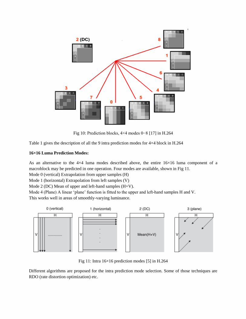
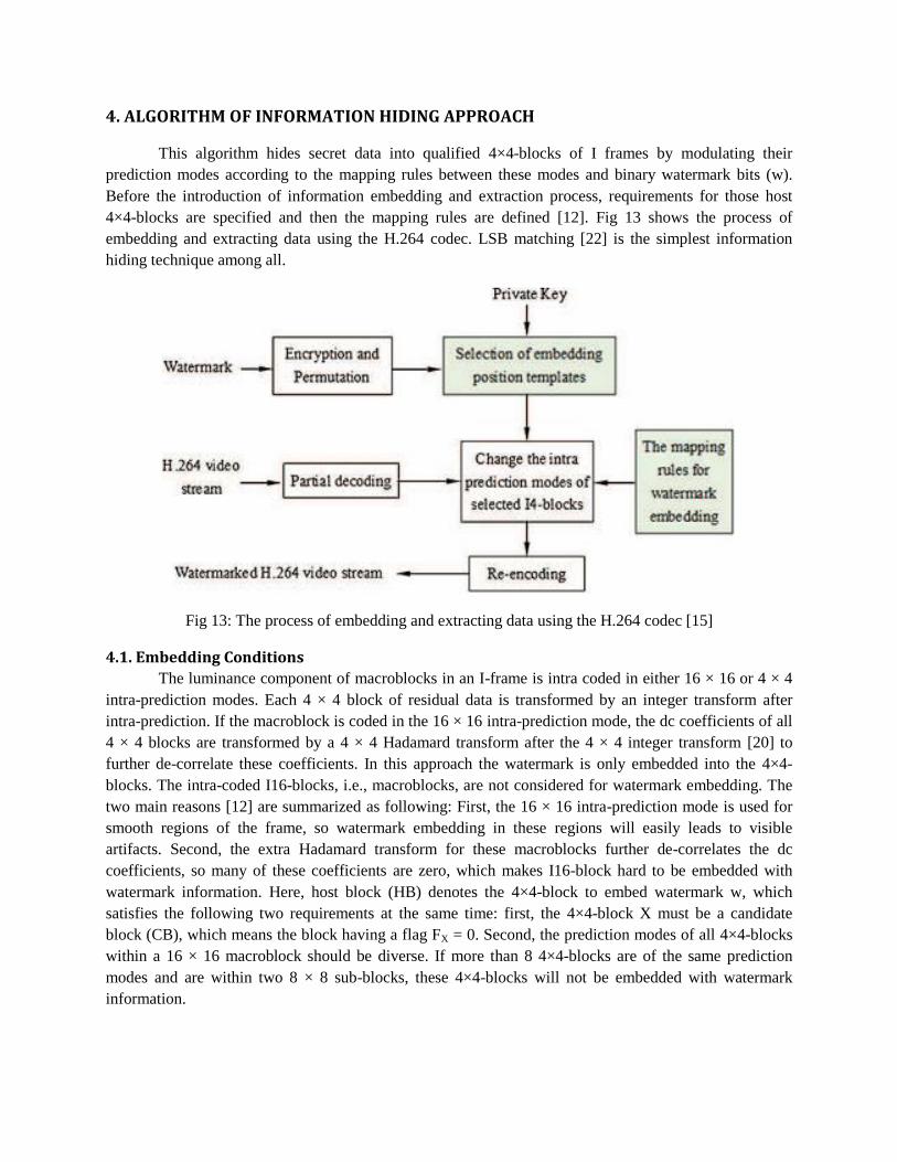
Fig 10: Prediction blocks, 4×4 modes 0−8 [17] in H.264
Table 1 gives the description of all the 9 intra prediction modes for 4×4 block in H.264
16×16 Luma Prediction Modes:
As an alternative to the 4×4 luma modes described above, the entire 16×16 luma component of a
macroblock may be predicted in one operation. Four modes are available, shown in Fig 11.
Mode 0 (vertical) Extrapolation from upper samples (H)
Mode 1 (horizontal) Extrapolation from left samples (V)
Mode 2 (DC) Mean of upper and left-hand samples (H+V).
Mode 4 (Plane) A linear „plane‟ function is fitted to the upper and left-hand samples H and V.
This works well in areas of smoothly-varying luminance.
Fig 11: Intra 16×16 prediction modes [5] in H.264
Different algorithms are proposed for the intra prediction mode selection. Some of those techniques are
RDO (rate distortion optimization) etc.

3.4. RDO (Rate Distortion Optimization):
The RDO method [12] searches, for each 4×4-block, the best mode with the metric of minimum
rate distortion cost, and then OPTX is adopted as the prediction mode of X, named MX. In addition to the
rich set of intra-prediction modes, the correlation of spatially adjacent blocks is also exploited by
H.264/AVC encoder to encode the prediction modes more efficiently. As illustrated in Fig 12, the most
probable mode MPMX for the current 4×4-block is computed based on the prediction modes of its top
block A and left block B, which are denoted as MA and MB, respectively, by MPMX = min{MA, MB}. The
encoder sends a flag (F) for each 4×4-block to indicate whether MPMX is adopted as MX by
F = 1; OPTX = MPMX
0; OPTX ≠ MPMX
Fig 12: 4×4-block X and its adjacent 4×4-blocks A and B [12] in H.264
If the flag is 1, MPMX is used and this time OPTX = MPMX ; Otherwise, another parameter REMX is sent
to indicate MX and then it satisfies the equation MX = OPTX by
REMX = OPTX ; OPTX < MPMX
OPTX – 1 ; OPTX > MPMX
In this way, only 8 values (0–7) of REMX are adequate to signal all possible modes of current 4×4-blocks.
Since intra-prediction is exploited to reduce spatial redundancy for compression purpose, the change of
intra-prediction modes will cause bitrate increase.
4. ALGORITHM OF INFORMATION HIDING APPROACH
This algorithm hides secret data into qualified 4×4-blocks of I frames by modulating their
prediction modes according to the mapping rules between these modes and binary watermark bits (w).
Before the introduction of information embedding and extraction process, requirements for those host
4×4-blocks are specified and then the mapping rules are defined [12]. Fig 13 shows the process of
embedding and extracting data using the H.264 codec. LSB matching [22] is the simplest information
hiding technique among all.
Fig 13: The process of embedding and extracting data using the H.264 codec [15]
4.1. Embedding Conditions
The luminance component of macroblocks in an I-frame is intra coded in either 16 × 16 or 4 × 4
intra-prediction modes. Each 4 × 4 block of residual data is transformed by an integer transform after
intra-prediction. If the macroblock is coded in the 16 × 16 intra-prediction mode, the dc coefficients of all
4 × 4 blocks are transformed by a 4 × 4 Hadamard transform after the 4 × 4 integer transform [20] to
further de-correlate these coefficients. In this approach the watermark is only embedded into the 4×4-
blocks. The intra-coded I16-blocks, i.e., macroblocks, are not considered for watermark embedding. The
two main reasons [12] are summarized as following: First, the 16 × 16 intra-prediction mode is used for
smooth regions of the frame, so watermark embedding in these regions will easily leads to visible
artifacts. Second, the extra Hadamard transform for these macroblocks further de-correlates the dc
coefficients, so many of these coefficients are zero, which makes I16-block hard to be embedded with
watermark information. Here, host block (HB) denotes the 4×4-block to embed watermark w, which
satisfies the following two requirements at the same time: first, the 4×4-block X must be a candidate
block (CB), which means the block having a flag FX = 0. Second, the prediction modes of all 4×4-blocks
within a 16 × 16 macroblock should be diverse. If more than 8 4×4-blocks are of the same prediction
modes and are within two 8 × 8 sub-blocks, these 4×4-blocks will not be embedded with watermark
information.

4.2. Watermark Mapping Rules
To decrease the bitrate increase and visual distortion by watermark embedding, the changes of intra-
prediction modes should be as less as possible. However, the minimum changes of intra prediction modes
still should be at the sacrifice of embedding capacity. In the work by Hu et al [13], the optimal mode for
4×4-block is changed to sup-optimal mode to map watermark information. Except for the prediction
mode of current 4×4-block, the other 8 candidate modes are divided into two groups. However, due to the
diversities of video textures, the joint probabilities of optimal modes and sub-optical modes are small,
which makes its mapping rules quite complex and not effective. Therefore, matrix coding is motivated to
be introduced, so as to improve the mapping rules between the intra-prediction modes and the watermark
bit [14]. For every three host 4×4-blocks, which meets the requirements for watermark embedding, they
are remarked as a group. For matrix coding based mapping rules, every two watermark bits are modulated
to the prediction modes of these three 4×4-blocks, thus only one 4×4-block is necessary to change its
prediction mode for embedding two-bit watermark information. Compared with Hus work, this kind of
mapping rules, which is detailed as following, can guarantee a higher PSNR and slighter bitrate increase
after watermark embedding.
Table 2: The mapping rules for watermark embedding [12].
The 9 possible modes of 4×4-block are divided into two categories. The first category is the odd mode (1,
3, 5, 7), which is mapped to bit “1”. The second category is the even mode (0, 2, 4, 6, 8), which is mapped
to bit “0”. Let Q1, Q2 and Q3 represent the corresponding bit information for the three 4×4-blocks in a
group, and be the logical XOR operation. The mapping rules are defined in Table 2. When the intra-
prediction mode should be changed, it is chosen by classical rate-distortion optimization (RDO) [13]. For
example, when w = 00, Q1 = 0, Q2 = 1 and Q3 = 1, the modes of the three 4×4-blocks in a group satisfy
the following equations:
Q1 ⊕ Q2 = 1,
Q2 ⊕ Q3 = 0
According to the mapping rules defined in Table 2, the first 4×4-block in a group should change its
prediction modes to map the watermark information. In other words, the mode should be changed from
even mode to odd mode. Therefore, the sub-optimal mode for the first 4×4-block should be chosen from
the odd mode (1, 3, 5 or 7) by RDO optimization.
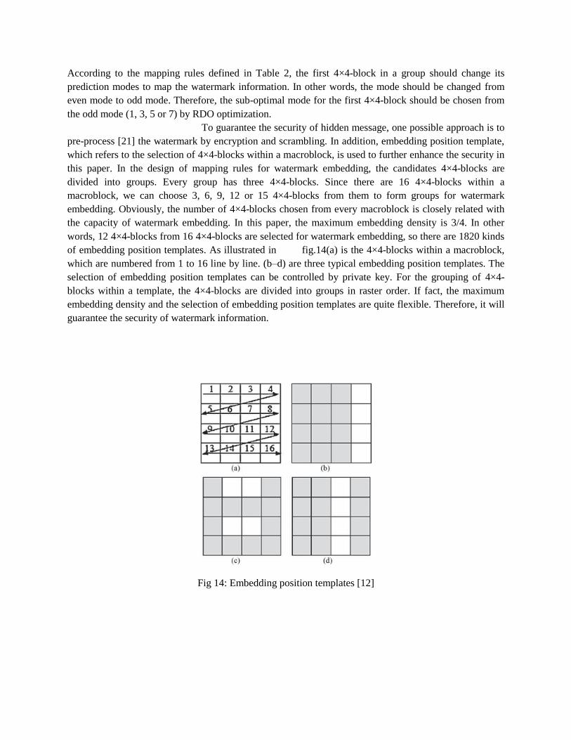
To guarantee the security of hidden message, one possible approach is to
pre-process [21] the watermark by encryption and scrambling. In addition, embedding position template,
which refers to the selection of 4×4-blocks within a macroblock, is used to further enhance the security in
this paper. In the design of mapping rules for watermark embedding, the candidates 4×4-blocks are
divided into groups. Every group has three 4×4-blocks. Since there are 16 4×4-blocks within a
macroblock, we can choose 3, 6, 9, 12 or 15 4×4-blocks from them to form groups for watermark
embedding. Obviously, the number of 4×4-blocks chosen from every macroblock is closely related with
the capacity of watermark embedding. In this paper, the maximum embedding density is 3/4. In other
words, 12 4×4-blocks from 16 4×4-blocks are selected for watermark embedding, so there are 1820 kinds
of embedding position templates. As illustrated in fig.14(a) is the 4×4-blocks within a macroblock,
which are numbered from 1 to 16 line by line. (b–d) are three typical embedding position templates. The
selection of embedding position templates can be controlled by private key. For the grouping of 4×4-
blocks within a template, the 4×4-blocks are divided into groups in raster order. If fact, the maximum
embedding density and the selection of embedding position templates are quite flexible. Therefore, it will
guarantee the security of watermark information.
Fig 14: Embedding position templates [12]

5. Watermarking Embedding and Extraction process:
5.1. Watermark embedding process
The block diagram of information hiding scheme is illustrated in fig.13. Based on the prerequisite to host
blocks as well as the mapping rule presented above, the proposed watermark embedding algorithm [12]
can be implemented as following:
1. Encrypt and permute the watermark information.
2. Prepare two embedding bits w.
3. Select the embedding position template by private key.
4. For the three candidate 4×4-blocks, modify MX based on w and the mapping rules. If no change of
intra-prediction modes in needed for these three 4×4-blocks, go to step 2.
5. Compute the new prediction mode of the 4×4-block to change its prediction mode, and re-encode it
with the new prediction mode.
6. Return to step 2 until all the watermark information are embedded.
Fig 15: Block diagram of watermark detection process [12]
5.2. Watermark detection process
The retrieval process corresponds to the dual of the embedding process. Block diagram of Watermark
detection process is illustrated in Fig. 15. The main steps are as following:
1. Partially decode the watermarked H.264/AVC video stream to get the prediction modes of all the 4×4-
blocks.
2. Determine the embedding position templates with the private key.
3. According to the embedding position templates, choose all the watermarked 4×4-blocks.
4. For every group in the watermarked 4×4-blocks, recover the embedded watermark bit by the mapping
rules.
5. Repeat step 4 until all the groups are finished.
6. Resemble the recovered watermark information, and then anti-scrambling and decryption of the
recovered watermark information, thus the original watermark information can be obtained.
Obviously, the retrieval of hidden information is simple and fast. It can be accomplished without the
original media and without complete decoding of input video stream. Only the prediction modes of those
intra-coded 4×4-blocks by partial decoding are enough to detect the hided watermark information.

6. Experimental Results
Test sequences used:
Test Sequence Resolution Frame Rate
grandma 670×480 30
news 670×480 30
silent 480×440 30
bridge 480×440 30
Table 3: Test Sequences
1. grandma 2. news
3. silent 4. bridge-close
Fig 16: Test sequences used

EMBEDDED IMAGE:
Fig 17: Embedded image of size 50×37 pel
RESULTS:
HBQ in pel
(Hidden Bit Quantity)
BRI in %
(Bit Rate Increase)
PSNRI in dB
(PSNR Increase)
Silent 1850 4.3 -0.05
Grandma 1850 4.1 -0.07
News 1850 5.9 -0.01
Bridge close 1850 3.8 -0.01
Table 4: Results after information hiding

TEST SEQUENCES AFTER HIDING:
1. grandma
Fig 18: grandma with and without information hiding
2. news
Fig 19: news with and without information hiding

3. silent
Fig 20: silent with and without information hiding
4. bridge-close
Fig 21: bridge-close with and without information hiding

CONCLUSION:
According to the results, the efficiency of this algorithm is not up to the mark and can try to
improve the hiding efficiency. Also this information hiding concept can be implemented in HEVC (High
Efficiency Video Coding)
7. References
[1] JVT Draft ITU-T recommendation and final draft international standard of joint video specification
(ITU-T Rec. H.264-ISO/IEC 14496-10 AVC), March 2003, JVT-G050 available on
http://ip.hhi.de/imagecom_G1/assets/pdfs/JVT-G050.pdf
[2] T.Wiegand et al, “Overview of the H.624/AVC Video Coding Standard”, IEEE Transactions on
Circuits and Systems for Video Technology, Vol.13, No.7, pp. 560-576, Jul. 2003.
[3] G.J.Sullivan et al, “Overview of the High Efficiency Video Coding (HEVC) standard,” IEEE Trans.
Circuits Syst. Video Technology, vol. 22, no. 12, pp. 1649–1668, Dec. 2012.
[4] Y.Tew and K.S.Wong, “An Overview of Information Hiding in H.264/AVC Compressed Video,”
IEEE Trans. Circuits Syst. Video Technol., vol. 24, no. 2, pp. 305-319, Feb 2014.
[5] I.E. Richardson, “The H.264 Advanced Video Compression Standard”, 2nd
edition, Wiley
publications, 21 May, 2010.
[6] T.A. Lin, S.Z. Wang, T.M. Liu and C.Y. Lee, “An H.264/AVC decoder with 4x4-block level
pipeline,” IEEE Signal Process. Lett., vol. 16, no. 2, pp. 91–101, Feb. 2009.
[7] Y.M. Huang, J.J. Leou, and M.H. Cheng, “A Post Deblocking Filter for H.264 Video,” IEEE Signal
Process. Lett., vol. 26, pp. 69–72, Feb. 2007.
[8] X.Li et al, “A generalization of LSB matching,” IEEE Signal Process. Lett., vol. 16, no. 2, pp. 69–72,
Feb. 2009.
[9] I.E.Richardson, “The H.264 Advanced Video Compression Standard”, 2nd
Edition, Hoboken, NJ,
Wiley, 2010.
[10] Feng Pan et al, “Fast Mode Decision for Intra Prediction”, ISO/IEC JTC1/SC29/WG11 and ITU-T
SG16 Q.6, JVT 7th Meeting Pattaya II, Thailand, 7-14, Mar 2003.
[11] C.S. Kim et al, “Fast Intra-Prediction Model Selection for H.264 Codec”, Integrated Media Systems
Center and Department of Electrical Engineering. Available on
http://citeseerx.ist.psu.edu/viewdoc/download?doi=10.1.1.2.4112&rep=rep1&type=pdf
[12] G.Yang et al, "An information hiding algorithm based on intra-prediction modes and matrix coding
for H.264/AVC video stream," AEU - International Journal of Electronics and Communications, vol.65,
no.4, pp.331-337, Mar 2010.
[13] Hu Y et al, “Information hiding based on intra prediction modes for H.264/AVC”, In: Proceedings of
IEEE International Conference on Multimedia and Expo., pp. 1231–1234, Aug 2007.
[14] J.Camenisch et al, “Modified matrix encoding technique for minimal distortion steganography”, 8th
International Workshop, IH 2006, LNCS 4437, pp. 314-327, Jul. 2007.
[15] S.K. Kapotas et al, “Real time data hiding by exploiting the IPCM macroblocks in H.264/AVC
streams”, Journal of Real-Time Image Processing, Vol.4, No.1, pp.33-42, Mar 2009.
[16] S. Li, “Detection of Information Hiding by Modulating Intra Prediction Modes in H.264/AVC”,
Proceedings of the 2nd International Conference on Computer Science and Electronics Engineering
(ICCSEE), volume 2, pp. 0590-0593, Jan 2013.
[17] PPT slides on “Fast Intra-Prediction Mode Selection for H.264”, by H.Zhang et al
Available online on: http://mathcs.slu.edu/~fritts/pres/spie05_IVC_h264_fast_mode_sel_pres.pdf
[18] E. Izquierdo et al, “Introduction to the Special Issue on Authentication, Copyright Protection, and
Information Hiding”, IEEE Transactions On Circuits And Systems For Video Technology, Vol. 13, No.
8, p.p. 729-731, Aug. 2003.
[19] B. Girod, “Video streaming with SP and SI frames”, In Proc. Visual Communication Image
Processing, Information Systems Laboratory, Stanford University, Mar. 2005.
[20] S. Kapotas and A. Skodras, “Real time data hiding by exploiting the IPCM macroblocks in
H.264/AVC streams,” J. Real-Time Image Process., vol. 4, pp. 33–41, Oct. 2009.
[21] C. Chang et al, “Hiding secret data in images via predictive coding,” Pattern Recognition, vol. 38,
no. 5, pp. 691–705, Sep. 2005.
[22] X. Li et al, “A generalization of LSB matching,” IEEE Signal Process. Letters, vol. 16, no. 2, pp. 69–
72, Feb. 2009.
[23] D. Marpe, H. Schwarz, and T. Wiegand, “Context-based adaptive binary arithmetic coding in the
H.264/AVC video compression standard,” IEEE Trans. Circuits Syst. Video Technol., vol. 13, no. 7, pp.
620–636, Jul. 2003.
[24] G. Bjontegaard and K. Lillevold, Context-Adaptive VLC (CAVLC) Coding of Coefficients, JVT-
C028, 3rd Meeting, Fairfax, Virginia, USA, May 2002.
[25] N. Ahmed et al, “Discrete Cosine Transform”, IEEE Transactions on Computers, Vol. C-23, pp. 90-
93, Jan.1974.
[26] Access to JM 18.6 Reference Software: http://iphome.hhi.de/suehring/tml/
[27] H.264 tutorial by I.E.G. Richardson: http://www.vcodex.com/h264.html
[28] I.E.G. Richardson, "H.264 and MPEG-4 Video Compression", Hoboken, NJ, Wiley, 2003.

[29] Atul Puri et al, "Video coding using the H.264/MPEG-4 AVC compression standard", Signal
Processing: Image Communication, vol. 19, pp. 793-849, Oct. 2004.
[30] Special issue on emerging research and standards in next generation video coding, IEEE
Transactions on Circuits and Systems for Video Technology (CSVT), vol.23, pp. 1646-1909, Dec.2012.
[31] Special issue on emerging research and standards in next generation video coding, IEEE
Transactions on Circuits and Systems for Video Technology (CSVT), vol.23, pp. 2009-2142, Dec.2013.
[32] Introduction to the issue on video coding HEVC and beyond, IEEE Journal of Selected Topics in
Signal Processing, vol.7, pp. 931-1151, Dec.2013.