information and instruction guide cost breakthrough for · pdf filemolded case circuit breaker...
TRANSCRIPT

Cost breakthroughfor up to 3200Aprotection
STD-Frame Solid State Molded Case Circuit BreakerInformation and Instruction Guide
Cost breakthroughfor up to 3200Aprotection

STD Frame Circuit Breakers (2000A, 2500A, and 3200A)Table of Contents
NOTE: Information related to specific frame types and catalog numbers does not guarantee product availability. Technical information may change due to product revisions. Consult Siemens sales office concerning any variation of information contained herein.
1
General Information 3-4Introduction 3Interruption and Short Time Ratings 3UL Listed Interruption and Short-Time Ratings 3IEC 947-2 Ratings 3Frame Sizes and Frame Ampere Ratings 3Rating Plugs 3Available Rating Plugs 3Overcurrent Protection Configurations 3RMS Current Sensing 3Circuit Breaker Operation 4Maintenance 4Description – Electronic Units for Siemens
STD Frame Circuit Breaker 5-6Electronic Trip Unit 5Overcurrent Protection Configurations 5Operations – Fault Protection Adjustments 7Trip Unit Current Shaping Adjustments 7Operations – Long-Time Fault Protection 8Adjustable Continuous Amps 8Adjustable Long Time Delay 8Operations – Short-Time Fault Protection 9Adjustable Short-Time Pickup 9Adjustable Short-Time Delay 9Operations – Instantaneous Fault Protection 10Adjustable Instantaneous Pickup 10Instantaneous Override 10Discriminator Circuit (Making Current Release) 10Operations – Ground Fault Protection 11Adjustable Ground Fault Pickup 11Adjustable Ground Fault Delay 11Ground Fault Memory Circuit 11Ground Fault Sensing Schemes 11Operations – Ground Fault Sensing Schemes 12Residual (3-Phase, 3-Wire) 12Residual (3-Phase, 4-Wire) 12Source Ground 12Operating Instructions – Monitoring the Electronic Trip Unit 13Trip Unit Test and Monitoring Functions 13System Check Indicator 13Trip Status 13Integral Test Modes 13Installation Instructions – Electronic Trip Unit 14-16Installation of Electronic Trip Unit 14Installation Instructions – Rating Plug 17-18Installation Test Procedure 19-21
Installation Instructions - Mounting of Auxiliary Switches 22-29
Internal Accessories - Trip Alarm Switches 30Installation Instructions - Mounting of
Shunt Trip Assembly 31-39Installation Instructions - Shunt Trip 40-42Installation Instructions - Mounting of Bell Alarm
or Display Relay 43-46Installation Instructions - Mounting of Remote
Indicator Panel 47-52Installation Instructions - Mounting of Pressure Wire Connector 53
Installation Instructions - Display Module or Ground Fault Monitor 54-56
Installation Instructions - Ground Fault Sensing and Relaying 57-61
Installation Instructions - Fixed MountedMechanical Interlock Assembly 62-63
Installation Instructions - Fixed Mounted Breaker Key Interlock 64
Installation Instructions - Mounting of Padlock Device Assembly 65-66
Installation Instructions - Mounting of Terminal Block Mount 67-68
External Accessories - Control Terminal Blocks 69Control Terminal Blocks 69Mounting Bracket for Terminal Block 69Installation Instructions - Mounting of Terminal
Connector 70Installation Instructions - Neutral Sensor 71-75External Accessories - MT and Expansion Plug for
Siemens ACCESS Communications System 76Installing Electronic Trip Units in Zone Selective
Interlocking or ACCESS Communications Systems 77-83External Accessories - Universal Test Kit 84General Information 84Operations 84External Accessories - Auxiliary Power Supply 85Test Procedures 85Outline Dimension Drawing - STD 3200A 86Ordering Information - Frames and Trip Units 87

IMPORTANT
The information contained herein is general in nature and not intended for specific application purposes. It does not relieve the user of responsibility to use sound practices in application, installation, operation, and maintenance of the equipment purchased. Siemens reserves the right to make changes in the specifications shown herein or to make improvements at any time without notice or obligations. Should a conflict arise between the general information contained in this publication and the contents of drawings or supplementary material or both, the latter shall take precedence.
NOTE
Authorized and qualified personnel—
For the purpose of this manual, a qualified person is one who is familiar with theinstallation, construction, or operation of the equipment and the hazards involved and:
(a) is trained and authorized to de-energize, clear, ground, and tag circuits and equipment in accordance with established safety practices.
(b) is trained in the correct care and use of protective equipment such as rubber gloves, hard hat, safety glasses or face shields, flash clothing, etc., in accordance with established safety practices.
(c) is trained in rendering first aid.
SUMMARY
These instructions do not purport to cover all details or variations in equipment, nor to provide for every possible contingency to be met in connection with installation, operation, or maintenance. Should further information be desired or should particular problems arise that are not covered sufficiently for the purchaser’s purposes, the matter should be referred to the local Siemens sales office listed on back of this instruction guide.
The contents of this instruction manual should not become part of or modify any prior or existing agreement, commitment, or relationship. The sales contract contains the entire obligation of Siemens Energy & Automation, Inc. The warranty contained in the contract between the parties is the sole warranty of Siemens Energy & Automation, Inc. Any statements contained herein do not create new warranties or modify the existing warranty.
2
Circuit breaker indicators shown in this booklet are for illustration purposes only. Circuit breakers are to be installed in “Tripped” or “Open” positions only.
DANGERHazardous voltage.Will cause death or serious injury.
Turn off and lock out all power supplying the device prior to cover(s) removal or while cover(s) are removed and when installing any internal or external accessory.
Replace the cover(s) and shield(s) before power supplying this device is turned on.

IntroductionSiemens STD Frame Circuit Breakers offer current ratingsup to 3200 Amps in a microprocessor-controlled MoldedCase Circuit Breaker (MCCB).
With maximum ratings of 2000A, 2500A, and 3200A, STD Frame Breakers are suitable for many industrial andcommercial applications. The available 150 KA (480V) interrupting rating leads the industry for a MCCB in thisrange.
Interruption and Short-Time RatingsThis breaker is available in three interrupting ratings. Theinterruption ratings and short-time ratings are listed in thefollowing table.
UL-Listed Interruption and Short-Time Ratings
NOTE: Information contained here refers to product instructions and procedures and is not intended to indicate availability.
IEC 947-2 RatingsThese ratings apply to high (SHTD) interrupting rating only.
Frame Sizes and Frame Ampere RatingsThe STD Frame Breaker is available in three frame ratings:2000A, 2500A, and 3200A. These frames are also offered in a version rated for 100% continuous operation.Refer to page 87.
Rating PlugsThe STD Frame Breaker is designed to use interchangeablerating plugs. With a rating plug, you can customize the effective ampere rating of the breaker to meet specific applications. The available rating plugs are listed in the following table.
Available Rating Plugs
Overcurrent Protection ConfigurationsSiemens Electronic Trip Units for the STD Frame breaker are available in seven overcurrent protection configura-tions to meet specific needs. The optional protection configurations are as follows:
RMS Current SensingThe Siemens microprocessor-controlled Electronic Trip Unit executes the overcurrent fault protection functions of the STD Frame Breaker.
The adjustment flexibility provided by the trip unit allows you to accommodate load changes and other protection requirements while still assuring optimum coordination and protection.
A standard feature of the trip unit is RMS current sensing. RMS sensing measures the true heating potential of the current waveform. RMS sensing allows for more accurate overcurrent protection and virtually eliminates nuisance tripping due to harmonic distortion of the currentwaveform.
General Information
3
Protection Configuration Identifier
Long Time/Short Time LSLong Time/Instantaneous LILong Time/Short Time/Instantaneous LSILong Time/Short Time/Ground Fault LSGLong Time/Instantaneous/Ground Fault LIGLong/Short Time/Instantaneous/Ground Fault LSIGFixed Long Time/Instantaneous MLI
Interrupting Type 240V 480V 600V Rate AC AC AC
Standard STD 85 65 50High SHTD 150 100 85Extra High SHHTD 200 150 100Short-Time Rating (T = 0.5 sec) = 50KA
AC Voltage 3200A Frame
Icu 100415 Ics 100
Icw 50Icu 65
690 Ics 65Icw 50
Interrupting Ratings SymmetricalRMS Amperes50/60 Hz.
Max Rating Rating Plug Ampere Values (In)
2000 1000, 1200, 1600, 20002500 1600, 2000, 2500 3200 1600, 2000, 2500, 3000, 3200

Circuit Breaker OperationWith the mechanism latched and the contacts open, the operating handle is in the OFF position. Moving the handle to the ON position closes the contacts and establishes a circuit through the circuit breaker.
Under an overload or a short-circuit condition sufficient to trip the breaker automatically, the operating handle moves to a position between ON and OFF.
To relatch the circuit breaker after automatic operation, move the operating handle to the extreme OFF position. The circuit breaker is now ready for reclosing.
The overcenter toggle mechanism is trip free of the operating handle. This means an operator cannot use the handle to hold the circuit breaker closed when the unit is tripped.
After automatic operation, the handle moves to an inter-mediate position between ON and OFF, which indicates that it has been tripped.
MaintenanceProperly applied MCCBs normally do not require mainte-nance. However, you may wish to establish a routine inspection program. For detailed information, consult applicable NEMA publications or contact your local Siemens sales office.
General Information
4

Electronic Trip UnitThis Electronic Trip Unit is a microprocessor controlled, multifunctional, overcurrent protective device for applica-tion with Siemens state-of-the-art STD Frame molded-case Circuit Breakers.
The adjustment flexibility provided by the trip unit allows you to easily accommodate load changes and other protective requirements while still assuring optimum coordination.
In addition to the adjustable protection functions, the trip unit is designed to use field-interchangeable rating plugs.These rating plugs allow the ampere rating of the breaker to be changed to meet specific applications.
For ease of installation and interchangeability in the field, the trip unit has been designed as a plug-in unit to mountdirectly unto an STD Frame breaker frame.
Current sensors within the STD Frame breakers provide signal currents and operating power for the trip unit. Therefore, the trip unit requires no external connections or control power to perform its protection functions.
Overcurrent Protection ConfigurationsThe units are available in seven overcurrent protection configurations to meet specific protection requirements. Six trip units have Adjustable Continuous Current and Long Time Delay. Optional protection configurations are:
As standard features, the trip unit has two built-in test functions and a fault identification function.
System Check is a built-in test function that continuouslychecks the status of the microprocessor and protective algorithms. A green LED on the front panel blinks approx-imately every three seconds when the microprocessor is correctly executing its protection routines.
Integral Test is a built-in test that allows the user to exer-cise the trip unit electronics. LED indicators display the testing status.
Trip Status is a fault identification function that stores information when the trip unit trips the circuit breaker. Bypressing the Query button, you can display the cause of thebreaker trip by illuminating one of four LED’s. OL (overload), ST (short time), SC (short circuit), or GF (ground fault). Newer version trip units provide a Fault LEDReset Button for clearing the indicator.
Additional optional features include: Display Module for local current monitoring (field addable), Zone Selec-tive Interlocking Communications for remote monitoring, and a Ground Fault Monitor for Ground Fault Warning applications.
DescriptionElectronic Trip Units For Siemens STD Frame Circuit Breakers
5
Protection Configuration Identifier
Long Time/Short Time LSLong Time/Instantaneous LILong Time/Short Time/Instantaneous LSILong Time/Short Time/Ground Fault LSGLong Time/Instantaneous/Ground Fault LIGLong/Short Time/Instantaneous/Ground Fault LSIGFixed Long Time/Instantaneous MLI

NOTE: Earlier model trip units may use (Ir) as the RatingPlug designator and (In) to denote (Max Rating). The desig-nations for the current model trip unit are shown at right.Note however, that the change in designation has no effecton the switch settings used for selecting Continuous, LongTime, Short Time, Instantaneous, and Ground Fault pickupand delay values.
In addition, a Trip Status Reset Button is provided on newerversion trip units for clearing the Trip Status LED’s.
DescriptionElectronic Trip Units For Siemens STD Frame Circuit Breakers
6
SYSTEMCHECK
Continuous
LongTimeDelay
Rating Plug
ln = 1000A
ShortTimeDelay
xln
Secs@8 x ln
ShortTimePickup
81.5
2
2.53 3.5
4
5
67
.3.07
.1
.15.2 .3
.07
.1
.15.2 I2t
Fixed
InstantaneousPickupxln
101.5
2
34 5
6
7
89
GroundFaultDelay
.5.1
.2
.3.4 .5
.1
.2
.3.4 I2t
Fixed
MAX RATING = 2000A
GroundFaultPickup
3020
21
2223 24
25
26
2728
Phase G.F.Trip
APM
TEST
TS31
TestingPass
Query TripStatus O.L. S.T. S.C. G.F.
DisplayModule
Amps
10050
60
6570 75
80
85
9095
302.5
4
5.58 10
14
17
2125
Secs@6 x ln
Load MonitorAlarm Set PointsContinuous Amps%
90100
Present Demand
Maximum DemandIA IB
60
7080
IC
Meter
SIEMENSlr = % In
lg = %MaxRating
Secs@1000A
Typical Trip Adjustment Unit Panel
Rating Plug
Curve Adjustments
Fault Indicators
Plug-inDisplay Module
Built-inTest Functions

OperationsFault Protection Adjustments
7
(1) Continuous Ampere Setting RegionThe allowable continuous operating amperes is set to a percent of the rating-plug value. Note that the maximum continuous ampere is set by the rating-plug value (In).
(2) Long-Time Delay RegionThe long-time delay is set to an inverse I2t ramp function delay calibrated at 6 times the rating-plug value (In).
(3) Short-Time Pickup RegionThe short-time pickup is set to a multiple of the rating-plug value (In).
(4) Short-Time Delay RegionThe short-time delay is set to either a fixed delay (illustrated) or an inverse I2t ramp function delay calibrated at 8 times the rating-plug value (In).
(5) Instantaneous Pickup RegionThe instantaneous pickup is set to a multiple of the rating-plug value (In).
(6) Ground-Fault Pickup RegionGround-fault pickup is set to a percent of the Max Rating.
(7) Ground-Fault Delay RegionThe ground fault delay is set to either a fixed delay (illustrated) or an inverse I2t ramp function delay calibrated at one-half of the Max Rating.
Trip Unit Current Shaping Adjustments (This curve is for illustration purposes only.)
Amperes in Multiples of Rating Plug Value (In)
lg = % Max Rating
0.110,000
1,000
100
10
0.01
0.1
1
10 100 1000
0.01
0.1
1
10
1
1 C
ycle
Tim
e i
n S
eco
nd
s
1 C
ycle
T
ime i
n S
eco
nd
s
1
2
3
5
6
74

Adjustable Continuous Amps
The Continuous Ampere Adjustment sets the current level at which the breaker will continuously operate without initiating a tripping sequence. The continuous operating current may be set to 50%, 60%, 65%, 70%,75%, 80%, 85%, 90%, 95%, and 100% of the rating plug value (In).
Adjustable Long-Time DelayThe long-time pickup is nominally set at 115% of the continuous amps setting.
The long-time delay adjustment is used to set the tripping delay of the STD Frame breaker based on the magnitude of the overcurrent.
On Siemens Electronic Trip Units, the long-time delay, whichis an inverse I2t ramp function, may be set to a calibrated value of 2.5, 4, 5.5, 8, 10, 14, 17, 21, 25, or 30 sec-onds at a current equal to 6 times the rating plug value (In).
OperationsLong-Time Fault Protection
8
SYSTEMCHECK
Continuous
LongTimeDelay
Rating Plug
ln = 3200
10050
60
6570 75
80
85
9095
302.5
4
5.58 10
14
17
2125
Secs@6 x ln
SIEMENSlr = % ln
100
50
60
65
70 7580
85
9095
Available Switch Settingsfor Adjustable Continuous Amps
Continuous Operating Current
Long-Time Delay
0.110,000
1,000
100
10
0.1
1
1 10 100 xln
Tim
e I
n S
eco
nd
s
0.110,000
1,000
100
10
0.01
0.1
1
1 10 100 xln
Tim
e I
n S
eco
nd
s
Available Switch Settingsfor Adjustable Long Time Delay
LongTimeDelaySecs@ 6xln
302.5
4
5.58 10
14
17
2125
Continuous
Operating
Current
Continuous
Operating
Current
Long TimeDelay
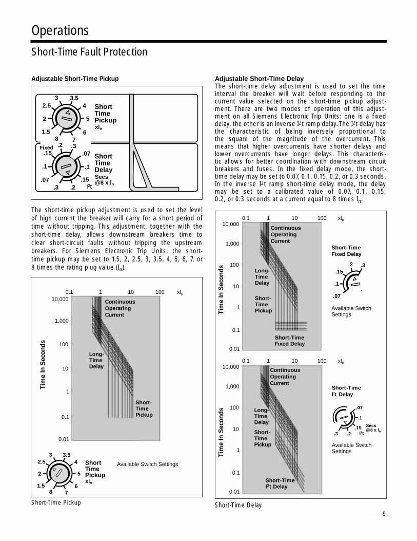
Adjustable Short-Time Pickup
The short-time pickup adjustment is used to set the level of high current the breaker will carry for a short period of time without tripping. This adjustment, together with the short-time delay, allows downstream breakers time to clear short-circuit faults without tripping the upstream breakers. For Siemens Electronic Trip Units, the short- time pickup may be set to 1.5, 2, 2.5, 3, 3.5, 4, 5, 6, 7, or 8 times the rating plug value (In).
Short-Time Pickup
Adjustable Short-Time DelayThe short-time delay adjustment is used to set the time interval the breaker will wait before responding to the current value selected on the short-time pickup adjust-ment. There are two modes of operation of this adjust-ment on all Siemens Electronic Trip Units: one is a fixeddelay, the other is an inverse I2t ramp delay. The I2t delay hasthe characteristic of being inversely proportional to the square of the magnitude of the overcurrent. This means that higher overcurrents have shorter delays andlower overcurrents have longer delays. This characteris-tic allows for better coordination with downstream circuitbreakers and fuses. In the fixed delay mode, the short-time delay may be set to 0.07, 0.1, 0.15, 0.2, or 0.3 seconds.In the inverse I2t ramp short-time delay mode, the delaymay be set to a calibrated value of 0.07, 0.1, 0.15, 0.2, or 0.3 seconds at a current equal to 8 times In.
Short-Time Delay
OperationsShort-Time Fault Protection
9
ShortTimeDelaySecs@8 x ln
.3.07
.1
.15.2 .3
.07
.1
.15.2 I2t
Fixed
xln
ShortTimePickup
81.5
2
2.53 3.5
4
5
67
.07
.1
.15.2 .3
Short-Time
Fixed Delay
Available SwitchSettings
Secs@8 x ln
.3
.07
.1
.15.2 I2t
Short-Time
l2t Delay
Available SwitchSettings
xln
ShortTimePickup
81.5
2
2.53 3.5
4
5
67
Available Switch Settings
Continuous
Operating
Current
Long- TimeDelay
Short- TimePickup
0.110,000
1,000
100
10
0.01
0.1
1
1 10 100 xln
Tim
e I
n S
eco
nd
s
0.110,000
1,000
100
10
0.01
0.1
1
1 10 100 xlnT
ime I
n S
eco
nd
s
0.110,000
1,000
100
10
0.01
0.1
1
1 10 100 xln
Tim
e I
n S
eco
nd
sContinuous
Operating
Current
Long- TimeDelay
Short- TimePickup
Short-TimeFixed Delay
Continuous
Operating
Current
Long- TimeDelay
Short- TimePickup
Short-Timel2t Delay

Adjustable Instantaneous Pickup
The instantaneous-pickup adjustment is used to set the current level at which the breaker will trip without an intentional time delay. Nondelayed tripping, as a result of a severe overcurrent condition, minimizes potential damageto electrical systems and equipment. The instanta-neous-pickup adjustment may be set to 1.5, 2, 3, 4, 5, 6, 7, 8, 9, or 10 times the rating plug value (In).
Instantaneous Pickup
Instantaneous OverrideOn all trip units, an instantaneous override function has been provided. It is set at the approximate short-time rating of the respective breaker frame size. This allows the breaker to ride through high faults up to its short-time capability; however, it is self-protecting above these values.
Discriminator Circuit (Making Current Release)This circuit overrides the short-time delay function should the breaker attempt to close into a faulted system, tripping the breaker instantaneously. The discriminator function is enabled for the first six cycles of current flow,after which normal short-time characteristics operate.
Instantaneous Override (Illustrated with Short-Time FixedDelay)
OperationsInstantaneous Fault Protection
10
STD Breaker Short Time kA RatingFrame Size (0.500 seconds max.)
3200A 50
InstantaneousPickupxln
101.5
2
34 5
6
7
8 9
Available Switch Settings
Continuous
Operating
Current
Long- TimeDelay
InstantaneousPickup
Continuous
Operating
Current
Long- TimeDelay
Short-TimePickup
Short-TimeFixed Delay
InstantaneousOverride
0.110,000
1,000
100
10
0.01
0.1
1
1 10 100 xln
Tim
e I
n S
eco
nd
s
0.110,000
1,000
100
10
0.01
0.1
1
1 10 100 xlnT
ime I
n S
eco
nd
s
InstantaneousPickupxln
101.5
2
34 5
6
7
8 9

Adjustable Ground Fault PickupThe ground-fault pickup adjustment is used to set the level of ground current at which circuit interruption will be initi-ated. Together with the ground-fault delay, this adjustmentallows selective tripping between main and feeder or other downstream breakers. The available ground fault pick-up settings as a percent of the STD Max Rating are listed below. In compliance with the National Electric Code(NEC 230-95), no trip point setting exceeds 1200A.
Adjustable Ground Fault DelayThe ground-fault delay adjustment is used to set the time interval the breaker will wait before responding once theground-fault pickup level has been reached. There are two modes of operation for this adjustment for SiemensElectronic Trip Units; one is a fixed delay and the other is an inverse I2t ramp delay. In the fixed delay mode, the ground-fault delay may be set to 0.1, 0.2, 0.3, 0.4, or 0.5 seconds. In the inverse I2t delay mode, the delay may be set to a calibrated value of 0.1, 0.2, 0.3, 0.4, or 0.5 sec-onds at a current equal to 0.5 times the Max Rating. Theinverse I2t ramp delay reverts to a fixed delay of the samevalue when the ground current (Ig) exceeds 50% of theMax Rating.
Ground Fault Memory CircuitElectronic Trip Units with ground fault protection comeequipped with a ground fault memory circuit. This circuit integrates ground fault currents with time. This provides added protection by preventing ground fault delay circuits from being reset to zero when the ground fault currents are intermittent and erratic. Time constants for the
current integration are preset within the trip unit as a function of the Ground Fault Delay.
Ground Fault Sensing SchemesThe trip unit can be configured to accommodate the following ground fault sensing schemes.
• 3-Phase, 3-Wire Residual• 3-Phase, 4-Wire Residual• Source Ground
All that is required of the user to configure the trip unit to support these protection schemes is to set the ground fault selection switch to the desired configuration. Theselection switch is on the left side of the trip unit and must be set prior to the trip unit being installed in the STB breaker.
OperationsGround Fault Protection
11
GroundFaultDelay
.5.1
.2
.3.4 .5
.1
.2
.3.4 I2t
Fixed
MAX RATING = 2000A
GroundFaultPickup
3020
21
2223 24
25
26
2728
lg =Max Rating
%
Secs@ 1000A
Max Setting = Rating % Max Rating
3200A 20 21 23 25 27 29 31 33 35 37
2500A 20 23 26 29 32 35 38 41 44 48
2000A 20 21 26 29 32 35 38 41 44 48
Fixed Ground
Fault Delay
Available SwitchSettings
Adjustable Ground
Fault 12t Delay
Available SwitchSettings
.1
.2
.3.4 .5
.0110
1
0.1
0.01
0.1 1.0 10 xln
Tim
e I
n S
eco
nd
s
.0110
1
0.1
0.01
0.1 1.0 10 xln
Tim
e I
n S
eco
nd
s
.5
.1
.2
.3.4 I2t
GroundFaultPickup
Ground FaultFixed Delay
GroundFaultPickup
Ground Faultl2t Delay
Secs@1000A
Ground Fault Delay
The following are brief descriptions of the ground fault sensing schemes as they relate to the Siemens Elec-tronic Trip Unit. Detailed technical and application infor-mation of the ground fault sensing schemes is contained in NEMA Standard No. PB 2.2 “Application Guide for Ground Fault Protective Devices for Equipment.”
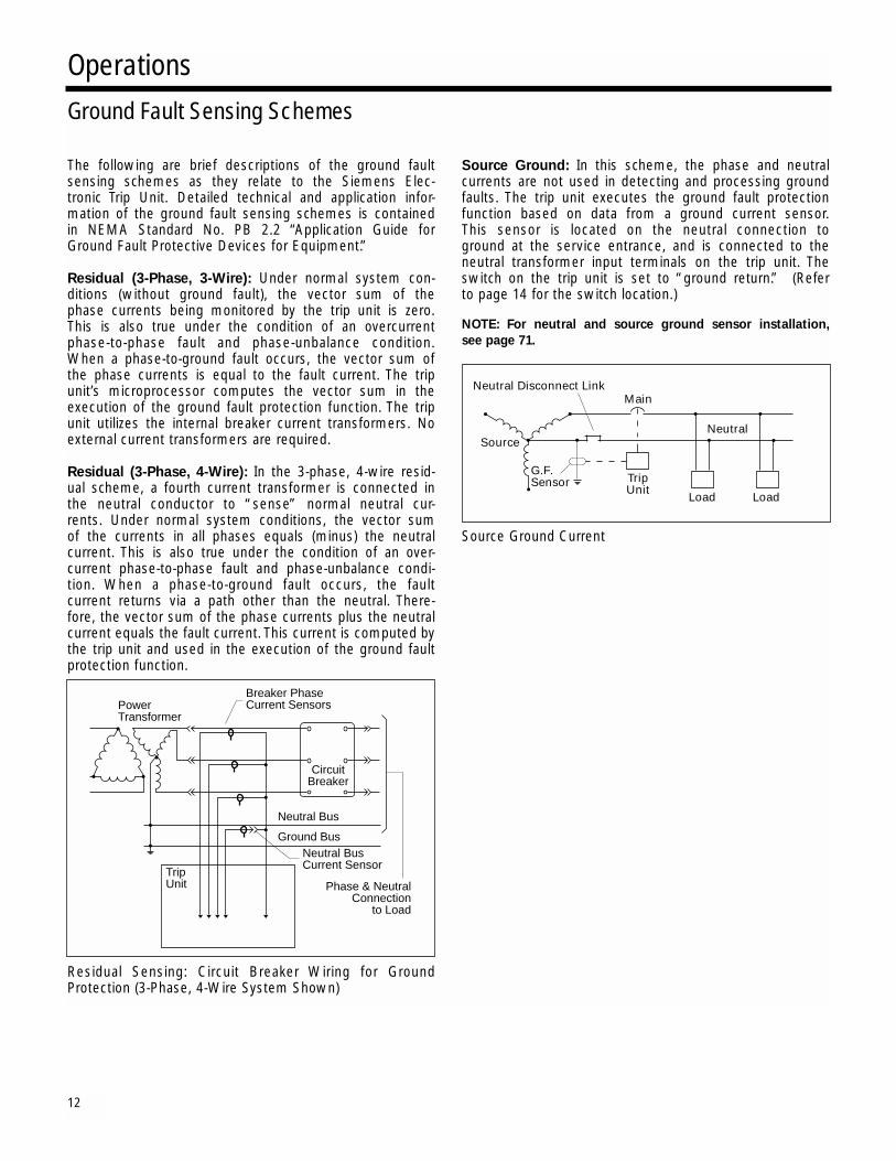
Residual (3-Phase, 3-Wire): Under normal system con-ditions (without ground fault), the vector sum of the phase currents being monitored by the trip unit is zero. This is also true under the condition of an overcurrent phase-to-phase fault and phase-unbalance condition. When a phase-to-ground fault occurs, the vector sum of the phase currents is equal to the fault current. The trip unit’s microprocessor computes the vector sum in the execution of the ground fault protection function. The trip unit utilizes the internal breaker current transformers. No external current transformers are required.
Residual (3-Phase, 4-Wire): In the 3-phase, 4-wire resid-ual scheme, a fourth current transformer is connected in the neutral conductor to “sense” normal neutral cur-rents. Under normal system conditions, the vector sum of the currents in all phases equals (minus) the neutral current. This is also true under the condition of an over-current phase-to-phase fault and phase-unbalance condi-tion. When a phase-to-ground fault occurs, the faultcurrent returns via a path other than the neutral. There-fore, the vector sum of the phase currents plus the neutral current equals the fault current. This current is computed bythe trip unit and used in the execution of the ground faultprotection function.
Residual Sensing: Circuit Breaker Wiring for GroundProtection (3-Phase, 4-Wire System Shown)
Source Ground: In this scheme, the phase and neutral currents are not used in detecting and processing groundfaults. The trip unit executes the ground fault protection function based on data from a ground current sensor. This sensor is located on the neutral connection to ground at the service entrance, and is connected to the neutral transformer input terminals on the trip unit. Theswitch on the trip unit is set to “ground return.” (Refer to page 14 for the switch location.)
NOTE: For neutral and source ground sensor installation,
see page 71.
Source Ground Current
OperationsGround Fault Sensing Schemes
12
G.F.Sensor
NeutralSource
TripUnit
Load Load
MainNeutral Disconnect Link
TripUnit Phase & Neutral
Connectionto Load
PowerTransformer
Breaker PhaseCurrent Sensors
CircuitBreaker
Neutral Bus
Neutral BusCurrent Sensor
Ground Bus

Trip Unit Test and Monitoring FunctionsSiemens Electronic Trip Unit is equipped with three standard test and monitoring functions to aid in the instal-lation and operation of the STD Frame breaker.
System Check Indicator
The System Check Indicator is a green LED that blinks approximately once every three seconds when the microprocessor is correctly executing its protectionroutines.
The trip unit derives its operating power from the phase currents in the STD Frame breaker. The phase current required to operate the trip unit is approximately 20% of the Max Rating. If the microprocessor is not func-tioning or the phase current is below the 20% value, theLED will not light.
Trip StatusNOTE: Newer version Trip Units feature a Trip Status Reset Button for clear-
ing the Trip Status LED’s.
The trip Query button and Trip Status indicator lights allow the user to determine what type of fault caused thetrip unit to trip the breaker. Fault indicators are provided for:
• O.L. – Overload or Long Time Fault• S.T. – Short Time Fault• S.C. – Short Circuit or Instantaneous Fault• G.F. – Ground Fault
When a fault occurs, the fault information is stored in the trip unit. When the Query button is depressed, thelatched fault indicator will light. The energy to power the indicators is automatically stored in the trip unit, elimi-nating the need for a battery. A hole is provided in the transparent cover to allow access to the Query button.
NOTE: During trip unit power up, a fault indicator LED will latch, providing
a means to check that the circuitry is correctly operating. In case of a fault,
the correct indicator will be latched to the fault position.The indicator cir-
cuitry will latch the most recent event.
Integral Test Modes
The integral test function enables the user to “exercise” the trip unit electronics, the magnetic latch, and the breaker mechanism. The purpose of the integral test function is to provide the user an easy means to conduct a “go/no go” test before bringing the breaker on-line.After the breaker has been brought on-line, it may be used during routine inspection and maintenance.
Both phase fault current protection and ground fault currentprotection may be tested. The integral ground fault testfunction tests the circuit breaker’s ground fault pro-tection system.
Electrical power to operate the integral test function is provided internally if the breaker is closed and the phasecurrents are greater than 20% of the Max Rating, or by aplug-in power source (see Accessories section).
The user may execute the test function in either a “no trip” mode, which will test only the trip unit electronics, or a “trip” mode, which will also test the magnetic latch and breaker mechanism. The execution of the integral test function in both the “no trip” and “trip” modes is based on the settings of the long time delay and ground fault delay adjustments. Therefore, the Phase Test will take several seconds to execute and the Ground Fault Test will appear to be nearly instantaneous.
To execute a test in the “no trip” mode, depress the appropriate pushbutton (Phase or GF). As the trip unit is performing the test, the Testing Indicator will light. If the trip unit successfully passes the test, the Pass Indicator will light. If the Pass Indicator does not light after the TestingIndicator indicates that the test is complete, a more extensive test should be run with Siemens TS-31Universal Test Kit (see Accessories).
To exercise the magnetic latch and breaker mechanism,select a “trip mode” test. To do this, press the appropri-ate test button (Phase or GF) while pressing the trip button.
OperationsMonitoring the Electronic Trip Unit
13
SYSTEMCHECK
ContinuousSIEMENS
%lr
10050
60
6570 75
80
85
9095
Rating Plug
ln = 3200A
Query TripStatus O.L. S.T. S.C. G.F.
CAUTIONBefore doing a “Trip” test on an STDFrame that is “Closed” and in service,caution should be taken to evaluate effects on downstream loads. Breaker will open during test, resulting in a disruption of service.
Phase G.F.Trip
APM
TEST
TS31
TestingPass

Installation of Electronic Trip UnitThe STD Frame breaker has a built-in interlock device that prevents the breaker from being closed when thereis no trip unit installed. This same interlock device will trip the breaker when the trip unit is removed.
To install the trip unit, the front cover of the breaker must first be removed.
1. Remove 8 screws from breaker front cover.
2. Lift off front cover.
On trip units with ground fault protection, the ground fault selection switch on the side of the trip unit must be set to the appropriate sensing scheme—Residual or Source Ground— before installing the trip unit. The trip unit is preset at the factory to a residual sensing scheme.
3. Set ground fault selection switch.
Installation InstructionsElectronic Trip Unit
14
WARNINGDo not attempt to install a trip unitwith the breaker “Closed.” Make certainbreaker is “Tripped.” Personal injury ormechanical damage may occur.
67
5
4
8
2
1
3
DANGERHazardous voltage.Will cause death or serious injury.
Turn off and lock out all power supplying the deviceprior to cover(s) removal or while cover(s) are removedand when installing any internal or external accessory.
Replace the cover(s) and shield(s) before power supply-ing this device is turned on.

Before attempting to install the trip unit, check the label on the side of the unit to make sure that it is the correct unit for the STD Frame breaker. A mechanical rejectionscheme will prevent the installation of a trip unit into abreaker for which it is not intended.
4. Check label on side of trip unit.
5. Check alignment of pins and holes.
6. Mate pin connectors.
Mate the connector half on the back of the trip unit with its corresponding connector half in the breaker.
7. Lower trip unit onto support plate.
After the connector has been mated, lower (push) the trip unit onto the support plate. The pins on the support plate will fit into the holes in the bottom of the trip unit.
8. Secure trip unit.
Secure the trip unit in place with the retaining screw located at the top of the trip unit. Torque 6 to 8 in-lbs (.7 –.9 Nt-mtr). If trip unit top is not secured correctly, theinterlock will prohibit closing of the breaker.
NOTE: Before energizing the breaker, be sure to install a correct rating plug. See page 17
Installation InstructionsElectronic Trip Unit
15
Installation InstructionsElectronic Trip Unit
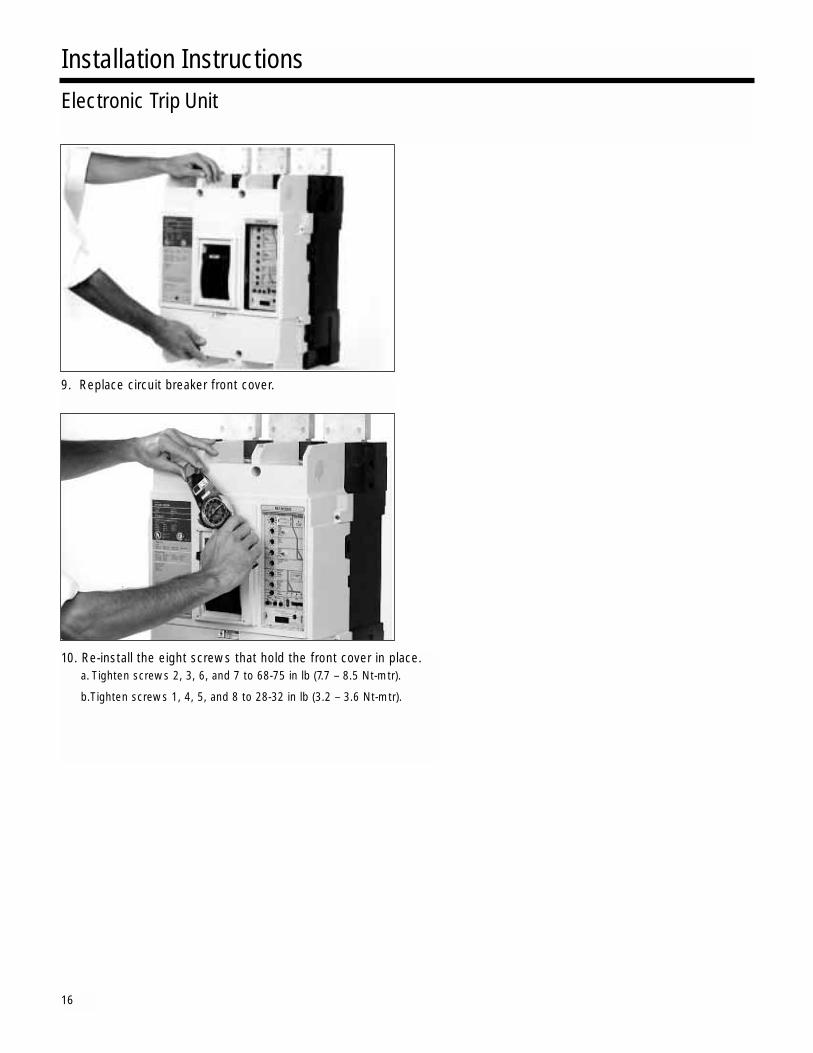
9. Replace circuit breaker front cover.
10. Re-install the eight screws that hold the front cover in place.a. Tighten screws 2, 3, 6, and 7 to 68-75 in lb (7.7 – 8.5 Nt-mtr).
b.Tighten screws 1, 4, 5, and 8 to 28-32 in lb (3.2 – 3.6 Nt-mtr).
16

Breaker should always be in the “Open” position whenthere is no rating plug in the trip unit.
1. Remove trip unit screws that hold the transparent cover.
The rating plug and adjustments on the front panel of the trip unit are protected by a transparent cover. Prior to installing a rating plug or setting the adjustments on the trip unit, this cover must be removed. Unscrew the two screws that hold it in place, and carefully pry the cover loose with a small screwdriver.
2. With a small screwdriver, gently pry the cover loose at one end and remove it carefully.
3. Check label on the rating plug.
Check the rating plug label to verify that it is a correct plug for the trip unit. If it is not a correct plug, the pins will not mate with the plug receptacle.
4. To insert rating plug, align plug receptacle and press into place.
To insert a rating plug in the trip unit, align the plug with the plug receptacle and press the plug into place. The clips on the plug hold it in place.
To remove a rating plug, squeeze the clips and pull the plug from the plug receptacle. Since the plug is held in place by compression, some force will be required toremove the plug.
Installation InstructionsRating Plug
17
WARNINGDo not attempt to install or remove arating plug with the breaker “Closed”or “Charged.” Personal injury or mechanicaldamage may occur. Make certain breaker is “Open” or “Discharged.”
DANGERHazardous voltage.Will cause death or serious injury.
Turn off and lock out all power supplying the deviceprior to cover(s) removal or while cover(s) are removedand when installing any internal or external accessory.
Replace the cover(s) and shield(s) before power supply-ing this device is turned on.
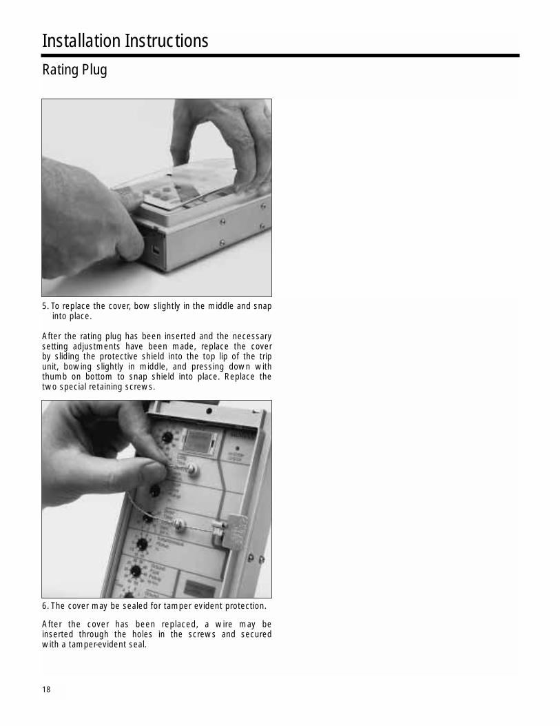
5. To replace the cover, bow slightly in the middle and snap into place.
After the rating plug has been inserted and the necessary setting adjustments have been made, replace the cover by sliding the protective shield into the top lip of the trip unit, bowing slightly in middle, and pressing down with thumb on bottom to snap shield into place. Replace the two special retaining screws.
6. The cover may be sealed for tamper evident protection.
After the cover has been replaced, a wire may be inserted through the holes in the screws and secured with a tamper-evident seal.
Installation InstructionsRating Plug
18

SAFETY INSTRUCTIONS
Siemens Energy & Automation, Inc.Bellefontaine, OH 43311 U.S.A.
Hazardous voltage.Will cause death or seriousinjury.Turn off and lock out all powersupplying the device prior to cover(s)removal or while cover(s) are removedand when installing any internal orexternal accessory.Replace the cover(s) and shield(s)before power supplying this device isturned on.
Installation Test Procedure
Item: Installation Test Procedure
For Use With: Siemens’ Circuit Breakers with Integral GroundFault Protection
Type: STD62000, STD62500, STD63200, SHTD62000,SHTD62500, SHTD63200, SHHTD62000, SHHTD62500,SHHTD63200, TD62000, TD62500, and TD63200
Page 1 of 3
GENERALThe Siemens Type STD circuit breaker may beequipped with integral ground fault protection.These devices are identified by a "G" in the trip unitcatalog number and the presence of the ground faultadjustments. The National Electrical Code® re-quires that these devices be performance testedwhen first installed [215-10, 230-95 (c), 240-13].These instructions are intended to guide the installerin meeting this requirement.
GENERAL INSTRUCTIONS1. The interconnected system shall be evaluated
by qualified personnel when initially installed. Itis also suggested this be done periodically there-after.
2. The proper location of the sensors around thebus of the circuit to be protected shall be deter-mined. This can be done visually, with knowl-edge of which bus is involved.
3. The grounding points of the system shall be veri-fied to determine that ground paths do not existthat would bypass the sensors.
4. The polarity of the sensor connections mustagree with the installation instructions to avoidimproper operation.
National Electrical Code® is a Registered Trademark of the National Fire Protection Association.
5. A simulated test is to be done using a low-volt-age, high-current source. This test is not in-tended to verify the calibration of the ground faultprotection but to verify it is properly functioning.
6. The results of this testing should be recorded onthe form provided at the end of this document oron other appropriate forms and should be avail-able to the inspection authority.
7. These breakers may be set for different modesof operation, Residual or Ground Return, as de-scribed in the instructions supplied with the cir-cuit breaker. For further information on applica-tions, refer to the NEMA standards publicationNo. PB 2.2 Application Guide For Ground FaultProtective Devices for Equipment.1
OPERATION TEST
SWITCH SETTING - RESIDUALOutgoing Circuit Method3 Phase / 3 Wire
Using Figure 1, individually test breaker poles A, B,and C for proper Ground Fault operation.
Each of the circuit breaker's front panel controlsshould be set to the highest setting. Using a low-voltage current source, apply a test current equalto 125 percent of the ground fault pickup setting toone pole of the circuit breaker. The circuit breakermust trip.
Figure 1
_ _ _ _ _ _ _ _ _ LINE
_ _ _ _ _ _ _ _ _ LOAD
A B C
A B C
A.C.GENERATOR
~
Installation Test Procedure
19
20
Siemens Energy & Automation, Inc.Bellefontaine, OH 43311 U.S.A.
Hazardous voltage.Will cause death or seriousinjury.Turn off and lock out all powersupplying the device prior to cover(s)removal or while cover(s) are removedand when installing any internal orexternal accessory.
Replace the cover(s) and shield(s)before power supplying this device isturned on.
Installation Test ProcedureWARNING:
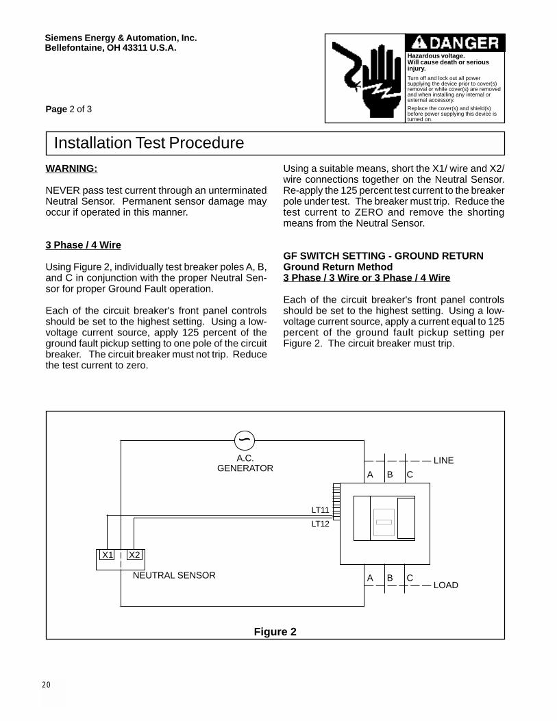
NEVER pass test current through an unterminatedNeutral Sensor. Permanent sensor damage mayoccur if operated in this manner.
3 Phase / 4 Wire
Using Figure 2, individually test breaker poles A, B,and C in conjunction with the proper Neutral Sen-sor for proper Ground Fault operation.
Each of the circuit breaker's front panel controlsshould be set to the highest setting. Using a low-voltage current source, apply 125 percent of theground fault pickup setting to one pole of the circuitbreaker. The circuit breaker must not trip. Reducethe test current to zero.
Using a suitable means, short the X1/ wire and X2/wire connections together on the Neutral Sensor.Re-apply the 125 percent test current to the breakerpole under test. The breaker must trip. Reduce thetest current to ZERO and remove the shortingmeans from the Neutral Sensor.
GF SWITCH SETTING - GROUND RETURNGround Return Method3 Phase / 3 Wire or 3 Phase / 4 Wire
Each of the circuit breaker's front panel controlsshould be set to the highest setting. Using a low-voltage current source, apply a current equal to 125percent of the ground fault pickup setting perFigure 2. The circuit breaker must trip.
Figure 2
— — — — — — LINE
A B C
— — — — — — LOAD A B C
A.C.GENERATOR
X1 X2
NEUTRAL SENSOR
LT11
LT12
~
Page 2 of 3

21
Siemens Energy & Automation, Inc.Bellefontaine, OH 43311 U.S.A.
Hazardous voltage.Will cause death or seriousinjury.Turn off and lock out all powersupplying the device prior to cover(s)removal or while cover(s) are removedand when installing any internal orexternal accessory.
Replace the cover(s) and shield(s)before power supplying this device isturned on.
Installation Test Procedure
GROUND FAULT TEST RECORD
Date Tested Circuit Breaker No.
Tested By
Results
GROUND FAULT TEST RECORD
Date Tested Circuit Breaker No.
Tested By
Results
1NEMA PB 2.2 is available from: National Electrical Manufacturers Association2101 L. Street, N.W., Suite 300Washington, D.C. 20037
Pc. No. 121544A01© 1997 Siemens Energy & Automation, Inc.
Page 3 of 3

22
SAFETY INSTRUCTIONS
Siemens Energy & Automation, Inc.Bellefontaine, OH 43311 U.S.A.
Mechanical Hazard.Mechanism can cause severeinjury when cover is removed.
Before removing covertrip device by pushing"Push - To - Trip" button.
Installation Instructions
Hazardous voltage.Will cause death or seriousinjury.Turn off and lock out all powersupplying the device prior to cover(s)removal or while cover(s) are removedand when installing any internal orexternal accessory.Replace the cover(s) and shield(s)before power supplying this device isturned on.
NOTE: These instructions outline the recommendedinstallation procedure.
Tools Required: 1/4” flat blade screwdriver, 1/4” screwstarter (magnetic or clip), #2 phillips screwdriver,#3 phillips screwdriver.
Item: Auxiliary Switches
For use with: Siemens' Circuit Breakers or Molded Case Switches
Page 1 of 8
MOUNTING OF AUXILIARY SWITCHES1. Accessory installation should be completed before
the breaker is mounted and connected. If the breakeris installed turn off and lock out all power sup-plying the circuit breaker prior to cover removalor while cover is removed. For ease of installa-tion, it is highly recommended that the breaker bedisconnected and removed from the panel or theenclosure.
REMOVAL OF BREAKER COVER
Figure 1
BREAKER
TRIP UNIT
COVER
(4) #10 SCREWS
(4) 1/4" SCREWS
AUX. SWITCH ACC'Y LABEL
WIRE GUIDE
Type: STD62000, STD62500, STD63200, SHTD62000,SHTD62500, SHTD63200, SHHTD62000, SHHTD62500,SHHTD63200, TD62000, TD62500, and TD63200
Cat. No.: STDAS2, STDAS4, STDAS6, STDAS8,STDAS10, STDAS12
"PUSH - TO - TRIP" BUTTON

23
Siemens Energy & Automation, Inc.Bellefontaine, OH 43311 U.S.A.
Hazardous voltage.Will cause death or seriousinjury.Turn off and lock out all powersupplying the device prior to cover(s)removal or while cover(s) are removedand when installing any internal orexternal accessory.
Replace the cover(s) and shield(s)before power supplying this device isturned on.
Installation Instructions
REMOVAL OF TRIP UNIT
Figure 2
REMOVAL OF TRIP UNIT
Figure 3
2. Trip breaker by pushing the "Push-to-Trip" button.
3. To install the auxiliary switches the breaker coverand trip unit must first be removed.
4. Remove the breaker cover by removing the (4) #10Phillips head screws at the corners and the (4) 1/4"Phillips head screws in recesses of the cover (SeeFigure 1, Page 1).
5. Remove the trip unit retaining screw (See Figure 2).
6. Slide the trip unit up to clear the support bracketpins (See Figure 2).
7. Remove the trip unit by pulling it off the trip unit plug(See Figure 3).
Page 2 of 8
BREAKER
RESETMECHANISM
TRIP UNIT
SUPPORTBRACKET PINS
SLIDEUP
RETAININGSCREW
TRIP UNIT
BREAKER
TRIP UNITPLUG
SUPPORTBRACKET PINS
WASHER

24
Siemens Energy & Automation, Inc.Bellefontaine, OH 43311 U.S.A.
Hazardous voltage.Will cause death or seriousinjury.Turn off and lock out all powersupplying the device prior to cover(s)removal or while cover(s) are removedand when installing any internal orexternal accessory.
Replace the cover(s) and shield(s)before power supplying this device isturned on.
Installation Instructions
Page 4 of 8
MOUNTING OF AUXILIARY SWITCHES
Figure 7
Figure 6
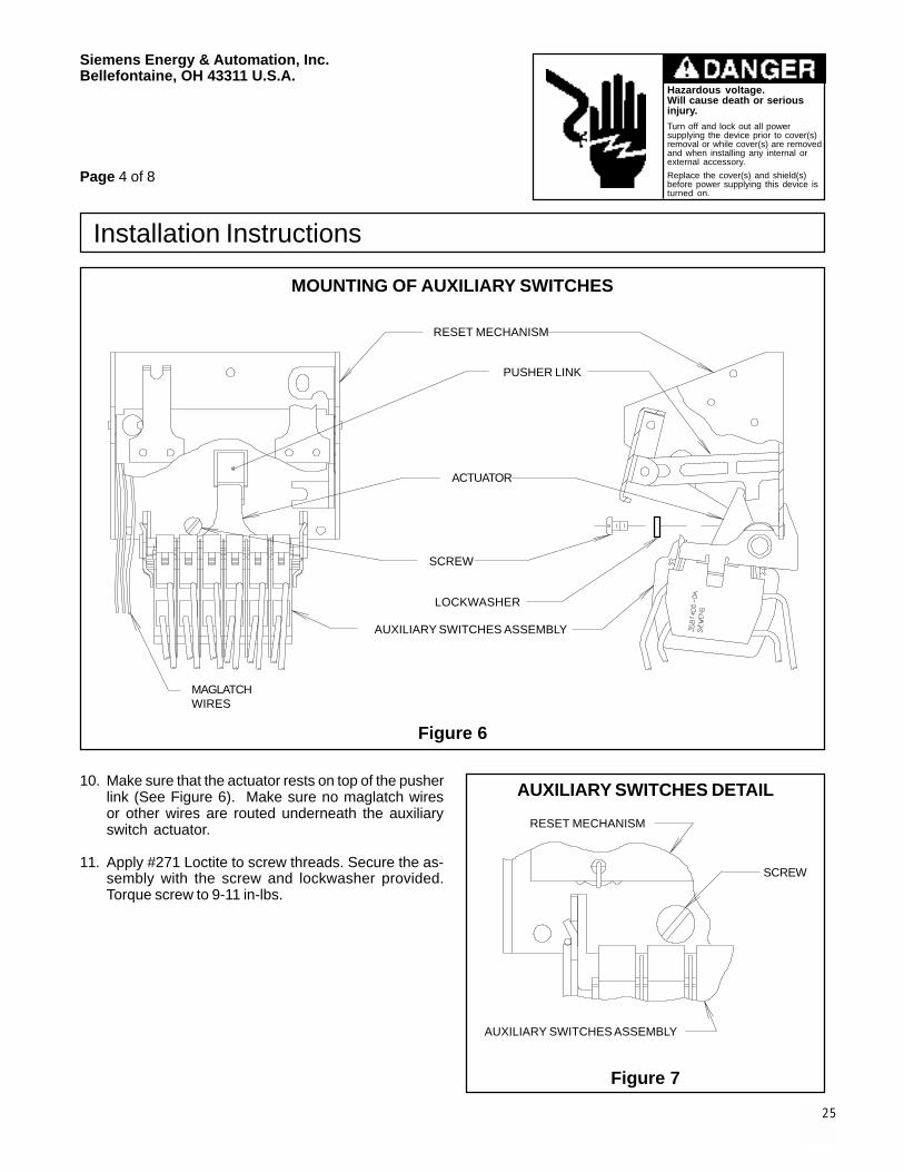
AUXILIARY SWITCHES DETAIL10. Make sure that the actuator rests on top of the pusherlink (See Figure 6). Make sure no maglatch wiresor other wires are routed underneath the auxiliaryswitch actuator.
11. Apply #271 Loctite to screw threads. Secure the as-sembly with the screw and lockwasher provided.Torque screw to 9-11 in-lbs.
MAGLATCHWIRES
RESET MECHANISM
PUSHER LINK
ACTUATOR
SCREW
AUXILIARY SWITCHES ASSEMBLY
RESET MECHANISM
SCREW
AUXILIARY SWITCHES ASSEMBLY
LOCKWASHER
25

26

27
Siemens Energy & Automation, Inc.Bellefontaine, OH 43311 U.S.A.
Hazardous voltage.Will cause death or seriousinjury.Turn off and lock out all powersupplying the device prior to cover(s)removal or while cover(s) are removedand when installing any internal orexternal accessory.
Replace the cover(s) and shield(s)before power supplying this device isturned on.
Installation Instructions
Page 6 of 8
Figure 9
LABEL MOUNTING16. Replace the trip unit by pushing it onto the trip unitplug. Slide the trip unit over the support bracketpins. Secure the trip unit by replacing the mountingscrew. Torque screw to 12-14 in-lbs (See Figures 2and 3, Page 2).
17. Apply the auxiliary switches label to the side of thecover (See Figure 9). Mark the accessory label toindicate that the auxiliary switches have beeninstalled.
18. Replace the breaker cover. Check to ensure thatthe wires exit the breaker through the wire guidesand are not pinched by the breaker cover. Replacethe 8 cover screws (See Figure 1, Page 1). Torque#10 (corner) screws to 28-32 in-lbs. Torque 1/4"screws to 68-75 in-lbs.
COVER
AUXILIARYSWITCHESLABEL
ACCESSORYLABEL

28
Siemens Energy & Automation, Inc.Bellefontaine, OH 43311 U.S.A.
Hazardous voltage.Will cause death or seriousinjury.Turn off and lock out all powersupplying the device prior to cover(s)removal or while cover(s) are removedand when installing any internal orexternal accessory.
Replace the cover(s) and shield(s)before power supplying this device isturned on.
ELECTRICAL DATA FOR AUXILIARY SWITCHES
Rating Make, Break, and Continuous Current
Voltage (Amperes)Catalog Number
60 Hz AC
120 10 STDAS2 thru STDAS12
240 10 STDAS2 thru STDAS12
480 6 STDAS2 thru STDAS12
DC
24 3 STDAS2 thru STDAS12
125 .5 STDAS2 thru STDAS12
Installation Instructions
Page 7 of 8
ELECTRICAL CHECK
a. With breaker in open position (main contacts open),check for continuity on "B" contacts and for no continu-ity on "A" contacts.
b. Close breaker by moving the handle to the OFF posi-tion then to the ON position.
c. Check for continuity on "A" contacts and for no conti-nuity on "B" contacts.
d. If the auxiliary switches do not function properly dur-ing check procedure, check for incorrect installationor wiring.
19. Perform electrical check by following steps a through d.
20. Connect the terminals to the proper terminal blocklocations (See Figure 8, Page 5).

29
Siemens Energy & Automation, Inc.Bellefontaine, OH 43311 U.S.A.
Hazardous voltage.Will cause death or seriousinjury.Turn off and lock out all powersupplying the device prior to cover(s)removal or while cover(s) are removedand when installing any internal orexternal accessory.
Replace the cover(s) and shield(s)before power supplying this device isturned on.
Installation Instructions
Pc. No. 121537A01© 1997 Siemens Energy & Automation, Inc.
Page 8 of 8
AUXILIARY SWITCHES SCHEMATIC
Figure 10
AUXILIARY
SWITCH 4
AUXILIARY
SWITCH 5
AUXILIARY
SWITCH 6
AUXILIARY
SWITCH 1
AUXILIARY
SWITCH 2
AUXILIARY
SWITCH 3
NOTE: AUXILIARY SWITCH 6MUST BE OMITTED IFEITHER ELECTRONICALARM SWITCH ORLOCAL LOAD MONI-TOR RELAY IS IN-STALLED.
INTERNAL BREAKER CONNECTIONSEXTERNAL BREAKER CONNECTIONS
<RT1>
<RT2>
<RT3>
<RT4>
<RT5>
<RT6>
<RT7>
<RT8>
<RT9>
<RT10>
<RT11>
<RT12>
<RB1>
<RB2>
<RB3>
<RB4>
<RB5>
<RB6>
<RB7>
<RB8>
<RB9>
<RB10>
<RB11>
<RB12>
AUX. 4 A
AUX. 4 A
AUX. 4 B
AUX. 4 B
AUX. 5 A
AUX. 5 A
AUX. 5 B
AUX. 5 B
AUX. 6 A
AUX. 6 A
AUX. 6 B
AUX. 6 B
AUX. 1 A
AUX. 1 A
AUX. 1 B
AUX. 1 B
AUX. 2 A
AUX. 2 A
AUX. 2 B
AUX. 2 B
AUX. 3 A
AUX. 3 A
AUX. 3 B
AUX. 3 B
TO CUSTOMER'SAPPLICATIONS

30
Alarm SwitchesAlarm switches reflect the trip status of the circuit breaker.When the mechanism is tripped due to any means, includ-ing overload, short circuit, ground fault, shunt trip, or thefront panel trip button, the alarm switch changes state.
“A” or NO” Contacts:when mechanism is latched and “Off” or “On” . . . .Open when mechanism if tripped . . . . . . . . . . . . . . . . . .Closed
“B” or “NC” Contacts:when mechanism is latched and “Off” or “On” . . . . .Openwhen mechanism is tripped . . . . . . . . . . . . . . . . . .Closed
The auxiliary switches are installed on the left side of themechanism.
To install the alarm switches, first remove the front cover(see page 14).
Follow these steps to install the alarm switches.
1. Slide insulating barrier onto rail.2. Clip one switch onto rail.3. Slide second insulating barrier onto rail.4. Clip second switch onto rail.
5. Install self-adhesive wire retainers and route wires as shown.
6. Connect the wires to the terminal strip according to the labels on the wires (LT1-LT4).
7. Replace the front cover.
Installation InstructionsTrip Alarm Switches
WARNINGInstall all accessories with the breaker“Tripped.”
To avoid injury or damage to equipment,do not install accessories with breaker in a“Closed” position.

31
SAFETY INSTRUCTIONS
Siemens Energy & Automation, Inc.Bellefontaine, OH 43311 U.S.A.
Installation Instructions
Hazardous voltage.Will cause death or seriousinjury.Turn off and lock out all powersupplying the device prior to cover(s)removal or while cover(s) are removedand when installing any internal orexternal accessory.Replace the cover(s) and shield(s)before power supplying this device isturned on.
NOTE: These instructions outline the recommendedinstallation procedure.
Tools Required: 1/4” flat blade screwdriver, 1/4” screwstarter (magnetic or clip), #2 phillips screwdriver,#3 phillips screwdriver.
Item: Shunt Trip Accessory
For use with: Siemens' Circuit Breakers or Molded Case Switches
MOUNTING OF SHUNT TRIP ASSEMBLY
1. Accessory installation should be completed before thebreaker is mounted and connected. If the breaker isinstalled turn off and lock out all power supplyingthe circuit breaker prior to cover removal or whilecover is removed. For ease of installation, it is highlyrecommended that the breaker be disconnected andremoved from the panel or the enclosure.
REMOVAL OF BREAKER COVER
Figure 1
COVER
BREAKER
TRIP UNIT
(4) #10 SCREWS
(4) 1/4" SCREWS
SHUNT TRIP ACCESSORY LABEL
WIRE GUIDE
Type: STD62000, STD62500, STD63200, SHTD62000,SHTD62500, SHTD63200, SHHTD62000,SHHTD62500,SHHTD63200, TD62000, TD62500, and TD63200
Cat. No.: STDST12, STDST24, STDST48, STDST120,STDST125, STDST240, STDST480
Page 1 of 9
Mechanical Hazard.Mechanism can cause severeinjury when cover is removed.
Before removing covertrip device by pushing"Push - To - Trip" button.
"PUSH - TO - TRIP" BUTTON

Siemens Energy & Automation, Inc.Bellefontaine, OH 43311 U.S.A.
Hazardous voltage.Will cause death or seriousinjury.Turn off and lock out all powersupplying the device prior to cover(s)removal or while cover(s) are removedand when installing any internal orexternal accessory.
Replace the cover(s) and shield(s)before power supplying this device isturned on.
Installation Instructions
REMOVAL OF TRIP UNIT REMOVAL OF TRIP UNIT
Figure 3
5. Remove the trip unit retaining screw (See Figure 2).
6. Slide the trip unit up to clear the support bracketpins (See Figure 2).
7. Remove the trip unit by pulling it off the trip unit plug(See Figure 3).
Page 2 of 9
Figure 2
TRIP UNIT
RETAININGSCREW
SLIDEUP
SUPPORT BRACKET PINS
BREAKER
BREAKER
TRIP UNIT
TRIP UNITPLUG
RESETMECHANISM
SUPPORT BRACKET PINS
2. Trip breaker by pushing the "Push-to-Trip" button.
3. To install the shunt trip assembly the breaker coverand trip unit must first be removed.
4. Remove the breaker cover by removing the (4) #10Phillips head screws at the corners and the (4) 1/4"Phillips head screws in recesses of the cover (SeeFigure 1, Page 1).
WASHER
32

33
Siemens Energy & Automation, Inc.Bellefontaine, OH 43311 U.S.A.
Hazardous voltage.Will cause death or seriousinjury.Turn off and lock out all powersupplying the device prior to cover(s)removal or while cover(s) are removedand when installing any internal orexternal accessory.
Replace the cover(s) and shield(s)before power supplying this device isturned on.
8. After the breaker cover and trip unit are removedlocate the reset mechanism (See Figure 4, below,and Figure 3, Page 2).
9. Remove the rubber band from the shunt trip assem-bly. Be careful not to drop and damage the plunger.
MOUNTING OF SHUNT TRIP ASSEMBLY
Figure 4
Installation Instructions
RESET MECHANISM
#6-32 SEMS SCREW
SHUNT TRIP
#4-40 SCREWS
MIDBARRIER
TO LT6, LT7,AND LT8
INSULATOR
"B" SWITCH
Page 3 of 9
34
Siemens Energy & Automation, Inc.Bellefontaine, OH 43311 U.S.A.
Hazardous voltage.Will cause death or seriousinjury.Turn off and lock out all powersupplying the device prior to cover(s)removal or while cover(s) are removedand when installing any internal orexternal accessory.
Replace the cover(s) and shield(s)before power supplying this device isturned on.
Installation Instructions
Page 4 of 9
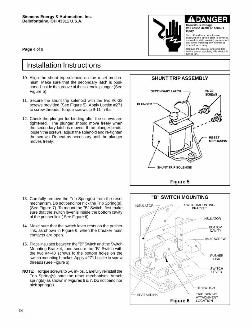
10. Align the shunt trip solenoid on the reset mecha-nism. Make sure that the secondary latch is posi-tioned inside the groove of the solenoid plunger (SeeFigure 5).
11. Secure the shunt trip solenoid with the two #6-32screws provided (See Figure 5). Apply Loctite #271to screw threads. Torque screws to 9-11 in-lbs.
12. Check the plunger for binding after the screws aretightened. The plunger should move freely whenthe secondary latch is moved. If the plunger binds,loosen the screws, adjust the solenoid and re-tightenthe screws. Repeat as necessary until the plungermoves freely.
SHUNT TRIP ASSEMBLY
Figure 5
"B" SWITCH MOUNTING
Figure 6
13. Carefully remove the Trip Spring(s) from the resetmechanism. Do not bend nor nick the Trip Spring(s).(See Figure 7). To mount the "B" Switch, first makesure that the switch lever is inside the bottom cavityof the pusher link ( See Figure 6).
14. Make sure that the switch lever rests on the pusherlink, as shown in Figure 6, when the breaker maincontacts are open.
15. Place insulator between the "B" Switch and the SwitchMounting Bracket, then secure the "B" Switch withthe two #4-40 screws to the bottom holes on theswitch mounting bracket. Apply #271 Loctite to screwthreads (See Figure 6).
NOTE: Torque screws to 5-6 in-lbs. Carefully reinstall theTrip Spring(s) onto the reset mechanism. Attachspring(s) as shown in Figures 6 & 7. Do not bend nornick spring(s).
#4-40 SCREW
PUSHERLINK
SWITCHLEVER
"B" SWITCH
HEAT SHRINK
BOTTOMCAVITY
INSULATOR
SWITCH MOUNTINGBRACKET
#6-32SCREWS
INSULATOR
TRIP SPRINGATTACHMENTLOCATION
SHUNT TRIP SOLENOID
PLUNGER
SECONDARY LATCH
RESETMECHANISM
35
Siemens Energy & Automation, Inc.Bellefontaine, OH 43311 U.S.A.
Hazardous voltage.Will cause death or seriousinjury.Turn off and lock out all powersupplying the device prior to cover(s)removal or while cover(s) are removedand when installing any internal orexternal accessory.
Replace the cover(s) and shield(s)before power supplying this device isturned on.
Installation Instructions
Page 5 of 9
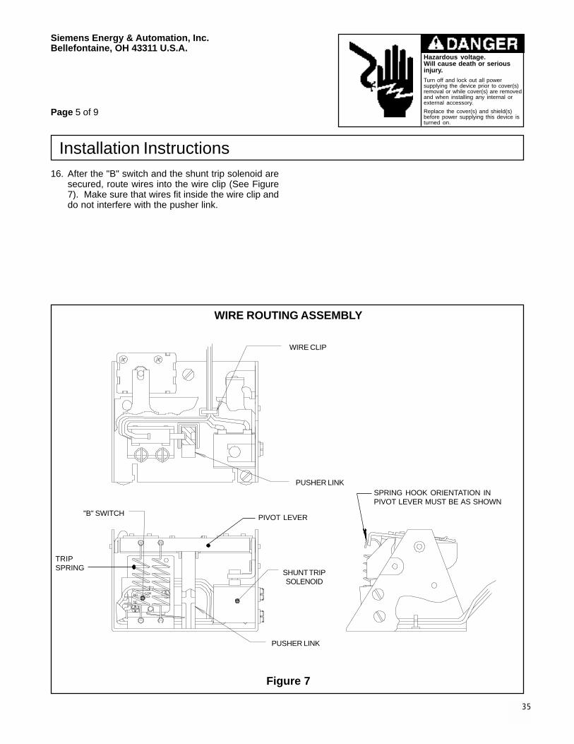
16. After the "B" switch and the shunt trip solenoid aresecured, route wires into the wire clip (See Figure7). Make sure that wires fit inside the wire clip anddo not interfere with the pusher link.
WIRE ROUTING ASSEMBLY
Figure 7
WIRE CLIP
PUSHER LINK
SHUNT TRIPSOLENOID
PUSHER LINK
"B" SWITCH PIVOT LEVER
TRIPSPRING
SPRING HOOK ORIENTATION INPIVOT LEVER MUST BE AS SHOWN

36
Siemens Energy & Automation, Inc.Bellefontaine, OH 43311 U.S.A.
Hazardous voltage.Will cause death or seriousinjury.Turn off and lock out all powersupplying the device prior to cover(s)removal or while cover(s) are removedand when installing any internal orexternal accessory.
Replace the cover(s) and shield(s)before power supplying this device isturned on.
Installation Instructions
Page 6 of 9
17. Add first and second cable tie mount and cable tieto midbarrier (See Figure 8). Do not tighten cableties until the shunt trip installation is completed.
WIRE ROUTING ASSEMBLY
CABLE TIE MOUNTWIRES
MIDBARRIER
SHUNT TRIP
"B" SWITCH
Figure 8
CABLE TIE

37
Siemens Energy & Automation, Inc.Bellefontaine, OH 43311 U.S.A.
Hazardous voltage.Will cause death or seriousinjury.Turn off and lock out all powersupplying the device prior to cover(s)removal or while cover(s) are removedand when installing any internal orexternal accessory.
Replace the cover(s) and shield(s)before power supplying this device isturned on.
Installation Instructions
Page 7 of 9
18. Add third and fourth cable tie mount and cable tie(See Figure 10).
19. Route wires through the wire guide on the midbarrier(See Figure 9).
20. Eliminate excess slack in wires. Tighten cable ties.
21. Replace the trip unit by pushing it onto the trip unitplug. Slide the trip unit over the support bracketpins. Secure the trip unit by replacing the mountingscrew. Torque screw to 12-14 in-lbs (See Figures 2and 3, Page 2).
22. Apply the shunt trip accessory label to the left side ofthe breaker cover (See Figure 1, Page 1). Mark theaccessory label on the right side of the cover to indi-cate that the shunt trip has been installed.
WIRE GUIDE DETAIL
Figure 9
WIRE ROUTING ASSEMBLY
Figure 10
LT8
CABLE TIE
CABLE TIE MOUNT
WIRE TERMINALLT7
LT6
CABLE TIE MOUNT
WIRES
CABLE TIEMOUNT
WIRE GUIDE
CABLE TIE
38
Siemens Energy & Automation, Inc.Bellefontaine, OH 43311 U.S.A.
Hazardous voltage.Will cause death or seriousinjury.Turn off and lock out all powersupplying the device prior to cover(s)removal or while cover(s) are removedand when installing any internal orexternal accessory.
Replace the cover(s) and shield(s)before power supplying this device isturned on.
Installation Instructions
Page 8 of 9
23. Replace the breaker cover. Check to ensure thatwires exit the breaker through the wire guide andare not pinched by the breaker cover. Replace the8 cover screws (See Figure 1, Page 1). Torque #10(corner) screws to 28-32 in-lbs. Torque 1/4" screwsto 68-75 in-lbs.
24. Perform electrical check by following steps a through d.
25. Connect the terminals to the proper terminal blocklocations (See Figure 10, Page 7).
ELECTRICAL CHECK
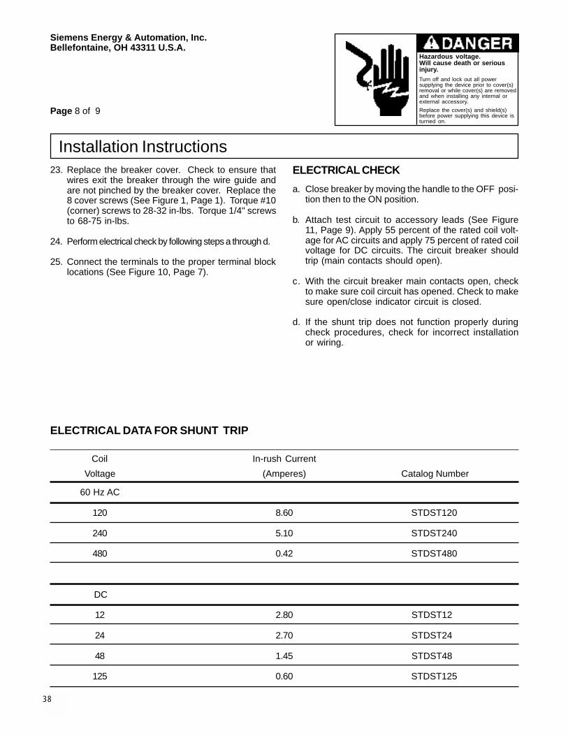
ELECTRICAL DATA FOR SHUNT TRIP
Coil In-rush Current
Voltage (Amperes) Catalog Number
60 Hz AC
120 8.60 STDST120
240 5.10 STDST240
480 0.42 STDST480
DC
12 2.80 STDST12
24 2.70 STDST24
48 1.45 STDST48
125 0.60 STDST125
a. Close breaker by moving the handle to the OFF posi-tion then to the ON position.
b. Attach test circuit to accessory leads (See Figure11, Page 9). Apply 55 percent of the rated coil volt-age for AC circuits and apply 75 percent of rated coilvoltage for DC circuits. The circuit breaker shouldtrip (main contacts should open).
c. With the circuit breaker main contacts open, checkto make sure coil circuit has opened. Check to makesure open/close indicator circuit is closed.
d. If the shunt trip does not function properly duringcheck procedures, check for incorrect installationor wiring.

39
Siemens Energy & Automation, Inc.Bellefontaine, OH 43311 U.S.A.
Hazardous voltage.Will cause death or seriousinjury.Turn off and lock out all powersupplying the device prior to cover(s)removal or while cover(s) are removedand when installing any internal orexternal accessory.
Replace the cover(s) and shield(s)before power supplying this device isturned on.
Installation Instructions
SHUNT TRIP SCHEMATIC
INTERNAL BREAKER CONNECTIONS
SHUNT TRIPCOIL
NC <ST>
NO
COM
+ -CONTROL POWER
EXTERNAL BREAKER CONNECTIONS
<LT6> COIL +
<LT7> REMOTE OPEN-CLOSED INDICATION
<LT8> COIL - (COMMON)
NOTE: SWITCH SHOWN WITH BREAKER MAIN CONTACTS OPEN
"B" TYPECLEARING
SWITCH
Figure 11
Pc. No. 121535A01© 1997 Siemens Energy & Automation, Inc.
Page 9 of 9
40
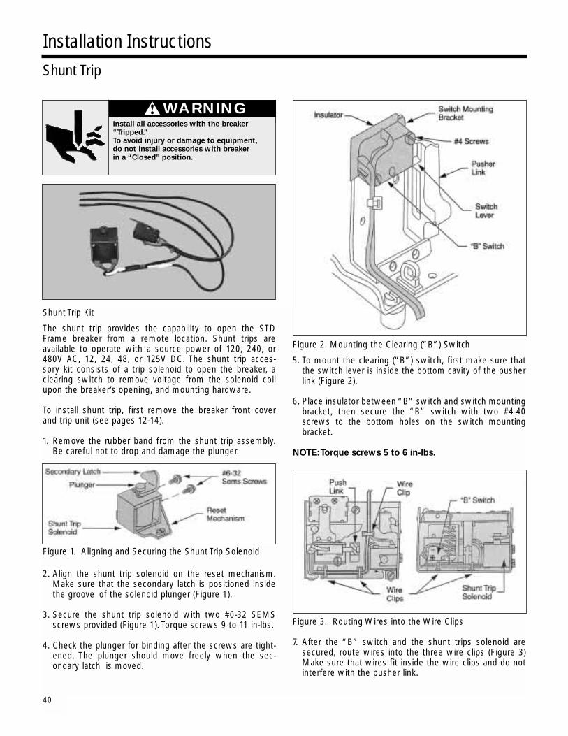
Shunt Trip Kit
The shunt trip provides the capability to open the STDFrame breaker from a remote location. Shunt trips are available to operate with a source power of 120, 240, or 480V AC, 12, 24, 48, or 125V DC. The shunt trip acces-sory kit consists of a trip solenoid to open the breaker, a clearing switch to remove voltage from the solenoid coil upon the breaker’s opening, and mounting hardware.
To install shunt trip, first remove the breaker front cover and trip unit (see pages 12-14).
1. Remove the rubber band from the shunt trip assembly. Be careful not to drop and damage the plunger.
Figure 1. Aligning and Securing the Shunt Trip Solenoid
2. Align the shunt trip solenoid on the reset mechanism. Make sure that the secondary latch is positioned inside the groove of the solenoid plunger (Figure 1).
3. Secure the shunt trip solenoid with two #6-32 SEMS screws provided (Figure 1). Torque screws 9 to 11 in-lbs.
4. Check the plunger for binding after the screws are tight-ened. The plunger should move freely when the sec-ondary latch is moved.
Figure 2. Mounting the Clearing (“B”) Switch
5. To mount the clearing (“B”) switch, first make sure that the switch lever is inside the bottom cavity of the pusher link (Figure 2).
6. Place insulator between “B” switch and switch mounting bracket, then secure the “B” switch with two #4-40 screws to the bottom holes on the switch mounting bracket.
NOTE:Torque screws 5 to 6 in-lbs.
Figure 3. Routing Wires into the Wire Clips
7. After the “B” switch and the shunt trips solenoid are secured, route wires into the three wire clips (Figure 3) Make sure that wires fit inside the wire clips and do not interfere with the pusher link.
Installation InstructionsShunt Trip
WARNINGInstall all accessories with the breaker“Tripped.”To avoid injury or damage to equipment,do not install accessories with breakerin a “Closed” position.

41
Figure 4. Routing of Wires
8. Route all wires between wire shield and mid-barrier. Make sure to route the wires toward the bottom of the trough, so that the wires fit into the mid-barrier trough (Figure 4).
Figure 5. Location of Cable Tie Mounts and Cable Tie
9. Add cable tie mounts and cable tie as directed in accessory instructions (Figure 5).
10. Replace trip unit and breaker front cover (pages 13-14), being careful not to pinch wire leads routed to sec-ondary disconnects or terminal block.
Installation InstructionsShunt Trips
WARNINGInstall all accessories with the breaker“Tripped.”To avoid injury or damage to equipment,do not install accessories with breakerin a “Closed” position.
Figure 6. Location of Shunt Trip Accessory Label
11. Apply shunt trip accessory label to side of the breaker cover (Figure 6). Mark the label that is on the opposite side of the cover to indicate that the shunt trip has been installed.

42
Shunt Trip Installation
Installation InstructionsShunt Trip Schematic Layout
Secondary Latch
Insert Plunger Groove Into Fork Of Secondary Latch (See Detail B, Below). Check For Binding After Tightening #8 Screws By Pressing Down On Top Of Plunger To Operate Secondary Latch.
Insulated Terminal (3)
MidbarrierNote: Mechanism Not Shown For Clarity.
Cable Tie
Wire Guide
#4-40 Nylok Screw
Shunt Trip Assembly (121302 K1-K7)
Cable Tie Mount
#8-32 Sems Screw
Cable Tie
Cable Tie Mount
Cable Tie
Cable Tie Mount
Hold-in Current Catalog Number (Amperes) Operating Voltage
DST12 2.50A 12V DCDST24 20.00A 24V DCDST48 10.30A 48V DCDST125 3.60A 125V DCDST120 9.40A 120V ACDST240 0.41A 240V ACDST480 0.35A 480V AC
Shunt Trip Ratings
WARNINGInstall all accessories with the breaker“Tripped.”To avoid injury or damage to equipment,do not install accessories with breakerin a “Closed” position.

43
Siemens Energy & Automation, Inc.Bellefontaine, OH 43311 U.S.A.
SAFETY INSTRUCTIONS
Mechanical Hazard.Mechanism can cause severeinjury when cover is removed.
Before removing covertrip device by pushing"Push - To - Trip" button.
Hazardous voltage.Will cause death or seriousinjury.Turn off and lock out all powersupplying the device prior to cover(s)removal or while cover(s) are removedand when installing any internal orexternal accessory.Replace the cover(s) and shield(s)before power supplying this device isturned on.
Installation Instructions
Table 1
STD20TLI STD25TLI STD32TLISTD20TLS STD25TLS STD32TLSSTD20TLSI STD25TLSI STD32TLSISTD20TLIG STD25TLIG STD32TLIGSTD20TLSG STD25TLSG STD32TLSGSTD20TLSIG STD25TLSIG STD32TLSIG
REMOVAL OF BREAKER COVER
WIRE GUIDE
1/4" SCREWS
#10 SCREWS
COVER
TRIP UNIT
BREAKER
Figure 1
BREAKER LABEL
“PUSH - TO - TRIP” BUTTON
Item: Electronic Bell Alarm or Display Module Relay
For use with: Siemens' STD Trip Units (See Table 1)
Cat. No.: STDBA24, STDBA48, STDBA120, STDBA125 orSTDDMR24, STDDMR48, STDDMR120, STDDMR125
Page 1 of 4
NOTE: These instructions outline the recommendedinstallation procedure.
STD20TLI STD25TLI STD32TLISTD20TLS STD25TLS STD32TLSSTD20TLSI STD25TLSI STD32TLSISTD20TLIG STD25TLIG STD32TLIGSTD20TLSG STD25TLSG STD32TLSGSTD20TLSIG STD25TLSIG STD32TLSIGSTD20TMLI STD25TMLI STD32TMLI
MOUNTING OF BELL ALARM OR DISPLAYMODULE RELAY1. Accessory installation should be completed before the
breaker is mounted and connected. If the breaker isinstalled turn off and lock out all power supplyingthe circuit breaker prior to cover removal or whilecover is removed. For ease of installation, it is highlyrecommended that the breaker be disconnected andremoved from the panel or the enclosure.
Electronic Bell Alarm works with Trip Unit Cat. No.STDBAxxx
123456789012345678901234567890121234567890123456789012345678901212345678901234567890123456789012345678901212345678901234567890123456789012123456789012345678901234567890123456789012123456789012345678901234567890121234567890123456789012345678901234567890121234567890123456789012345678901212345678901234567890123456789012345678901212345678901234567890123456789012123456789012345678901234567890123456789012123456789012345678901234567890121234567890
Display Module Relay works with Trip Unit Cat. No.STDDMRxxx
44
Siemens Energy & Automation, Inc.Bellefontaine, OH 43311 U.S.A.
Hazardous voltage.Will cause death or seriousinjury.Turn off and lock out all powersupplying the device prior to cover(s)removal or while cover(s) are removedand when installing any internal orexternal accessory.
Replace the cover(s) and shield(s)before power supplying this device isturned on.
Installation Instructions
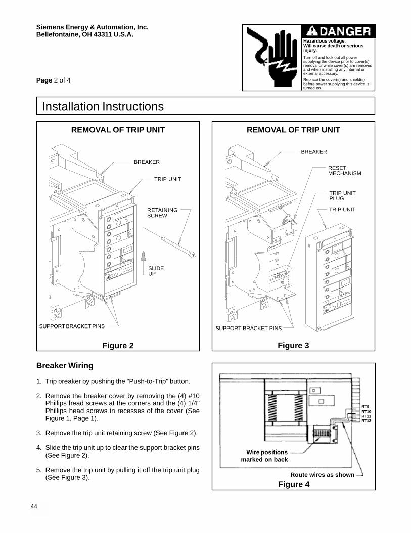
Breaker Wiring
1. Trip breaker by pushing the "Push-to-Trip" button.
2. Remove the breaker cover by removing the (4) #10Phillips head screws at the corners and the (4) 1/4"Phillips head screws in recesses of the cover (SeeFigure 1, Page 1).
3. Remove the trip unit retaining screw (See Figure 2).
4. Slide the trip unit up to clear the support bracket pins(See Figure 2).
5. Remove the trip unit by pulling it off the trip unit plug(See Figure 3).
Page 2 of 4
Figure 4
REMOVAL OF TRIP UNIT
Figure 2
RETAININGSCREW
SLIDEUP
SUPPORT BRACKET PINS
BREAKER
REMOVAL OF TRIP UNIT
Figure 3
BREAKER
TRIP UNIT
TRIP UNITPLUG
RESETMECHANISM
SUPPORT BRACKET PINS
TRIP UNIT
Wire positionsmarked on back
Route wires as shown
RT9RT10RT11RT12

45
Siemens Energy & Automation, Inc.Bellefontaine, OH 43311 U.S.A.
Hazardous voltage.Will cause death or seriousinjury.Turn off and lock out all powersupplying the device prior to cover(s)removal or while cover(s) are removedand when installing any internal orexternal accessory.
Replace the cover(s) and shield(s)before power supplying this device isturned on.
Installation Instructions
Page 3 of 4
6. With a small screwdriver press in the tab on the rightside of the 36-pin trip unit plug and release it from themounting bracket. Connect the 2 short wires on thisaccessory to the trip unit 36-pin plug. The wire la-beled #22 connects to pin hole #22 and the otherwire, which is not labeled, connects to pin #1 for theElectronic Bell Alarm or pin #4 for the Display Mod-ule Relay. Route wires under the reset mechanismand out the top wire guide in the midbarrier. Connectwires labeled RT9 through RT12 to the Right Top Ter-minal Block as marked. Refer to Figures 3 and 4,Page 2, and Figure 5 for wiring connections and rout-ing. Snap the 36-pin plug back into the bracket, tak-ing care to orient it properly.
7. Mount the Bell Alarm or Display Module Relay to thetrip unit bracket as shown in Figure 6, Page 4, with 2screws and lockwashers that are provided.
Figure 5
8. Bundle wires using the wire ties provided and routethem as shown in Figure 4, Page 2.
9. Replace trip unit by pushing it onto the trip unit plug.Slide trip unit over the support bracket pins. Securethe trip unit by replacing the mounting screw. Torquescrew to 6-8 in-lbs (See Figures 2 and 3, Page 2).
10. Replace the breaker cover. Check to ensure thatwires exit the breaker through the wire guide and arenot pinched by the breaker cover. Replace the 8 coverscrews (See Figure 1, Page 1). Torque #10 (corner)screws to 28-32 in-lbs. Torque 1/4" screws to 68-75in-lbs.
11. Apply label to left side of circuit breaker cover.
ALARM RESET SWITCH
ELECTRONIC BELL ALARM
DISPLAY MODULE RELAY
TRIP UNIT
INTERNALBREAKERCONNECTIONS
EXTERNALCONNECTIONS
NOTE: ELECTRONIC BELL ALARM,DISPLAY MODULE RELAY, ANDREMOTE INDICATOR PANEL AREMUTUALLY EXCLUSIVE. NOCOMBINATION OF THESE DEVICESARE PERMITTED.
CONTROLPOWER
CONTROLPOWER
ALARM
ALARM
<RT9>
<RT10>
<RT11>
<RT12>
<RT9>
<RT10>
<RT11>
<RT12>

46
Siemens Energy & Automation, Inc.Bellefontaine, OH 43311 U.S.A.
Hazardous voltage.Will cause death or seriousinjury.Turn off and lock out all powersupplying the device prior to cover(s)removal or while cover(s) are removedand when installing any internal orexternal accessory.
Replace the cover(s) and shield(s)before power supplying this device isturned on.
Installation InstructionsHardware List: QuantityMOUNTING SCREWS 2LOCKWASHER 2WIRE TIES 3LABEL, BREAKER ACCESSORY 1
WIRING
All external wiring beyond the terminal block (See Figure5, Page 3) must be 18 AWG. This accessory is availablein four different control power ratings: 24VDC, 48VDC,125VDC, and 120VAC. Connect the correct control powerto terminals RT9 and RT12 using the correct polarity asshown in Figure 5, Page 3.
The two relay outputs are RT10 which is N.O. and RT11which is N.C. These contacts are rated 60VA-1.25A-150VDC/200VAC MAX.
BELL ALARM RELAY FUNCTIONS
The relay outputs on this device can be used for wiring toremote indicators.
The Bell Alarm will latch the relay output when it receivesa trip signal from the trip unit. Resetting the Bell Alarm isdone by manually pushing the user-installed reset switchas shown in Figure 5, Page 3.
DISPLAY MODULE RELAY FUNCTIONS
The relay outputs on this device can be used for wiring toremote indicators.
The Display Module Relay works in conjunction with theDisplay Module (Cat. No. STDDM) mounted in the lowerpart of the trip unit. The front of this Display Module hasa control switch to select alarm set points of 60, 70, 80,90, or 100% of the continuous ampere rating of the cir-cuit breaker. When the current level exceeds the switchsetting a signal is sent to the Display Module Relay caus-ing the contacts to close. The contacts remain closedonly for the duration of the signal and do not latch closed.
GROUND FAULT SENSING AND RELAYINGSYSTEM
When used with a Ground Fault Monitor Module (Cat.No. STDGFM), the Display Module Relay may be usedas a Ground Fault Sensing and Relaying equipment sys-tem. For more information see the Ground Fault Sens-ing and Relaying Equipment instructions (Dwg. No.121532).
NOTE: If the circuit breaker is powered up without theModule installed, the alarm will be set to its “ON”state.
Figure 6
Pc. No. 121534A01© 1997 Siemens Energy & Automation, Inc.
Page 4 of 4
TRIP UNIT CONNECTOR
ELECTRONIC BELL ALARM ORDISPLAY MODULE RELAY
SCREW(PROVIDED)
LOCKWASHER(PROVIDED)
TRIPUNIT BRACKET
MOUNTING OFELECTRONIC BELL ALARMOR DISPLAY MODULE RELAY

47
SAFETY INSTRUCTIONS
Siemens Energy & Automation, Inc.Bellefontaine, OH 43311 U.S.A.
Hazardous voltage.Will cause death or seriousinjury.Turn off and lock out all powersupplying the device prior to cover(s)removal or while cover(s) are removedand when installing any internal orexternal accessory.Replace the cover(s) and shield(s)before power supplying this device isturned on.
Installation Instructions
Mechanical Hazard.Mechanism can cause severeinjury when cover is removed.
Before removing covertrip device by pushing"Push - To - Trip" button.
NOTE: These instructions outline the recommendedinstallation procedure.
Item: Remote Indicator Panel
For use with: Siemens' STD Trip Units (See Table 1)
Cat. No.: STDRIP120
Page 1 of 6
���������Table 1 - Trip Units
STD20TLI STD25TLI STD32TLISTD20TLS STD25TLS STD32TLSSTD20TLSI STD25TLSI STD32TLSISTD20TLIG STD25TLIG STD32TLIGSTD20TLSG STD25TLSG STD32TLSGSTD20TLSIG STD25TLSIG STD32TLSIG
MOUNTING OF REMOTE INDICATOR PANEL1. Accessory installation should be completed before the
breaker is mounted and connected. If the breaker isinstalled turn off and lock out all power supplyingthe circuit breaker prior to cover removal or whilecover is removed. For ease of installation, it is highlyrecommended that the breaker be disconnected andremoved from the panel or the enclosure.
REMOVAL OF BREAKER COVER
Figure 1
COVER
BREAKER
TRIP UNIT
(4) #10 SCREWS
(4) 1/4" SCREWS
BREAKER LABEL
WIRE GUIDE
"PUSH - TO - TRIP" BUTTON

48
Siemens Energy & Automation, Inc.Bellefontaine, OH 43311 U.S.A.
Hazardous voltage.Will cause death or seriousinjury.Turn off and lock out all powersupplying the device prior to cover(s)removal or while cover(s) are removedand when installing any internal orexternal accessory.
Replace the cover(s) and shield(s)before power supplying this device isturned on.
Installation Instructions
Breaker Wiring1. The wires included in the plastic parts bag must be
installed inside the breaker. These wires connect thetrip unit to the terminal block mounted externally onthe circuit breaker.
2. Trip breaker by pushing the "Push-to-Trip" button.
3. Remove the breaker cover by removing the (4) #10Phillips head screws at the corners and the (4) 1/4"Phillips head screws in recesses of the cover (SeeFigure 1, Page 1).
4. Remove the trip unit retaining screw (See Figure 2).
5. Slide the trip unit up to clear the support bracket pins(See Figure 2).
6. Remove the trip unit by pulling it off the trip unit plug(See Figure 3).
7. With a small screwdriver press in the tab on the rightside of the 36-pin trip unit plug and release it from themounting bracket. Connect the wires provided be-tween the trip unit 36-pin plug and the external termi-nal block. Refer to Figures 4 and 5, Page 3, for wirerouting and connections. Snap the 36-pin plug backinto the bracket, taking care to orient it properly.
8. Bundle wires using the wire ties provided and routethem as shown in Figure 4, Page 3 .
9. Replace the trip unit by pushing it onto the trip unitplug. Slide the trip unit over the support bracket pins.Secure the trip unit by replacing the mounting screw.Torque screw to 6-8 in-lbs (See Figures 2 and 3).
10. Replace the breaker cover. Check to ensure thatwires exit the breaker through the wire guide and arenot pinched by the breaker cover. Replace the 8 coverscrews (See Figure 1, Page 1). Torque #10 (corner)screws to 28-32 in-lbs. Torque 1/4" screws to 68-75in-lbs.
Page 2 of 6
REMOVAL OF TRIP UNIT
Figure 2
RETAININGSCREW
SLIDEUP
SUPPORT BRACKET PINS
BREAKER
REMOVAL OF TRIP UNIT
Figure 3
BREAKER
TRIP UNIT
TRIP UNITPLUG
RESETMECHANISM
SUPPORT BRACKET PINS
TRIP UNIT
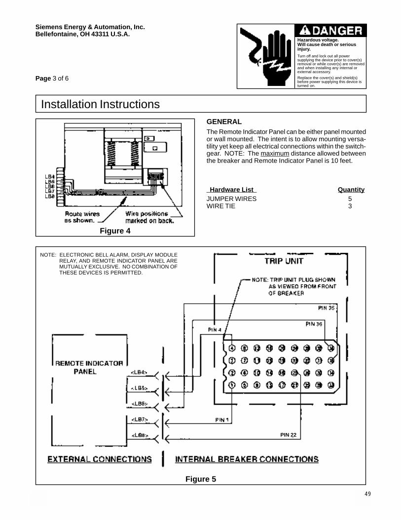
49
Siemens Energy & Automation, Inc.Bellefontaine, OH 43311 U.S.A.
Hazardous voltage.Will cause death or seriousinjury.Turn off and lock out all powersupplying the device prior to cover(s)removal or while cover(s) are removedand when installing any internal orexternal accessory.
Replace the cover(s) and shield(s)before power supplying this device isturned on.
Installation InstructionsGENERALThe Remote Indicator Panel can be either panel mountedor wall mounted. The intent is to allow mounting versa-tility yet keep all electrical connections within the switch-gear. NOTE: The maximum distance allowed betweenthe breaker and Remote Indicator Panel is 10 feet.
Hardware List QuantityJUMPER WIRES 5WIRE TIE 3
Figure 4
NOTE: ELECTRONIC BELL ALARM, DISPLAY MODULERELAY, AND REMOTE INDICATOR PANEL AREMUTUALLY EXCLUSIVE. NO COMBINATION OFTHESE DEVICES IS PERMITTED.
Figure 5
Page 3 of 6
PIN 22

50
Siemens Energy & Automation, Inc.Bellefontaine, OH 43311 U.S.A.
Hazardous voltage.Will cause death or seriousinjury.Turn off and lock out all powersupplying the device prior to cover(s)removal or while cover(s) are removedand when installing any internal orexternal accessory.
Replace the cover(s) and shield(s)before power supplying this device isturned on.
Installation Instructions
Page 4 of 6
PANEL MOUNTINGMounting hole must be cut in panel measuring 4-1/16"wide by 6-5/8" high. Remove both flange brackets andinsert the Remote Indicator Panel through front of panel.Replace flange brackets positioned as shown in Figure6, Page 5, and slide them up tight against back of panel.Tighten the four flange bracket screws securely.
WALL MOUNTINGThis style mounting is intended for use inside switchgearhousing. Reverse flange brackets as shown in Figure 7,Page 5. Place unit on flat surface, slide brackets downeven with surface, and tighten screws. Hold unit in loca-tion desired. Mark and drill all 4 holes for a #6 screw.Mount Remote Indicator Panel with (4) #6 screws (notsupplied).
WIRINGNote that the Remote Indicator Panel terminal blocksare removable for ease of wiring. Pull them straight outto unplug, insert wires, tighten screws, then plug themback into the circuit board.
Wire Remote Indicator Panel to circuit breaker using ter-minals on left side marked LB4-LB8. Connect them tothe corresponding terminal block positions located onthe left bottom side of the breaker. These wires must be18 AWG minimum with a maximum length of 10 feet.
The 5 relay outputs located on the bottom right terminalblock of the Remote Indicator Panel (See Figure 8, Page6) may be wired to your system using 18 AWG wire. Thecontact ratings of these relays are 60VA-1.25A-150VDC/200VAC MAX.
Connect supply power to the top right terminal block ofthe Remote Indicator Panel as marked (See Figure 8,Page 6). Use the correct voltage as marked on the name-plate. Make sure the housing is grounded using the #8-32 screw provided.
RELAY FUNCTIONSThe relay outputs on this device can be used for wiringto remote indicators.
In a trip condition only one of the four relays marked G.F.(Ground Fault), S.T. (Short Time), O.L. (Over Load), orS.C. (Short Circuit) will latch and stay latched until theReset button on the front of the Remote Indicator Panelis pushed. Which relay latches is dependent on the tripcondition of the breaker.
The other relay marked M.A. (Module Alarm) does notlatch, but pulls in and drops out dependent on the switchsetting of the Module located in the trip unit. This couldbe either a Display Module or a Ground Fault MonitorModule. When the current exceeds the switch setting,relay "M.A." pulls in and when the current goes belowthe switch setting, it drops out. If a Display Module or aGround Fault Monitor Module is not used in conjunctionwith the Remote Indicator Panel, the relay "M.A." pulls inwhen the breaker is energized
GROUND FAULT SENSING ANDRELAYING SYSTEMWhen used with a Ground Fault Monitor Module (Cat.No. STDGFM) the Remote Indicator Panel may be usedas a Ground Fault Sensing and Relaying equipment sys-tem. For more information see the Ground Fault Sens-ing and Relaying Equipment instructions (Dwg. No.121532).
NOTE: If the circuit breaker is powered up withoutthe Module installed, the alarm will be set toits “ON” state.

51
Siemens Energy & Automation, Inc.Bellefontaine, OH 43311 U.S.A.
Hazardous voltage.Will cause death or seriousinjury.Turn off and lock out all powersupplying the device prior to cover(s)removal or while cover(s) are removedand when installing any internal orexternal accessory.
Replace the cover(s) and shield(s)before power supplying this device isturned on.
Installation Instructions
Page 5 of 6
PANEL MOUNT
Figure 6
WALL MOUNT
Figure 7
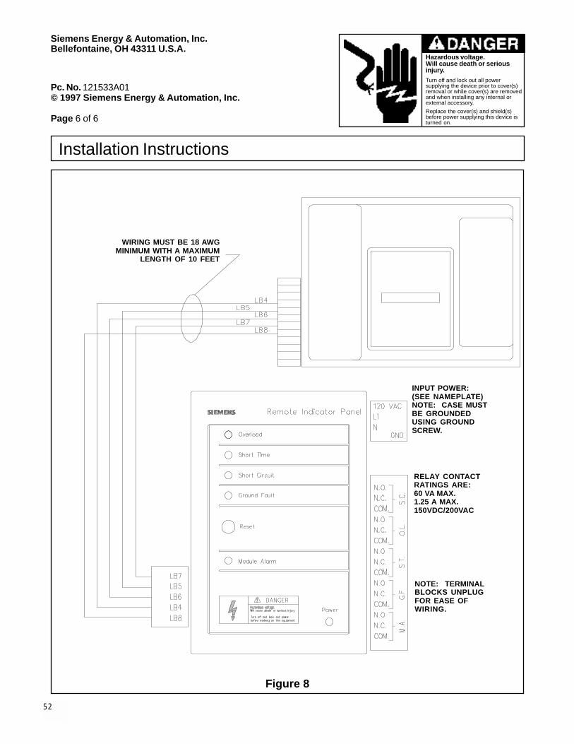
52
Siemens Energy & Automation, Inc.Bellefontaine, OH 43311 U.S.A.
Hazardous voltage.Will cause death or seriousinjury.Turn off and lock out all powersupplying the device prior to cover(s)removal or while cover(s) are removedand when installing any internal orexternal accessory.
Replace the cover(s) and shield(s)before power supplying this device isturned on.
Installation Instructions
Pc. No. 121533A01© 1997 Siemens Energy & Automation, Inc.
Page 6 of 6
WIRING MUST BE 18 AWGMINIMUM WITH A MAXIMUM
LENGTH OF 10 FEET
INPUT POWER:(SEE NAMEPLATE)NOTE: CASE MUSTBE GROUNDEDUSING GROUNDSCREW.
RELAY CONTACTRATINGS ARE:60 VA MAX.1.25 A MAX.150VDC/200VAC
NOTE: TERMINALBLOCKS UNPLUGFOR EASE OFWIRING.
Figure 8

53
Siemens Energy & Automation, Inc.Bellefontaine, OH 43311 U.S.A.© 1997 Siemens Energy & Automation, Inc.
Installation Instructions
SAFETY INSTRUCTIONS
Item: ������������������ �
For Use With: �������������� ������������������������� ����
Type: STD62000, TD62000
Cat. No.: TA6R600STD
Page 1 of 1
Pc. No. 121545A01
NOTE: These instructions outline the recommendedinstallation procedure.
Terminals have been tested per UL 486B with standardstranded cable.
MOUNTING OF PRESSURE WIRE CONNECTOR1. Accessory installation should be completed before the
breaker is mounted and connected. If the breaker isinstalled turn off and lock out all power supplyingthe circuit breaker when installing any internal orexternal accessory. For ease of installation, it ishighly recommended that the breaker be disconnectedand removed from the panel or the enclosure.
2. Attach power cables (A) to pressure wire connector(C) and torque cable set screws (B) to 375 in-lbs.
3. Mount pressure wire connectors (C) to the breakerterminals (D) with mounting bolts, Bellevillewashernuts, and Belleville washers provided. Pres-sure wire connector must be mounted in the holesclosest to the breaker case (See Figure 1). Torquemounting bolts to 375 in-lbs.
Figure 1
BREAKER
MOUNTING BOLT (3/8-16)
BELLEVILLE WASHER
BELLEVILLE WASHERNUT
CatalogNumber
Wire RangeTorque
SetScrew
MountingBolt
TA6R600STD (1-6) 250-600kcmil CU7AL
375 in-lbs. 375 in-lbs.
Hazardous voltage.Will cause death or seriousinjury.Turn off and lock out all power supplyingthe circuit breaker prior to cover(s)removal or while cover(s) are removedand when installing any internal orexternal accessory.Replace the cover(s) and shield(s)before power supplying this device isturned on.

54
Installation Instructions
Siemens Energy & Automation, Inc.Bellefontaine, Ohio 43311 U.S.A.
SAFETY INSTRUCTIONS
Hazardous voltage.Will cause death or seriousinjury.
Turn off and lock out all powersupplying the device wheninstalling any internal orexternal accessory.
��������������������������� ��������� ������������ ������������������������������������������������������������������������������� ������������ ������ ��� ���
������� ��������������� ��������������� ��������� ������������������������ ���������� �������������������������������� ���� ������ ������� �������� ��� ������ ��� � ������� �������� � ��������� ������ ������ ����� ��������� ���� �������������������� ��������������� ��� ������������������������������� ��������������������� ��� ���������� ��������� �����������!�� �������� ��"�����# ���$ ��%��!�"&'()� ���� �������� �������� * ���� !����� # ��� $ �%���*!'+�� %���*!+,�� %���*!&'(�� �%���*!&'�)����������������� ����������-(��.(�,(��/(�� ��&((�������� �� ���� ��� �������������
0�� ��� ���������������������1������� ���������� ������������* ��������������������������������� ����23$4�����
���������������������� ���������������� ��������������������������������������������������������������������������� �����������#&�)������������������������������������������ ����������� ������������������������������������ ������������������ ��� ��
��� ������������� ������ �� ������ �� �������� �� �����������������������������������1��������������������������������������������������������� ���������������� �������������� ����������� ���������������������� ����������� ������� ����� �����%���5���� ���������6�������������������������� ��
� �����������
������������* ������ �������������� ����� ����������� �� ������� �� ����������������������������� ��������������������������������������� ��������� ������ ����������������� ���� �����������������������1����������� ���� ����������������������������������7�38�7������������1�������� ���� ���� ��������� ����
Item: Display Module and Ground Fault Monitor
For use with: Siemens' STD Trip Units (See Table 1)
Cat. No.: STDDM and STDGFM
Page 1 of 3
Display Module
Present DemandMaximum Demand
IA IBIC
10090 80
70
60
Load Monitor Alarm Set Points% Continuous AmpsAmps
Figure 1
Meter
���������Table 1 - Trip Units
STD20TLI STD25TLI STD32TLISTD20TLS STD25TLS STD32TLSSTD20TLSI STD25TLSI STD32TLSISTD20TLIG STD25TLIG STD32TLIGSTD20TLSG STD25TLSG STD32TLSGSTD20TLSIG STD25TLSIG STD32TLSIG
CAUTION
Open
Breaker
before
removing
Module.

55
Siemens Energy & Automation, Inc.Bellefontaine, OH 43311 U.S.A.
Installation Instructions
Hazardous voltage.Will cause death orserious injury.
Turn off and lock out allpower supplying the devicewhen installing any internalor external accessory.
Ground Fault Monitor
The Ground Fault Monitor (GFM) is an optionalmodule that allows the user to locally monitor theground fault current and can be used in trip unitswith or without the integral ground fault protectionfunction. Trip units with the integral ground faultprotection function are identified by a "G" in thecatalog number and the presence of ground faultadjustments on the face of the trip unit. If the trip unitis equipped with ground fault protection, the GroundFault Monitor utilizes the same ground fault sensingmethod as the electronic trip unit. If the trip unit isnot equipped with ground fault protection, the GFMuses a residual ground fault sensing method. TheGround Fault Monitor works independently of thetrip unit's ground fault protection.
SettingsThere are three ground fault pickup levels offeredon the Ground Fault Monitor:"LO" equals 20 percent of the frame rating."MED" equals the average of the "LO" and "HI"pickup levels."HI" equals either the frame rating or 1200 amps,whichever is less.
The ground fault delays are divided into three fixedtime delay bands: 0.1, 0.3, and 0.5 seconds. The"MAX" setting is defined as a 1200 amp pickup and0.5 second delay.
Ground FaultMonitor
HIMED
LO
LOMED
HI
LOMEDHI
MAX
.5s
.1s .3s
Amps
Figure 2
DisplayThe Ground Fault Monitor displays the ground faultcurrent in amps. When the ground fault currentreaches a level 12 percent below the selectedpickup setting, the amps display will start to flash.When the ground fault current exceeds the selectedpickup setting, the display will flash "-OL-" for over-load and the alarm line will be set to its "ON" state.
Remote InterfaceThe Ground Fault Monitor can be utilized with aDisplay Module Relay (mounted inside the breaker)or a Remote Indicator Panel (externally mounted) toprovide a set of relay contacts for ground faultalarm. When used in conjunction with either ofthese devices and a Shunt Trip, the Ground FaultMonitor can be used as Ground Fault Sensing andRelaying equipment per U. L. 1053. For moreinformation see the Installation Instructions for theGround Fault Sensing and Relaying System (Dwg.No. 121532).
��������������� ����������������������������������� �� ������� ������ �������� ���������� ����������������������������������
Page 2 of 3
CAUTION
Open
Breaker
before
removing
Module.

56
Siemens Energy & Automation, Inc.Bellefontaine, OH 43311 U.S.A.
Installation Instructions
Hazardous voltage.Will cause death orserious injury.
Turn off and lock out allpower supplying the devicewhen installing any internalor external accessory.
Installation:NOTE: These instructions outline the recommendedinstallation procedure.
To install this device:
1. Trip breaker by pushing the "Push-to-Trip"button.
2. Remove the two sealable cover screws from theface of the trip unit.
3. Remove the clear plastic trip unit cover using ascrewdriver in the notches provided at the topand bottom of the trip unit.
4. Remove the blank module cover at the bottom ofthe trip unit. The cover snaps out.
5. Install the Ground Fault Monitor Module by press-ing both sides down into the opening until thesnap fits click, locking it in place.
6. Replace the clear cover. Make sure that theGround Fault Monitor Module switch is acces-sible through the hole on the bottom right side ofthe clear cover.
7. Install the two cover screws and seal the trip unit.
For additional information, refer to Siemens Publi-cation No. IPIM-0283A, STD Frame Breaker Infor-mation and Instruction Guide.
Figure 3
TRIP UNIT
SEALABLE COVERSCREWS
CLEAR COVER
BLANK MODULECOVER
DISPLAY ORGROUND FAULTMONITOR MODULE
Pc. No. 121531A01© 1997 Siemens Energy & Automation, Inc.
Page 3 of 3

57
SAFETY INSTRUCTIONS
Siemens Energy & Automation, Inc.Bellefontaine, OH 43311 U.S.A.
Hazardous voltage.Will cause death or seriousinjury.Turn off and lock out all power supplyingthe device prior to cover(s) removal orwhile cover(s) are removed and wheninstalling any internal or externalaccessory.Replace the cover(s) and shield(s)before power supplying this device isturned on.
Installation Instructions
Table 4 - DisplayModule Relay
STDDMR24STDDMR48STDDMR120STDDMR125
STDST12 STDST120STDST24 STDST240STDST48 STDST480STDST125
���������Table 1 - Trip Units
STD20TLI STD25TLI STD32TLISTD20TLS STD25TLS STD32TLSSTD20TLSI STD25TLSI STD32TLSISTD20TLIG STD25TLIG STD32TLIGSTD20TLSG STD25TLSG STD32TLSGSTD20TLSIG STD25TLSIG STD32TLSIG
Table 2 - Circuit Breakers
STD62000 SHTD62000 SHHTD62000STD62500 SHTD62500 SHHTD62500STD63200 SHTD63200 SHHTD63200
Item: Ground Fault Sensing & Relaying Equipment
For use with: Siemens' STD Trip Units (See Table 1)
Page 1 of 5
Figure 1
GROUND FAULT SENSING AND RELAYING:
This system will provide Class I ground fault protectionas described in UL STANDARD 1053, GROUND FAULTSENSING AND RELAYING EQUIPMENT.
System Components:UL Listed Circuit Breaker Components and AccessoryComponents1. Circuit Breakers Table 22. Trip Units Table 13. Rating Plugs Table 34. GF Monitor Module STDGFM5. Display Module Relay Table 4
or Remote Indicator Panel STDRIP1206. Shunt Trip Device Table 5
GROUND FAULT SENSING & RELAYINGEQUIPMENT
Table 3 - Rating Plugs
20STD1000 25STD1600 32STD160020STD1200 25STD2000 32STD200020STD1600 25STD2500 32STD250020STD2000 32STD3000
32STD3200
GF MONITORMODULE
RATINGPLUG
GF TYPESWITCH
DISPLAY MODULE RELAY
SHUNT TRIP DEVICE
BREAKER FRAME
TRIP UNIT
Table 5 - Shunt Trip

58
Siemens Energy & Automation, Inc.Bellefontaine, OH 43311 U.S.A.
Hazardous voltage.Will cause death or seriousinjury.Turn off and lock out all powersupplying the device prior to cover(s)removal or while cover(s) are removedand when installing any internal orexternal accessory.
Replace the cover(s) and shield(s)before power supplying this device isturned on.
Installation Instructions6. The results of this testing should be recorded on the
form provided at the end of this document or otherappropriate forms and should be available to the in-spection authority.
7. These breakers may be set for different modes of op-eration, Residual or Ground Return, as described inthe instructions supplied with the circuit breaker. Forfurther information on applications, refer to the NEMAstandards publication No. PB 2.2 Application Guidefor Ground Fault Protective Devices for Equipment.1
Test OperationGF Type Switch set to RESIDUALOutgoing Circuit Method (if trip unit does not provideground fault protection, this is the method used)
3 Phase / 3 WireUsing Figure 2, Page 4, and Illustration 1 or 2, individu-ally test breaker poles A, B, and C for proper GroundFault operation.
Each of the circuit breaker's front panel controls shouldbe set to the highest setting. Set the Ground Fault Moni-tor to the LO pickup on the .1 second delay band. Usinga low voltage current source, apply a test current equalto 50% of the rating plug value. The circuit breaker musttrip.
3 Phase / 4 WireUsing Figure 3, Page 4, and Illustration 1 or 2, individu-ally test breaker poles A, B, and C in conjunction with theproper neutral sensor for proper Ground Fault operation.
Each of the circuit breaker's front panel controls shouldbe set to the highest setting. Set the Ground Fault Moni-tor to the LO pickup on the .1 second delay band. Usinga low voltage current source, apply a test current equalto 50% of the rating plug value. The circuit breaker mustnot trip. Reduce the test current to zero.
Using a suitable means, short the X1 wire and the X2wire connections together on the Neutral Sensor. Reap-ply a test current equal to 50% of the rating plug value.The circuit breaker must trip. Reduce the test current tozero and remove the shorting means from the NeutralSensor.
Page 2 of 5
System Description:This Ground Fault Sensing & Relaying Equipment sys-tem is based on the Type STD molded case circuitbreaker. The breaker must be equipped with an elec-tronic Trip Unit and Rating Plug. The trip unit can be thetype with or without the built-in ground fault tripping func-tion. The breaker must also have a GF Monitor Module,a Shunt Trip Device, and either a Display Module Relayor Remote Indicator Panel. For a system completely en-closed within the breaker case, the internally mountedDisplay Module Relay is used. If remote cause of tripinformation is required, the Remote Indicator Panel maybe used in place of the Display Module Relay.
System Operation:The user must first set the desired ground fault pickupand delay settings on the Ground Fault Monitor Module.These settings are independent from the trip unit built-inground fault setting (if available). When a ground faultabove the selected pickup occurs, the breaker will delaybased on the module settings and when the proper timehas elapsed, issue a signal to the internal Display Mod-ule Relay or external Remote Indicator Panel. The out-put contacts of the relay can then be used to trigger theShunt Trip Device, thus tripping the circuit breaker.
Testing:General Instructions:
1. The interconnected system shall be evaluated by quali-fied personnel when initially installed. It is also rec-ommended that this be done periodically thereafter.
2. The proper location of the sensors around the bus ofthe circuit to be protected shall be determined. Thiscan be done visually with knowledge of which bus isinvolved.
3. The grounding points of the system shall be verifiedto determine that ground paths do not exist that wouldbypass the sensors.
4. The polarity of the sensor connections must agreewith the installation instructions to avoid improper op-eration.
5. A simulated test is to be done using a low voltage,high current source. This test is not intended to verifycalibration of the ground fault protection, but to verifythat it is functioning properly.

59
Siemens Energy & Automation, Inc.Bellefontaine, OH 43311 U.S.A.
Hazardous voltage.Will cause death or seriousinjury.Turn off and lock out all powersupplying the device prior to cover(s)removal or while cover(s) are removedand when installing any internal orexternal accessory.
Replace the cover(s) and shield(s)before power supplying this device isturned on.
Installation Instructions
Page 3 of 5
GF Type Switch set to GROUND RETURNGround Return Method
3 Phase / 3 Wire or 3 Phase / 4 WireUsing Figure 4, Page 4, and Illustration 1 or 2, test neu-tral sensor for proper Ground Fault operation. Each ofthe circuit breaker's front panel controls should be set tothe highest setting. Set the Ground Fault Monitor to theLO pickup on the .1 second delay band. Using a lowvoltage current source, apply a test current equal to 50%of the rating plug value. The circuit breaker must trip.
For more information:
See Siemens Publication No. IPIM-0283A, STD FrameBreaker Information and Instruction Guide, for ground faultsensing schemes and wiring schematics.
Note: Shunt Trip and Display Module must have thesame supply rating (e.g. STDDMR120 and STDST120)
Wiring Diagram for GF System using STD Display Module RelayIllustration 1
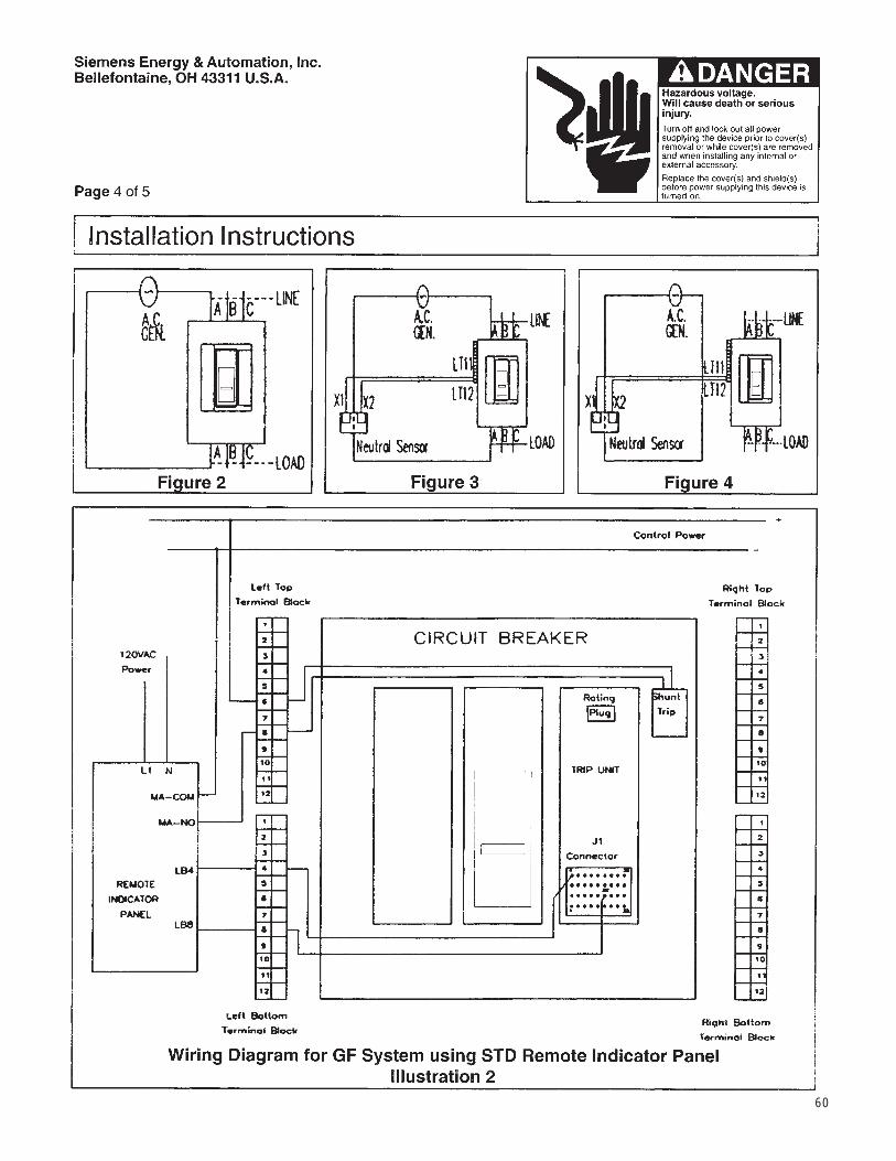
60

61
Siemens Energy & Automation, Inc.Bellefontaine, OH 43311 U.S.A.
Hazardous voltage.Will cause death or seriousinjury.Turn off and lock out all powersupplying the device prior to cover(s)removal or while cover(s) are removedand when installing any internal orexternal accessory.
Replace the cover(s) and shield(s)before power supplying this device isturned on.
Installation Instructions
Pc. No. 121532A01© 1997 Siemens Energy & Automation, Inc.
Page 5 of 5
GROUND FAULT TEST RECORD
Date Tested: ____________ Tested By: ___________
Breaker Cat. No. ______________ Location ____________________________________
Rating Plug Value _____________
Results ___________________________________________________________________________________
__________________________________________________________________________________________
__________________________________________________________________________________________
__________________________________________________________________________________________
__________________________________________________________________________________________
1NEMA PB 2.2 is available from: National Electrical Manufacturers Association2101 L. Street, N.W., Suite 300Washington, D.C. 20037
ABC
ABC

62
Siemens Energy & Automation, Inc.Bellefontaine, OH 43311 U.S.A.
Figure 3Figure 1
Figure 2
3. The white plastic cable cap should fit flush against therear of the breaker (See Figure 2). If the cable does notfit flush against the breaker, adjustments can be madewith the cable jam nuts (see Figure 2).
NOTE: This assembly is preadjusted and should needlittle or no adjustment.
SAFETY INSTRUCTIONS
Installation Instructions
Item: ������������� ���� �������������� �������������
For Use With: ���������� ����� ���� ��� ���������������������
Page 1 of 2
Type: STD62000, STD62500, STD63200, SHTD62000,SHTD62500, SHTD63200, SHHTD62000,SHHTD62500,SHHTD63200, TD62000, TD62500, and TD63200
Cat. No.: STDMIF32, STDMIF32L12
NOTE: These instructions outline the recommendedinstallation procedure.
4. Remove the wire guard from the left side of breaker"B" (See Figure 3). Place the loose end of the cablefrom breaker "A" on the left side of the breaker "B"interlock assembly.
NOTE: Route the cable away from all bus bars andmake sure the cable has a minimum bend radiusof five inches. Secure the cable as needed.
INSTALLATION OF FIXED MOUNTEDBREAKER MECHANICAL INTERLOCKASSEMBLYNOTE: The Mechanical Interlock Assembly must be
installed after the breaker has been installed inthe switchboard.
1. To install the first interlock cable assembly remove thetwo bottom 3/8 nuts from the bolts on the top of thebreaker "A" mounting assembly.
2. Secure the cable assembly by aligning its two holeswith the holes in the mounting brackets of breaker "A."Reinstall the two nuts (See Figure 1).
Hazardous voltage.Will cause death orserious injury.Turn off and lock out all power supplyingthe circuit breaker prior to cover(s)removal or while cover(s) are removedand when installing any internal orexternal accessory.Replace the cover(s) and shield(s) beforepower supplying this device is turned on.
Siemens Energy & Automation, Inc.Bellefontaine, OH 43311 U.S.A.
Figure 1 Figure 3
Figure 3

63
Siemens Energy & Automation, Inc.Bellefontaine, OH 43311 U.S.A.
5. Secure the cable end by inserting the cable rod intothe trip bracket (See Figure 4).
NOTE: Make sure one #10-32 nut is located on thebottom of the threaded rod.
6. Tighten the cable jam nuts onto the support bracket(See Figure 5). The washer may go on either side ofbracket.
Figure 5
7. With the trip bracket in the down position, turn thebottom #10-32 nut snug against the trip bracket.
8. To secure the rod end to the trip bracket, put the plainwasher, lock washer, and the #10-32 nut on the rod endand tighten both #10-32 nuts.
9. Check the cable by closing breaker "A." The cableshould move the trip bracket of breaker "B" in anupward direction.
Figure 4
Page 2 of 2Pc. No. 121541A01© 1997 Siemens Energy & Automation, Inc.
Cable installed on Interlock Housing
10. Reinstall the wire guard that was removed in step four.
11. Repeat steps one through ten for the second inter-lockcable assembly for breaker "B."
12. With both cable assemblies installed, test breakers"A" and "B" to insure that only one breaker can beclosed at the same time. If the system does not workproperly do not use breakers and consult the factory.
Installation Instructions
Hazardous voltage.Will cause death or seriousinjury.Turn off and lock out all power supplying the circuitbreaker prior to cover(s) removal or while cover(s)are removed and when installing any internal orexternal accessory.
Replace the cover(s) and shield(s) before powersupplying this device is turned on.
STDMIF32
HORIZONTAL VERTICAL
STDMIF32L12
HORIZONTAL VERTICAL
38" 36" 110" 108"
MAXIMUM BREAKER CENTER TO CENTER DISTANCE
Siemens Energy & Automation, Inc.Bellefontaine, OH 43311 U.S.A.
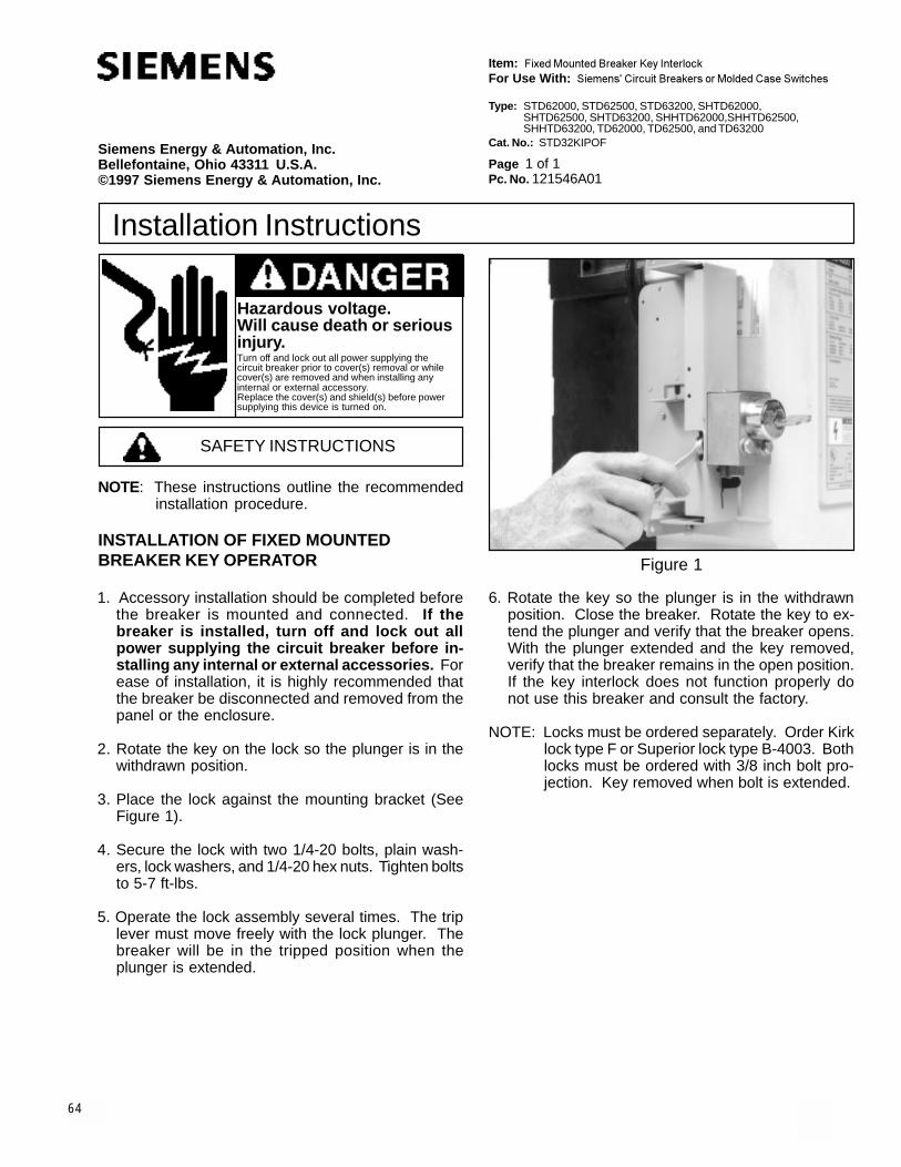
64
Item: ������������� ���� �������� ����For Use With: ���������� ����� ���� ��� ���������������������
Page 1 of 1Pc. No. 121546A01
Siemens Energy & Automation, Inc.Bellefontaine, Ohio 43311 U.S.A.©1997 Siemens Energy & Automation, Inc.
Installation Instructions
SAFETY INSTRUCTIONS
NOTE: These instructions outline the recommendedinstallation procedure.
6. Rotate the key so the plunger is in the withdrawnposition. Close the breaker. Rotate the key to ex-tend the plunger and verify that the breaker opens.With the plunger extended and the key removed,verify that the breaker remains in the open position.If the key interlock does not function properly donot use this breaker and consult the factory.
NOTE: Locks must be ordered separately. Order Kirklock type F or Superior lock type B-4003. Bothlocks must be ordered with 3/8 inch bolt pro-jection. Key removed when bolt is extended.
Figure 1
Type: STD62000, STD62500, STD63200, SHTD62000,SHTD62500, SHTD63200, SHHTD62000,SHHTD62500,SHHTD63200, TD62000, TD62500, and TD63200
Cat. No.: STD32KIPOF
1. Accessory installation should be completed beforethe breaker is mounted and connected. If thebreaker is installed, turn off and lock out allpower supplying the circuit breaker before in-stalling any internal or external accessories. Forease of installation, it is highly recommended thatthe breaker be disconnected and removed from thepanel or the enclosure.
2. Rotate the key on the lock so the plunger is in thewithdrawn position.
3. Place the lock against the mounting bracket (SeeFigure 1).
4. Secure the lock with two 1/4-20 bolts, plain wash-ers, lock washers, and 1/4-20 hex nuts. Tighten boltsto 5-7 ft-lbs.
5. Operate the lock assembly several times. The triplever must move freely with the lock plunger. Thebreaker will be in the tripped position when theplunger is extended.
INSTALLATION OF FIXED MOUNTEDBREAKER KEY OPERATOR
Hazardous voltage.Will cause death or seriousinjury.Turn off and lock out all power supplying thecircuit breaker prior to cover(s) removal or whilecover(s) are removed and when installing anyinternal or external accessory.Replace the cover(s) and shield(s) before powersupplying this device is turned on.

65
SAFETY INSTRUCTIONS
Siemens Energy & Automation, Inc.Bellefontaine, OH 43311 U.S.A.
Hazardous voltage.Will cause death or seriousinjury.Turn off and lock out all power supplyingthe circuit breaker prior to cover(s)removal or while cover(s) are removedand when installing any internal orexternal accessory.Replace the cover(s) and shield(s)before power supplying this device isturned on.
Installation InstructionsMOUNTING OF PADLOCK DEVICE ASSEMBLY1. Accessory installation should be completed before the
breaker is mounted and connected. If the breaker isinstalled turn off and lock out all power supplyingthe circuit breaker when installing any internal orexternal accessory. For ease of installation, it ishighly recommended that the breaker be disconnectedand removed from the panel or the enclosure.
2. Prior to installation, if padlock device will be used tolock circuit breaker in the ON position, remove Tab"A" (See Figure 2, Page 2) by grasping tab with pliersand using an up and down motion to break tab free.Remove sharp edges with file.
3. Installation of this accessory does not require removalof the breaker cover.NOTE: These instructions outline the recommended
installation procedure.
Figure 1
MOUNTING OF PADLOCK DEVICE
DRIVE SCREWS
BREAKER COVER
PADLOCK DEVICE
Item: Padlock Device Assembly
For use with: Siemens' Circuit Breakers or Molded Case Switches
Type: STD62000, STD62500, STD63200, SHTD62000,SHTD62500, SHTD63200, SHHTD62000, SHHTD62500,SHHTD63200, TD62000, TD62500, and TD63200
Cat. No.: STDPLD
Page 1 of 2

66
Siemens Energy & Automation, Inc.Bellefontaine, OH 43311 U.S.A.
Hazardous voltage.Will cause death orserious injury.Turn off and lock out all power supplyingthe circuit breaker prior to cover(s)removal or while cover(s) are removedand when installing any internal orexternal accessory.Replace the covers and shields beforepower supplying this device is turnedon.
Installation Instructions
Pc. No. 121540A01© 1997 Siemens Energy & Automation, Inc.
Page 2 of 2
2. To padlock breaker in ON position:Note: Requires removal of Tab "A" (See Step 2,Page 1).a. Move breaker handle to ON position.b. Rotate moveable part of padlock device overhandle until .375 inch diameter holes are aligned.c. Install padlock hasp through .375 inch diameterholes.
OPERATION OF PADLOCK DEVICE
IMPORTANT: USE PADLOCK WITH 1/4 INCH MINIMUM DIAMETER HASP.
Figure 2
PADLOCK ASSEMBLY
PADLOCK
BREAKER
4. With breaker in the OFF position, assemble padlockdevice to breaker by positioning over handle as shown(See Figure 1, Page 1). Align mounting holes in pad-lock device with holes in breaker escutcheon and in-sert drive screws. Using a hammer, firmly tap drivescrews into holes until padlock device is secured tobreaker.
OPERATION OF PADLOCK DEVICE ASSEMBLY1. To padlock breaker in OFF position:
a. Move breaker handle to OFF position.b. Rotate moveable part of padlock device towardhandle until .375 inch diameter holes are aligned.c. Install padlock hasp through .375 inch diameterholes.
TAB "A"

67
SAFETY INSTRUCTIONS
Siemens Energy & Automation, Inc.Bellefontaine, OH 43311 U.S.A.
Installation Instructions
Hazardous voltage.Will cause death or seriousinjury.Turn off and lock out all power supplyingthe device prior to cover(s) removal orwhile cover(s) are removed and wheninstalling any internal or externalaccessory.Replace the cover(s) and shield(s)before power supplying this device isturned on.
Installation InstructionsMOUNTING OF TERMINAL BLOCK MOUNT1. Accessory installation should be completed before the
breaker is mounted and connected. If the breaker isinstalled turn off and lock out all power supplyingthe circuit breaker when installing any internal orexternal accessory. For ease of installation, it ishighly recommended that the breaker be disconnectedand removed from the panel or the enclosure.
2. Installation of this accessory does not require removalof the breaker cover.
3. Remove the 4 #10 Phillips head screws on the leftand right sides of the breaker cover (do not removescrews in recesses of the cover). Place the terminalblock mount over the screw holes. Re-install thescrews.
4. Secure the assembly by tightening the cover screws.Torque screws to 28 to 32 in-lbs.
NOTE: These instructions outline the recommendedinstallation procedure.
Figure 1
MOUNTING OF TERMINAL BLOCK MOUNTS
BREAKER COVER
COVER SCREW
TERMINAL BLOCK MOUNT
Item: Terminal Block Mount, Terminal Block Assembly
For use with: Siemens' Circuit Breakers or Molded Case Switches
Type: STD62000, STD62500, STD63200, SHTD62000,SHTD62500, SHTD63200, SHHTD62000, SHHTD62500,SHHTD63200, TD62000, TD62500, and TD63200
Cat. No.: STDTBM, STDTBLT, STDTBLB, STDTBRT, STDTBRB
Page 1 of 2

68
Siemens Energy & Automation, Inc.Bellefontaine, OH 43311 U.S.A.
Installation Instructions
Hazardous voltage.Will cause death or seriousinjury.Turn off and lock out all power supplyingthe device prior to cover(s) removal orwhile cover(s) are removed and wheninstalling any internal or externalaccessory.
Replace the cover(s) and shield(s)before power supplying this device isturned on.
Installation Instructions
Pc. No. 121538A01© 1997 Siemens Energy & Automation, Inc.
Page 2 of 2
MOUNTING OF TERMINAL BLOCK ASSEMBLY1. The terminal block mounts should be installed before
installing the terminal block assemblies. If the terminalblock mounts are not installed see the terminal blockmount instructions on page 1.
2. After the terminal block mounts are installed, insertthe terminal block assembly (See Figure 2).
Note: Each terminal block assembly contains four termi-nal blocks and one label.
3. To ensure proper positioning of the terminal block as-semblies see Figure 3.
4. Insert label into the groove of the terminal block (SeeFigure 2).
Figure 3
TERMINAL BLOCK LOCATION
TERMINAL BLOCK INTERLOCK
Figure 4 Figure 2
MOUNTING OF TERMINAL BLOCKS
LABEL
TERMINAL BLOCKINTERLOCK (See Fig. 4)
TERMINAL BLOCK
STDTBRT
STDTBRB
STDTBLT
STDTBLB

External AccessoriesControl Terminal Blocks
Contact blocks are required for secondary control wiring. The appropriate number and location of contact blocks should be selected from the table below based on the features and accessories ordered on each circuit breaker.
LT
LB
RT
RB
Contact Position Catalog Number
LT STDTBLTLB STDTBLBRT STDTBRTRB STDTBRB
Catalog Number
STDTBM
Accessory
Auxiliary SwitchesZone Bell Alarm
Contact Under- Remote Interlock or Display 1A and 1B 4A and 4BBlock Alarm Shunt voltage Neutral Indication and Module 2A and 2B 5A and 5BPosition Switch Trip Release Sensor Panel ACCESS Relay 3A and 3B 6A and 6B
LT X X X XLB X XRT X XRB X X
Figure 4. Secondary Contact Block Locations
Control Terminal Blocks
Mounting Bracket for Terminal BlockFor mounting Control Terminal Blocks to fixed mountedbreakers. One bracket required for mounting locations LT and LB and a separate bracket required for mountinglocations RT and RB.
69

1
SAFETY INSTRUCTIONS
Installation Instructions
Siemens Energy & Automation, Inc.Bellefontaine, Ohio 43311 U.S.A.© 1997 Siemens Energy & Automation, Inc.
Hazardous voltage.Will cause death or seriousinjury.Turn off and lock out all power supplyingthe circuit breaker prior to cover(s)removal or while cover(s) are removedand when installing any internal orexternal accessory.Replace the cover(s) and shield(s)before power supplying this device isturned on.
MOUNTING OF TERMINAL CONNECTOR1. Accessory installation should be completed before the
breaker is mounted and connected. If the breaker isinstalled turn off and lock out all power supplyingthe circuit breaker when installing any internal orexternal accessory. For ease of installation, it ishighly recommended that the breaker be disconnectedand removed from the panel or the enclosure.
2. Mount terminal connector (A) to the breaker terminal(B) with mounting bolts, nuts, and washers provided(See Figure 1).
3. Torque bolts to 240 in-lbs.
4. This terminal connector is not suitable for horizontalmounting.
Figure 1
NOTE: These instructions outline the recommendedinstallation procedure.
Breaker Breaker
WasherWasher
NutNut
Mounting Bolt (3/8-16)
Mounting Bolt (3/8-16)
BB
AA
Item: Terminal Connector
For use with: Siemens' Circuit Breakers or Molded Case Switches
Type: STD62000, STD62500, STD63200, SHTD62000,SHTD62500, SHTD63200, SHHTD62000, SHHTD62500,SHHTD63200, TD62000, TD62500, and TD63200
Cat. No.: STD32TCON
Page 1 of 1Pc. No. 121539A01
70

71
�������������� �
��������������� ������������������������������������������� �
������������� �������������������������������������������������� ����������������� ��������������� ������������������������������������������������������� ����������� ��������� ���������������
������� �������������������������������������������� ������������ ��������
�����������������������
��������������������������������������������������������������
������������������� ������������������������������������� ��
�����������
��������� �� ���� ����� ���������� � ������� �� ���� �������� ������������ �����������������������
������ ������������ ����������������������������������� �������� ������������ ������������������!�����
�������
������"����������� ���������#����$������������#�����#��# ������%����������#��������!������&�������������� !�����$��� �������'�� ��� "���(�)� ������� �������������� ���������!*(&����������+���$��,����-����. ��� ���������������&������� ��
������ ������"����������� ���������#����$������������#�����#��# ������%����������#����� ���!������&�������������� !������(�����$��� �������'�� ��/ "���(�0�����1&�� ��������#%�����#�&����������� �����#����� ����������� ������# ��������� �����������������������$��,�����)� ������� ����������� ��$��������!*(&����������+���$��,����-����. ��� ���������������&������&� ��
����������� ���������
������� ���������������� ����� ���
����� ��!"#$$$%���!"#&$$%���!"'#$$%��(�!"#$$$%�(�!"#&$$%��(�!"'#$$%��((�!"#$$$%��((�!"#&$$%����((�!"'#$$
������������#$��!%��#&��!%��'#��!
���!���
CAUTION2�#����#� �� ���� ���� ���������� #� �� #� �� ���#����$$�������$��$���$��������������� ���� ��� �#�����
3�����������,��������� ���������
�����$���������������� ��������� ����#��������� �����������������#��# ������%���
�!�" ���� ���� #���� � ����� ��� ��#�������������������$��#�� ���
!�����#�$���%"!*(����������#������,�� !*(�#���������+�������#��#��$- 4�$�����$#������,�� 4�$�����$#������,���
!� 5##����������������� ����#��$������������������%����� �������#����#��������&��'��(������������%�����������%����(���������)�*����))�����&���������'��(��)��������+�����+�����*&�����+��������+�%�'������������������ �����������#�������������������%������#����#����������,���������$�����������#�� ���
�� ���$����%����$ ��������" �&��&���$�� �����
���� ����������*��&� �&�� �����*��� '��(�� ���������������
���������� ���������� 6���%��7����� 5�$���8����� '����
������ ���� ������������� ���� ������������� ���� �������

72
Siemens Energy & Automation, Inc.Bellefontaine, OH 43311 U.S.A.
Hazardous voltage.Will cause death or seriousinjury.
Turn off and lock out all powersupplying the device prior to cover(s)removal or while cover(s) are removedand when installing any internal orexternal accessory.
Replace the cover(s) and shield(s)before power supplying this device isturned on.
Installation Instructions
Figure 1
Page 2 of 5
���������
������������������� ��� ����� � ��������������������������������������� ���������������������������������������������������������������������������������������������������������������������������������� ����������������� ������������ �����!"#����$"��������������������������������������������������������������������� �����������������������������������������������������������������������������������������������������%"�#����$"�����������������������������������������������������
����������� ���������
&� '�� ����������������(�&&�����(�&)��������������� � ���������������������� �������*����������"���� ���������� ���*����"�������������������������������'��� ������� ������������������������+��#����,��&)& %$�
Figure 1
REMOVAL OF BREAKER COVER
COVER
BREAKER
TRIP UNIT
(4) #10 SCREWS
(4) 1/4" SCREWS
BREAKER LABEL
WIRE GUIDE
"PUSH - TO - TRIP" BUTTON
�����������)��������-���������������������
)� ���.�������������� .���������.�������/01�2&3#������������ ������������ ��������������/01�&405#������������ ��������� ������������ .���/���������&1�
6� ���.����������������������� ����/����������6"#����61�
0� ���������������������� ������������������� �������/����������6"�#����61�
$� ���.���������������������������������������������/����������0"�#����61�
-� ������������� �����.���������������������������������������6-������������������������������������������������ ������'��� ������������.����������(�&&�����������������������2!������������� ������(�&&���'��� �������������(�&)����������������������2&$������������� �������(�&)���7�������������� ��� �������������������������� ����������������������������������6-���� ��� ����� ������������������ ���������� �����������������������������������������������&3"�#����$�
�������� ��������������"��������"����� .��������� ���������� ����������������������8����������� ������&)9&0���������������&405����� .���� �������-!9 $��������������2&3�'�����'.���� �������)!96)�������

73
Siemens Energy & Automation, Inc.Bellefontaine, OH 43311 U.S.A.
Hazardous voltage.Will cause death or seriousinjury.
Turn off and lock out all powersupplying the device prior to cover(s)removal or while cover(s) are removedand when installing any internal orexternal accessory.
Replace the cover(s) and shield(s)before power supplying this device isturned on.
Installation Instructions
Page 3 of 5
REMOVAL OF TRIP UNIT
SUPPORT BRACKETPINS
RETAININGSCREW
TRIP UNIT
BREAKER
SLIDE UP
REMOVAL OF TRIP UNIT
SUPPORT BRACKETPINS
TRIP UNIT PLUG
RESETMECHANISM
BREAKER
TRIP UNIT
��������������� �������������
����� ����� ��� �� �� ���� � �� �� ������� � ���������������������������������� ������� ����������� ������������������������������������������
������
��� ������� ���������� ���!�����"��� ����� #�$$ �%���� ����� &��������� ������
������������
��� ������� ���������� ���!�����"��� ����� #�$$ �%���� ����� ��!�����'������ ����� �()� ����*(+�!���������� �����)�(),���������� �����)&��������� ������
Figure 3 Figure 4
BREAKER IS EQUIPPED WITHA NEUTRAL SENSINGTRANSFORMER
720219-A00
��������
+� -���$��$����������'��� �!�����'��������������'�������!�.��!���������������$�����������������'�!�������������������������������!�����/�������������������� ��!�������� ���������������������!�����/ ������������������

74
Siemens Energy & Automation, Inc.Bellefontaine, OH 43311 U.S.A.
Hazardous voltage.Will cause death or seriousinjury.
Turn off and lock out all powersupplying the device prior to cover(s)removal or while cover(s) are removedand when installing any internal orexternal accessory.
Replace the cover(s) and shield(s)before power supplying this device isturned on.
Installation Instructions
Page 4 of 5
TERMINAL FACE
1/4-20 HARDWARERECOMMENDED(NOT PROVIDED)
2.00
7.00 6.10
1.50
1.504.00
1.50
BUS4.00
�������������
��������
1/4-20 HARDWARERECOMMENDED(NOT PROVIDED)
�����
�����
�������
�� ������������������
����� ��������������������������������
���
�����������������
����� ��������������������������������
��
�� ����!
��������������������������� ��������������� ��� � �� ����������������������

75
Siemens Energy & Automation, Inc.Bellefontaine, OH 43311 U.S.A.
Hazardous voltage.Will cause death or seriousinjury.
Turn off and lock out all powersupplying the device prior to cover(s)removal or while cover(s) are removedand when installing any internal orexternal accessory.
Replace the cover(s) and shield(s)before power supplying this device isturned on.
Installation Instructions
Pc. No. 121543A01© 1997 Siemens Energy & Automation, Inc.
Page 5 of 5
����������������
�������� �������
��������������� �������� ��������������
�����������������
������
� �
� � �����������
���������������
��������������������
������������
���
���
BONDINGJUMPER
GROUNDINGELECTRODE
NEUTRALDISCONNECT
4 WIRE LOAD
NEUTRAL SENSINGTRANSFORMER(TERMINAL FACE)
NEUTRALDISCONNECT
4 WIRE LOAD
GROUNDINGELECTRODE
BONDINGJUMPER
NEUTRAL SENSINGTRANSFORMER(TERMINAL FACE)
RESIDUAL MODEREVERSE CONNECTION
Figure 8
LT11
LT12
LT11
LT12
RESIDUAL MODESTANDARD CONNECTION
Figure 7
X1 X2
X1 X2
X1
X2
NEUTRAL LOAD
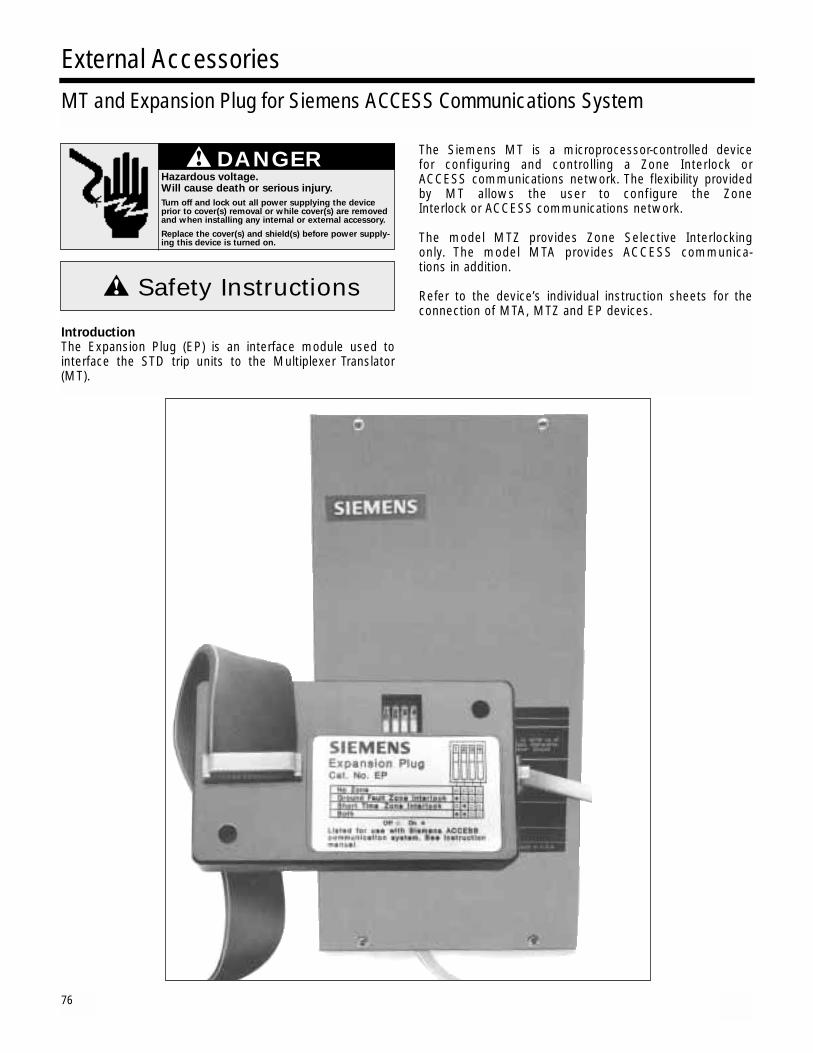
76
Introduction The Expansion Plug (EP) is an interface module used tointerface the STD trip units to the Multiplexer Translator(MT).
The Siemens MT is a microprocessor-controlled device for configuring and controlling a Zone Interlock or ACCESS communications network. The flexibility provided by MT allows the user to configure the Zone Interlock or ACCESS communications network.
The model MTZ provides Zone Selective Interlocking only. The model MTA provides ACCESS communica-tions in addition.
Refer to the device’s individual instruction sheets for theconnection of MTA, MTZ and EP devices.
External AccessoriesMT and Expansion Plug for Siemens ACCESS Communications System
Safety Instructions
DANGERHazardous voltage.Will cause death or serious injury.
Turn off and lock out all power supplying the deviceprior to cover(s) removal or while cover(s) are removedand when installing any internal or external accessory.
Replace the cover(s) and shield(s) before power supply-ing this device is turned on.

77
an
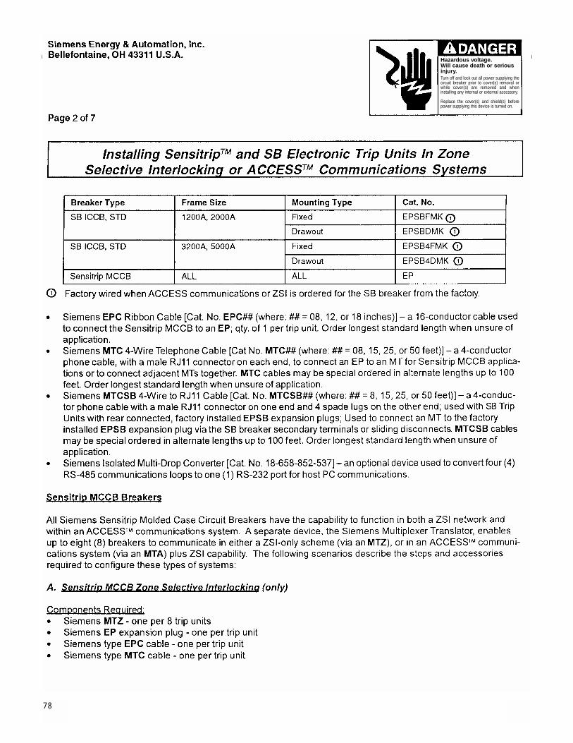
78
Hazardous voltage.Will cause death or seriousinjury.Turn off and lock out all power supplying thecircuit breaker prior to cover(s) removal orwhile cover(s) are removed and wheninstalling any internal or external accessory.
Replace the cover(s) and shield(s) beforepower supplying this device is turned on.
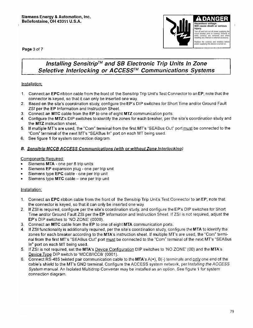
79
Hazardous voltage.Will cause death or seriousinjury.Turn off and lock out all power supplying thecircuit breaker prior to cover(s) removal orwhile cover(s) are removed and wheninstalling any internal or external accessory.
Replace the cover(s) and shield(s) beforepower supplying this device is turned on.
SB and STD Breakers
The following sections describe both types of SB and STD trip units, the standard Type ‘TL’ unit with rotary switches, and the SB Energy-Comm (SB-EC) Trip Unit with keypad and display. Since the SB-EC Trip Unit hasintegral communications capability, the MTA device is not required to connect within an ACCESS system, howeverfor SB-EC Trip Units in a ZSI system, an MTZ or MTA is required.
The type EPSB expansion plug is factory wired to the SB breaker trip unit’s rear connector and also located nearand wired to the SB breaker’s secondary terminal block for fixed mounted breakers or sliding disconnects for drawout breakers. These connections are factory wired when the SB breaker and or STD breaker is ordered withthe standard switch based type ‘TL’ trip unit for ACCESS Communications or for any trip unit with ZSI capability.
Installed ICCB SB or STD breakers without communication capability may be field upgraded for communication capability by Siemens Field Service personnel only.
B. SB and STD Breaker ACCESS Communications (With or without Zone Interlocking)
80

81
Hazardous voltage.Will cause death or seriousinjury.Turn off and lock out all power supplying thecircuit breaker prior to cover(s) removal orwhile cover(s) are removed and wheninstalling any internal or external accessory.
Replace the cover(s) and shield(s) beforepower supplying this device is turned on.
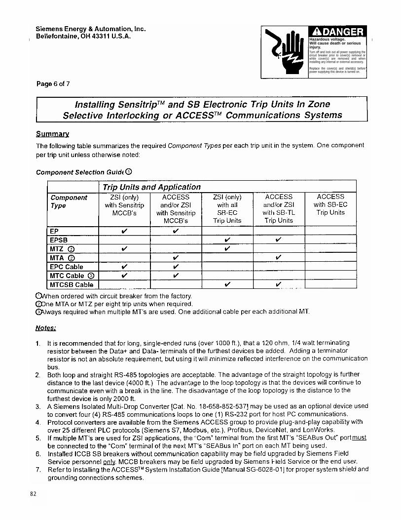
82
Hazardous voltage.Will cause death or seriousinjury.Turn off and lock out all power supplying thecircuit breaker prior to cover(s) removal orwhile cover(s) are removed and wheninstalling any internal or external accessory.
Replace the cover(s) and shield(s) beforepower supplying this device is turned on.

83
Hazardous voltage.Will cause death or seriousinjury.Turn off and lock out all power supplying thecircuit breaker prior to cover(s) removal orwhile cover(s) are removed and wheninstalling any internal or external accessory.
Replace the cover(s) and shield(s) beforepower supplying this device is turned on.

84
General Information(detailed instructions supplied with kit)
GeneralThe TS-31 is a universal test kit to check the tripping functions of Siemens electronic trip units. It functions by injecting current into the current transformer circuits via a test port on the front of the trip unit.
Operations:See the specific TS-31 instructions, furnished with the unit, for detailed operating instructions. One exception tothose instructions pertains to the STD trip unit.
The early TS-31 internal firmware may not recognize STDtrip unit catalog numbers. Consequently, you must enter SB trip unit numbers according to the following substi-tution table.
For this STD Trip Unit Substitute this SB Trip UnitCatalog Number Catalog Number
STD20TLS SB20TLSSTD20TLI SB20TLISTD20TLSI SB20TLSISTD20TLSG SB20TLSGSTD20TLIG SB20TLIGSTD20TLSIG SB20TLSIGSTD25TMLI SB25TMLISTD25TLS SB25TLSSTD25TLI SB25TLISTD25TLSI SB25TLSISTD25TLSG SB25TLSGSTD25TLIG SB25TLIGSTD25TLSIG SB25TLSIGSTD32TMLI SB32TMLISTD32TLS SB32TLSSTD32TLI SB32TLISTD32TLSI SB32TLSISTD32TLSG SB32TLSGSTD32TLIG SB32TLIGSTD32TLSIG SB32TLSIG
Universal Test Kit
External AccessoriesUniversal Test Kit (TS-31)
Safety Instructions
DANGERHazardous voltage.Will cause death or serious injury.
Turn off and lock out all power supplying the deviceprior to cover(s) removal or while cover(s) are removedand when installing any internal or external accessory.
Replace the cover(s) and shield(s) before power supply-ing this device is turned on.

85
Auxiliary Power SupplyThe Auxiliary Power Supply (APS) is used for bench testing the Electronic Trip Unit. The supply may also be used to power the trip unit during the execution of a “go/no-go” type test before bringing the STD breaker on-line (see Monitoring the Trip Unit in the Operating Instruc-tions section). The auxiliary power supply operates from 120V AC source power.
Auxiliary Power Source
Test Procedures1. Remove the clear cover from Trip Unit.
2. To test trip unit, plug the APM into the front of the trip unit.
3. Hold down the Power button on the APM and the desired test buttons on the trip unit. Note that only the Powerbutton must be held down for the duration of the test sequence. If the Power button is released, the test must be restarted.
4. After trip unit test is complete, release the Power button on the APM.
5. Reinstall the clear cover.
External AccessoriesAuxiliary Power Supply
WARNINGTrip Free Condition. Misoperation ormechanism damage can occur ifincorrectly tested.
Release power button on APM beforeclosing breaker mechanism.

86
Outline Dimension DrawingSTD 3200A
HANDLE FORCESOPERATING FORCE WITHOUT WITH
EXTENSION EXTENSIONOFF TO ON 120 LB. 70 LB.ON TO OFF 72 LB. 33 LB.TRIPPED TO RESET 52 LB. 30 LB.
NOTES:1. MOUNTING BOLT TORQUE IS 15 FT - LBS. MAXIMUM
ESCUTCHEON DIMENSIONS
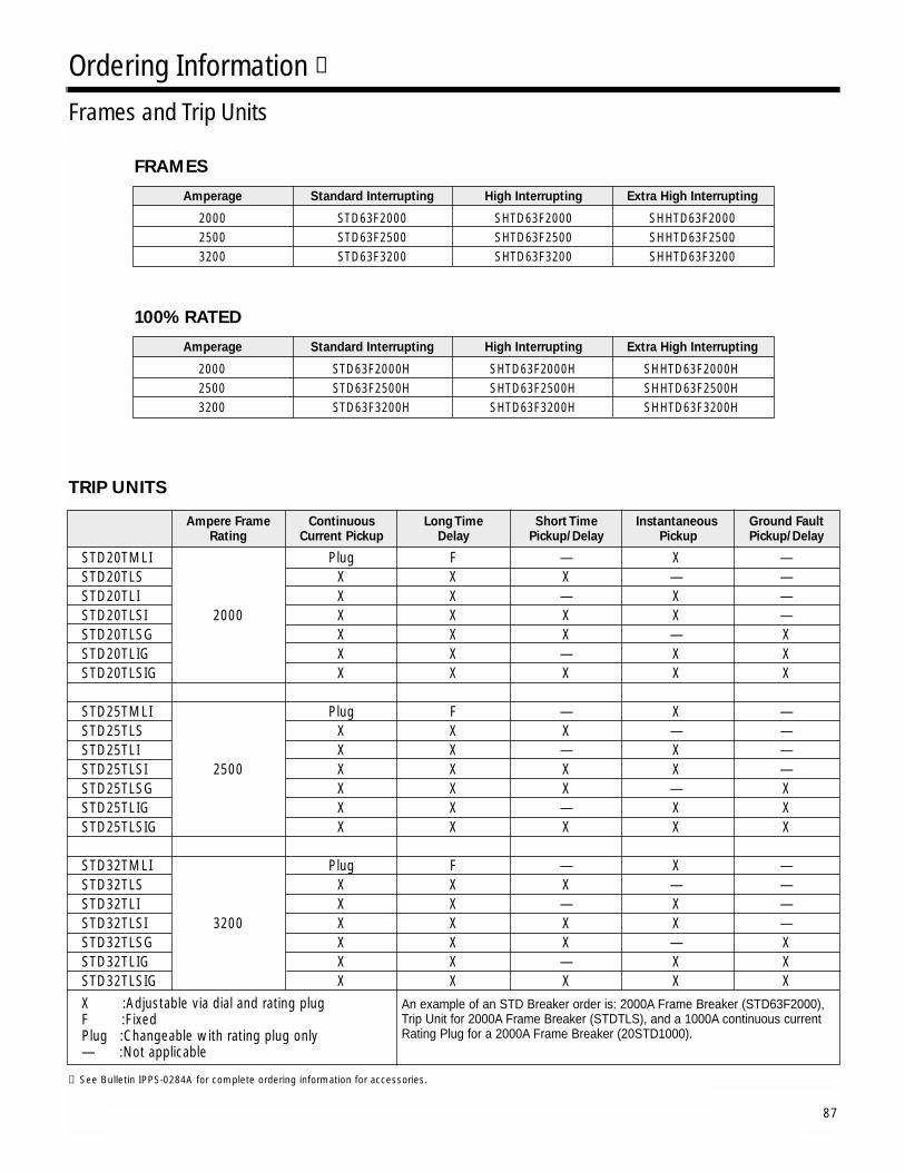
87
Ordering Information ➀
Frames and Trip Units
FRAMES
Amperage Standard Interrupting High Interrupting Extra High Interrupting
2000 STD63F2000 SHTD63F2000 SHHTD63F20002500 STD63F2500 SHTD63F2500 SHHTD63F25003200 STD63F3200 SHTD63F3200 SHHTD63F3200
100% RATED
TRIP UNITS
Amperage Standard Interrupting High Interrupting Extra High Interrupting
2000 STD63F2000H SHTD63F2000H SHHTD63F2000H2500 STD63F2500H SHTD63F2500H SHHTD63F2500H3200 STD63F3200H SHTD63F3200H SHHTD63F3200H
Ampere Frame Continuous Long Time Short Time Instantaneous Ground Fault Rating Current Pickup Delay Pickup/Delay Pickup Pickup/Delay
STD20TMLI Plug F — X —STD20TLS X X X — —STD20TLI X X — X —STD20TLSI 2000 X X X X —STD20TLSG X X X — XSTD20TLIG X X — X XSTD20TLSIG X X X X X
STD25TMLI Plug F — X —STD25TLS X X X — —STD25TLI X X — X —STD25TLSI 2500 X X X X —STD25TLSG X X X — XSTD25TLIG X X — X XSTD25TLSIG X X X X X
STD32TMLI Plug F — X —STD32TLS X X X — —STD32TLI X X — X —STD32TLSI 3200 X X X X —STD32TLSG X X X — XSTD32TLIG X X — X XSTD32TLSIG X X X X XX :Adjustable via dial and rating plugF :FixedPlug :Changeable with rating plug only— :Not applicable
An example of an STD Breaker order is: 2000A Frame Breaker (STD63F2000),Trip Unit for 2000A Frame Breaker (STDTLS), and a 1000A continuous currentRating Plug for a 2000A Frame Breaker (20STD1000).
➀ See Bulletin IPPS-0284A for complete ordering information for accessories.

Siemens Energy & Automation, Inc.3333 Old Milton ParkwayAlpharetta, GA 30005
1-800-964-4114 [email protected]
www.siemens.automation.com
Order # IPIM-0283B 0800B&A
© 2002 Siemens Energy & Automation, Inc. All Rights ReservedSiemens is a registered trademark of Siemens AG. Product names mentioned may be trademarks or registered trademarks of their respective companies. Specifications are subject to change without notice.