información sobre caja de cambios.pdf
TRANSCRIPT

8/11/2019 Información sobre caja de cambios.pdf
http://slidepdf.com/reader/full/informacion-sobre-caja-de-cambiospdf 1/126
Service Manual
Fuller Mid-Range Transmissions
TRSM0110
July 2011
FS-5205A
FS-5205B
FS-5205C
FS-5306A
FS-5406A
FS-5406N
FS-6205A
FS-6205B
FS-6305A
FS-6305B
FS-6306A
FS-6406A
FS-6406N
FSB-5406B
FSO-4305
FSO-6406A
FSO-8406A
Fuller ® Mid-Range Transmissions

8/11/2019 Información sobre caja de cambios.pdf
http://slidepdf.com/reader/full/informacion-sobre-caja-de-cambiospdf 2/126
Warnings and Precautions
Before starting a vehicle always be seated in the driver’s seat, place the transmission in neutral, set the parking brakes anddisengage the clutch.
Before working on a vehicle place the transmission in neutral, set the parking brakes and block the wheels.
Before towing the vehicle place the transmission in neutral, and lift the rear wheels off the ground, remove the axle shafts,
or disconnect the driveline to avoid damage to the transmission during towing.
The description and specifications contained in this service publication are current at the time of printing.
Eaton Corporation reserves the right to discontinue or modify its models and/or procedures and to change specifications at anytime without notice.
Any reference to brand name in this publication is made as an example of the types of tools and materials recommended for useand should not be considered an endorsement. Equivalents may be used.
This symbol is used throughout this manual to call attention to procedures where carelessness or failure to followspecific instructions may result in personal injury and/or component damage.
Departure from the instructions, choice of tools, materials and recommended parts mentioned in this publication may jeopardizethe personal safety of the service technician or vehicle operator.
Warning: Failure to follow indicated procedures creates a high risk of personal injury to the servicing technician.
Caution: Failure to follow indicated procedures may cause component damage or malfunction.
Note: Additional service information not covered in the service procedures.
Tip: Helpful removal and installation procedures to aid in the service of this unit.
Always use genuine Eaton replacement parts.

8/11/2019 Información sobre caja de cambios.pdf
http://slidepdf.com/reader/full/informacion-sobre-caja-de-cambiospdf 3/126
Table of Contents
IntroductionPurpose and Scope of Manual ............... ................ ..... 1How to use this Manual............................................... 1Disassemble Precautions............................................ 1
Inspection Precautions.......... ............... .............. ......... 2Assembly Precautions................................................. 3
Model InformationSerial Tag Information and Model Nomenclature ........ 5Model Number ............................................................ 6Serial Number ............................................................. 6Bill of Material or Customer Number........................... 6
SpecificationsTorque Ratings ............................................................7
Lubrication InformationLubrication .................................................................. 9Maintain Proper Oil Level ............................................ 9Maintenance Interval Chart ....................................... 10Required Lubricant Chart .......................................... 11Transmission Operating Angles ................................ 11
Tool InformationRecommended Tools ............... .............. ................ ... 13Special Tools Manufacturers..................................... 13
Preventive MaintenancePreventive Maintenance ............... ............... .............. 15Checks Before Transmission Removal ...................... 15Checks With Drive Line Dropped...................... ......... 16Checks With Universal Joint Companion Flange
or Yoke Removed .............................................. 16Inspection ................................................................. 17Rear Seal Maintenance.............................................. 17
Power FlowPower Flow ............................................................... 19
In-Vehicle Service ProceduresShift Bar Housing
How to Remove the Gear Shift Lever .............. .......... 23How to Install the Gear Shift Lever ................ ............ 24How to Remove the Shift Bar Housing ...... ................ 25How to Install the Shift Bar Housing ................ ......... 26
Output YokeHow to Remove the Output
Yoke/Companion Flange .....................................27How to Install the Output
Yoke/Companion Flange .....................................28
Clutch HousingHow to Remove the Clutch Housing ..........................29How to Install the Clutch Housing ............... ..............30
Transmission Overhaul Procedures-Bench ServiceShift Bar Housing
Functions of a Shift Bar Housing ... ................ ............31How to Disassemble the Gear Shift Lever ..................32How to Assemble the Gear Shift Lever .............. ........33How to Disassemble the FS-4205
Shift Bar Housing ...............................................34How to Assemble the FS-4205
Shift Bar Housing ...............................................35How to Disassemble the FS-5205
Shift Bar Housing ...............................................37How to Assemble the FS-5205
Shift Bar Housing ...............................................39How to Disassemble the FS-6205/6305
Shift Bar Housing ...............................................41How to Assemble the FS-6205/6305
Shift Bar Housing ...............................................42How to Disassemble the FS-5306/6306/5406/6406
Shift Bar Housing ...............................................44How to Assemble the FS-5306/6306/5406/6406
Shift Bar Housing ...............................................46How to Disassemble the FSO-6406/8406
Shift Bar Housing ...............................................48How to Assemble the FSO-6406/8406
Shift Bar Housing ...............................................50How to Disassemble the Reverse Plunger
on FS-4X05/5X05 ...............................................52How to Assemble the Reverse Plunger
on FS-4X05/5X05 ...............................................53
How to Disassemble the Reverse PlungerFor All Models Except FS-4205/5205 .............. ...54How to Assemble the Reverse Plunger
For All Models Except FS-4205/5205 .............. ...55
8/11/2019 Información sobre caja de cambios.pdf
http://slidepdf.com/reader/full/informacion-sobre-caja-de-cambiospdf 4/126
Table of Contents
Disassemble Main SectionHow to Remove the Input Shaft Assembly ....... ......... 57How to Remove the Mainshaft Assembly .................. 58How to Remove the Countershaft Assembly ...... ....... 59How to Remove the Reverse Idler Gear Assembly
For All Models Except FS-5306/6306 ................. 60How to Remove the FS-5306/6306
Reverse Idler Gear Assembly ............ ............... .. 61
Mainshaft AssemblyHow to Disassemble the FS-4205
Mainshaft Assembly .............. ............... .............. 63How to Assemble the FS-4205
Mainshaft Assembly ............ .............. ............... .. 65How to Disassemble the FS-5205
Mainshaft Assembly .............. ............... .............. 67How to Assemble the FS-5205
Mainshaft Assembly ............ .............. ............... .. 69How to Disassemble the FS-6205
Mainshaft Assembly .............. ............... .............. 71How to Assemble the FS-6205
Mainshaft Assembly ............ .............. ............... .. 73How to Disassemble the FS-6305
Mainshaft Assembly .............. ............... .............. 75How to Assemble the FS-6305
Mainshaft Assembly ............ .............. ............... .. 77How to Disassemble the FS-5306/6306
Mainshaft Assembly .............. ............... .............. 79How to Assemble the FS-5306/6306
Mainshaft Assembly .............. ............... .............. 81How to Disassemble the FS-5406/6406
and FSO-6406 Mainshaft Assembly ........ ........... 84How to Assemble the FS-5406/6406
and FSO-6406 Mainshaft Assembly ........ ........... 86How to Disassemble the FSO-8406
Mainshaft Assembly .............. ............... .............. 89How to Assemble the FSO-8406
Mainshaft Assembly ............ .............. ............... .. 91
Countershaft AssemblyHow to Disassemble the FS-4X05
Countershaft Assembly .............. .............. .......... 95How to Assemble the FS-4X05
Countershaft Assembly .............. .............. .......... 97How to Disassemble the FS-5X05
Countershaft Assembly .............. .............. .......... 99How to Assemble the FS-5X05
Countershaft Assembly .............. .............. ........ 100How to Disassemble the FS-6X05
Countershaft Assembly .............. .............. ........ 101How to Assemble the FS-6X05
Countershaft Assembly .............. .............. ........ 103
How to Disassemble the FS-5306/6306/5406/6406and FSO-6406/8406 Countershaft Assembly ....105
How to Assemble the FS-5306/6306/5406/6406and FSO-6406/8406 CountershaftAssembly ..........................................................107
Disassemble Main SectionHow to Install the Reverse Idler Gear Assembly
For All Models Except FS-5306/6306 ............. ..109How to Install the FS-5306/6306
Reverse Idler Gear Assembly ............................110How to Install the Countershaft Assembly ...............111How to Install the Mainshaft Assembly ....................113How to Install the Input Shaft Assembly ..................115Setting End Play Procedure For All Models
Except FS-5205 ................................................117Setting End Play Procedure For FS-5205 .................119

8/11/2019 Información sobre caja de cambios.pdf
http://slidepdf.com/reader/full/informacion-sobre-caja-de-cambiospdf 5/126
1
Introduction
Purpose and Scope of Manual
This manual is designed to provide detailed information nec-essary to service and repair the Eaton® Fuller® transmis-sions listed on the front.
How to use this Manual
The service procedures have been divided into two sections:In-Vehicle Service Procedures and Transmission OverhaulProcedures—Bench Service. In-Vehicle Service Procedurescontain procedures that can be performed while the transmis-sion is still installed in the vehicle. Transmission OverhaulProcedures contain procedures that are performed after thetransmission has been removed from the vehicle.
The procedure sections are laid out with a general heading atthe top outside edge of each page followed by more specificheadings and the procedures. To find the information youneed in these sections, first go to the section that contains theprocedure you need. Then look at the heading at the top andoutside edge of each page until you find the one that containsthe procedure you need.
Transmission Overhaul Procedures follow the general stepsfor complete disassembly and then assembly of the transmis-sion.
Note: In some instances the transmission appearance may bedifferent from the illustrations, but the procedure is thesame.
Disassemble Precautions
It is assumed in the detailed assembly instructions that thelubricant has been drained from the transmission, the neces-sary linkage and vehicle air lines disconnected and the trans-mission has been removed from vehicle chassis. Removal ofthe gear shift lever housing assembly (or remote controlassembly) is included in the detailed instructions (How toRemove the Gear Shift Lever). This assembly MUST bedetached from the shift bar housing before the transmissioncan be removed.
Follow closely each procedure in the detailed instructions,make use of the text, illustrations, and photographs pro-vided.
AssembliesWhen disassembling the various assemblies, such as themainshaft, countershafts, and shift bar housing, lay all partson a clean bench in the same sequence as removed. This pro-cedure will simplify assembly and reduce the possibility oflosing parts.
BearingsCarefully wash and lubricate all usable bearings as removedand protectively wrap until ready for use. Remove bearingsplanned to be reused with pullers designed for this purpose.
CleanlinessProvide a clean place to work. It is important that no dirt orforeign material enters the unit during repairs. Dirt is an abra-sive and can damage bearings. It is always a good practice toclean the outside of the unit before starting the planned disas-sembly.
Input ShaftThe input shaft can be removed from the transmission with-out removing the countershafts, or mainshaft. Special proce-dures are required and provided in this manual.
Snap RingsRemove snap rings with pliers designed for this purpose.
Snap rings removed in this manner can be reused, if they arenot sprung or loose.
When Using Tools to Move PartsAlways apply force to shafts, housings, etc., with restraint.Movement of some parts is restricted. Never apply force todriven parts after they stop solidly. The use of soft hammers,soft bars, and mauls for all disassembly work is recom-mended.

8/11/2019 Información sobre caja de cambios.pdf
http://slidepdf.com/reader/full/informacion-sobre-caja-de-cambiospdf 6/126
2
Introduction
Inspection Precautions
Before assembling the transmission, check each part carefullyfor abnormal or excessive wear and damage to determinereuse or replacement. When replacement is necessary, useonly genuine Eaton® Fuller® Transmission parts to assurecontinued performance and extended life from your unit.
Since the cost of a new part is generally a small fraction of thetotal cost of downtime and labor, avoid reusing a questionablepart which could lead to additional repairs and expense soonafter assembly. To aid in determining the reuse or replace-ment of any transmission part, consideration should also begiven to the unit's history, mileage, application, etc.
Recommended inspection procedures are provided in the fol-lowing checklist.
Bearings
• Wash all bearings in clean solvent. Check balls, roll-ers, and raceways for pitting, discoloration, andspalled areas. Replace bearings that are pitted, dis-colored, spalled, or damaged during disassembly.
• Lubricate bearings that are not pitted, discolored, orspalled and check for axial and radial clearances.
• Replace bearings with excessive clearances.
• Check bearing fit. Bearing inner races should be tightto shaft; outer races slightly tight to slightly loose in
case bore. If the bearing spins freely in the bore thecase should be replaced.
Bearing Covers
• Check covers for wear from thrust of adjacent bear-ing. Replace covers damaged from thrust of bearingouter race.
• Check cover bores for wear. Replace those worn oroversized.
Clutch Release Parts
• Check clutch release parts. Replace yokes worn atcam surfaces and bearing carrier worn at contactpads.
• Check pedal shafts. Replace those worn at bushingsurfaces.
Gears
• Check gear teeth for frosting and pitting. Frosting ofgear teeth faces presents no threat of transmissionfailure. Often in continued operation of the unit,frosted gears "heal" and do not progress to the pit-ting stage. In most cases, gears with light to moder-ate pitted teeth have considerable gear life remainingand can be reused, but gears in the advanced stageof pitting should be replaced.
• Check for gears with clutching teeth abnormallyworn, tapered, or reduced in length from clashingduring shifting. Replace gears found in any of theseconditions.
• Check axial clearance of gears.
Gear Shift Lever Housing Assembly
• Check spring tension on shift lever. Replace tensionspring if lever moves too freely.
• If housing is disassembled, check gear shift leverbottom end and shift finger assembly for wear.Replace both gears if excessively worn.
Gray Iron Parts
• Check all gray iron parts for cracks and breaks.Replace parts found to be damaged.
Oil Return Threads and Seals
• Check oil return threads on the input shaft. If return
action of threads has been destroyed, replace theinput shaft.
• Check oil seal in rear bearing cover. If sealing actionof lip has been destroyed, replace seal.
O-Rings
• Check all O-rings for cracks or distortion. Replace ifworn.
Reverse Idler Gear Assemblies
• Check for excessive wear from action of roller bear-ings.

8/11/2019 Información sobre caja de cambios.pdf
http://slidepdf.com/reader/full/informacion-sobre-caja-de-cambiospdf 7/126
3
Introduction
Shift Bar Housing Assembly
• Check for wear on shift yokes and blocks at pads andlever slot. Replace excessively worn parts.
• Check yokes for correct alignment. Replace sprung
yokes.• Check lockscrews in yoke and blocks. Tighten and
rewire those found loose.
• If housing has been disassembled, check neutralnotches of shift bars for wear from interlock balls.
Sliding Clutches
• Check all shift yokes and yoke slots in slidingclutches for extreme wear or discoloration fromheat.
• Check engaging teeth of sliding clutches for partial
engagement pattern.Splines
• Check splines on all shafts for abnormal wear. Ifsliding clutch gears, companion flange, or clutchhub has wear marks in the spline sides, replace thespecific shaft effected.
Synchronizer Assembly
• Check synchronizer for burrs, uneven and excessivewear at contact surface, and metal particles.
• Check blocker pins for excessive wear or looseness.
• Check synchronizer contact surfaces on the syn-chronizer cups for wear.
Washers
• Check surfaces of all washers. Washers scored orreduced in thickness should be replaced.
Assembly Precautions
Make sure that case interiors and housings are clean. It isimportant that dirt and other foreign materials are kept out ofthe transmission during assembly. Dirt is an abrasive and candamage polished surfaces of bearings and washers. Use cer-tain precautions, as listed below, during assembly.
Bearings
• Use a flange-end bearing driver for bearing installa-tion. These special drivers apply equal force to bothbearing races, preventing damage to balls/rollersand races while maintaining correct bearing align-ment with bore and shaft. Avoid using a tubular orsleeve-type driver, whenever possible, as force isapplied to only one of the bearing races.
Capscrews
• To prevent oil leakage and loosening, use Eaton/ Fuller sealant #71225 on all capscrews.
Gaskets
• Use new gaskets throughout the transmission as it isbeing rebuilt. Make sure all gaskets are installed. Anomission of any gasket can result in oil leakage ormisalignment of bearing covers.
Initial Lubrication
• Coat all limit washers and shaft splines with Lubri-cant during assembly to prevent scoring and gallingof such parts.
O-Rings
• Lubricate all O-rings with silicon lubricant.
Shims
• Apply a light coat of Eaton/Fuller sealant #71233 toboth sides of shims
Universal Joint Companion Flange or Yoke
• Pull the companion flange or yoke tightly into placewith the output shaft nut. Make sure the speedome-
ter drive gear or a replacement spacer of the samewidth has been installed. Failure to pull the compan-ion flange or yoke tightly into place can result indamage to the mainshaft rear bearing.
IMPORTANT:See the appropriate Illustrated Parts Lists(specified by model series) to ensure that proper parts areused during assembly of the transmission.

8/11/2019 Información sobre caja de cambios.pdf
http://slidepdf.com/reader/full/informacion-sobre-caja-de-cambiospdf 8/126
4
Introduction
8/11/2019 Información sobre caja de cambios.pdf
http://slidepdf.com/reader/full/informacion-sobre-caja-de-cambiospdf 9/126
5
Model Information
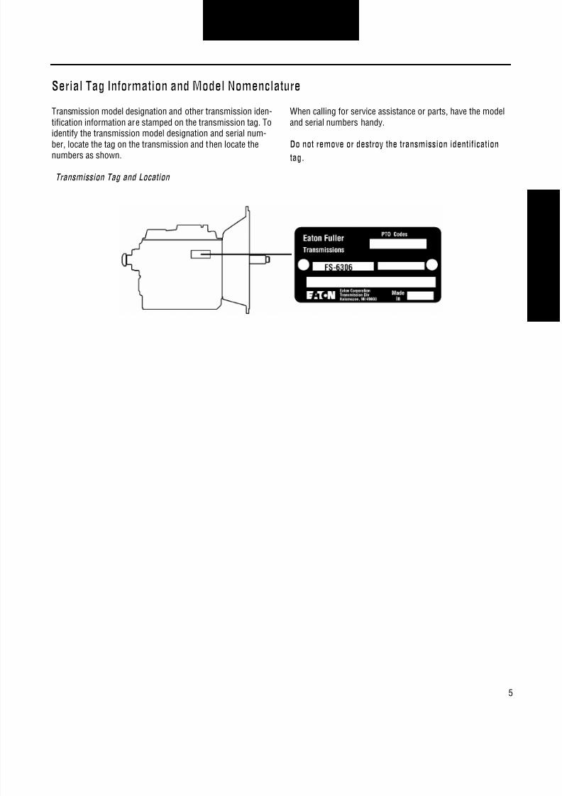
Serial Tag Information and Model Nomenclature
Transmission model designation and other transmission iden-tification information are stamped on the transmission tag. Toidentify the transmission model designation and serial num-ber, locate the tag on the transmission and then locate thenumbers as shown.
When calling for service assistance or parts, have the modeland serial numbers handy.
Do not remove or destroy the transmission identificationtag.
Transmission Tag and Location

8/11/2019 Información sobre caja de cambios.pdf
http://slidepdf.com/reader/full/informacion-sobre-caja-de-cambiospdf 10/126
6
Model Information
Model Number
The model number gives basic information about the trans-mission and is explained below. Use this number when callingfor service assistance or replacement parts.
Serial Number
The serial number is the sequential identification number ofthe transmission. Before calling for service assistance, writethe number down. It may be needed.
Bill of Material or Customer Number
This number is also referred to as the "TA#" and is locatedbelow the model and serial numbers. It is a reference numberused by Eaton® and is helpful if calling for technical support.
8/11/2019 Información sobre caja de cambios.pdf
http://slidepdf.com/reader/full/informacion-sobre-caja-de-cambiospdf 11/126
7
Specifications
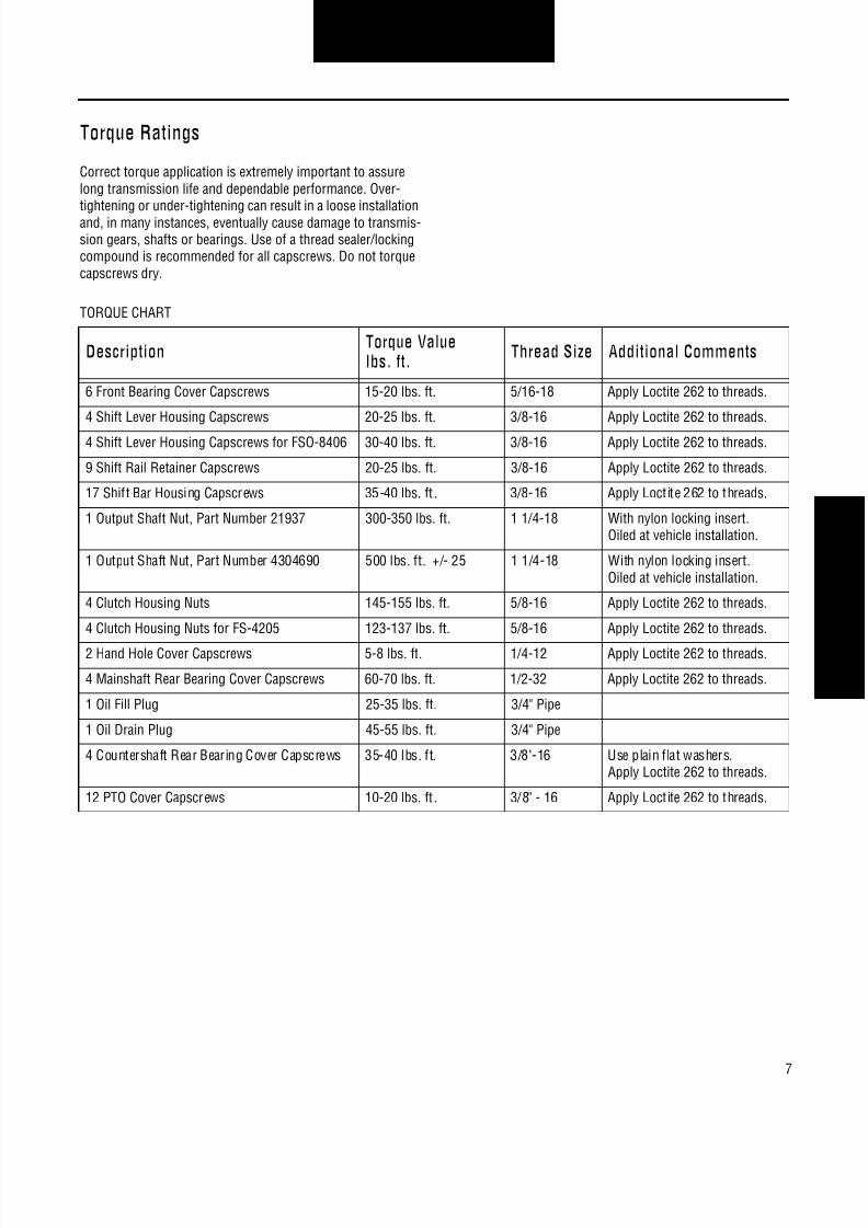
Torque Ratings
Correct torque application is extremely important to assurelong transmission life and dependable performance. Over-tightening or under-tightening can result in a loose installationand, in many instances, eventually cause damage to transmis-sion gears, shafts or bearings. Use of a thread sealer/lockingcompound is recommended for all capscrews. Do not torquecapscrews dry.
TORQUE CHART
Description Torque Valuelbs. ft. Thread Size Additional Comments
6 Front Bearing Cover Capscrews 15-20 lbs. ft. 5/16-18 Apply Loctite 262 to threads.
4 Shift Lever Housing Capscrews 20-25 lbs. ft. 3/8-16 Apply Loctite 262 to threads.
4 Shift Lever Housing Capscrews for FSO-8406 30-40 lbs. ft. 3/8-16 Apply Loctite 262 to threads.
9 Shift Rail Retainer Capscrews 20-25 lbs. ft. 3/8-16 Apply Loctite 262 to threads.
17 Shift Bar Housing Capscrews 35-40 lbs. ft . 3/8-16 Apply Loctite 262 to threads.
1 Output Shaft Nut, Part Number 21937 300-350 lbs. ft. 1 1/4-18 With nylon locking insert.Oiled at vehicle installation.
1 Output Shaft Nut, Part Number 4304690 500 lbs. ft. +/- 25 1 1/4-18 With nylon locking insert.Oiled at vehicle installation.
4 Clutch Housing Nuts 145-155 lbs. ft. 5/8-16 Apply Loctite 262 to threads.
4 Clutch Housing Nuts for FS-4205 123-137 lbs. ft. 5/8-16 Apply Loctite 262 to threads.
2 Hand Hole Cover Capscrews 5-8 lbs. ft. 1/4-12 Apply Loctite 262 to threads.
4 Mainshaft Rear Bearing Cover Capscrews 60-70 lbs. ft. 1/2-32 Apply Loctite 262 to threads.
1 Oil Fill Plug 25-35 lbs. ft. 3/4" Pipe
1 Oil Drain Plug 45-55 lbs. ft. 3/4" Pipe
4 Countershaft Rear Bearing Cover Capscrews 35-40 lbs. ft. 3/8"-16 Use plain flat washers.Apply Loctite 262 to threads.
12 PTO Cover Capscrews 10-20 lbs. ft . 3/8" - 16 Apply Loctite 262 to threads.

8/11/2019 Información sobre caja de cambios.pdf
http://slidepdf.com/reader/full/informacion-sobre-caja-de-cambiospdf 12/126
8
Specifications

8/11/2019 Información sobre caja de cambios.pdf
http://slidepdf.com/reader/full/informacion-sobre-caja-de-cambiospdf 13/126
9
Lubrication Information
Lubrication
Proper lubrication procedures are the key to a good all-aroundmaintenance program.
Eaton® Fuller® Transmissions are designed so that the inter-nal parts operate in an oil circulating bath created by themotion of the gears and shafts.
All parts will be properly lubricated if these procedures areclosely followed:
1. Maintain oil level. Inspect regularly.
2. Follow maintenance interval chart.
3. Use the correct grade and type of oil.
4. Buy from a reputable dealer.
Maintain Proper Oil Level
Make sure oil is level with the filler opening. Being able toreach oil with your finger does not mean oil is at proper level.(One inch of oil level is about one gallon of oil.)
When adding oil, never mix engine oils and gear oils in the
Oil Level
Improper Oil LevelHoleProper Oil LevelHole
8/11/2019 Información sobre caja de cambios.pdf
http://slidepdf.com/reader/full/informacion-sobre-caja-de-cambiospdf 14/126
10
Lubrication Information
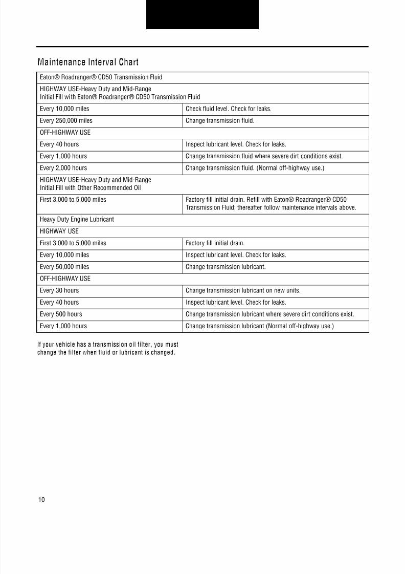
Maintenance Interval Chart
If your vehicle has a transmission oil filter, you mustchange the filter when fluid or lubricant is changed.
Eaton® Roadranger® CD50 Transmission Fluid
HIGHWAY USE-Heavy Duty and Mid-RangeInitial Fill with Eaton® Roadranger® CD50 Transmission Fluid
Every 10,000 miles Check fluid level. Check for leaks.
Every 250,000 miles Change transmission fluid.
OFF-HIGHWAY USE
Every 40 hours Inspect lubricant level. Check for leaks.
Every 1,000 hours Change transmission fluid where severe dirt conditions exist.
Every 2,000 hours Change transmission fluid. (Normal off-highway use.)
HIGHWAY USE-Heavy Duty and Mid-RangeInitial Fill with Other Recommended Oil
First 3,000 to 5,000 miles Factory fill initial drain. Refill with Eaton® Roadranger® CD50Transmission Fluid; thereafter follow maintenance intervals above.
Heavy Duty Engine Lubricant
HIGHWAY USE
First 3,000 to 5,000 miles Factory fill initial drain.
Every 10,000 miles Inspect lubricant level. Check for leaks.
Every 50,000 miles Change transmission lubricant.
OFF-HIGHWAY USE
Every 30 hours Change transmission lubricant on new units.
Every 40 hours Inspect lubricant level. Check for leaks.Every 500 hours Change transmission lubricant where severe dirt conditions exist.
Every 1,000 hours Change transmission lubricant (Normal off-highway use.)

8/11/2019 Información sobre caja de cambios.pdf
http://slidepdf.com/reader/full/informacion-sobre-caja-de-cambiospdf 15/126
11
Lubrication Information
Required Lubricant Chart
The use of lubricants not meeting these requirements willaffect warranty coverage.
For a list of Eaton Approved Synthetic Lubricants, call1-800-826-HELP (4357).
Buy from a reputable dealer
For a complete list of approved and reputable dealers, writeto:
Eaton CorporationWorldwide Marketing ServicesP.O. Box 4013Kalamazoo, MI 49003
Transmission Operating Angles
If the transmission operating angle is more than 12 degrees,improper lubrication will occur. The operating angle is thetransmission mounting angle in the chassis plus the percentof upgrade (expressed in degrees).
Type Grade (SAE) Fahrenheit Ambient Temperature
Eaton® Approved SyntheticTransmission Oil
50 All
Heavy Duty Engine Oil MIL-L-2104D,API-CD, or Cat TO-4
50 Above 10° F (-12° C)
40 Above 10° F (-12° C)
30 Below 10° F (-12° C)
Additives and friction modifiers must not be introduced.Never mix engine oils & gear oils in the same transmission.
LUBE LEVELS
Model Fill Limit
FS-4005 9.5 pints
FS-5005 10.5 pints
FS-42/5205 11.5 pints
FS-62/6305 19 pints
FS-53/6306 18 pintsFS-5406 18 pints
FS/FSO-6406 19.5 pints
FSO-8406 19.5 pints

8/11/2019 Información sobre caja de cambios.pdf
http://slidepdf.com/reader/full/informacion-sobre-caja-de-cambiospdf 16/126
12
Lubrication Information

8/11/2019 Información sobre caja de cambios.pdf
http://slidepdf.com/reader/full/informacion-sobre-caja-de-cambiospdf 17/126
13
Tool Information
Recommended Tools
Some repair procedures pictured in this manual show the useof specialized tools. Their actual use is recommended as theymake transmission repair easier, faster, and prevent costlydamage to critical parts.
But for the most part, ordinary mechanic's tools such assocket wrenches, screwdrivers, etc., and other standard shopitems such as a press, mauls and soft bars are all that isneeded to successfully disassemble and reassemble anyEaton Fuller Transmission.
The specialized tools can be obtained from a tool supplier ormade from tool prints as required by the individual user.Detailed Eaton Fuller Transmission Tool Prints are availableupon request by writing to:
Eaton CorporationTruck Components OperationsTechnical ServiceP.O. Box 4013Kalamazoo, Michigan 49003
Special Tools Manufacturers
Below are the addresses and phone numbers of the compa-nies that make tools specifically for Eaton® Fuller® transmis-sions.
G and W Tool Company1105 E. LouisvilleBroken Arrow, OK 74012-5724800-247-5882
Great Lakes Tool8530 M-89Richland, MI 49083800-877-9618
O.T.C.655 Eisenhower Dr.Owatonna, MN 55060-1171800-533-6127
The specialized tools can be obtained from a tool supplier ormade from tool prints as required by the individual user.Detailed Eaton Fuller Transmission Tool Prints are available
upon request by writing to:
Eaton CorporationTruck Components OperationsTechnical ServiceP.O. Box 4013Kalamazoo, Michigan 49003
SPECIAL TOOLS
REFERENCE
NUMBER
TOOL HOW OBTAINED
T1 Tension Spring Driver Made from Fuller Transmission Print T-11938
T2 Snap Ring Pliers Tool Supplier
T3 Impact Puller (1/2-13 Threaded End) Tool Supplier
T4 Countershaft Support Tools and Bearing Driver Made from Fuller Transmission Print T-22913-C
T5 Bearing Guide Made from Fuller Transmission Print T-18042-110
T6 Oil Seal Driver, Rear Bearing Cover Made from Fuller Transmission Print T-18088-61
T7 Input Shaft Nut Installer Made from Fuller Transmission Print T-22553-A
T8 Torque Wrench, 1000 lbs. ft. Capacity Tool Supplier
T9 Oil Seal Driver, Front Bearing Cover (push type clutch) Made from Fuller Transmission Print T-18088-67
T10 Oil Seal Driver, Front Bearing Cover (pull type clutch) Made from Fuller Transmission Print T-18088-64

8/11/2019 Información sobre caja de cambios.pdf
http://slidepdf.com/reader/full/informacion-sobre-caja-de-cambiospdf 18/126
14
Tool Information
8/11/2019 Información sobre caja de cambios.pdf
http://slidepdf.com/reader/full/informacion-sobre-caja-de-cambiospdf 19/126
15
Preventive Maintenance
Preventive Maintenance
Everyday there are countless vehicles operating over the high-ways with transmissions in such a neglected mechanical con-dition, they can be referred to as failures looking for a place tobreak down. They lack a proper and organized preventivemaintenance program.
Preventive maintenance is a general term which applies to allprocedures necessary to have maximum life and satisfactoryservice at the lowest possible cost, short of removing andrepairing the unit.
Checks Before Transmission Removal
A number of conditions contrary to good preventive mainte-nance can generally be pointed to when inspecting a failedtransmission. Taking a few minutes every so many hours ormiles to do a few simple checks could help avoid eventualbreakdown or reduce the repair cost. If the transmission isnot cared for, it will breakdown.
Transmission appearance may differ, however the procedureis the same.
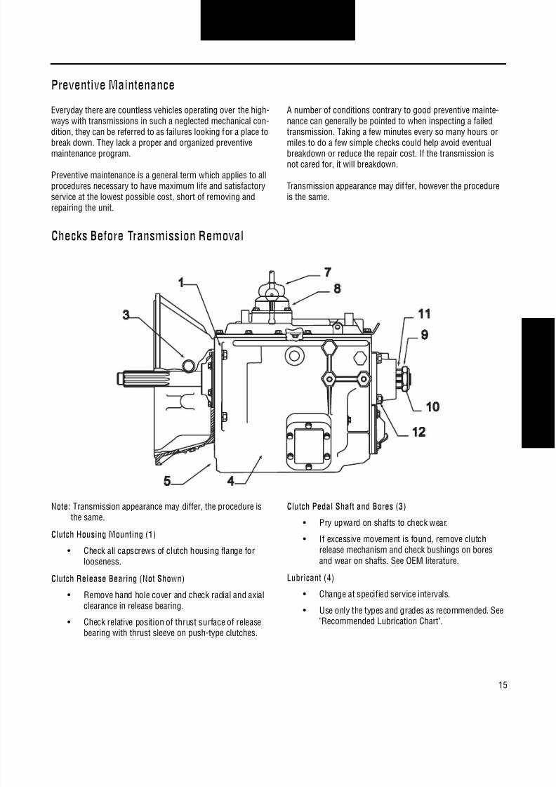
Note: Transmission appearance may differ, the procedure isthe same.
Clutch Housing Mounting (1)
• Check all capscrews of clutch housing flange forlooseness.
Clutch Release Bearing (Not Shown)
• Remove hand hole cover and check radial and axialclearance in release bearing.
• Check relative position of thrust surface of releasebearing with thrust sleeve on push-type clutches.
Clutch Pedal Shaft and Bores (3)
• Pry upward on shafts to check wear.
• If excessive movement is found, remove clutch
release mechanism and check bushings on boresand wear on shafts. See OEM literature.
Lubricant (4)
• Change at specified service intervals.
• Use only the types and grades as recommended. See"Recommended Lubrication Chart".

8/11/2019 Información sobre caja de cambios.pdf
http://slidepdf.com/reader/full/informacion-sobre-caja-de-cambiospdf 20/126
16
Preventive Maintenance
Filler and Drain Plugs (5)
• Remove filler plugs and check level of lubricant atspecified intervals. Tighten fill and drain plugssecurely.
Capscrews and Gaskets (6)• Check all capscrews, especially those on PTO covers
and rear bearing covers for looseness which wouldcause oil leakage.
• Check PTO opening and rear bearing covers for oilleakage due to faulty gasket.
Gear Shift Lever (7)
• Check for looseness and free play in housing. If leveris loose in housing, check Gear Shift Lever HousingAssembly.
Gear Shift Lever Housing Assembly (8)• Remove the gear shift lever housing assembly from
the transmission.
• Check the tension spring and washer for set andwear.
• Check gear shift lever bottom end for wear in theslots and check for wear of finger assembly andhousing.
Checks With Drive Line DroppedUniversal Joint Companion Flange or Yoke Nut (9)
• Check for tightness. Tighten to recommendedtorque.
Output Shaft (Yoke Nut Tightened)
• Pry upward against output shaft to check radialclearance in mainshaft rear bearing.
Checks With Universal Joint CompanionFlange or Yoke RemovedNote: If necessary, use solvent and shop rag to clean sealing
surface of companion flange or yoke. Do not use crocuscloth, emery paper, or other abrasive materials that will
mar surface finish.Splines on Output Shaft (11)
• Check for wear from movement and chucking actionof the universal joint companion flange or yoke.
Mainshaft Rear Bearing Cover (12)
• Check oil seal for wear.

8/11/2019 Información sobre caja de cambios.pdf
http://slidepdf.com/reader/full/informacion-sobre-caja-de-cambiospdf 21/126

8/11/2019 Información sobre caja de cambios.pdf
http://slidepdf.com/reader/full/informacion-sobre-caja-de-cambiospdf 22/126
18
Preventive Maintenance

8/11/2019 Información sobre caja de cambios.pdf
http://slidepdf.com/reader/full/informacion-sobre-caja-de-cambiospdf 23/126
19
Power Flow
Power Flow
The transmission must efficiently transfer the engine's power,in terms of torque, to the vehicle's rear wheels. Knowledge ofwhat takes place in the transmission during torque transfer isessential when trouble-shooting and when making repairsbecome necessary.
1. Power (torque) from the engine is transferred to thetransmission input shaft.
2. Torque is transferred to countershaft drive gear.
3. Torque is delivered along countershaft to all counter-shaft gears.
4. Torque is transferred to "engaged" mainshaft gear.The cross section view illustrates 1st speed gearposition.
5. The engaged mainshaft gear external clutching teethtransfer torque to the mainshaft through the syn-chronizer assembly or sliding clutch.
6. The mainshaft transfers torque directly to driveshaftthrough the output yoke.
FS-5205 First Gear

8/11/2019 Información sobre caja de cambios.pdf
http://slidepdf.com/reader/full/informacion-sobre-caja-de-cambiospdf 24/126
20
Power Flow
FS-5205 Second Gear
FS-5205 Third Gear

8/11/2019 Información sobre caja de cambios.pdf
http://slidepdf.com/reader/full/informacion-sobre-caja-de-cambiospdf 25/126
21
Power Flow
FS-5205 Fourth Gear
FS-5205 Fifth Gear or Direct

8/11/2019 Información sobre caja de cambios.pdf
http://slidepdf.com/reader/full/informacion-sobre-caja-de-cambiospdf 26/126
22
Power Flow

8/11/2019 Información sobre caja de cambios.pdf
http://slidepdf.com/reader/full/informacion-sobre-caja-de-cambiospdf 27/126
23
In-Vehicle Service Procedures
How to Remove the Gear Shift Lever
Special Instructions
Remote control housings are removed the same way as gear shift levers.
Procedure -
1. From the gear shift lever base, remove the four (4) retain-ing capscrews.
2. To break the gasket seal, lightly jar the gear shift housing.
3. Remove the gear shift lever housing.
4. Remove the gasket and clean all mounting surfaces ofgasket material.

8/11/2019 Información sobre caja de cambios.pdf
http://slidepdf.com/reader/full/informacion-sobre-caja-de-cambiospdf 28/126
8/11/2019 Información sobre caja de cambios.pdf
http://slidepdf.com/reader/full/informacion-sobre-caja-de-cambiospdf 29/126
25
In-Vehicle Service Procedures
How to Remove the Shift Bar Housing
Special Instructions
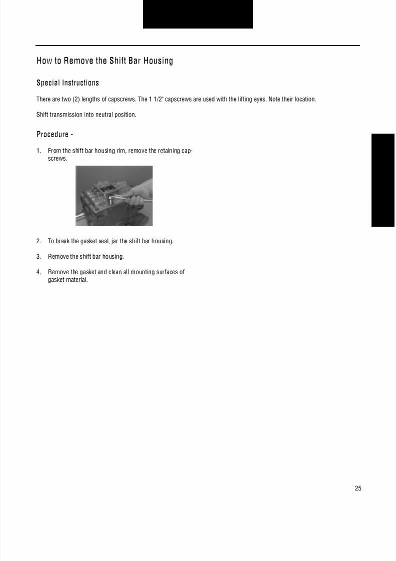
There are two (2) lengths of capscrews. The 1 1/2" capscrews are used with the lifting eyes. Note their location.
Shift transmission into neutral position.
Procedure -
1. From the shift bar housing rim, remove the retaining cap-screws.
2. To break the gasket seal, jar the shift bar housing.
3. Remove the shift bar housing.
4. Remove the gasket and clean all mounting surfaces ofgasket material.

8/11/2019 Información sobre caja de cambios.pdf
http://slidepdf.com/reader/full/informacion-sobre-caja-de-cambiospdf 30/126
26
In-Vehicle Service Procedures
How to Install the Shift Bar Housing
Special Instructions
There are two (2) lengths of capscrews. The 1 1/2" capscrews are used with the lifting eyes.
Apply Eaton/Fuller gasket sealant #71233 or equivalent to shift bar housing gasket before assembly.
Procedure -
1. Place the shift bars in the neutral position.
2. Place the synchronizers in the neutral position.
3. Position a new shift bar housing gasket on the shift barhousing mounting surface.
4. As you install the shift bar housing, make sure the yokesfit onto the corresponding synchronizers.
5. Apply Eaton/Fuller sealant #71225 or equivalent to theretaining capscrews, if not precoated.
6. Install the center rear retaining capscrew first and thecenter front retaining capscrew second, tighten to 35-40lbs. ft. of torque.
7. Install the remaining capscrews, tighten to 35-40 lbs. ft.of torque.
Final Check
Make sure the capscrews are properly torqued.

8/11/2019 Información sobre caja de cambios.pdf
http://slidepdf.com/reader/full/informacion-sobre-caja-de-cambiospdf 31/126
27
In-Vehicle Service Procedures
How to Remove the Output Yoke/Companion Flange
Special Instructions
You must remove the shift bar housing in order to lock the transmission.
Special Tools
A large breaker bar or air impact wrench
Procedure -
1. Engage two (2) mainshaft synchronizers into two (2)mainshaft gears to lock the transmission.
2. Use a breaker bar to remove the nut from the outputshaft.
3. Pull the output yoke or flange straight to the rear and offthe output shaft.

8/11/2019 Información sobre caja de cambios.pdf
http://slidepdf.com/reader/full/informacion-sobre-caja-de-cambiospdf 32/126
28
In-Vehicle Service Procedures
How to Install the Output Yoke/Companion Flange
Special Instructions
You must remove the shift bar housing in order to lock the transmission.
Special Tools
Torque wrench with 500 lbs. ft. capacity
Procedure -
1. Engage two (2) mainshaft synchronizers into two (2)mainshaft gears to lock the transmission.
2. Install the speedometer drive gear rotor or replacementspacer on the output shaft inside the rear bearing cover.
3. Slide the companion flange or yoke onto the outputshaft.
4. Install the output shaft nut, tighten to 300-350 lbs. ft. oftorque.
Final Check
Make sure the output shaft nut is properly torqued.
Unlock the transmission.

8/11/2019 Información sobre caja de cambios.pdf
http://slidepdf.com/reader/full/informacion-sobre-caja-de-cambiospdf 33/126
29
In-Vehicle Service Procedures
How to Remove the Clutch Housing
Special Instructions
Removal of the clutch housing is done in the horizontal position.
Procedure -
1. Remove the four clutch housing retaining bolts from thecase and clutch housing.
2. Jar clutch housing with a rubber mallet and pull theclutch housing from transmission case.

8/11/2019 Información sobre caja de cambios.pdf
http://slidepdf.com/reader/full/informacion-sobre-caja-de-cambiospdf 34/126
30
In-Vehicle Service Procedures
How to Install the Clutch Housing
Procedure -
1. Position clutch housing on front of transmission.
2. Install four retaining bolts and torque to the recom-mended torque.

8/11/2019 Información sobre caja de cambios.pdf
http://slidepdf.com/reader/full/informacion-sobre-caja-de-cambiospdf 35/126
31
Transmission OverhaulProcedures-Bench Service
Functions of a Shift Bar Housing
Shift bar housings are a very important part of the transmis-sion. No matter what kind of shift bar housing your transmis-sion has, they all provide the same functions:
• Engage the transmission gearing,
• Prevents the driver from shifting into 2 gears at thesame time,
• Prevents shifting into reverse without force,
• Actuates the back up lights,
• Actuates the neutral switches.

8/11/2019 Información sobre caja de cambios.pdf
http://slidepdf.com/reader/full/informacion-sobre-caja-de-cambiospdf 36/126
32
Transmission OverhaulProcedures-Bench Service
How to Disassemble the Gear Shift Lever
Special Instructions
For safety reasons when disassembling the gear shift lever, release the spring one coil at a time.
WARNING:Wear safety glasses when removing spring.
Special Tools
Vise with brass jaws or wood blocks
Procedure -
1. Remove the shift lever boot.
2. Slide the boot up the shift lever shaft and remove.
3. With housing bottom facing up, secure the assembly in avise.
4. Use large screwdriver to twist between the spring andhousing, forcing the spring from under the housing lugs.
5. From inside the housing tower, remove the tensionspring, washer, and gear shift lever.
6. From the housing tower remove spade pin bores, andinspect the spade pins, discard if damaged.
7. If housing tower spade pin bores are worn, discard thehousing tower and replace with a new housing tower.
8/11/2019 Información sobre caja de cambios.pdf
http://slidepdf.com/reader/full/informacion-sobre-caja-de-cambiospdf 37/126
33
Transmission OverhaulProcedures-Bench Service
How to Assemble the Gear Shift Lever
Special Instructions
Inspect tension spring, washer, and pivot pin bores for wear. (Replace, if oblong.)
Apply oil to the shift lever pivot ball and housing socket prior to assembly.
Seat the tension spring one coil at a time.
Special Tools
See Recommended Tools on page 13 .
Vise with brass jaws or wood blocks
Item T1: Tension spring driver
Procedure -
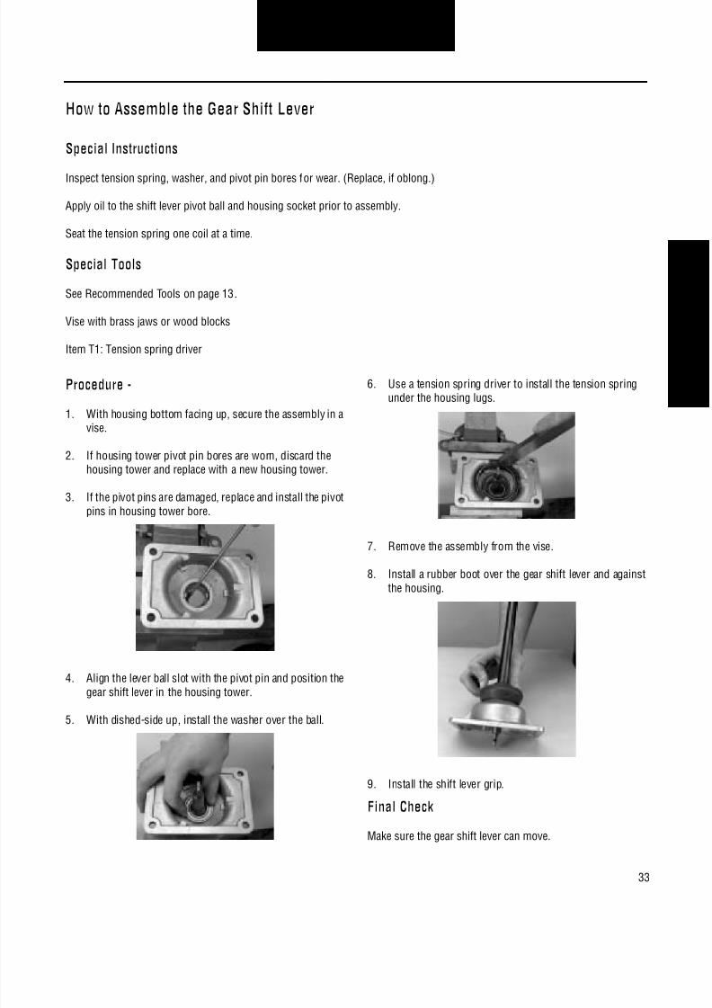
1. With housing bottom facing up, secure the assembly in avise.
2. If housing tower pivot pin bores are worn, discard thehousing tower and replace with a new housing tower.
3. If the pivot pins are damaged, replace and install the pivotpins in housing tower bore.
4. Align the lever ball slot with the pivot pin and position thegear shift lever in the housing tower.
5. With dished-side up, install the washer over the ball.
6. Use a tension spring driver to install the tension springunder the housing lugs.
7. Remove the assembly from the vise.
8. Install a rubber boot over the gear shift lever and againstthe housing.
9. Install the shift lever grip.
Final Check
Make sure the gear shift lever can move.
8/11/2019 Información sobre caja de cambios.pdf
http://slidepdf.com/reader/full/informacion-sobre-caja-de-cambiospdf 38/126
34
Transmission OverhaulProcedures-Bench Service
How to Disassemble the FS-4205 Shift Bar Housing
Special Instructions
The shift bar housing must be removed from the transmission.
During disassembly, lay all parts on a clean bench in order of removal to facilitate assembly.
Shift bars not being removed must be kept in the neutral position or the interlocking parts lock the bars.
Start with 1st-reverse yoke assembly.
When removing the interlock balls, detent balls, and springs, remove the interlock and detent balls before removing the springs.
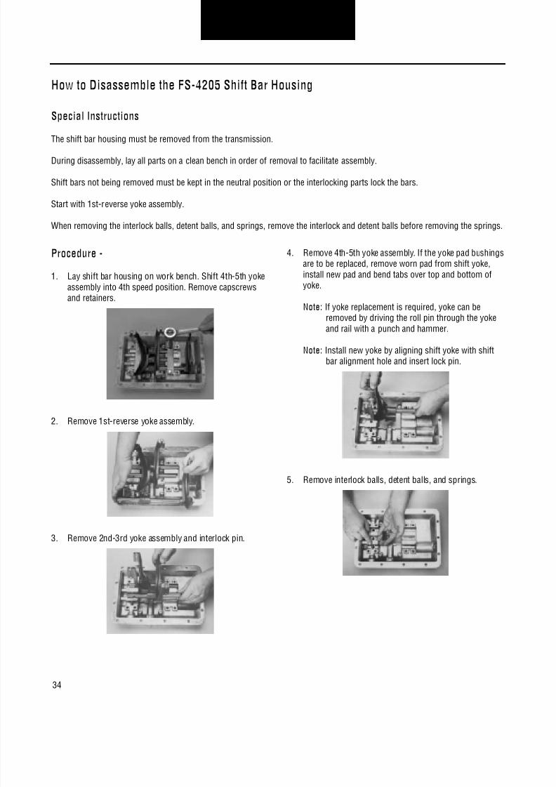
Procedure -
1. Lay shift bar housing on work bench. Shift 4th-5th yokeassembly into 4th speed position. Remove capscrewsand retainers.
2. Remove 1st-reverse yoke assembly.
3. Remove 2nd-3rd yoke assembly and interlock pin.
4. Remove 4th-5th yoke assembly. If the yoke pad bushingsare to be replaced, remove worn pad from shift yoke,
install new pad and bend tabs over top and bottom ofyoke.
Note: If yoke replacement is required, yoke can beremoved by driving the roll pin through the yokeand rail with a punch and hammer.
Note: Install new yoke by aligning shift yoke with shiftbar alignment hole and insert lock pin.
5. Remove interlock balls, detent balls, and springs.

8/11/2019 Información sobre caja de cambios.pdf
http://slidepdf.com/reader/full/informacion-sobre-caja-de-cambiospdf 39/126
35
Transmission OverhaulProcedures-Bench Service
How to Assemble the FS-4205 Shift Bar Housing
Special Instructions
Interlock balls, detent balls, and springs can be used interchangeably.
Lubricate yoke pads and inserts with oil before assembly.
Lubricate yoke bar grooves with grease before assembly.
Keep yoke bars in neutral while assembling.
The shift yoke retainer holes are not tapped on new shift bar housings. The capscrews that are used are "thread forming" and canbe reused if the shift bar housing is replaced.
It may be necessary to support the yoke bars in position while installing the retainers.
Procedure -
1. Install interlock balls, detent balls and springs in the fol-lowing sequence;A. Position (3) balls in the reverse light switch bore.B. Install 1st-reverse detent spring and ball.C. Position (2) balls in adjacent cross bore.D. Install 2nd-3rd detent spring and ball.E. Position (2) balls in adjacent cross boreF. Install 4th-5th detent spring and ball.
Note: Balls and springs can be used interchangeably.
2. Position 1st-reverse yoke in housing assembly as shown.
3. Install interlock pin in 2nd-3rd yoke assembly and posi-tion as shown.
4. Position 4th-5th yoke assembly in housing as shown.

8/11/2019 Información sobre caja de cambios.pdf
http://slidepdf.com/reader/full/informacion-sobre-caja-de-cambiospdf 40/126
36
Transmission OverhaulProcedures-Bench Service
5. Position shift yokes as shown. Install front and rearretainer over shift rails and install front two capscrews.Tighten all rail support capscrews to 20-25 lbs. ft. (27-34N•m).
Note: It may be necessary to support rails in proper posi-tion while installing rail supports.

8/11/2019 Información sobre caja de cambios.pdf
http://slidepdf.com/reader/full/informacion-sobre-caja-de-cambiospdf 41/126
37
Transmission OverhaulProcedures-Bench Service
How to Disassemble the FS-5205 Shift Bar Housing
Special Instructions
The shift bar housing must be removed from the transmission.
During disassembly, lay all parts on a clean bench in order of removal to facilitate assembly.
Shift bars not being removed must be kept in the neutral position or the interlocking parts lock the bars.
Start with 4th-5th yoke assembly.
When removing the interlock balls, detent balls, and springs, remove the interlock and detent balls before removing the springs.
Special Tools
Magnet
Procedure -
1. With the housing rear to the right, lay the assembly on aflat surface.
2. In order to remove the front retaining capscrews, shift4th-5th yoke assembly into 4th gear position (rearward).
3. Remove capscrews and retainers.
4. Remove 4th-5th yoke assembly.
5. Remove 2nd-3rd yoke assembly and interlock pin.
6. Remove 1st-reverse bar assembly.

8/11/2019 Información sobre caja de cambios.pdf
http://slidepdf.com/reader/full/informacion-sobre-caja-de-cambiospdf 42/126

8/11/2019 Información sobre caja de cambios.pdf
http://slidepdf.com/reader/full/informacion-sobre-caja-de-cambiospdf 43/126
39
Transmission OverhaulProcedures-Bench Service
How to Assemble the FS-5205 Shift Bar Housing
Special Instructions
Interlock balls, detent balls, and springs can be used interchangeably.
Lubricate yoke pads and inserts with oil before assembly.
Lubricate yoke bar grooves with grease before assembly.
Keep yoke bars in neutral while assembling.
The shift yoke retainer holes are not tapped on new shift bar housings. The capscrews that are used are "thread forming" and canbe reused if the shift bar housing is replaced.
It may be necessary to support the yoke bars in position while installing the retainers.
Procedure -
1. Install interlock balls, detent balls and springs in the fol-lowing sequence;A. Position (3) balls in the reverse light switch bore.B. Install 1st-reverse detent spring and ball.C. Position (2) balls in adjacent cross bore.D. Install 2nd-3rd detent spring and ball.E. Position (2) balls in adjacent cross boreF. Install 4th-5th detent spring and ball.
Note: Balls and springs can be used interchangeably.
2. Over the actuator pivot pin, seat the 1st reverse actuator.
3. Position 1st-reverse yoke in housing assembly as shown.
4. Install the 1st-reverse lock pin in the yoke assembly.
5. Position 1st-reverse bar assembly in the housing.
6. Install interlock pin in 2nd-3rd yoke assembly and posi-tion as shown.
7. Position 4th-5th yoke assembly in housing as shown.

8/11/2019 Información sobre caja de cambios.pdf
http://slidepdf.com/reader/full/informacion-sobre-caja-de-cambiospdf 44/126
40
Transmission OverhaulProcedures-Bench Service
8. Position retainers, front retainer in rear set of holes.
9. Install the capscrews in rear retainer. Tighten all rail sup-port capscrews to 20-25 lbs. ft. (27-34 N•m).
Note: It may be necessary to support rails in proper posi-tion while installing rail supports.
10. Carefully shift the 4th-5th yoke into 4th gear position(rearward).
11. Install the capscrews in front retainer. Tighten all rail sup-port capscrews to 20-25 lbs. ft. (27-34 N•m).
8/11/2019 Información sobre caja de cambios.pdf
http://slidepdf.com/reader/full/informacion-sobre-caja-de-cambiospdf 45/126
41
Transmission OverhaulProcedures-Bench Service
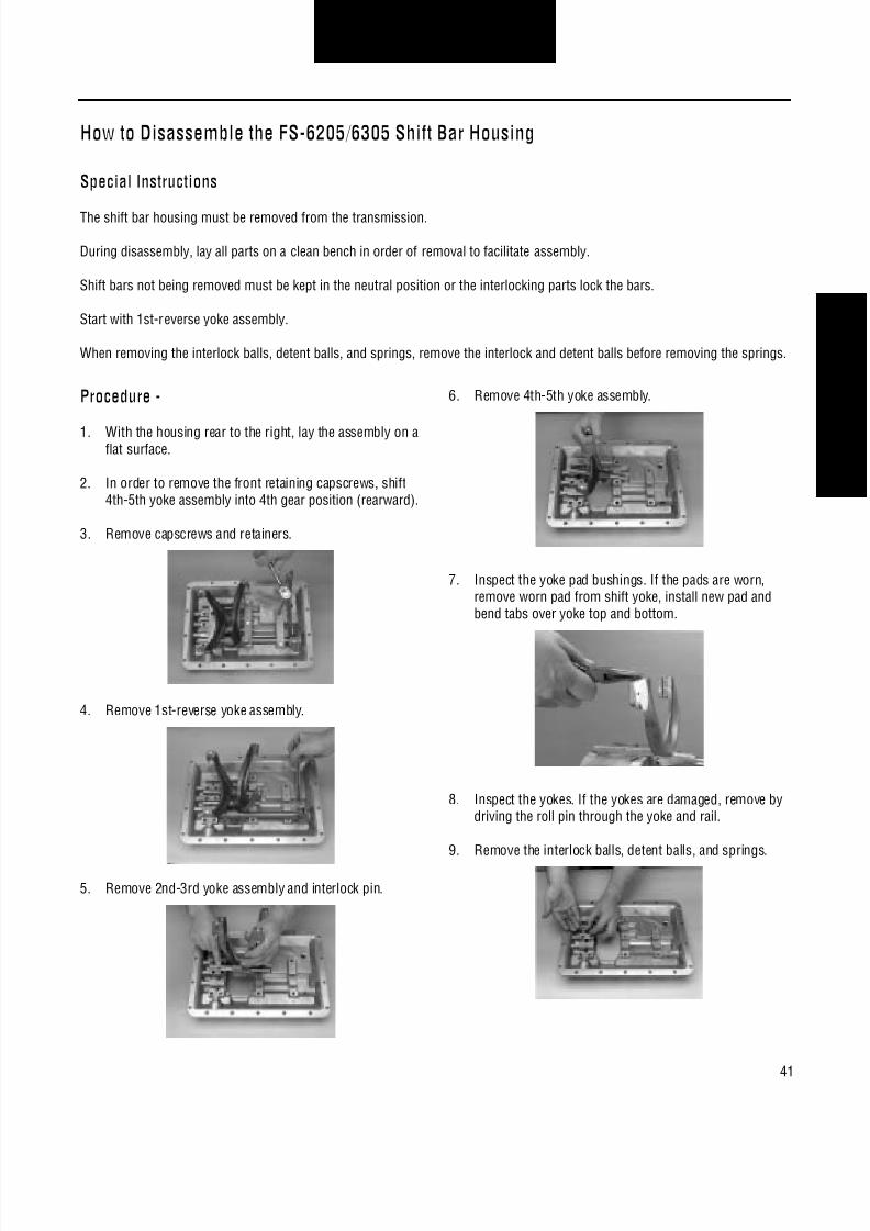
How to Disassemble the FS-6205/6305 Shift Bar Housing
Special Instructions
The shift bar housing must be removed from the transmission.
During disassembly, lay all parts on a clean bench in order of removal to facilitate assembly.
Shift bars not being removed must be kept in the neutral position or the interlocking parts lock the bars.
Start with 1st-reverse yoke assembly.
When removing the interlock balls, detent balls, and springs, remove the interlock and detent balls before removing the springs.
Procedure -
1. With the housing rear to the right, lay the assembly on aflat surface.
2. In order to remove the front retaining capscrews, shift4th-5th yoke assembly into 4th gear position (rearward).
3. Remove capscrews and retainers.
4. Remove 1st-reverse yoke assembly.
5. Remove 2nd-3rd yoke assembly and interlock pin.
6. Remove 4th-5th yoke assembly.
7. Inspect the yoke pad bushings. If the pads are worn,remove worn pad from shift yoke, install new pad andbend tabs over yoke top and bottom.
8. Inspect the yokes. If the yokes are damaged, remove bydriving the roll pin through the yoke and rail.
9. Remove the interlock balls, detent balls, and springs.

8/11/2019 Información sobre caja de cambios.pdf
http://slidepdf.com/reader/full/informacion-sobre-caja-de-cambiospdf 46/126
42
Transmission OverhaulProcedures-Bench Service
How to Assemble the FS-6205/6305 Shift Bar Housing
Special Instructions
Interlock balls, detent balls, and springs can be used interchangeably.
Lubricate yoke pads and inserts with oil before assembly.
Lubricate yoke bar grooves with grease before assembly.
Keep yoke bars in neutral while assembling.
The shift yoke retainer holes are not tapped on new shift bar housings. The capscrews that are used are "thread forming" and canbe reused if the shift bar housing is replaced.
It may be necessary to support the yoke bars in position while installing the retainers.
Procedure -
1. Install interlock balls, detent balls and springs in the fol-lowing sequence;A. Position (3) balls in the reverse light switch bore.B. Install 1st-reverse detent spring and ball.C. Position (2) balls in adjacent cross bore.D. Install 2nd-3rd detent spring and ball.E. Position (2) balls in adjacent cross boreF. Install 4th-5th detent spring and ball.
Note: Balls and springs can be used interchangeably.
2. Position 1st-reverse yoke in housing assembly as shown.
3. Install the interlock pin in 2nd-3rd yoke assembly.
4. Position 2nd-3rd yoke in housing assembly.
5. Position 4th-5th yoke in housing assembly.
6. Position retainers, front retainer in rear set of holes.

8/11/2019 Información sobre caja de cambios.pdf
http://slidepdf.com/reader/full/informacion-sobre-caja-de-cambiospdf 47/126
43
Transmission OverhaulProcedures-Bench Service
7. Install the capscrews in the middle and rear retainer.Tighten all rail support capscrews to 20-25 lbs. ft. (27-34N•m).
Note: It may be necessary to support rails in proper posi-
tion while installing rail supports.
8. Carefully shift the 4th-5th yoke into 4th gear position(rearward).
9. Install the capscrews in front retainer. Tighten all rail sup-port capscrews to 20-25 lbs. ft. (27-34 N•m).
Final Check
Make sure interlocking system is working - can't shift into 2gears at the same time.

8/11/2019 Información sobre caja de cambios.pdf
http://slidepdf.com/reader/full/informacion-sobre-caja-de-cambiospdf 48/126
44
Transmission OverhaulProcedures-Bench Service
How to Disassemble the FS-5306/6306/5406/6406 Shift Bar Housing
Special Instructions
The shift bar housing must be removed from the transmission.
During disassembly, lay all parts on a clean bench in order of removal to facilitate assembly.
Shift bars not being removed must be kept in the neutral position or the interlocking parts lock the bars.
Start with reverse yoke assembly.
When removing the interlock balls, detent balls, and springs, remove the interlock and detent balls before removing the springs.
Procedure -
1. With the housing rear to the right, lay the assembly on aflat surface.
2. In order to remove the front retaining capscrews, shift5th-6th yoke assembly into 5th gear position (rearward).
3. Remove capscrews and retainers.
4. Remove reverse yoke assembly.
5. Remove 1st-2nd yoke assembly and interlock pin.
6. Remove 3rd-4th yoke assembly and interlock pin.
7. Remove 5th-6th yoke assembly.
8. Inspect the yoke pad bushings. If the pads are worn,remove worn pad from shift yoke, install new pad andbend tabs over yoke top and bottom.

8/11/2019 Información sobre caja de cambios.pdf
http://slidepdf.com/reader/full/informacion-sobre-caja-de-cambiospdf 49/126
45
Transmission OverhaulProcedures-Bench Service
9. Inspect the yokes. If the yokes are damaged, remove bydriving the roll pin through the yoke and rail.
10. Remove the interlock balls, detent balls, and springs.

8/11/2019 Información sobre caja de cambios.pdf
http://slidepdf.com/reader/full/informacion-sobre-caja-de-cambiospdf 50/126
46
Transmission OverhaulProcedures-Bench Service
How to Assemble the FS-5306/6306/5406/6406 Shift Bar Housing
Special Instructions
Interlock balls, detent balls, and springs can be used interchangeably.
Lubricate yoke pads and inserts with oil before assembly.
Lubricate yoke bar grooves with grease before assembly.
Keep yoke bars in neutral while assembling.
The shift yoke retainer holes are not tapped on new shift bar housings. The capscrews that are used are "thread forming" and canbe reused if the shift bar housing is replaced.
It may be necessary to support the yoke bars in position while installing the retainers.
Procedure -
1. Install interlock balls, detent balls and springs in the fol-lowing sequence;A. Position (3) balls in the reverse light switch bore.B. Install reverse detent spring and ball.C. Position (2) balls in adjacent cross bore.D. Repeat steps B and C for 1st-2nd position, 3rd-4thposition, and 5th-6th position.
Note: Balls and springs can be used interchangeably.
2. Position reverse yoke in housing assembly as shown.
3. Install the interlock pin in 1st-2nd yoke assembly.
4. Position 1st-2nd yoke in housing assembly.
5. Install the interlock pin in 3rd-4th yoke assembly.
6. Position 3rd-4th yoke in housing assembly.
7. Position 5th-6th shift block in housing assembly.

8/11/2019 Información sobre caja de cambios.pdf
http://slidepdf.com/reader/full/informacion-sobre-caja-de-cambiospdf 51/126
47
Transmission OverhaulProcedures-Bench Service
8. Position retainers, front retainer in rear set of holes.
9. Install the capscrews in the middle and rear retainers.Tighten all rail support capscrews to 20-25 lbs. ft. (27-34N•m).
Note: It may be necessary to support rails in proper posi-tion while installing rail supports.
10. Carefully shift the 5th-6th yoke into 5th gear position(rearward).
11. Install the capscrews in front retainer. Tighten all rail sup-port capscrews to 20-25 lbs. ft. (27-34 N•m).
Final Check
Make sure interlocking system is working - can't shift into 2gears at the same time.

8/11/2019 Información sobre caja de cambios.pdf
http://slidepdf.com/reader/full/informacion-sobre-caja-de-cambiospdf 52/126
48
Transmission OverhaulProcedures-Bench Service
How to Disassemble the FSO-6406/8406 Shift Bar Housing
Special Instructions
The shift bar housing must be removed from the transmission.
During disassembly, lay all parts on a clean bench in order of removal to facilitate assembly.
Shift bars not being removed must be kept in the neutral position or the interlocking parts lock the bars.
Start with 5th-6th yoke assembly.
When removing the interlock balls, detent balls, and springs, remove the interlock and detent balls before removing the springs.
Procedure -
1. With the housing rear to the right, lay the assembly on aflat surface.
2. Remove capscrews and retainers.
3. Remove 5th-6th yoke assembly.
4. Remove 5th-6th shift block.
5. Remove 3rd-4th yoke assembly and interlock pin.
6. Remove 1st-2nd yoke assembly and interlock pin.
7. Remove reverse yoke assembly.
8. Inspect the yoke pad bushings. If the pads are worn,remove worn pad from shift yoke, install new pad andbend tabs over yoke top and bottom.

8/11/2019 Información sobre caja de cambios.pdf
http://slidepdf.com/reader/full/informacion-sobre-caja-de-cambiospdf 53/126
49
Transmission OverhaulProcedures-Bench Service
9. Inspect the yokes. If the yokes are damaged, remove bydriving the roll pin through the yoke and rail.
10. Remove the interlock balls, detent balls, and springs.

8/11/2019 Información sobre caja de cambios.pdf
http://slidepdf.com/reader/full/informacion-sobre-caja-de-cambiospdf 54/126
50
Transmission OverhaulProcedures-Bench Service
How to Assemble the FSO-6406/8406 Shift Bar Housing
Special Instructions
Interlock balls, detent balls, and springs can be used interchangeably.
Lubricate yoke pads and inserts with oil before assembly.
Lubricate yoke bar grooves with grease before assembly.
Keep yoke bars in neutral while assembling.
The shift yoke retainer holes are not tapped on new shift bar housings. The capscrews that are used are "thread forming" and canbe reused if the shift bar housing is replaced.
It may be necessary to support the yoke bars in position while installing the retainers.
Procedure -
1. Install interlock balls, detent balls and springs in the fol-lowing sequence;A. Position (3) balls in the reverse light switch bore.B. Install reverse detent spring and ball.C. Position (2) balls in adjacent cross bore.D. Repeat steps B and C for 1st-2nd position, 3rd-4thposition, and 5th-6th position.
Note: Balls and springs can be used interchangeably.
2. Position reverse yoke in housing assembly as shown.
3. Install the interlock pin in 1st-2nd yoke assembly.
4. Position 1st-2nd yoke in housing assembly.
5. Install the interlock pin in 3rd-4th yoke assembly.
6. Position 3rd-4th yoke in housing assembly.
7. Position 5th-6th shift block in housing assembly.

8/11/2019 Información sobre caja de cambios.pdf
http://slidepdf.com/reader/full/informacion-sobre-caja-de-cambiospdf 55/126
51
Transmission OverhaulProcedures-Bench Service
8. Install the middle retainer capscrews.
Note: It may be necessary to support rails in proper posi-tion while installing retainer.
9. Position 5th-6th yoke in housing assembly.
Note: The 5th-6th yoke is aligned by the dowel pin andthe capscrew hole shown in the picture.
10. Position the last retainer and start the capscrews in theremaining capscrew holes.
11. Start with the capscrew shown in the picture and tightenall rail support capscrews to 20-25 lbs. ft. (27-34 N•m).
Final Check
Make sure interlocking system is working - can't shift into 2gears at the same time.

8/11/2019 Información sobre caja de cambios.pdf
http://slidepdf.com/reader/full/informacion-sobre-caja-de-cambiospdf 56/126
52
Transmission OverhaulProcedures-Bench Service
How to Disassemble the Reverse Plunger on FS-4X05/5X05
Special Instructions
Retainer is under spring pressure.
Procedure -
1. Remove the reverse plunger retaining plug and gasket.
2. Remove the reverse plunger spring.
3. Remove the reverse plunger stop.
4. Remove the reverse plunger.
5. Inspect reverse plunger. Replace damaged parts.

8/11/2019 Información sobre caja de cambios.pdf
http://slidepdf.com/reader/full/informacion-sobre-caja-de-cambiospdf 57/126
53
Transmission OverhaulProcedures-Bench Service
How to Assemble the Reverse Plunger on FS-4X05/5X05
Special Instructions
With the reverse plunger bore up, place the shift bar housing on its side.
Procedure -
1. Install the reverse plunger.
2. Install the reverse plunger spring.
3. Install the reverse plunger stop.
4. Install the reverse plunger gasket and plug.
5. Tighten the plug to 8-12 lbs. ft. (10.8-16.2 N•m) oftorque.
Final Check
Make sure snap ring is securely in shift block groove.

8/11/2019 Información sobre caja de cambios.pdf
http://slidepdf.com/reader/full/informacion-sobre-caja-de-cambiospdf 58/126
54
Transmission OverhaulProcedures-Bench Service
How to Disassemble the Reverse Plunger For All Models Except FS-4205/5205
Special Instructions
Snap ring and retainer are under spring pressure.
WARNING:Wear safety glasses when removing snap rings.
Procedure -
1. Depress reverse plunger springs and retainer.
2. Remove snap ring and spring retainer.
3. Remove the reverse plunger springs.
4. Remove washer and plunger.
5. Inspect reverse plunger parts. Replace worn or damagedparts.

8/11/2019 Información sobre caja de cambios.pdf
http://slidepdf.com/reader/full/informacion-sobre-caja-de-cambiospdf 59/126
55
Transmission OverhaulProcedures-Bench Service
How to Assemble the Reverse Plunger For All Models Except FS-4205/5205
Special Instructions
Place the reverse yoke bar in a vise.
WARNING:Wear safety glasses when installing snap rings.
Special Tools
Vise with brass jaws or wood blocks
Snap ring pliers
Procedure -
1. Install plunger and washer.
2. Install reverse plunger springs.
3. Depress the reverse plunger retainer and springs.
4. Install the snap ring in the shift block groove.
Final Check
Make sure snap ring is securely in shift block groove.

8/11/2019 Información sobre caja de cambios.pdf
http://slidepdf.com/reader/full/informacion-sobre-caja-de-cambiospdf 60/126
56
Transmission OverhaulProcedures-Bench Service

8/11/2019 Información sobre caja de cambios.pdf
http://slidepdf.com/reader/full/informacion-sobre-caja-de-cambiospdf 61/126

8/11/2019 Información sobre caja de cambios.pdf
http://slidepdf.com/reader/full/informacion-sobre-caja-de-cambiospdf 62/126
58
Transmission OverhaulProcedures-Bench Service
How to Remove the Mainshaft Assembly
Special Instructions
WARNING:Wear safety glasses when removing snap rings.
Special Tools
Sling and hoist
Procedure -
1. Remove the speedometer sleeve and driven gear.
2. Turn out four retaining nuts and lockwashers.
3. Using screwdrivers in notches, remove rear bearingcover. If necessary remove oil seal from cover.
4. Remove shims and speedometer drive gear or rotor.
Note: Shims may come off with rear bearing cover.
5. For the FS-5205 model, tap on the mainshaft front tomove the mainshaft rearward about 1/4". Use pry bars toremove the rear bearing cup and locating snap ring.
6. Wrap a sling around the 3rd-4th synchronizer assembly.Use a hoist to remove the mainshaft assembly from thecase.

8/11/2019 Información sobre caja de cambios.pdf
http://slidepdf.com/reader/full/informacion-sobre-caja-de-cambiospdf 63/126
59
Transmission OverhaulProcedures-Bench Service
How to Remove the Countershaft Assembly
Procedure -
1. Turn out capscrews, remove countershaft rear bearingcover and shims.
2. Remove the countershaft rear bearing cup.
Note: Countershaft may slide to the rear and out of bear-ing bore.
3. Move countershaft assembly to the rear and lift it fromthe case.
4. If countershaft front bearing race is to be replaced, drivebore plug through front of transmission and drive the
race to the rear toward the inside of the case.

8/11/2019 Información sobre caja de cambios.pdf
http://slidepdf.com/reader/full/informacion-sobre-caja-de-cambiospdf 64/126
60
Transmission OverhaulProcedures-Bench Service
How to Remove the Reverse Idler Gear Assembly For All Models Except FS-5306/6306
Special Tools
Rolling wedge bar
Procedure -
1. Remove the reverse idler lock and retaining capscrew.
2. Using a rolling wedge bar, remove reverse idler shaft.
3. Remove reverse idler, bearings, spacer and thrust wash-ers.

8/11/2019 Información sobre caja de cambios.pdf
http://slidepdf.com/reader/full/informacion-sobre-caja-de-cambiospdf 65/126
61
Transmission OverhaulProcedures-Bench Service
How to Remove the FS-5306/6306 Reverse Idler Gear Assembly
Special Tools
Sliding hammer
Procedure -
1. Use the slide hammer and remove reverse idler shaft.
2. Remove the locating ball.
3. Remove reverse idler assembly and thrust washers.
4. From the reverse idler assembly, remove the bearingsand spacer.

8/11/2019 Información sobre caja de cambios.pdf
http://slidepdf.com/reader/full/informacion-sobre-caja-de-cambiospdf 66/126
62
Transmission OverhaulProcedures-Bench Service

8/11/2019 Información sobre caja de cambios.pdf
http://slidepdf.com/reader/full/informacion-sobre-caja-de-cambiospdf 67/126
63
Transmission OverhaulProcedures-Bench Service
How to Disassemble the FS-4205 Mainshaft Assembly
Special Instructions
During disassembly, lay all parts on a clean bench in order of removal to facilitate reassembly.
WARNING:Wear safety glasses when removing snap rings.
Special Tools
Vise with brass jaws or wood blocks
Snap ring pliers
Gear puller
Procedure - See Mainshaft FRONT Facing Up illustration
1. With mainshaft front facing up, install the mainshaftassembly vertically in a vise.
2. Remove shift hub thrust bearing and bearing race.
3. Remove 4th-5th speed synchronizer and cups.
4. Remove 4th-5th clutch hub.
5. Remove 4th gear and 4th gear bearing.
6. Remove 3rd gear retaining snap ring.
7. Remove 3rd gear thrust washer and locating ball.
8. Remove 3rd gear and 3rd gear bearing.
9. Remove 2nd-3rd speed synchronizer and cups.
10. Remove snap ring and 2nd-3rd shift hub.
11. Remove 2nd gear and 2nd gear bearing.
12. Remove split ring retainer ring.
13. Separate split washers and remove half rings and locat-ing ball.
14. Remove 1st gear and 1st gear bearing.
15. Remove 1st-reverse clutch hub.
Procedure - See Mainshaft REAR Facing Up illustration
16. With mainshaft rear facing up, install the mainshaftassembly vertically in a vise.
17. Using a puller, remove reverse gear, washer, and rearbearing.
18. Remove reverse gear bearing.

8/11/2019 Información sobre caja de cambios.pdf
http://slidepdf.com/reader/full/informacion-sobre-caja-de-cambiospdf 68/126
64
Transmission OverhaulProcedures-Bench Service
Mainshaft FRONT Facing Up Mainshaft REAR Facing Up
1. Bearing Race2. Thrust Bearing3. 4th-5th Speed
Synchronizer and Cups
4. 4th-5th Clutch Hub5. 4th Gear6. Gear Bearing7. Snap Ring8. Thrust Washer and
Locating Ball
9. 3rd Gear10. 2nd-3rd Speed
Synchronizer and Cups11. 2nd-3rd Clutch Hub
12. 2nd Gear13. Split Ring Retainer Ring14. Split Washers and
Locating Ball15. 1st Gear16. 1st-Reverse Clutch Hub17. Mainshaft
1. Rear Bearing2. Washer3. Reverse Gear4. Gear Bearing5. Mainshaft

8/11/2019 Información sobre caja de cambios.pdf
http://slidepdf.com/reader/full/informacion-sobre-caja-de-cambiospdf 69/126
65
Transmission OverhaulProcedures-Bench Service
How to Assemble the FS-4205 Mainshaft Assembly
Special Instructions
Lubricate the gear bearing bores, gear hub faces, split washers, synchronizer friction surfaces, synchronizer cups and the main-shaft with transmission lube as the mainshaft is assembled.
WARNING:Wear safety glasses when installing snap rings.
Special Tools
Vise with brass jaws or wood blocks
Sleeve type bearing driver
Snap ring pliers
Procedure - See Mainshaft REAR Facing Up illustration
1. With mainshaft rear facing up, install the mainshaftassembly vertically in a vise.
2. Install reverse gear bearing.
3. With reverse gear clutching teeth down, install reversegear.
4. Install reverse gear washer. Washer can be installed
either way.5. Use a sleeve type bearing driver and install the rear main-
shaft bearing.
Procedure - See Mainshaft FRONT Facing Up illustration
6. With mainshaft front facing up, install the mainshaftassembly vertically in a vise.
7. Install the 1st-reverse clutch hub.
8. Install 1st gear bearing.9. With 1st gear clutching teeth down, install 1st gear.
10. Install locating ball and split washer in mainshaft groove,position split washer ends together at locating ball.
11. Install retainer ring over split washer.
12. Install 2nd gear bearing.
13. With 2nd gear clutching teeth up, install 2nd gear.
14. With 2nd-3rd clutch hub stepped face up, install 2nd-3rdclutch hub.
15. Install snap ring in mainshaft groove.
16. Install 2nd-3rd speed synchronizer and cups.
17. Install 3rd gear bearing.
18. With 3rd gear clutching teeth down, install 3rd gear.
19. Install locating ball and washer. Washer can be installedeither way.
20. Install snap ring in mainshaft groove.
21. Install 4th gear bearing.
22. With 4th gear clutching teeth up, install 4th gear.
23. With 4th-5th clutch hub machined surface up, install 4th-5th clutch hub.
24. Install 4th-5th speed synchronizer and cups.
25. Install the shift hub thrust bearing and bearing race.
Final Check
Make sure the mainshaft gears rotate freely.

8/11/2019 Información sobre caja de cambios.pdf
http://slidepdf.com/reader/full/informacion-sobre-caja-de-cambiospdf 70/126
66
Transmission OverhaulProcedures-Bench Service
Mainshaft REAR Facing Up Mainshaft FRONT Facing Up
1. Rear Bearing2. Washer3. Reverse Gear4. Gear Bearing5. Mainshaft
1. Bearing Race2. Thrust Bearing3. 4th-5th Speed
Synchronizer and Cups
4. 4th-5th Clutch Hub5. 4th Gear6. Gear Bearing7. Snap Ring8. Thrust Washer and
Locating Ball
9. 3rd Gear10. 2nd-3rd Speed
Synchronizer and Cups11. 2nd-3rd Clutch Hub
12. 2nd Gear13. Split Ring Retainer Ring14. Split Washers and
Locating Ball15. 1st Gear16. 1st-Reverse Clutch Hub17. Mainshaft

8/11/2019 Información sobre caja de cambios.pdf
http://slidepdf.com/reader/full/informacion-sobre-caja-de-cambiospdf 71/126
67
Transmission OverhaulProcedures-Bench Service
How to Disassemble the FS-5205 Mainshaft Assembly
Special Instructions
During disassembly, lay all parts on a clean bench in order of removal to facilitate reassembly.
Use caution when removing 1st gear, the needle bearings are loose under 1st gear.
WARNING:Wear safety glasses when removing snap rings.
Special Tools
Vise with brass jaws or wood blocks
Snap ring pliers
Bearing puller
Procedure - See Mainshaft FRONT Facing Up illustration
1. With mainshaft front facing up, install the mainshaftassembly vertically in a vise.
2. Remove 4th~5th speed synchronizer and cups.
3. Remove shift hub thrust bearing and bearing race.
4. Remove 4th-5th clutch hub.
5. Remove 4th gear and 4th gear bearing.
6. Remove 3rd gear retaining snap ring.
7. Remove 3rd gear thrust washer and locating ball.
8. Remove 3rd gear and 3rd gear bearing.
9. Remove 2nd-3rd speed synchronizer and cups.
Procedure - See Mainshaft REAR Facing Up illustration
10. With mainshaft rear facing up, install the mainshaftassembly vertically in a vise.
11. Using a puller, remove mainshaft rear bearing.
12. Remove 1st gear split washer retaining ring.
13. Separate split washers and remove half rings.
14. Remove 1st gear and 1st gear bearing.
15. Remove 1st-reverse sliding clutch.
16. Remove 1st-reverse clutch hub snap ring.
17. Remove shift hub.
18. Remove reverse gear and reverse gear bearing.
19. Remove 2nd gear split washer retaining ring.
20. Remove 2nd gear split washer and locating ball.
21. Remove 2nd gear and 2nd gear bearing.

8/11/2019 Información sobre caja de cambios.pdf
http://slidepdf.com/reader/full/informacion-sobre-caja-de-cambiospdf 72/126
68
Transmission OverhaulProcedures-Bench Service
Mainshaft FRONT Facing Up Mainshaft REAR Facing Up
1. Rear Bearing2. Washer Retainer Ring3. Split Washers4. 1st Gear5. Gear Bearing
6. 1st-Reverse Sliding Clutch
7. Snap Ring8. Shift Hub9. Reverse Gear10. Split Washers and
Locating Ball
11. 2nd Gear12. Mainshaft
1. 4th-5th SpeedSynchronizer and Cups
2. Bearing Race3. Thrust Bearing4. 4th-5th Clutch Hub5. 4th Gear6. Gear Bearing
7. Snap Ring8. Thrust Washer and
Locating Ball9. 3rd Gear10. 2nd-3rd Speed
Synchronizer and Cups11. Mainshaft

8/11/2019 Información sobre caja de cambios.pdf
http://slidepdf.com/reader/full/informacion-sobre-caja-de-cambiospdf 73/126
69
Transmission OverhaulProcedures-Bench Service
How to Assemble the FS-5205 Mainshaft Assembly
Special Instructions
Lubricate the gear bearing bores, gear hub faces, split washers, synchronizer friction surfaces, synchronizer cups and the main-shaft with transmission lube as the mainshaft is assembled.
WARNING:Wear safety glasses when installing snap rings.
Special Tools
Vise with brass jaws or wood blocks
Sleeve type bearing driver
Snap ring pliers
Procedure - See Mainshaft REAR Facing Up illustration
1. With mainshaft rear facing up, install the mainshaftassembly vertically in a vise.
2. Install 2nd gear bearing.
3. With 2nd gear clutching teeth down, install 2nd gear.
4. Install locating ball and split washer in mainshaft groove,position split washer ends together at locating ball.
5. Install 2nd gear split washer retaining ring.6. Install reverse gear bearing.
7. Install reverse gear.
8. Install 1st-reverse clutch hub.
9. Install 1st-reverse clutch hub snap ring in mainshaftgroove.
10. Install 1st-reverse sliding clutch.
11. Install 1st gear bearing.
12. Install 1st gear.
13. Install 1st gear split washer in mainshaft groove, positionsplit washer ends together.
14. Install retainer ring over split washer.
15. Use a sleeve type bearing driver and install the rear main-shaft bearing.
Procedure - See Mainshaft FRONT Facing Up illustration
16. With mainshaft front facing up, install the mainshaftassembly vertically in a vise.
17. Install 2nd-3rd speed synchronizer and cups.
18. Install 3rd gear bearing.
19. With 3rd gear clutching teeth down, install 3rd gear.
20. Install locating ball and 3rd gear thrust washer. Align
washer indent with ball.21. Install snap ring in mainshaft groove.
22. Install 4th gear bearing.
23. With 4th gear clutching teeth up, install 4th gear.
24. With 4th-5th clutch hub machined surface up, install 4th-5th clutch hub.
25. Install the clutch hub thrust bearing and bearing race.
26. Install 4th-5th speed synchronizer and cups.Final Check
Make sure the mainshaft gears rotate freely.

8/11/2019 Información sobre caja de cambios.pdf
http://slidepdf.com/reader/full/informacion-sobre-caja-de-cambiospdf 74/126
70
Transmission OverhaulProcedures-Bench Service
Mainshaft REAR Facing Up Mainshaft FRONT Facing Up
1. Rear Bearing2. Washer Retainer Ring3. Split Washers4. 1st Gear5. Gear Bearing
6. 1st-Reverse Sliding Clutch
7. Snap Ring8. Shift Hub9. Reverse Gear10. Split Washers and
Locating Ball
11. 2nd Gear12. Mainshaft
1. 4th-5th SpeedSynchronizer and Cups
2. Bearing Race3. Thrust Bearing4. 4th-5th Clutch Hub5. 4th Gear6. Gear Bearing
7. Snap Ring8. Thrust Washer and
Locating Ball9. 3rd Gear10. 2nd-3rd Speed
Synchronizer and Cups11. Mainshaft

8/11/2019 Información sobre caja de cambios.pdf
http://slidepdf.com/reader/full/informacion-sobre-caja-de-cambiospdf 75/126
71
Transmission OverhaulProcedures-Bench Service
How to Disassemble the FS-6205 Mainshaft Assembly
Special Instructions
During disassembly, lay all parts on a clean bench in order of removal to facilitate reassembly.
WARNING:Wear safety glasses when removing snap rings.
Special Tools
Vise with brass jaws or wood blocks
Snap ring pliers
Bearing puller
Procedure - See Mainshaft FRONT Facing Up illustration
1. With mainshaft front facing up, install the mainshaftassembly vertically in a vise.
2. Remove 4th-5th speed synchronizer and cups.
3. Using a puller mounted behind 4th-5th clutch hub,remove hub and bearing.
4. Remove 4th gear, bearings, and spacer.
5. Remove snap ring, thrust washer, and locating ball.6. Remove 3rd gear, bearings, and spacer.
7. Remove 2nd-3rd speed synchronizer and cups.
8. Remove snap ring and 2nd-3rd shift hub.
9. Remove 2nd gear, bearings and spacer.
10. Remove snap ring, thrust washer, and locating ball.
11. Remove 1st gear, bearings, and spacer.
12. Remove sliding clutch.
Procedure - See Mainshaft REAR Facing Up illustration
13. With mainshaft rear facing up, install the mainshaftassembly vertically in a vise.
14. Using a puller, remove reverse gear, washer, and rearbearing.
15. Remove reverse gear bearings and spacer.

8/11/2019 Información sobre caja de cambios.pdf
http://slidepdf.com/reader/full/informacion-sobre-caja-de-cambiospdf 76/126
72
Transmission OverhaulProcedures-Bench Service
Mainshaft FRONT Facing Up Mainshaft REAR Facing Up
1. Front Bearing2. 4th-5th Speed
Synchronizer and Cups
3. 4th-5th Clutch Hub4. 4th Gear5. Gear Bearing6. Spacer7. Snap Ring8. Thrust Washer and
Locating Ball
9. 3rd Gear10. 2nd-3rd Speed
Synchronizer and Cups
11. 2nd-3rd Clutch Hub12. 2nd Gear13. 1st Gear14. Sliding Clutch15. Mainshaft
1. Rear Bearing2. Washer3. Reverse Gear4. Gear Bearing5. Spacer6. Mainshaft

8/11/2019 Información sobre caja de cambios.pdf
http://slidepdf.com/reader/full/informacion-sobre-caja-de-cambiospdf 77/126
73
Transmission OverhaulProcedures-Bench Service
How to Assemble the FS-6205 Mainshaft Assembly
Special Instructions
CAUTION:Do not heat the bearing above 275°F (136°C). If possible, use a heat lamp as the source.
Lubricate the gear bearing bores, gear hub faces, split washers, synchronizer friction surfaces, synchronizer cups and the main-shaft with transmission lube as the mainshaft is assembled.
WARNING:Wear safety glasses when installing snap rings.
Special ToolsVise with brass jaws or wood blocksSleeve type bearing driverSnap ring pliers
Procedure - See Mainshaft REAR Facing Up illustration
1. With mainshaft rear facing up, install the mainshaftassembly vertically in a vise.
2. Install reverse gear bearings with spacer between bear-ings.
3. With reverse gear clutching teeth down, install reversegear.
4. Install reverse gear washer. Washer can be installed
either way.5. Use a sleeve type bearing driver or heat lamp and install
the rear mainshaft bearing.
Procedure - See Mainshaft FRONT Facing Up illustration
6. With mainshaft front facing up, install the mainshaftassembly vertically in a vise.
7. Install the sliding clutch.
8. Install 1st gear bearings with spacer between the bear-ings.
9. With 1st gear clutching teeth down, install 1st gear.
10. Install locating ball and washer in mainshaft groove.Washer can be installed either way.
11. Install snap ring in mainshaft groove.
12. Install 2nd gear bearings with spacer between bearings.
13. With 2nd gear clutching teeth up, install 2nd gear.
14. With 2nd-3rd clutch hub stepped face up, install 2nd-3rdclutch hub.
15. Install snap ring in mainshaft groove.
16. Install 2nd-3rd speed synchronizer and cups.
17. Install 3rd gear bearings with spacer between bearings.
18. With 3rd gear clutching teeth down, install 3rd gear.
19. Install locating ball and washer. Washer can be installedeither way.
20. Install snap ring in mainshaft groove.
21. Install 4th gear bearings with spacer between bearings.
22. With 4th gear clutching teeth up, install 4th gear.
23. With 4th-5th clutch hub shoulder end facing down, install4th-5th clutch hub.
24. Install 4th-5th speed synchronizer and cups.
25. Use a sleeve type driver and install the front mainshaftbearing.
Final Check
Make sure the mainshaft gears rotate freely.
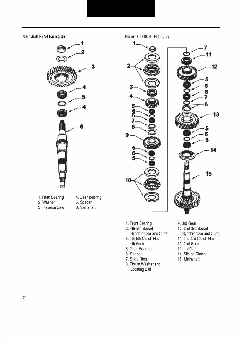
8/11/2019 Información sobre caja de cambios.pdf
http://slidepdf.com/reader/full/informacion-sobre-caja-de-cambiospdf 78/126
74
Transmission OverhaulProcedures-Bench Service
Mainshaft REAR Facing Up Mainshaft FRONT Facing Up
1. Rear Bearing2. Washer3. Reverse Gear
4. Gear Bearing5. Spacer6. Mainshaft
1. Front Bearing2. 4th-5th Speed
Synchronizer and Cups
3. 4th-5th Clutch Hub4. 4th Gear5. Gear Bearing6. Spacer7. Snap Ring8. Thrust Washer and
Locating Ball
9. 3rd Gear10. 2nd-3rd Speed
Synchronizer and Cups
11. 2nd-3rd Clutch Hub12. 2nd Gear13. 1st Gear14. Sliding Clutch15. Mainshaft

8/11/2019 Información sobre caja de cambios.pdf
http://slidepdf.com/reader/full/informacion-sobre-caja-de-cambiospdf 79/126
75
Transmission OverhaulProcedures-Bench Service
How to Disassemble the FS-6305 Mainshaft Assembly
Special Instructions
During disassembly, lay all parts on a clean bench in order of removal to facilitate reassembly.
WARNING:Wear safety glasses when removing snap rings.
Special Tools
Vise with brass jaws or wood blocks
Snap ring pliers
Bearing puller
Procedure - See Mainshaft FRONT Facing Up illustration
1. With mainshaft front facing up, install the mainshaftassembly vertically in a vise.
2. Remove 4th-5th speed synchronizer and cups.
3. Using a puller mounted behind 4th-5th clutch hub,remove hub and bearing.
4. Remove 4th gear, bearings, and spacer.
5. Remove snap ring, thrust washer, and locating ball.6. Remove 3rd gear, bearings, and spacer.
7. Remove 2nd-3rd speed synchronizer and cups.
8. Remove snap ring and 2nd-3rd shift hub.
9. Remove 2nd gear, bearings and spacer.
10. Remove snap ring, thrust washer, and locating ball.
11. Remove 1st gear, bearings, and spacer.
12. Remove 1st speed synchronizer.
Procedure - See Mainshaft REAR Facing Up illustration
13. With mainshaft rear facing up, install the mainshaftassembly vertically in a vise.
14. Using a puller, remove reverse gear, washer, and rearbearing.
15. Remove reverse gear bearings and spacer.

8/11/2019 Información sobre caja de cambios.pdf
http://slidepdf.com/reader/full/informacion-sobre-caja-de-cambiospdf 80/126
76
Transmission OverhaulProcedures-Bench Service
Mainshaft FRONT Facing Up Mainshaft REAR Facing Up
1. Front Bearing2. 4th-5th Speed
Synchronizer and Cups
3. 4th-5th Clutch Hub4. 4th Gear5. Gear Bearing6. Spacer7. Snap Ring8. Thrust Washer and
Locating Ball
9. 3rd Gear10. 2nd-3rd Speed
Synchronizer and Cups
11. 2nd-3rd Clutch Hub12. 2nd Gear13. 1st Gear14. 1st Speed Synchronizer15. Mainshaft
1. Rear Bearing2. Washer3. Reverse Gear4. Gear Bearing5. Spacer6. Mainshaft

8/11/2019 Información sobre caja de cambios.pdf
http://slidepdf.com/reader/full/informacion-sobre-caja-de-cambiospdf 81/126
77
Transmission OverhaulProcedures-Bench Service
How to Assemble the FS-6305 Mainshaft Assembly
Special Instructions
CAUTION:Do not heat the bearing above 275°F (136°C). If possible, use a heat lamp as the source.
Lubricate the gear bearing bores, gear hub faces, split washers, synchronizer friction surfaces, synchronizer cups and the main-shaft with transmission lube as the mainshaft is assembled.
WARNING:Wear safety glasses when installing snap rings.
Special ToolsVise with brass jaws or wood blocksSleeve type bearing driverSnap ring pliers
Procedure - See Mainshaft REAR Facing Up illustration
1. With mainshaft rear facing up, install the mainshaftassembly vertically in a vise.
2. Install reverse gear bearings with spacer between bear-ings.
3. With reverse gear clutching teeth down, install reversegear.
4. Install reverse gear washer. Washer can be installed
either way.5. Use a sleeve type bearing driver or heat lamp and install
the rear mainshaft bearing.
Procedure - See Mainshaft FRONT Facing Up illustration
6. With mainshaft front facing up, install the mainshaftassembly vertically in a vise.
7. Install the 1st-reverse synchronizer.
8. Install 1st gear bearings with spacer between the bear-ings.
9. With 1st gear clutching teeth down, install 1st gear.
10. Install locating ball and washer in mainshaft groove.Washer can be installed either way.
11. Install snap ring in mainshaft groove.
12. Install 2nd gear bearings with spacer between bearings.
13. With 2nd gear clutching teeth up, install 2nd gear.
14. With 2nd-3rd clutch hub stepped face up, install 2nd-3rdclutch hub.
15. Install snap ring in mainshaft groove.
16. Install 2nd-3rd speed synchronizer and cups.
17. Install 3rd gear bearings with spacer between bearings.
18. With 3rd gear clutching teeth down, install 3rd gear.
19. Install locating ball and washer. Washer can be installedeither way.
20. Install snap ring in mainshaft groove.
21. Install 4th gear bearings with spacer between bearings.
22. With 4th gear clutching teeth up, install 4th gear.
23. With 4th-5th clutch hub shoulder end facing down, install4th-5th clutch hub.
24. Install 4th-5th speed synchronizer and cups.
25. Use a sleeve type driver and install the front mainshaftbearing.
Final Check
Make sure the mainshaft gears rotate freely.

8/11/2019 Información sobre caja de cambios.pdf
http://slidepdf.com/reader/full/informacion-sobre-caja-de-cambiospdf 82/126
78
Transmission OverhaulProcedures-Bench Service
Mainshaft REAR Facing Up Mainshaft FRONT Facing Up
1. Rear Bearing2. Washer3. Reverse Gear
4. Gear Bearing5. Spacer6. Mainshaft
1. Front Bearing. 4th-5th Speed
Synchronizer and Cups
. 4th-5th Clutch Hub. 4th Gear5. Gear Bearing6. Spacer. Snap Ring
8. Thrust Washer andLocating Ball
9. 3rd Gear10. 2nd-3rd Speed
Synchronizer and Cups
11. 2nd-3rd Clutch Hub12. 2nd Gear13. 1st Gear14. 1st Speed Synchronizer15. Mainshaft

8/11/2019 Información sobre caja de cambios.pdf
http://slidepdf.com/reader/full/informacion-sobre-caja-de-cambiospdf 83/126
79
Transmission OverhaulProcedures-Bench Service
How to Disassemble the FS-5306/6306 Mainshaft Assembly
Special Instructions
During disassembly, lay all parts on a clean bench in order of removal to facilitate reassembly.
WARNING:Wear safety glasses when removing snap rings.
Special Tools
Vise with brass jaws or wood blocks
Snap ring pliers
Bearing puller
Procedure - See Mainshaft FRONT Facing Up illustration
1. With mainshaft front facing up, install the mainshaftassembly vertically in a vise.
2. Remove 5th-6th speed synchronizer and cups.
3. Using a puller mounted behind 5th-6th clutch hub,remove hub and bearing.
4. Remove 5th gear and bearings.
5. Remove snap ring, thrust washer, and locating ball.6. Remove 4th gear and bearings.
7. Remove 3rd-4th speed synchronizer and cups.
8. Remove snap ring and 3rd-4th clutch hub.
9. Remove 3rd gear and bearings.
10. Remove snap ring, thrust washer, and locating ball.
11. Remove 2nd gear and bearings.
12. Remove 1st-2nd speed synchronizer and cups.
Procedure - See Mainshaft REAR Facing Up illustration
13. With mainshaft rear facing up, install the mainshaftassembly vertically in a vise.
14. Using a puller, remove reverse gear, washer, and rearbearing.
15. Remove reverse gear bearings and sliding clutch.
16. Remove snap ring and clutch hub.
17. Remove 1st gear and bearings.

8/11/2019 Información sobre caja de cambios.pdf
http://slidepdf.com/reader/full/informacion-sobre-caja-de-cambiospdf 84/126
80
Transmission OverhaulProcedures-Bench Service
Mainshaft FRONT Facing Up Mainshaft REAR Facing Up
1. Front Bearing2. 5th-6th Speed
Synchronizer and Cups
3. 5th-6th Clutch Hub4. 5th Gear5. Gear Bearing6. Snap Ring7. Thrust Washer and
Locating Ball8. 4th Gear
9. 3rd-4th SpeedSynchronizer and Cups
10. 3rd-4th Clutch Hub
11. 3rd Gear12. 2nd Gear13. 1st–2nd Speed
Synchronizer and Cups14. Mainshaft
1. Rear Bearing2. Washer3. Reverse Gear4. Gear Bearings5. Sliding Clutch
6. Snap Ring7. 1st Gear Clutch Hub8. 1st Gear9. Mainshaft

8/11/2019 Información sobre caja de cambios.pdf
http://slidepdf.com/reader/full/informacion-sobre-caja-de-cambiospdf 85/126
81
Transmission OverhaulProcedures-Bench Service
How to Assemble the FS-5306/6306 Mainshaft Assembly
Special Instructions
CAUTION:Do not heat the bearing above 275°F (136°C). If possible, use a heat lamp as the source.
Lubricate the gear bearing bores, gear hub faces, synchronizer friction surfaces, synchronizer cups and the mainshaft with trans-mission lube as the mainshaft is assembled.
WARNING:Wear safety glasses when installing snap rings.
Special Tools
Vise with brass jaws or wood blocks
Sleeve type bearing driver
Snap ring pliers
Procedure - See Mainshaft REAR Facing Up illustration
1. With mainshaft rear facing up, install the mainshaftassembly vertically in a vise.
2. Install 1st gear bearings.
3. With 1st gear clutching teeth down, install 1st gear.
4. With reverse gear clutch hub notched teeth facing down,install clutch hub.
5. Install snap ring.
6. With reverse gear sliding clutch counterbore up, installsliding clutch.
7. Install reverse gear bearings.
8. With reverse gear clutching teeth facing down, installreverse gear.
9. Install reverse gear washer. Washer can be installedeither way.
10. Use a sleeve type driver or heat lamp and install the rearmainshaft bearing.
Procedure - See Mainshaft FRONT Facing Up illustration
11. With mainshaft front facing up, install the mainshaftassembly vertically in a vise.
12. Install the 1st-2nd synchronizer and cups.
13. Install 2nd gear bearings.
14. With 2nd gear clutching teeth down, install 2nd gear.
15. Install locating ball and washer in mainshaft groove.Washer can be installed either way.
16. Install snap ring in mainshaft groove.
17. Install 3rd gear bearings.
18. With 3rd gear clutching teeth up, install 3rd gear.
19. With 3rd-4th clutch hub stepped face up, install 3rd-4th
clutch hub.
20. Install snap ring in mainshaft groove.
21. Install 3rd-4th speed synchronizer and cups.
22. Install 4th gear bearings.
23. With 4th gear clutching teeth down, install 3rd gear.

8/11/2019 Información sobre caja de cambios.pdf
http://slidepdf.com/reader/full/informacion-sobre-caja-de-cambiospdf 86/126
82
Transmission OverhaulProcedures-Bench Service
24. Install locating ball and washer. Washer can be installedeither way.
25. Install snap ring in mainshaft groove.
26. Install 5th gear bearings.
27. With 5th gear clutching teeth up, install 5th gear.
28. With 5th-6th clutch hub flat surface facing up, install 5th-6th clutch hub.
29. Install 5th-6th speed synchronizer and cups.
30. Use a sleeve type driver and install the front mainshaftbearing.
Final Check
Make sure the mainshaft gears rotate freely.
Mainshaft REAR Facing Up
1. Rear Bearing2. Washer3. Reverse Gear4. Gear Bearings5. Sliding Clutch
6. Snap Ring7. 1st Gear Clutch Hub8. 1st Gear9. Mainshaft
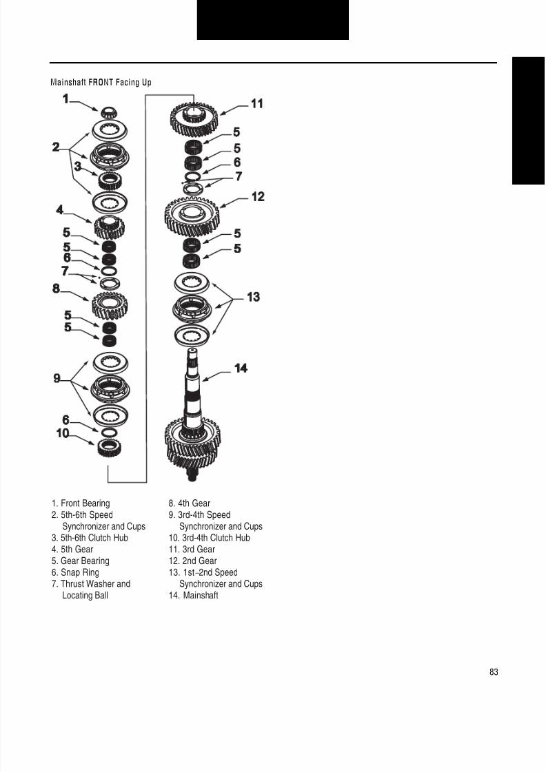
8/11/2019 Información sobre caja de cambios.pdf
http://slidepdf.com/reader/full/informacion-sobre-caja-de-cambiospdf 87/126
83
Transmission OverhaulProcedures-Bench Service
Mainshaft FRONT Facing Up
1. Front Bearing2. 5th-6th Speed
Synchronizer and Cups
3. 5th-6th Clutch Hub4. 5th Gear5. Gear Bearing6. Snap Ring7. Thrust Washer and
Locating Ball
8. 4th Gear9. 3rd-4th Speed
Synchronizer and Cups
10. 3rd-4th Clutch Hub11. 3rd Gear12. 2nd Gear13. 1st–2nd Speed
Synchronizer and Cups14. Mainshaft

8/11/2019 Información sobre caja de cambios.pdf
http://slidepdf.com/reader/full/informacion-sobre-caja-de-cambiospdf 88/126
84
Transmission OverhaulProcedures-Bench Service
How to Disassemble the FS-5406/6406 and FSO-6406 Mainshaft Assembly
Special Instructions
During disassembly, lay all parts on a clean bench in order of removal to facilitate reassembly.
WARNING:Wear safety glasses when removing snap rings.
Special Tools
Vise with brass jaws or wood blocks
Snap ring pliers
Bearing puller
Procedure - See Mainshaft FRONT Facing Up illustration
1. With mainshaft front facing up, install the mainshaftassembly vertically in a vise.
2. Remove 5th-6th speed synchronizer and cups.
3. Using a puller mounted behind 5th-6th clutch hub,remove hub and bearing.
4. Remove 5th gear and bearings.
5. Remove snap ring, thrust washer, and locating ball.6. Remove 4th gear and bearings.
7. Remove 3rd-4th speed synchronizer and cups.
8. Remove snap ring and 3rd-4th clutch hub.
9. Remove 3rd gear and bearings.
10. Remove snap ring, thrust washer, and locating ball.
11. Remove 2nd gear and bearings.
12. Remove 1st-2nd speed synchronizer.
Procedure - See Mainshaft REAR Facing Up illustration
13. With mainshaft rear facing up, install the mainshaftassembly vertically in a vise.
14. Using a puller, remove reverse gear, washer, and rearbearing.
15. Remove reverse gear bearing and sliding clutch.
16. Remove snap ring and clutch hub.
17. Remove 1st gear and bearings.

8/11/2019 Información sobre caja de cambios.pdf
http://slidepdf.com/reader/full/informacion-sobre-caja-de-cambiospdf 89/126
85
Transmission OverhaulProcedures-Bench Service
Mainshaft FRONT Facing Up Mainshaft REAR Facing Up
1. Front Bearing2. 5th-6th Speed
Synchronizer and Cups3. 5th-6th Clutch Hub
4. 5th Gear5. Gear Bearing6. Snap Ring7. Thrust Washer and
Locating Ball8. 4th Gear
9. 3rd-4th SpeedSynchronizer and Cups
10. 3rd-4th Clutch Hub11. 3rd Gear
12. 2nd Gear13. 1st–2nd Speed
Synchronizer14. Mainshaft
1. Rear Bearing2. Washer
3. Reverse Gear4. Gear Bearing5. Sliding Clutch
6. Snap Ring7. 1st Gear Clutch Hub
8. 1st Gear9. Mainshaft

8/11/2019 Información sobre caja de cambios.pdf
http://slidepdf.com/reader/full/informacion-sobre-caja-de-cambiospdf 90/126
86
Transmission OverhaulProcedures-Bench Service
How to Assemble the FS-5406/6406 and FSO-6406 Mainshaft Assembly
Special Instructions
CAUTION:Do not heat the bearing above 275°F (136°C). If possible, use a heat lamp as the source.
Lubricate the gear bearing bores, gear hub faces, synchronizer friction surfaces, synchronizer cups and the mainshaft with trans-mission lube as the mainshaft is assembled.
WARNING:Wear safety glasses when installing snap rings.
Special Tools
Vise with brass jaws or wood blocks
Sleeve type bearing driver
Snap ring pliers
Procedure - See Mainshaft REAR Facing Up illustration
1. With mainshaft rear facing up, install the mainshaftassembly vertically in a vise.
2. Install 1st gear bearings.
3. With 1st gear clutching teeth down, install 1st gear.
4. With reverse gear clutch hub notched teeth facing down,install clutch hub.
5. Install snap ring.
6. With reverse gear sliding tapered clutching teeth facingup, install sliding clutch.
7. Install reverse gear bearing.
8. With reverse gear clutching teeth facing down, installreverse gear.
9. Install reverse gear washer. Washer can be installedeither way.
10. Use a sleeve type driver or heat lamp and install the rearmainshaft bearing.
Procedure - See Mainshaft FRONT Facing Up illustration
11. With mainshaft front facing up, install the mainshaftassembly vertically in a vise.
12. Install the 1st-2nd synchronizer.
a. Slide synchronizer part way on mainshaft to engageone sliding clutch spline teeth on the mainshaftspline teeth.
b. Slide the synchronizer center plate on the mainshaftaligning the three internal fingers with the threemainshaft grooves to get it started.
c. Rotate the 2nd sliding clutch using fingers so itengages the splines on the mainshaft and positioncenter plate axially to the mainshaft spline teeth cen-ter.
13. Install 2nd gear bearings.
14. With 2nd gear clutching teeth down, install 2nd gear.
15. Install locating ball and washer in mainshaft groove.Washer can be installed either way.
16. Install snap ring in mainshaft groove.
17. Install 3rd gear bearings.
18. With 3rd gear clutching teeth up, install 3rd gear.

8/11/2019 Información sobre caja de cambios.pdf
http://slidepdf.com/reader/full/informacion-sobre-caja-de-cambiospdf 91/126
87
Transmission OverhaulProcedures-Bench Service
19. With 3rd-4th clutch hub stepped face up, install 3rd-4thclutch hub.
20. Install snap ring in mainshaft groove.
21. Install 3rd-4th speed synchronizer and cups.
22. Install 4th gear bearings.
23. With 4th gear clutching teeth down, install 3rd gear.
24. Install locating ball and washer. Washer can be installedeither way.
25. Install snap ring in mainshaft groove.
26. Install 5th gear bearings.
27. With 5th gear clutching teeth up, install 5th gear.
28. With 5th-6th clutch hub flat surface facing up, install 5th-6th clutch hub.
29. Install 5th-6th speed synchronizer and cups.
30. Use a sleeve type driver and install the front mainshaftbearing.
Final Check
Make sure the mainshaft gears rotate freely.
Mainshaft REAR Facing Up
1. Rear Bearing2. Washer
3. Reverse Gear4. Gear Bearing5. Sliding Clutch
6. Snap Ring7. 1st Gear Clutch Hub
8. 1st Gear9. Mainshaft
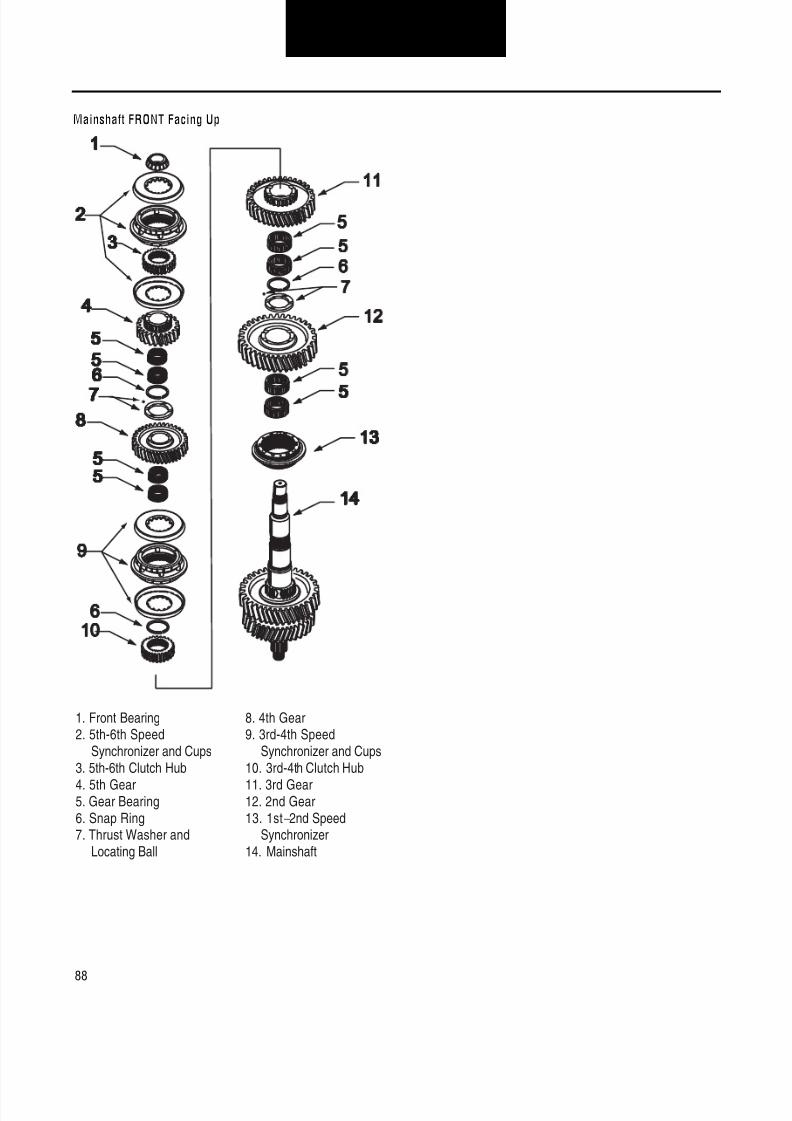
8/11/2019 Información sobre caja de cambios.pdf
http://slidepdf.com/reader/full/informacion-sobre-caja-de-cambiospdf 92/126
88
Transmission OverhaulProcedures-Bench Service
Mainshaft FRONT Facing Up
1. Front Bearing2. 5th-6th Speed
Synchronizer and Cups3. 5th-6th Clutch Hub
4. 5th Gear5. Gear Bearing6. Snap Ring7. Thrust Washer and
Locating Ball
8. 4th Gear9. 3rd-4th Speed
Synchronizer and Cups10. 3rd-4th Clutch Hub
11. 3rd Gear12. 2nd Gear13. 1st–2nd Speed
Synchronizer14. Mainshaft

8/11/2019 Información sobre caja de cambios.pdf
http://slidepdf.com/reader/full/informacion-sobre-caja-de-cambiospdf 93/126
89
Transmission OverhaulProcedures-Bench Service
How to Disassemble the FSO-8406 Mainshaft Assembly
Special Instructions
During disassembly, lay all parts on a clean bench in order of removal to facilitate reassembly.
WARNING:Wear safety glasses when removing snap rings.
Special Tools
Vise with brass jaws or wood blocks
Snap ring pliers
Bearing puller
Procedure - See Mainshaft FRONT Facing Up illustration
1. With mainshaft front facing up, install the mainshaftassembly vertically in a vise.
2. Remove overdrive-5th speed synchronizer and cups.
3. Using a puller mounted behind overdrive-5th clutch hub,remove hub and bearing.
4. Remove overdrive gear and bearings.
5. Remove snap ring, thrust washer, and locating ball.6. Remove 4th gear and bearings.
7. Remove 3rd-4th speed synchronizer and cups.
8. Remove snap ring and 3rd-4th clutch hub.
9. Remove 3rd gear and bearings.
10. Remove snap ring, thrust washer, and locating ball.
11. Remove 2nd gear and bearings.
12. Remove 1st-2nd speed synchronizer:
a. Rotate 2nd sliding clutch with your fingers so that itdisengages the splines on the mainshaft and posi-tion center plate axially to the mainshaft spline teethcenter.
b. Slide the synchronizer center plate off the mainshaftto separate the three internal fingers with the threemainshaft grooves and to disengage the slidingclutch spline teeth from the mainshaft spline teeth.
Procedure - See Mainshaft REAR Facing Up illustration
13. With mainshaft rear facing up, install the mainshaftassembly vertically in a vise.
14. Using a puller, remove reverse gear, washer, and rearbearing.
15. Remove reverse gear bearing and sliding clutch.
16. Remove snap ring and clutch hub.
17. Remove 1st gear and bearings.

8/11/2019 Información sobre caja de cambios.pdf
http://slidepdf.com/reader/full/informacion-sobre-caja-de-cambiospdf 94/126
90
Transmission OverhaulProcedures-Bench Service
Mainshaft FRONT Facing Up Mainshaft REAR Facing Up
1. Front Bearing2. 5th-6th Speed
Synchronizer and Cups3. 5th-6th Clutch Hub
4. 5th Gear5. Gear Bearing6. Snap Ring7. Thrust Washer and
Locating Ball8. 4th Gear
9. 3rd-4th SpeedSynchronizer and Cups
10. 3rd-4th Clutch Hub11. 3rd Gear
12. 2nd Gear13. 1st–2nd Speed
Synchronizer14. Mainshaft
1. Rear Bearing2. Washer
3. Reverse Gear4. Gear Bearings5. Sliding Clutch
6. Snap Ring7. 1st Gear Clutch Hub
8. 1st Gear9. Mainshaft
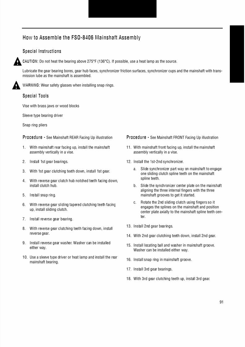
8/11/2019 Información sobre caja de cambios.pdf
http://slidepdf.com/reader/full/informacion-sobre-caja-de-cambiospdf 95/126
91
Transmission OverhaulProcedures-Bench Service
How to Assemble the FSO-8406 Mainshaft Assembly
Special Instructions
CAUTION:Do not heat the bearing above 275°F (136°C). If possible, use a heat lamp as the source.
Lubricate the gear bearing bores, gear hub faces, synchronizer friction surfaces, synchronizer cups and the mainshaft with trans-mission lube as the mainshaft is assembled.
WARNING:Wear safety glasses when installing snap rings.
Special Tools
Vise with brass jaws or wood blocks
Sleeve type bearing driver
Snap ring pliers
Procedure - See Mainshaft REAR Facing Up illustration
1. With mainshaft rear facing up, install the mainshaftassembly vertically in a vise.
2. Install 1st gear bearings.
3. With 1st gear clutching teeth down, install 1st gear.
4. With reverse gear clutch hub notched teeth facing down,install clutch hub.
5. Install snap ring.
6. With reverse gear sliding tapered clutching teeth facingup, install sliding clutch.
7. Install reverse gear bearing.
8. With reverse gear clutching teeth facing down, installreverse gear.
9. Install reverse gear washer. Washer can be installedeither way.
10. Use a sleeve type driver or heat lamp and install the rearmainshaft bearing.
Procedure - See Mainshaft FRONT Facing Up illustration
11. With mainshaft front facing up, install the mainshaftassembly vertically in a vise.
12. Install the 1st-2nd synchronizer.
a. Slide synchronizer part way on mainshaft to engageone sliding clutch spline teeth on the mainshaftspline teeth.
b. Slide the synchronizer center plate on the mainshaftaligning the three internal fingers with the threemainshaft grooves to get it started.
c. Rotate the 2nd sliding clutch using fingers so itengages the splines on the mainshaft and positioncenter plate axially to the mainshaft spline teeth cen-ter.
13. Install 2nd gear bearings.
14. With 2nd gear clutching teeth down, install 2nd gear.
15. Install locating ball and washer in mainshaft groove.Washer can be installed either way.
16. Install snap ring in mainshaft groove.
17. Install 3rd gear bearings.
18. With 3rd gear clutching teeth up, install 3rd gear.
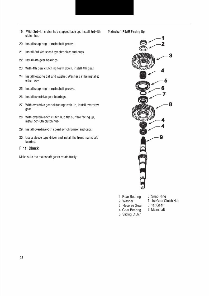
8/11/2019 Información sobre caja de cambios.pdf
http://slidepdf.com/reader/full/informacion-sobre-caja-de-cambiospdf 96/126
92
Transmission OverhaulProcedures-Bench Service
19. With 3rd-4th clutch hub stepped face up, install 3rd-4thclutch hub
20. Install snap ring in mainshaft groove.
21. Install 3rd-4th speed synchronizer and cups.
22. Install 4th gear bearings.
23. With 4th gear clutching teeth down, install 4th gear.
24. Install locating ball and washer. Washer can be installedeither way.
25. Install snap ring in mainshaft groove.
26. Install overdrive gear bearings.
27. With overdrive gear clutching teeth up, install overdrivegear.
28. With overdrive-5th clutch hub flat surface facing up,install 5th-6th clutch hub.
29. Install overdrive-5th speed synchronizer and cups.
30. Use a sleeve type driver and install the front mainshaftbearing.
Final Check
Make sure the mainshaft gears rotate freely.
Mainshaft REAR Facing Up
1. Rear Bearing2. Washer
3. Reverse Gear4. Gear Bearing5. Sliding Clutch
6. Snap Ring7. 1st Gear Clutch Hub8. 1st Gear9. Mainshaft

8/11/2019 Información sobre caja de cambios.pdf
http://slidepdf.com/reader/full/informacion-sobre-caja-de-cambiospdf 97/126
93
Transmission OverhaulProcedures-Bench Service
Mainshaft FRONT Facing Up
1. Front Bearing2. 5th-6th Speed
Synchronizer and Cups3. 5th-6th Clutch Hub
4. 5th Gear5. Gear Bearing6. Snap Ring7. Thrust Washer and
Locating Ball
8. 4th Gear9. 3rd-4th Speed
Synchronizer and Cups10. 3rd-4th Clutch Hub
11. 3rd Gear12. 2nd Gear13. 1st–2nd Speed
Synchronizer14. Mainshaft

8/11/2019 Información sobre caja de cambios.pdf
http://slidepdf.com/reader/full/informacion-sobre-caja-de-cambiospdf 98/126
94
Transmission OverhaulProcedures-Bench Service
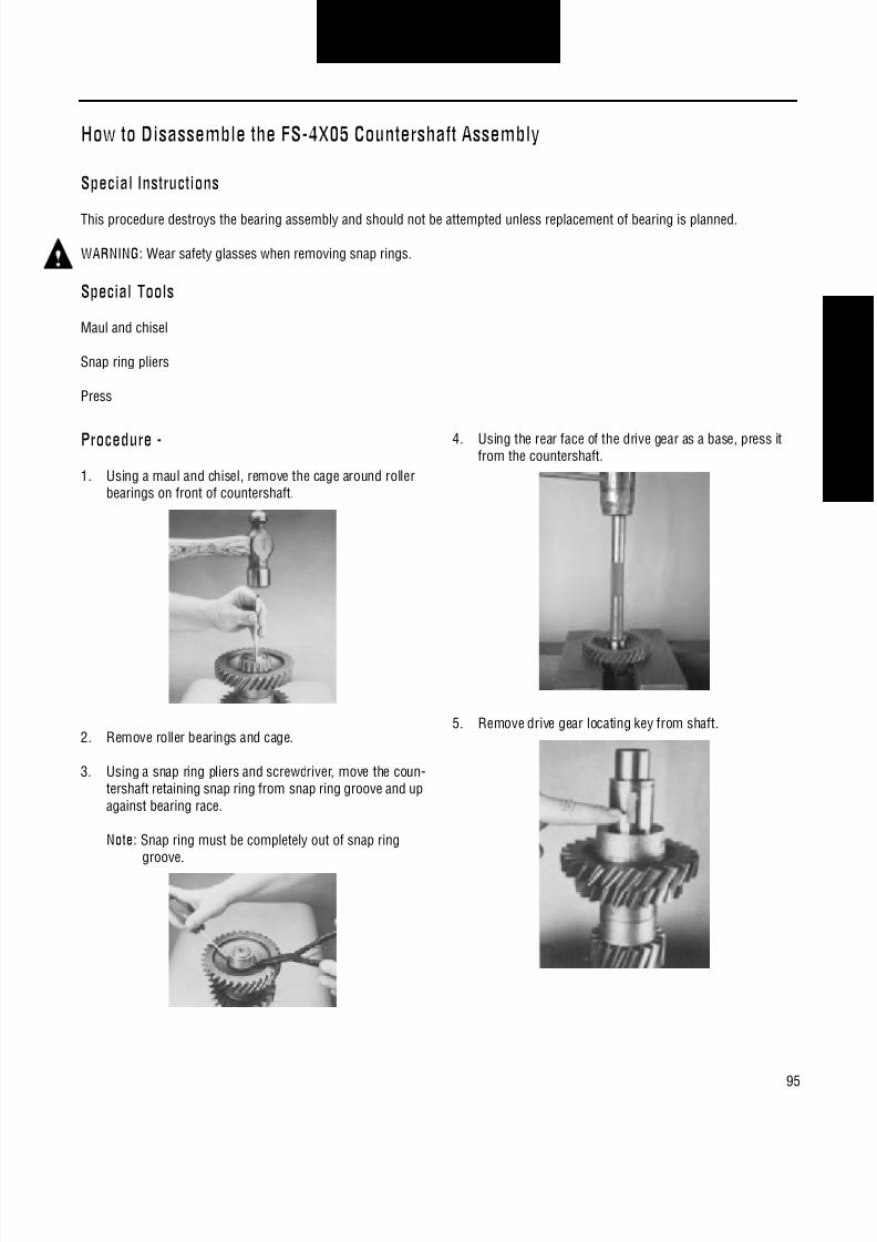
8/11/2019 Información sobre caja de cambios.pdf
http://slidepdf.com/reader/full/informacion-sobre-caja-de-cambiospdf 99/126
95
Transmission OverhaulProcedures-Bench Service
How to Disassemble the FS-4X05 Countershaft Assembly
Special Instructions
This procedure destroys the bearing assembly and should not be attempted unless replacement of bearing is planned.
WARNING:Wear safety glasses when removing snap rings.
Special Tools
Maul and chisel
Snap ring pliers
Press
Procedure -
1. Using a maul and chisel, remove the cage around rollerbearings on front of countershaft.
2. Remove roller bearings and cage.
3. Using a snap ring pliers and screwdriver, move the coun-tershaft retaining snap ring from snap ring groove and upagainst bearing race.
Note: Snap ring must be completely out of snap ringgroove.
4. Using the rear face of the drive gear as a base, press itfrom the countershaft.
5. Remove drive gear locating key from shaft.

8/11/2019 Información sobre caja de cambios.pdf
http://slidepdf.com/reader/full/informacion-sobre-caja-de-cambiospdf 100/126
96
Transmission OverhaulProcedures-Bench Service
6. Using the rear face of 4th speed gear as a base, press itfrom the countershaft.
7. Remove 4th gear key from shaft.
Note: Be sure that 4th-5th speed gear keys have beenremoved before removing 3rd gear from counter-shaft.
8. Using the rear face of 3rd speed gear as a base, press itfrom the countershaft.
9. Using the rear face of 2nd speed gear as a base, press itfrom the countershaft.
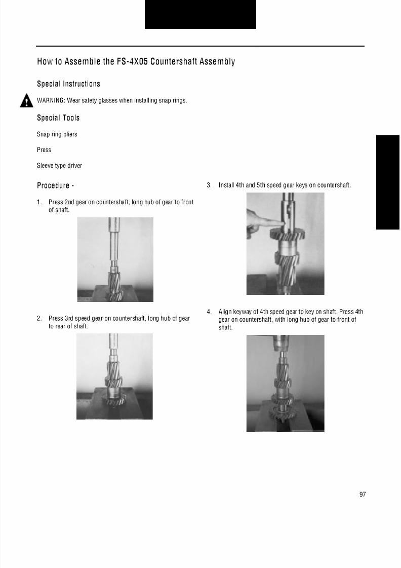
8/11/2019 Información sobre caja de cambios.pdf
http://slidepdf.com/reader/full/informacion-sobre-caja-de-cambiospdf 101/126
97
Transmission OverhaulProcedures-Bench Service
How to Assemble the FS-4X05 Countershaft Assembly
Special Instructions
WARNING:Wear safety glasses when installing snap rings.
Special Tools
Snap ring pliers
Press
Sleeve type driver
Procedure -
1. Press 2nd gear on countershaft, long hub of gear to frontof shaft.
2. Press 3rd speed gear on countershaft, long hub of gearto rear of shaft.
3. Install 4th and 5th speed gear keys on countershaft.
4. Align keyway of 4th speed gear to key on shaft. Press 4thgear on countershaft, with long hub of gear to front ofshaft.

8/11/2019 Información sobre caja de cambios.pdf
http://slidepdf.com/reader/full/informacion-sobre-caja-de-cambiospdf 102/126
98
Transmission OverhaulProcedures-Bench Service
5. Install drive gear key on countershaft.
6. Align keyway of drive gear to key on shaft. Press drive
gear on countershaft with long hub to rear of shaft.
7. Install the countershaft retention snap ring in snap ringgroove at front of countershaft.
8. Using a sleeve type driver, install front countershaft bear-ing.
9. Using a sleeve type driver, install rear countershaft bear-ing.
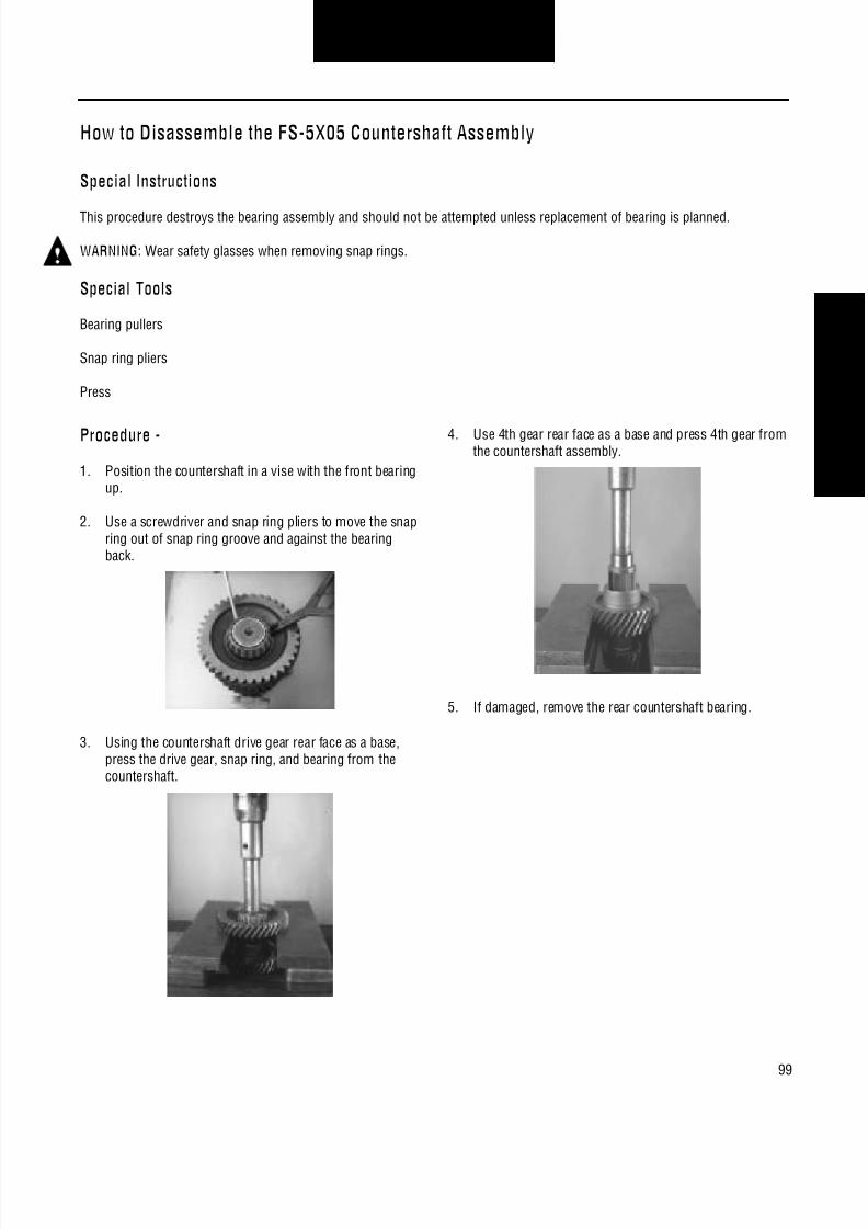
8/11/2019 Información sobre caja de cambios.pdf
http://slidepdf.com/reader/full/informacion-sobre-caja-de-cambiospdf 103/126
99
Transmission OverhaulProcedures-Bench Service
How to Disassemble the FS-5X05 Countershaft Assembly
Special Instructions
This procedure destroys the bearing assembly and should not be attempted unless replacement of bearing is planned.
WARNING:Wear safety glasses when removing snap rings.
Special Tools
Bearing pullers
Snap ring pliers
Press
Procedure -
1. Position the countershaft in a vise with the front bearingup.
2. Use a screwdriver and snap ring pliers to move the snapring out of snap ring groove and against the bearingback.
3. Using the countershaft drive gear rear face as a base,press the drive gear, snap ring, and bearing from thecountershaft.
4. Use 4th gear rear face as a base and press 4th gear fromthe countershaft assembly.
5. If damaged, remove the rear countershaft bearing.

8/11/2019 Información sobre caja de cambios.pdf
http://slidepdf.com/reader/full/informacion-sobre-caja-de-cambiospdf 104/126
100
Transmission OverhaulProcedures-Bench Service
How to Assemble the FS-5X05 Countershaft Assembly
Special Instructions
CAUTION:Do not heat the bearing above 275°F (136°C). If possible, use a heat lamp as the source.
WARNING:Wear safety glasses when installing snap rings.
Special Tools
Snap ring pliers
Press
Heat lamp
Procedure -
1. With 4th gear long hub to shaft front, align 4th gear key-way with shaft key, position the gear and shaft in thepress. Press 4th gear into place.
2. With drive gear long hub to shaft rear, align drive gearkeyway with shaft key, position the gear and shaft in thepress. Press drive gear into place.
3. Install the drive gear retaining snap ring in groove.
4. Heat and install the front countershaft bearing.
5. If removed, heat and install the rear countershaft bearing.
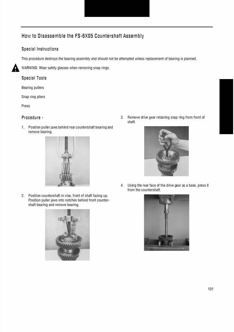
8/11/2019 Información sobre caja de cambios.pdf
http://slidepdf.com/reader/full/informacion-sobre-caja-de-cambiospdf 105/126
101
Transmission OverhaulProcedures-Bench Service
How to Disassemble the FS-6X05 Countershaft Assembly
Special Instructions
This procedure destroys the bearing assembly and should not be attempted unless replacement of bearing is planned.
WARNING:Wear safety glasses when removing snap rings.
Special Tools
Bearing pullers
Snap ring pliers
Press
Procedure -
1. Position puller jaws behind rear countershaft bearing andremove bearing.
2. Position countershaft in vise, front of shaft facing up.Position puller jaws into notches behind front counter-shaft bearing and remove bearing.
3. Remove drive gear retaining snap ring from front ofshaft.
4. Using the rear face of the drive gear as a base, press itfrom the countershaft.
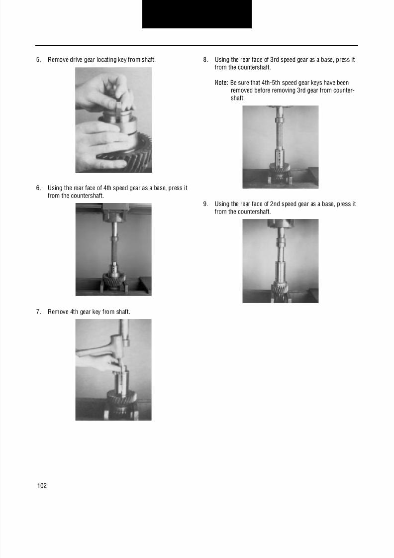
8/11/2019 Información sobre caja de cambios.pdf
http://slidepdf.com/reader/full/informacion-sobre-caja-de-cambiospdf 106/126
102
Transmission OverhaulProcedures-Bench Service
5. Remove drive gear locating key from shaft.
6. Using the rear face of 4th speed gear as a base, press it
from the countershaft.
7. Remove 4th gear key from shaft.
8. Using the rear face of 3rd speed gear as a base, press itfrom the countershaft.
Note: Be sure that 4th-5th speed gear keys have beenremoved before removing 3rd gear from counter-
shaft.
9. Using the rear face of 2nd speed gear as a base, press itfrom the countershaft.

8/11/2019 Información sobre caja de cambios.pdf
http://slidepdf.com/reader/full/informacion-sobre-caja-de-cambiospdf 107/126
103
Transmission OverhaulProcedures-Bench Service
How to Assemble the FS-6X05 Countershaft Assembly
Special Instructions
CAUTION:Do not heat the bearing above 275°F (136°C). If possible, use a heat lamp as the source.
WARNING:Wear safety glasses when installing snap rings.
Special Tools
Snap ring pliers
Press
Sleeve type driver
Procedure -
1. With 2nd gear long hub to shaft front, position the gearand shaft in the press. Press 2nd gear into place.
2. With 3rd gear long hub to shaft front, position the gearand shaft in the press. Press 3rd gear into place.
3. Install 4th and drive gear keys on countershaft.
4. With 4th gear long hub to shaft front, align 4th gear key-way with shaft key, position the gear and shaft in thepress. Press 4th gear into place.

8/11/2019 Información sobre caja de cambios.pdf
http://slidepdf.com/reader/full/informacion-sobre-caja-de-cambiospdf 108/126

8/11/2019 Información sobre caja de cambios.pdf
http://slidepdf.com/reader/full/informacion-sobre-caja-de-cambiospdf 109/126
105
Transmission OverhaulProcedures-Bench Service
How to Disassemble the FS-5306/6306/5406/6406 and FSO-6406/8406 CountershaftAssembly
Special Instructions
As the individual countershaft gears are pressed from the shaft, make sure to remove the corresponding gear key.
WARNING:Wear safety glasses when removing snap rings.
Special Tools
Bearing pullers
Snap ring pliers
Press
Vise with brass jaws or wood blocks
Procedure -
1. Position countershaft in a vise with the front bearing up.
2. Position puller jaws into the countershaft bearingnotches and remove the bearing.
3. Remove the drive gear retaining snap ring.
4. Use drive gear rear face as a base and press drive gearfrom the countershaft assembly.

8/11/2019 Información sobre caja de cambios.pdf
http://slidepdf.com/reader/full/informacion-sobre-caja-de-cambiospdf 110/126
106
Transmission OverhaulProcedures-Bench Service
5. From the shaft, remove the drive gear locating key andspacer.
6. Use 5th gear rear face as a base and press 5th gear fromthe countershaft assembly.
7. From the shaft, remove 5th gear locating key.
8. Use 4th gear rear face as a base and press 4th gear fromthe countershaft assembly.
9. Use 3rd gear rear face as a base and press 3rd gear fromthe countershaft assembly.
10. If damaged, remove the countershaft bearing.

8/11/2019 Información sobre caja de cambios.pdf
http://slidepdf.com/reader/full/informacion-sobre-caja-de-cambiospdf 111/126
107
Transmission OverhaulProcedures-Bench Service
How to Assemble the FS-5306/6306/5406/6406 and FSO-6406/8406 CountershaftAssembly
Special Instructions
CAUTION:Do not heat the bearing above 275°F (136°C). If possible, use a heat lamp as the source.
WARNING:Wear safety glasses when installing snap rings.
Special Tools
Snap ring pliers
Press
Sleeve type driver
Procedure -
1. With 3rd gear splined end hub to shaft front, position thegear and shaft in the press. Press 3rd gear into place.
2. With 4th gear splined end hub to shaft rear, position thegear and shaft in the press. Press 4th gear into place.
3. Install 5th and drive gear keys on the countershaft.
4. With 5th gear long hub to shaft front, align 5th gear key-way with shaft key, position the gear and shaft in thepress. Press 5th gear into place.

8/11/2019 Información sobre caja de cambios.pdf
http://slidepdf.com/reader/full/informacion-sobre-caja-de-cambiospdf 112/126
108
Transmission OverhaulProcedures-Bench Service
5. With drive gear long hub to shaft rear, align drive gearkeyway with shaft key, position the gear and shaft in thepress. Press the drive gear into place.
6. Install drive gear retaining snap ring in countershaft frontgroove.
7. Using a sleeve type driver or heat lamp and install thefront countershaft bearing.
8. Using a sleeve type driver or heat lamp and install therear countershaft bearing.
Final Check
Make sure all gears are pressed into place.
Make sure the countershaft bearings are installed.

8/11/2019 Información sobre caja de cambios.pdf
http://slidepdf.com/reader/full/informacion-sobre-caja-de-cambiospdf 113/126
109
Transmission OverhaulProcedures-Bench Service
How to Install the Reverse Idler Gear Assembly For All Models Except FS-5306/6306
Procedure -
1. Coat inside diameter of reverse idler with a high qualitygrease, and insert the spacer in the reverse idler gear.
2. On both sides of the reverse idler spacer, install the
coated bearings in reverse idler gear.
3. Use grease on reverse idler thrust washers to hold inplace.
4. Position tangs of washers to align grooves of housingand install the reverse idler assembly in housing.
5. Install the reverse idler assembly in housing.
6. Insert the idler shaft into the case bore, line up idler shaftlock groove with lockscrew hole.
7. Position reverse idler retainer. Tighten the capscrew to
the 20-25 lbs. ft. (27.1-33.8 N•m) of torque.
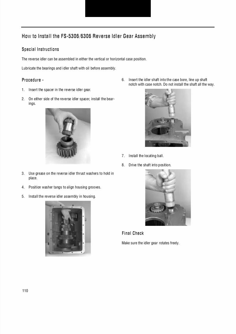
8/11/2019 Información sobre caja de cambios.pdf
http://slidepdf.com/reader/full/informacion-sobre-caja-de-cambiospdf 114/126
110
Transmission OverhaulProcedures-Bench Service
How to Install the FS-5306/6306 Reverse Idler Gear Assembly
Special Instructions
The reverse idler can be assembled in either the vertical or horizontal case position.
Lubricate the bearings and idler shaft with oil before assembly.
Procedure -
1. Insert the spacer in the reverse idler gear.
2. On either side of the reverse idler spacer, install the bear-ings.
3. Use grease on the reverse idler thrust washers to hold inplace.
4. Position washer tangs to align housing grooves.
5. Install the reverse idler assembly in housing.
6. Insert the idler shaft into the case bore, line up shaftnotch with case notch. Do not install the shaft all the way.
7. Install the locating ball.
8. Drive the shaft into position.
Final CheckMake sure the idler gear rotates freely.

8/11/2019 Información sobre caja de cambios.pdf
http://slidepdf.com/reader/full/informacion-sobre-caja-de-cambiospdf 115/126
111
Transmission OverhaulProcedures-Bench Service
How to Install the Countershaft Assembly
Procedure -
1. Insert idler shaft through case and idler gear bearings.Line up idler shaft lock groove with lockscrew hole andinstall capscrew, and reverse idler retainer and tightenthe capscrew to the recommended torque.
2. Carefully lower countershaft into case.
3. Turn transmission case on end. Position countershaftassembly into front bearing race.
4. Install countershaft rear bearing race into case.
5. Temporarily install new shims over countershaft rearbearing cup.
6. Install countershaft rear bearing cover and four cap-screws. Tighten capscrews to recommended torque.
7. Rotate countershaft to seat bearings and races. Positiondial indicator as shown, lift countershaft to measure endplay.

8/11/2019 Información sobre caja de cambios.pdf
http://slidepdf.com/reader/full/informacion-sobre-caja-de-cambiospdf 116/126
112
Transmission OverhaulProcedures-Bench Service
8. Add shims for more end play and remove shims for lessend play.
Note: Once end play is correct remove bearing cover andapply a light coat of Loctite 510 to face of retainer
and both sides of shims. Coat threads of cap-screws with Loctite 262 and re-torque.
End Play by Model
9. If fill plug and drain plugs were removed, coat threads ofplugs with Loctite 262 and install to proper recom-mended torque setting.
Model Countershaft End Play
FS-4X05 .002-.008 in (0.050-0.20 mm min)
FS-5205 .002-.008 in (0.050-0.20 mm min)
FS-6205/6305 .006-.010 (0.15-0.25 mm min)
FS-5306/6306 .006-.010 (0.15-0.25 mm min)FS-5406/6406 .006-.010 (0.15-0.25 mm min)
FSO-8406 .006-.010 (0.15-0.25 mm min)

8/11/2019 Información sobre caja de cambios.pdf
http://slidepdf.com/reader/full/informacion-sobre-caja-de-cambiospdf 117/126
113
Transmission OverhaulProcedures-Bench Service
How to Install the Mainshaft Assembly
Special Instructions
The countershaft must be installed first.
Make sure the synchronizer cups on the mainshaft front end stay in position as the mainshaft is lowered into the case.
Top of the rear bearing cover is marked for proper installation.
Setting end play is done in the vertical position.
When setting end play the rear bearing cover, yoke and output shaft nut will be installed, removed, and installed again.
After end play is correct, apply a light coat of Eaton/ Fuller sealant #71233 or equivalent to both sides of the shims, case, andcover before assembly.
Special Tools
Sling and hoist
Flanged driver
Dial indicator
Procedure -
1. Using a sling around the mainshaft.
2. Carefully lower the mainshaft assembly into the casewhile guiding the output shaft through the rear case bore.
3. Remove the sling and place synchronizer in neutral.
4. Coat output shaft bearing cover oil seal outer diameterwith Eaton/Fuller Sealant #71217 or equivalent.
5. If removed, install the oil seal with flanged driver.
6. If removed, install output shaft bearing race.
7. Temporarily position shims on the rear bearing mountingsurface.

8/11/2019 Información sobre caja de cambios.pdf
http://slidepdf.com/reader/full/informacion-sobre-caja-de-cambiospdf 118/126
114
Transmission OverhaulProcedures-Bench Service
8. Position the rear bearing cover over the shims.
9. Install the retaining nuts and tighten to 60-70 lbs. ft.(81.3-94.9 N•m) of torque.
10. Make sure the mainshaft rotates freely.
Final Check
Make sure nuts are properly torqued.
Make sure the output shaft rotates.
Make sure to set end play, refer to Setting End Play ProcedureFor All Models Except FS-5205 on page 117 or Setting EndPlay Procedure For FS-5205 on page 119.

8/11/2019 Información sobre caja de cambios.pdf
http://slidepdf.com/reader/full/informacion-sobre-caja-de-cambiospdf 119/126
115
Transmission OverhaulProcedures-Bench Service
How to Install the Input Shaft Assembly
Special Tools
Sleeve type driver
Flanged driver
Procedure -
1. Using the proper size sleeve type driver, install the fronttapered bearing on the input shaft.
2. Install the input shaft by aligning the clutching teeth onthe 5th-6th speed synchronizer and input shaft clutchingteeth.
3. Coat the outer diameter of the front bearing cover oil sealwith a light coat of Loctite #510. Install the oil seal with aflanged driver.
4. Install a new input shaft bearing race in the front bearingcover.
5. Install the front bearing cover and gasket, align the coverand gasket with the six capscrew holes in the case. Installthe six capscrews and tighten to the recommendedtorque.
Note: The top of the front bearing cover is marked "TOP"for proper installation.

8/11/2019 Información sobre caja de cambios.pdf
http://slidepdf.com/reader/full/informacion-sobre-caja-de-cambiospdf 120/126
116
Transmission OverhaulProcedures-Bench Service
6. Install the speedometer drive or rotor on the output shaft.

8/11/2019 Información sobre caja de cambios.pdf
http://slidepdf.com/reader/full/informacion-sobre-caja-de-cambiospdf 121/126
117
Transmission OverhaulProcedures-Bench Service
Setting End Play Procedure For All Models Except FS-5205
Special Instructions
Setting end play is done in a vertical position.
When setting end play the rear bearing cover, yoke and output shaft nut will be installed, removed, and installed again.
After end play is correct, apply a light coat of Eaton/Fuller sealant #71233 or equivalent to both sides of the shims, case, andcover before assembly.
Special Tools
Dial indicator
Procedure -
1. Place transmission in a vertical position with front enddown.
2. Temporarily install the yoke and output shaft nut. For partnumber 21937, tighten nut to 300-350 lbs. ft. (406-475N•m) of torque. For part number 4304690, tighten nut to500 lbs. ft. (678 N•m) of torque.
3. Rotate the output shaft and mainshaft six (6) times clock-wise and six (6) times counterclockwise to seat bearingsand races.
4. Position the dial indicator on the output shaft end.
5. Pry up on the output shaft to measure the end play. Endplay must be set per chart.
End Play by Model
6. End play must be set per table.
7. Remove shims for less end play, add shims for more endplay.
8. Remove output shaft nut, yoke and rear bearing cover,coat the shims.
Model Mainshaft End Play
FS-4X05 .008-.012 in (0.20-0.30 mm)
FS-5205 .008-.012 in (0.20-0.30 mm)
FS-6205/6305 .006-.010 in (0.15-0.25 mm)
FS-5306/6306 .006-.010 in (0.15-0.25 mm)
FS-5406/6406 .006-.010 in (0.15-0.25 mm)
FSO-8406 .006-.010 in (0.15-0.25 mm)

8/11/2019 Información sobre caja de cambios.pdf
http://slidepdf.com/reader/full/informacion-sobre-caja-de-cambiospdf 122/126
118
Transmission OverhaulProcedures-Bench Service
9. Position shims and rear bearing cover on case, rear bear-ing cover top is marked for proper positioning.
10. Install the retaining nuts, tighten to 60-70 lbs. ft. (81.3-94.9 N•m) of torque.
Final Check
Make sure nuts are properly torqued.
Make sure the output shaft rotates.
Make sure end play is within specification.

8/11/2019 Información sobre caja de cambios.pdf
http://slidepdf.com/reader/full/informacion-sobre-caja-de-cambiospdf 123/126

8/11/2019 Información sobre caja de cambios.pdf
http://slidepdf.com/reader/full/informacion-sobre-caja-de-cambiospdf 124/126
120
Transmission OverhaulProcedures-Bench Service
11. Pry up on the output shaft to measure the end play.
12. End play must be set per table.
End Play by Model
13. Remove shims for less end play, add shims for more endplay.
14. After the correct end play is set, remove the front bearingcover and shims. Coat both sides of the shims with alight coat of Loctite #510 or equivalent.
15. Position the shims and the front bearing cover.
16. Install the cover capscrews. Tighten to 15-20 lbs. ft.(20.3-27.1 N•m) of torque.
Final Check
Make sure nuts and capscrews are properly torqued.
Make sure the output shaft rotates.
Model Mainshaft End Play
FS-4205 .008-.012 in (0.20-0.30 mm)
FS-5205 .008-.012 in (0.20-0.30 mm)
FS-6205/6305 .006-.010 in (0.15-0.25 mm)
FS-5306/6306 .006-.010 in (0.15-0.25 mm)
FS-5406/6406 .006-.010 in (0.15-0.25 mm)
FSO-8406 .006-.010 in (0.15-0.25 mm)

8/11/2019 Información sobre caja de cambios.pdf
http://slidepdf.com/reader/full/informacion-sobre-caja-de-cambiospdf 125/126

8/11/2019 Información sobre caja de cambios.pdf
http://slidepdf.com/reader/full/informacion-sobre-caja-de-cambiospdf 126/126