influence of the twist drill geometrical … · twist drill, cutting element, tool ... influence of...
TRANSCRIPT
INFLUENCE OF THE TWIST DRILL
GEOMETRICAL PARAMETERS ON MAGNITUDE OF
CUTTING FORCESJ. Sklenicka, I. Cesákova
Department of Machining Technology, University of West Bohemia,Pilsen, Czech Republic
e-mail: [email protected]
The article is focused on decomposition of cutting forces on cuttingelements. The cutting forces are described via geometrical parameters
of the twist drill. In the course of experiments magnitude of the feedforce and the torque were measured. The shape of the chip
was the next evaluated parameter.
Keywordstwist drill, cutting element, tool geometry, cutting element, measuring
1. IntroductionMonitoring the whole cutting edge of a twist drill is not enough nowadays. The main cause is the variable magnitude of the tool geometry depending on the point of distance from the drill axis. It must be divided into single elements. More accurate informa-tion about the influence of the geometrical parameters on the load magnitude can be obtained by dividing the cutting edge. The cut-ting edge is divided into elements of identical size and they are es-sential for our experiments. The cutting elements have an exact po-sition opposite the drill axis and have defined tool geometry. The load magnitude (thrust forces, passive forces and cutting torque) on the elements is monitored.
Furthermore, the supporting parameters are monitored to under-stand the cutting process. The supporting parameters are mainly the magnitude and shape of the chips, roughness of the machining surface, acoustic behaviour, etc [Zetek 2005].
A practical comparison of twist drills with the shape of the cutting edge and the line cutting edge is carried out in the practical part of the experiment. Twist drills are evaluated according to the shape of the chip and the feed force and torque magnitude [Zetek 2005].
2. Decomposition of forces on cutting element 2.1 Cutting element definitionWhen we decomposed the cutting force on parts of the cutting edge (cutting elements) we found that the force magnitude on the element is strongly under the influence of the diameter location on the cutting edge. The element is marked as CE (cutting element). The CE is defined as the exact part of the cutting edge which has defined cutting geometry, location on the cutting edge and dis-tance from the drill axis.
The experiments were created on the principle of drilling pre-drilled holes with testing drills (one predrilled hole is equal to one cutting element). The cutting edge is divided into single cutting ele-ments using this principle. The magnitude and number of elements depend on the graduation of the drills which are used to prepare the workpiece [Sadilek 2008].
The range of the cutting edge was decomposed on twelve elements which have one length. It means that we used predrilled holes from
0.5 mm to 6 mm by step 0.5 mm. The holes were drilled to cylindrical boards. The board diameter was 120 mm and every board was 36 mm thick. For every predrilled holes and tested tool were made five repetitions. For a better introduction to tested drill was used for predrilled hole straight plate which had the function of drill guide.
2.2 Principle of force decomposition on CEWe get out from assumption that the cutting forces are decomposed on CE. We can decompose the resultant cutting force for the whole drill into the resultant cutting forces for the cutting elements. They can be decomposed to a single component to the tangential, radial and axial direction. The tangential (cutting) component is replaced by the cutting torque which is measured and evaluated [Sadilek 2008].
The measured data have a relative character only, because they do not describe directly the cutting force magnitude but only the magnitude of the cutting force for several elements. The absolute force magnitude for CE must be calculated from another equation (see formula 1).
(1)
Where:Fxi is a random component of the resultant cutting force on the ele-ment i [N], FxNi is a randomly measured component of the resultant cutting force on element i [N], FxNi+1 is a randomly measured com-ponent of the resultant cutting force on element i+1 [N], i is the serial number representing the size of the predrilled hole in mm (if i is equal to 0 the predrilled hole diameter equals 0 mm).
The validity condition for the previous relation is that the sum of all the elementary loads must be equal to the resultant load of the tool. Respectively the sum of all elementary components must be equal to the sum of all components for the resultant cutting force.
(2)
Where:Fx is a random component of the resultant cutting force [N], Fxi is a random component of the resultant cutting force on the element i [N],
3. Measuring of forces on cutting elements3.1 Tested toolsTwist drills were selected for the experiments. The drills are 12 mm in diameter and they are made from sintered carbide deposited with a commercial thin layer. Two drills were used for the whole experiment.
They have different geometrical parameters [Zetek 2005]. The first drill has a straight cutting edge and the second drill has a cutting edge shaped. The shapes of all the cutting edges are shown in Figure 2.
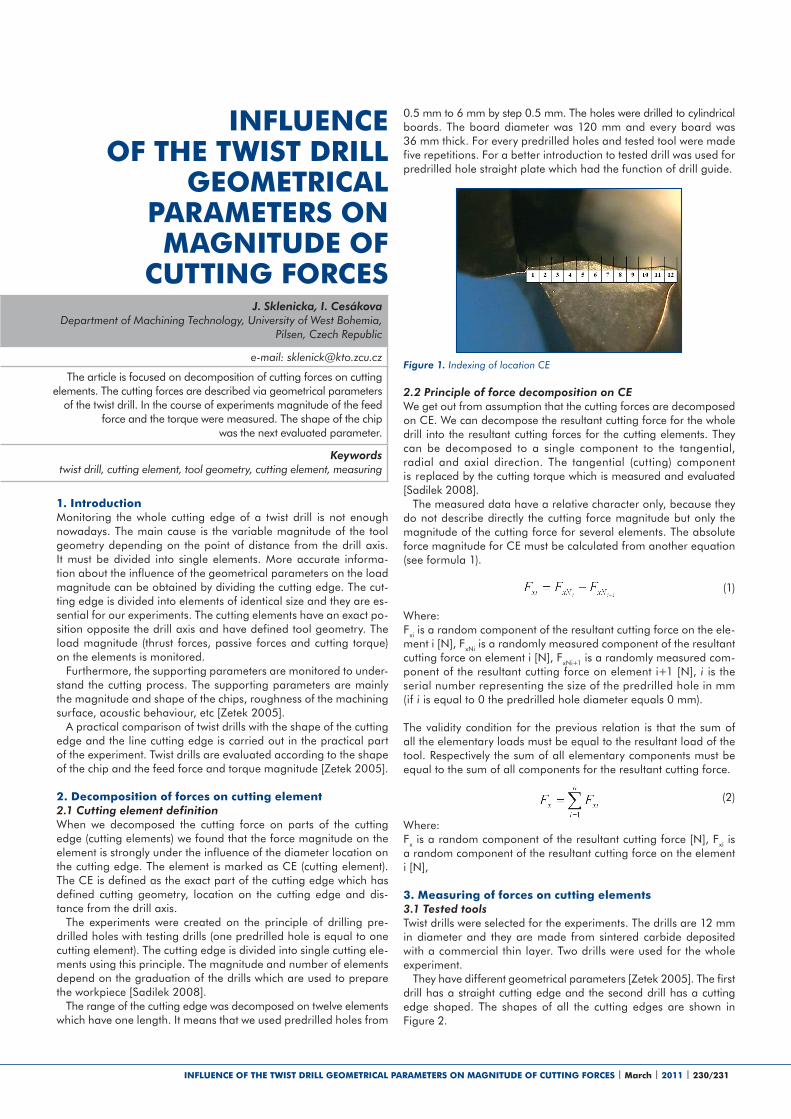
Figure 1. Indexing of location CE
INFLUENCE OF THE TWIST DRILL GEOMETRICAL PARAMETERS ON MAGNITUDE OF CUTTING FORCES | March | 2011 | 230/231
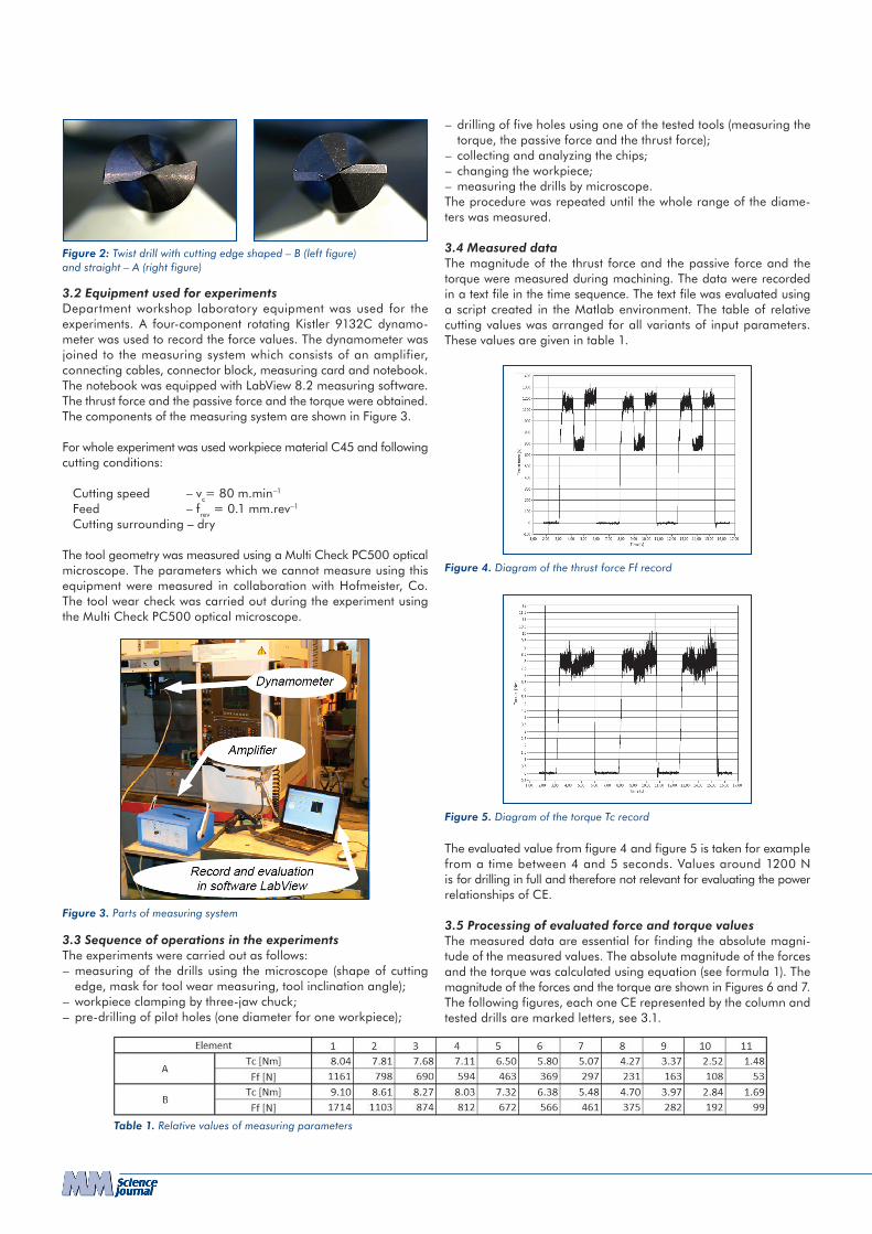
3.2 Equipment used for experimentsDepartment workshop laboratory equipment was used for the experiments. A four-component rotating Kistler 9132C dynamo-meter was used to record the force values. The dynamometer was joined to the measuring system which consists of an amplifier, connecting cables, connector block, measuring card and notebook. The notebook was equipped with LabView 8.2 measuring software. The thrust force and the passive force and the torque were obtained. The components of the measuring system are shown in Figure 3.
For whole experiment was used workpiece material C45 and following cutting conditions:
Cutting speed – vc= 80 m.min–1
Feed – frev = 0.1 mm.rev–1
Cutting surrounding – dry
The tool geometry was measured using a Multi Check PC500 optical microscope. The parameters which we cannot measure using this equipment were measured in collaboration with Hofmeister, Co. The tool wear check was carried out during the experiment using the Multi Check PC500 optical microscope.
3.3 Sequence of operations in the experimentsThe experiments were carried out as follows:– measuring of the drills using the microscope (shape of cutting
edge, mask for tool wear measuring, tool inclination angle);– workpiece clamping by three-jaw chuck;– pre-drilling of pilot holes (one diameter for one workpiece);
– drilling of five holes using one of the tested tools (measuring the torque, the passive force and the thrust force);
– collecting and analyzing the chips;– changing the workpiece;– measuring the drills by microscope.The procedure was repeated until the whole range of the diame-ters was measured.
3.4 Measured dataThe magnitude of the thrust force and the passive force and the torque were measured during machining. The data were recorded in a text file in the time sequence. The text file was evaluated using a script created in the Matlab environment. The table of relative cutting values was arranged for all variants of input parameters. These values are given in table 1.
The evaluated value from figure 4 and figure 5 is taken for example from a time between 4 and 5 seconds. Values around 1200 N is for drilling in full and therefore not relevant for evaluating the power relationships of CE.
3.5 Processing of evaluated force and torque valuesThe measured data are essential for finding the absolute magni-tude of the measured values. The absolute magnitude of the forces and the torque was calculated using equation (see formula 1). The magnitude of the forces and the torque are shown in Figures 6 and 7. The following figures, each one CE represented by the column and tested drills are marked letters, see 3.1.
Figure 2: Twist drill with cutting edge shaped – B (left figure) and straight – A (right figure)
Figure 3. Parts of measuring system
Figure 4. Diagram of the thrust force Ff record
Figure 5. Diagram of the torque Tc record
Table 1. Relative values of measuring parameters
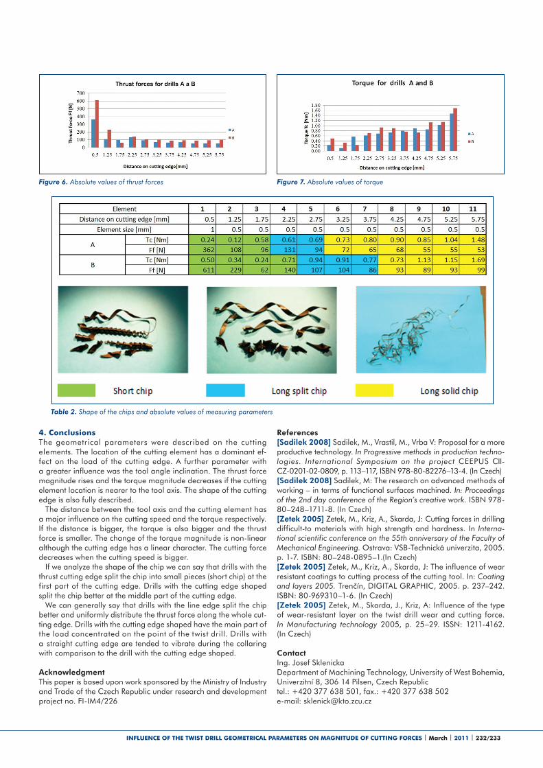
4. ConclusionsThe geometrical parameters were described on the cut ting elements. The location of the cutting element has a dominant ef-fect on the load of the cutting edge. A further parameter with a greater influence was the tool angle inclination. The thrust force magnitude rises and the torque magnitude decreases if the cutting element location is nearer to the tool axis. The shape of the cutting edge is also fully described.
The distance between the tool axis and the cutting element has a major influence on the cutting speed and the torque respectively. If the distance is bigger, the torque is also bigger and the thrust force is smaller. The change of the torque magnitude is non-linear although the cutting edge has a linear character. The cutting force decreases when the cutting speed is bigger.
If we analyze the shape of the chip we can say that drills with the thrust cutting edge split the chip into small pieces (short chip) at the first part of the cutting edge. Drills with the cutting edge shaped split the chip better at the middle part of the cutting edge.
We can generally say that drills with the line edge split the chip better and uniformly distribute the thrust force along the whole cut-ting edge. Drills with the cutting edge shaped have the main part of the load concentrated on the point of the twist drill. Drills with a straight cutting edge are tended to vibrate during the collaring with comparison to the drill with the cutting edge shaped.
AcknowledgmentThis paper is based upon work sponsored by the Ministry of Industry and Trade of the Czech Republic under research and development project no. FI-IM4/226
Table 2. Shape of the chips and absolute values of measuring parameters
Figure 6. Absolute values of thrust forces Figure 7. Absolute values of torque
References[Sadilek 2008] Sadilek, M., Vrastil, M., Vrba V: Proposal for a more productive technology. In Progressive methods in production techno- logies. International Symposium on the project CEEPUS CII-CZ-0201-02-0809, p. 113–117, ISBN 978-80-82276–13-4. (In Czech) [Sadilek 2008] Sadilek, M: The research on advanced methods of working – in terms of functional surfaces machined. In: Proceedings of the 2nd day conference of the Region’s creative work. ISBN 978-80–248–1711-8. (In Czech) [Zetek 2005] Zetek, M., Kriz, A., Skarda, J: Cutting forces in drilling difficult-to materials with high strength and hardness. In Interna-tional scientific conference on the 55th anniversary of the Faculty of Mechanical Engineering. Ostrava: VSB-Technická univerzita, 2005. p. 1-7. ISBN: 80–248-0895–1.(In Czech) [Zetek 2005] Zetek, M., Kriz, A., Skarda, J: The influence of wear resistant coatings to cutting process of the cutting tool. In: Coating and layers 2005. Trenčín, DIGITAL GRAPHIC, 2005. p. 237–242. ISBN: 80-969310–1-6. (In Czech) [Zetek 2005] Zetek, M., Skarda, J., Kriz, A: Influence of the type of wear-resistant layer on the twist drill wear and cutting force. In Manufacturing technology 2005, p. 25–29. ISSN: 1211-4162. (In Czech)
ContactIng. Josef Sklenicka Department of Machining Technology, University of West Bohemia, Univerzitní 8, 306 14 Pilsen, Czech Republictel.: +420 377 638 501, fax.: +420 377 638 502e-mail: [email protected]
INFLUENCE OF THE TWIST DRILL GEOMETRICAL PARAMETERS ON MAGNITUDE OF CUTTING FORCES | March | 2011 | 232/233