influence of grating parameters on the linewidths of external-cavity diode lasers
TRANSCRIPT

Influence of grating parameters on the linewidths ofexternal-cavity diode lasers
Huanqian Loh, Yu-Ju Lin, Igor Teper, Marko Cetina, Jonathan Simon, James K. Thompson,and Vladan Vuletic
We investigate experimentally the influence of the grating reflectivity, grating resolution, and diode facetantireflection (AR) coating on the intrinsic linewidth of an external-cavity diode laser built with adiffraction grating in a Littrow configuration. Grating lasers at 399, 780, and 852 nm are determined tohave typical linewidths between 250 and 600 kHz from measurements of their frequency noise powerspectral densities. The linewidths are little affected by the presence of an AR coating on the diode facetbut narrow as the grating reflectivity and grating resolution are increased, with the resolution exertinga greater effect. We also use frequency noise measurements to characterize a laser mount with improvedmechanical stability. © 2006 Optical Society of America
OCIS codes: 140.2020, 140.3600, 050.1950.
1. Introduction
Diode lasers have vast applications in atomic physics,because of their reliability, easy tunability, and lowcost.1,2 Diode lasers alone, however, have linewidthsof �20 MHz,3 which are often too broad for manipu-lating atoms and are typically not tunable to everywavelength of interest. Optical feedback, achieved byadding an external-cavity element such as a diffrac-tion grating, not only enhances the wavelength tun-ability, but also reduces the intrinsic linewidth tobelow 1 MHz.1–3
Linewidths of external-cavity diode lasers havebeen extensively studied both theoretically4–13 andexperimentally.14–19 Theoretical analysis shows thatto lowest order, the linewidth of an external-cavitylaser is reduced from its original diode chip linewidth��0 by the factor ��d���d � �e��2, where �d and �e are theround-trip times for the diode and the external cavity,respectively.9 A long external cavity can thereforeyield a very narrow intrinsic linewidth at the expense
of the mechanical stability and frequency tuningrange. Since strong atomic transitions have typicallinewidths of several megahertz, it is usually suffi-cient to work with external cavities that are a fewcentimeters long, which generate linewidths of sev-eral hundred kilohertz.
With a fixed external-cavity length, one can furtherreduce the intrinsic linewidth by fine-tuning the me-chanical and optical designs of the external cavity.Most theoretical models use a simplified approach inthat they analyze a cavity formed by an externalmirror rather than a grating, and consider only asingle longitudinal mode, predicting that the line-width narrows as the mirror reflectivity is increased.On the other hand, competition between multiple di-ode chip longitudinal modes has been suggested as amechanism for linewidth broadening.4,20 In that case,the linewidth should also depend on how well neigh-boring diode chip modes can be suppressed by thegrating spectral profile, as characterized by the grat-ing resolution ���� � mN, where m is the diffractionorder, and N is the number of illuminated gratinglines.
To the best of our knowledge, the effect of thegrating resolution on the laser linewidth has notpreviously been investigated experimentally. Fur-thermore, while an antireflection (AR) coating onthe front facet of the laser diode is known to im-prove wavelength tunability, its effect on the line-width is less clear. Wyatt has reported a significantlinewidth dependence on the AR coating of a 1.5 �mlaser,16 while another experiment showed no effect
H. Loh ([email protected]), Y.-J. Lin, I. Teper, M. Cetina,J. K. Thompson, and V. Vuletic are with the Department of Phys-ics, MIT–Harvard Center for Ultracold Atoms, and Research Lab-oratory of Electronics, Massachusetts Institute of Technology,Cambridge, Massachusetts 02139. J. Simon is with the Depart-ment of Physics, MIT–Harvard Center for Ultracold Atoms, Har-vard University, Cambridge, Massachusetts 02138.
Received 27 March 2006; revised 11 July 2006; accepted 18August 2006; posted 22 August 2006 (Doc. ID 69329).
0003-6935/06/369191-07$15.00/0© 2006 Optical Society of America
20 December 2006 � Vol. 45, No. 36 � APPLIED OPTICS 9191

for a 1.3 �m InGaAsP laser.17 In the present work, weinvestigate how the linewidths of near-IR grating-tuned diode lasers (780 nm for Rb and 852 nm for Cs)and near-UV lasers (399 nm for Yb) are influenced bythe grating reflectivity, grating resolution, and diodeAR coating. We find that the chip AR coating haslittle effect, while increasing the grating reflectivityat the expense of laser output power can modestlydecrease the linewidth, in qualitative agreementwith theoretical models. However, we find that a 50%increase in grating groove density reduces the line-width by almost a factor of 2. This indicates thatcompetition between different longitudinal modessubstantially contributes to the line broadening ofexternal-cavity semiconductor lasers and needs to beincluded into realistic models.
If a reference laser of sufficiently narrow linewidthand high-frequency stability is available, the test la-ser linewidth can be measured directly by a hetero-dyne measurement on a fast photodiode, which yieldsthe convolution of the spectral profiles of the twolasers. In this study, we have instead obtained thelinewidth by measuring the power spectral densityS� f � of the test laser’s frequency noise fluctuations.S� f � is expected to display higher noise at low Fourierfrequencies due to mechanical vibrations. The noisethen falls until it reaches a white-noise level S0, athigh Fourier frequencies.21 S0 is related to the intrin-sic Lorentzian linewidth �� by22
�� � �S02. (1)
To convert frequency noise into intensity noise thatcan be measured with a photodiode, either the trans-mission signal from a Fabry–Perot cavity23,24 or theatomic resonance line21 can be used, where the latteroffers the advantage of being insensitive to mechan-ical vibrations. Using the atomic line to measurenoise at low Fourier frequencies, we have also char-acterized a laser mount with improved mechanicalproperties, a schematic of which is presented in Sec-tion 4.
2. Frequency Noise Measurements
A typical grating laser used in this study is assembledin a Littrow configuration.2 We carefully optimize itscollimation and grating alignment to achieve the bestpossible optical feedback using the following proce-dure: monitoring the laser optical power, we set thelaser diode current to just below its threshold value.When the current is dithered, the onset of lasingmanifests as a sudden increase of optical power withthe current. We assume that the feedback is opti-mized when the threshold is minimized by adjustingthe collimator position and the grating angle. Thefeedback is much more sensitive to the collimatorposition than to the grating angle.21,25
Figure 1 shows how the wavelength of an AR-coated laser tunes with the current for both optimizedand slightly misaligned feedback. When the feedbackis optimized, the wavelength tunes smoothly with
laser current, with small jumps of 4.5 GHz betweenexternal-cavity modes. On the other hand, when thevertical grating angle or the collimator lens is slightlymisaligned, large frequency jumps of 48 GHz appear,corresponding to lasing on different residual diodechip modes that have not been completely suppressedby the AR coating.
Once the feedback is optimized, the laser light issent through an atomic cell and onto an avalanchephotodiode with a bandwidth of 300 kHz. This band-width is sufficient to measure the intrinsic laser line-width, because the white frequency noise typicallyappears from Fourier frequencies of 20 kHz onward.Figure 2 shows a schematic of the setup used to mea-sure the laser frequency noise. The laser wavelengthis tuned to a value that matches the slope of aDoppler absorption profile (e.g., 852.33 nm for Cs), sothat laser frequency noise is converted into ampli-tude noise for detection by the avalanche photodiode.For the 399 nm laser, the dichroic atomic vapor laserlock dispersive signal from a hollow cathode lamp(Hamamatsu L2783-70HE-Yb) is used instead.26
The slope of the absorption line is calibrated byheterodyning the grating laser with a reference laserlocked to another atomic cell. The slopes on the twosides of the absorption line are observed to be asym-
Fig. 1. (Color online) Tuning behavior of laser wavelength withcurrent, for optimized (open circles) and nonoptimized (filled tri-angles) feedback, measured for an 852 nm laser diode with an ARcoating.
Fig. 2. Schematic of the setup used to measure laser frequencynoise. Components such as attenuators are not drawn. The polar-ization of the laser light is out of the plane.
9192 APPLIED OPTICS � Vol. 45, No. 36 � 20 December 2006

metric because of the linear increase in laser outputpower with the wavelength. To remove this lineardependence, we average over measurements on bothslopes of the atomic line.
The noise as measured by the avalanche photo-diode in Fig. 2 contains both frequency and amplitudenoises. We measure the amplitude noise by removingthe atomic cell and inserting gray filters to attenuatethe beam power to its previous value on the photo-diode. We find that the amplitude noise scales ap-proximately as the square root of the power incidenton the photodiode, an indication that the amplitudenoise at the frequencies of interest is dominated byphoton shot noise, in agreement with a calculationusing the known photodiode gain. Figure 3 showsboth the total noise and the amplitude noise contri-butions for a typical measurement. The frequencynoise is obtained by subtracting the uncorrelated am-plitude noise from the total noise in quadrature. Thenoise below 5 kHz generally reflects mechanical vi-brations of the laser mount, whereas the noise above5 kHz becomes approximately independent of fre-quency, indicating a Lorentzian line shape.22
Applying Eq. (1) to the white-noise portion, we mea-sure typical linewidths of the 780 and 852 nm gratinglasers to be in the 250–600 kHz range (see Tables1 and 2), which is expected9 for diodes of length Ld
� 1 mm and an index of refraction of nd � 3.5, setin an external cavity of length Le � 3.3 cm. Wealso determine a similar linewidth of 250 kHz fora 399 nm Nichia NDHV310APC laser diode (non-AR coated) assembled with a 2400 mm1 grating ofreflectivity RG1 � 0.60.
For comparison, the method of converting fre-quency into amplitude noise via the atomic absorp-tion line has allowed us to measure a linewidth asnarrow as 30 kHz for a distributed Bragg reflector
laser diode, whose intrinsic linewidth was narrowedby optical feedback from a low finesse optical cavityusing a setup similar to that described by Dahmaniet al.27
3. Effects of Grating Reflectivity, Grating Resolution,and Antireflection Coating on the Laser Linewidth
Table 1 shows the linewidths measured for variousgratings (Edmund Optics 43222, 43753, and 43773)assembled with the same AR-coated laser diode chip(Sacher Lasertechnik SAL-850-50, back facet reflec-tivity R1 � 0.85, front facet reflectivity R2 � 104,length Ld � 890 �m, estimated intrinsic linewidth28
��0 � 35 MHz) and collimator (Thorlabs C390TM-B,
Fig. 3. (Color online) Total (open circles) and amplitude (filledtriangles) spectral noise densities of an 852 nm AR-coated laserassembled with a 1200 mm�1 grating of reflectivity RG1 � 0.21. Forthe frequency noise, 1 V��Hz corresponds to 156 MHz��Hz. Forthe amplitude noise, 1 V��Hz corresponds to a fractional noise of0.94��Hz.
Fig. 4. (Color online) Calculated profiles of 1200 and 1800 mm1
gratings, overlapped with diode-chip modes and external-cavitymodes spaced by frequency intervals determined from Fig. 1. Thepassive external-cavity mode spectrum is calculated for a gratingof reflectivity RG1 � 0.61 and diode back facet reflectivityR1 � 0.85. The diode chip mode spectrum is calculated for anAR-coated �R2 � 104� diode with a regenerative gain parameter-ized by the material absorption coefficient L � 45 cm1 (Ref. 29).
Table 1. Linewidths of 852 nm Lasers for Different Gratings in theLittrow Configurationa
n(mm�1) ���� RG1 RG0
��th
(kHz)��exp
(kHz)
1200 4200 0.21 0.67 260,b 290,c 320d 560 � 1401200 4200 0.61 0.19 260,b 270,c 290d 440 � 1101800 8400 0.16 0.78 260,b 290,c 330d 320 � 60
aLinewidths of AR-coated 852 nm lasers built with gratings43773, 43753, 43222 from Edmund Optics for lines 1–3. For aLittrow grating laser, the first diffraction order with power reflec-tivity RG1 is reflected back into the laser for optical feedback, whilethe zeroth order with power reflectivity RG0 is used as the laseroutput. The grating resolution ���� is computed for a beam diam-eter of D � 3 mm from the groove density n and the Littrow angle.The free-running laser linewidth is estimated to be 35 MHz (Ref.28). ��th lists different theoretical predictions for the given laserparameters, and ��exp is the linewidth measured using Eq. (1).
b��th � ��0��d���d � �e��2.c��th � ��0��1 � A � B�2, where A and B are calculated from
Eq. (26) of Kazarinov and Henry (Ref. 12).dCalculated from Eq. (8) of the paper of Sun et al. (Ref. 10).
20 December 2006 � Vol. 45, No. 36 � APPLIED OPTICS 9193
effective focal length � 2.75 mm). Different theoret-ical predictions for the reduced linewidth in thestrong feedback regime are also given in Table 1.10,12
As expected from theory,10,12 the measured line-width narrows somewhat with higher grating re-flectivity RG1 for a fixed grating resolution, i.e., alinewidth decrease by 20% is observed as the re-flectivity is tripled from RG1 � 0.2 to RG1 � 0.6. Sur-prisingly, a much larger effect is observed when thegrating resolution is changed: the linewidth de-creases by 40% as the resolution is doubled evenwhen the grating reflectivity is lowered. The effect ofthe grating resolution shows that the simple mirrortheory4–10 is not fully adequate, and strongly sug-gests that for describing the linewidth of external-cavity lasers, the competition between diode chipmodes must be taken into account.18 Table 1 alsoshows that the preferred method of decreasing thelinewidth is to increase the grating resolution ratherthan the grating’s first-order reflectivity, since theformer does not decrease the available laser outputpower.
Figure 4 gives a physical picture accounting forboth effects of grating reflectivity and resolution. Theexternal cavity, formed between the back facet of thelaser diode chip and the reflective grating surface,has a finesse determined by the first-order reflectivityof the grating. The grating resolution, on the otherhand, sets the width of the grating profile in Fig. 4.Higher grating resolution, achieved with a grating ofhigher groove density or a collimator that produceslarger beam size, suppresses neighboring diode chipmodes better, leading to less mode competition andhence to less frequency noise. In fact, the greaterinfluence of the grating resolution on the linewidthindicates that the suppression of other laser diodechip modes is more important than the finesse of theexternal cavity.
The results in Table 1 imply that a narrower line-width can be obtained without sacrificing laser out-put power by simply using a grating of higher groovedensity. In addition, we have attempted to increasethe grating resolution by using a collimator that pro-duced a larger beam size (Thorlabs C240TM-B, effec-tive focal length � 8.0 mm). We found that even whenthe optical feedback was only near optimized, wecould already achieve a linewidth of 425 kHz usingthe 1800 mm1 grating. On the other hand, the com-
bination of the larger beam size and the 1800 mm1
grating also means that the optical feedback is muchmore sensitive to the grating angle. At such highsensitivity, slight thermal drifts of the aluminum la-ser mount made it extremely difficult for the gratingto remain at its optimal angle. As a result, we wereunable to maintain reliable operation in the mechan-ical setup of Fig. 2 for this collimator-grating combi-nation.
We also study the effect of the diode AR coating onthe linewidth. Table 2 shows both measured and cal-culated linewidths of AR-coated �R2 � 8 � 105� andAR-uncoated �R2 � 0.15� laser diodes assembledwith the same grating (RG1 � 0.27, n � 1200 mm1).Henry’s model predicts that the broader diode chiplinewidth of an AR-coated laser28 compensates for itslarger linewidth reduction factor12 when set in anexternal cavity, yielding a linewidth on the same or-der as a non-AR-coated diode laser used with thesame grating. The 130 kHz difference between thecalculated linewidths in Table 2 is not necessarilysignificant, because the theory employed does not ac-count for other diode chip modes, which would havebeen better suppressed in the AR-coated laser.
Table 2 shows a slightly narrower linewidth for theAR-coated laser, although the difference is less thanthe estimated error of 80 kHz associated with eachmeasurement. We conclude that although the ARcoating eases the procedure for optimizing gratingalignment as well as enhances wavelength tunability(Fig. 1), its effect on the linewidth is insignificant.
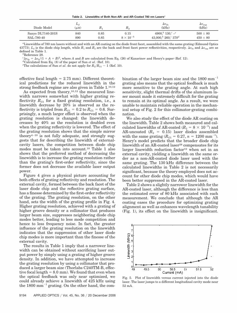
Fig. 5. Plot of linewidth versus current injected into the diodelaser. The laser jumps to a different longitudinal cavity mode near52 mA.
Table 2. Linewidths of Both Non-AR- and AR-Coated 780 nm Lasersa
Diode ModelLd
(�M) R1 R2
��th
(kHz)��exp
(kHz)
Sanyo DL7140-201S 840 0.85 0.15 4900,b 130,c –e 500 � 80SAL-780-40 890 0.85 8 � 10�5 43,000,b 260,c 370d 450 � 80
aLinewidths of 780 nm lasers without and with an AR coating on the diode front facet, assembled with the same grating (Edmund Optics43773). Ld is the diode chip length, while R1 and R2 are the back and front facet power reflectivities, respectively. ��th and ��exp are asdefined in Table 1.
bReference 28.c��th � ��0�(1 A B)2, where A and B are calculated from Eq. (26) of Kazarinov and Henry’s paper (Ref. 12).dCalculated from Eq. (8) of the paper of Sun et al. (Ref. 10).eThe calculations of Sun et al. do not apply for R2�RG1 � 1 (Ref. 10).
9194 APPLIED OPTICS � Vol. 45, No. 36 � 20 December 2006

This result also agrees with the findings of Binderet al., i.e., lasers with different front facet reflectivi-ties exhibit similar linewidths as long as they are insingle-mode operation.17
The linewidth error of 80 kHz is estimated from thefact that the amount of current injected into the diodelaser influences the extent to which the laser operatesin a single mode, which in turn affects the linewidth(Fig. 5). When the laser is about to jump to a differentmode, it becomes slightly multi-mode, and the line-width increases by an order of magnitude due tomode competition. Although we have verified that thelaser operated in a single mode during our frequencynoise measurements, Fig. 5 shows that there is still acurrent-dependent linewidth variation of �80 kHz or20% in the single-mode regime.
Table 3 summarizes the smallest linewidths mea-sured for the near-IR diode lasers (780, 852 nm).For comparison, the linewidth of the near-UV laser�399 nm� is included.
4. Mechanical Stability of Laser Mounts
Figure 6 shows a new laser mount (mount B) that isdesigned to reduce mechanical oscillations at higheracoustic frequencies. For the regular mount (mountA, see Fig. 2),2 the grating and laser diode are sepa-rately attached to a third aluminum piece that servesas the base of the mount. The vertical and horizontalgrating angles are adjusted by turning the screws ofthe mirror mount holding the grating. Conversely, formount B, the aluminum block containing the gratingis attached directly to the block containing the laserdiode via four nylon pull screws. Three stainless steelscrews, which push on the block containing the grat-
ing and a piezostack sandwiched between the twoblocks, respectively, allow the vertical and horizontalgrating angles to be adjusted. In fact, the verticalangle only needs to be adjusted slightly, because theoptical feedback is already near optimal when thegrating sits flush in the machined pocket. Mount Balso includes a mirror, which couples the beam out ofthe mount in a fixed direction regardless of the grat-ing’s horizontal angle.30
The mechanical properties of mount B are charac-terized in terms of its frequency noise power spectraldensity and rms jitter at low Fourier frequencies (upto 5 kHz) and are plotted in Figs. 7 and 8, respec-tively. For comparison, Figs. 7 and 8 also display thedata for a laser assembled with mount A. At firstglance, mount A appears to be more stable than
Table 3. Best Achieved Linewidthsa
Atoms�
(nm)AR
Coatingn
(mm�1) ���� RG1
��exp
(kHz)
Cs 852 Yes 1800 8400 0.16 320 � 60Rb 780 Yes 1200 4100 0.27 450 � 80Yb 399 No 2400 8200 0.60 2508 � 70
aNarrowest linewidths achieved with 852 and 780 nm lasers andtheir corresponding diode and grating parameters as defined inTable 1.
Fig. 6. (Color online) Schematic of mount B. The four nylon pullscrews that attach the two aluminum blocks to each other are notdrawn.
Fig. 7. (Color online) Frequency noise power spectral densities formount B (open circles) and mount A (filled triangles) lasers. MountB only has a strong mechanical resonance at 500 Hz, whereasmount A has mechanical resonances at 2 kHz.
Fig. 8. (Color online) Rms jitters of lasers assembled both withmount B (open circles for unlocked and solid curve for locked) andmount A (filled triangles for unlocked and dashed curve for locked)versus integration bandwidth f. The rms jitter is given by��jitter�f � � �0
f �S�f ���2df ��1�2.
20 December 2006 � Vol. 45, No. 36 � APPLIED OPTICS 9195
mount B, because its overall noise is lower. However,the low-frequency noise can be easily reduced with afeedback circuit. In fact, the lower the frequencies atwhich mechanical resonances occur, the easier it isfor the feedback circuit to compensate for noise. Inthis respect, mount B is better than mount A becauseits strong mechanical resonance only occurs at 500Hz, whereas mount A has strong resonances at �2kHz. As shown in Fig. 8, the rms jitter of the laserbuilt with mount B is much lower than that for mountA, when both lasers are locked. Integrating from 0 Hzup to a bandwidth of f � 10 kHz, we achieve rmsjitters of ��jitter�f � � 0
f �S�f ���2df ��1�2 � 40 and 100kHz for the actively stabilized lasers built withmounts B and A, respectively.
5. Conclusion
We have measured frequency noise power spectraldensities to determine laser linewidths for variousgrating laser setups. We find typical linewidths of250–600 kHz for lasers operating near 399, 780, and852 nm. The linewidth depends on the type of gratingand collimator. The presence of an AR coating has aninsignificant effect on the linewidth reduction butenhances tuning stability. On the other hand, thehigher the grating reflectivity and grating resolution,the narrower the linewidth. In particular, the gratingresolution has a larger effect on the linewidth thanthe grating reflectivity, indicating that a completetheory of external-cavity diode lasers has to accountfor line broadening due to mode competition.
Using a new laser mount with improved mechani-cal properties, we were able to achieve a rms jitter of40 kHz for an actively stabilized system with a loopbandwidth of only 1.5 kHz.
We gratefully acknowledge support from the Na-tional Science Foundation, Defense Advanced Re-search Projects Agency, and the U.S. Army ResearchOffice. H. Loh thanks the John Reed UndergraduateResearch Opportunities Program Fund, Josephine deKármán Fellowship, and Agency for Science, Technol-ogy and Research (Singapore) Scholarship. J. Simon issupported by the U.S. Department of Defense throughthe National Defense Science and Engineering Grad-uate Fellowship.
References1. C. E. Wieman and L. Hollberg, “Using diode lasers for atomic
physics,” Rev. Sci. Instrum. 62, 1–20 (1991).2. L. Ricci, M. Weidemüller, T. Esslinger, A. Hemmerich, C. Zim-
mermann, V. Vuletic, W. König, and T. W. Hänsch, “A compactgrating-stabilized diode laser system for atomic physics,” Opt.Commun. 117, 541–549 (1995).
3. H. Patrick and C. E. Wieman, “Frequency stabilization of adiode laser using simultaneous optical feedback from a diffrac-tion grating and a narrowband Fabry–Perot cavity,” Rev. Sci.Instrum. 62, 2593–2595 (1991).
4. R. Lang and K. Kobayashi, “External optical feedback effectson semiconductor injection laser properties,” IEEE J. Quan-tum Electron. 16, 347–355 (1980).
5. S. Saito, O. Nilsson, and Y. Yamamoto, “Oscillation centerfrequency tuning, quantum FM noise, and direct frequency
modulation characteristics in external grating loaded semicon-ductor lasers,” IEEE J. Quantum Electron. 18, 961–970 (1982).
6. E. Patzak, H. Olesen, A. Sugimura, S. Saito, and T. Mukai,“Spectral linewidth reduction in semiconductor lasers by anexternal cavity with weak optical feedback,” Electron. Lett. 19,938–940 (1983).
7. E. Patzak, A. Sugimura, S. Saito, T. Mukai, and H. Olesen,“Semiconductor laser linewidth in optical feedback configura-tions,” Electron. Lett. 19, 1026–1027 (1983).
8. G. P. Agrawal, “Line narrowing in a single-mode injection laserdue to external optical feedback,” IEEE J. Quantum Electron.20, 468–471 (1984).
9. C. H. Henry, “Theory of spontaneous emission noise in openresonators and its application to lasers and optical amplifiers,”J. Lightwave Technol. 4, 288–297 (1986).
10. H. Sun, S. Menhart, and A. Adams, “Calculation of spectrallinewidth reduction of external-cavity strong-feedback semi-conductor lasers,” Appl. Opt. 33, 4771–4775 (1994).
11. K. Kikuchi and T. Okoshi, “Simple formula giving spectrum-narrowing ratio of semiconductor-laser output obtained byoptical feedback,” Electron. Lett. 18, 10–11 (1982).
12. R. F. Kazarinov and C. H. Henry, “The relation of line nar-rowing and chirp reduction resulting from the coupling of asemiconductor laser to a passive resonator,” IEEE J. QuantumElectron. 23, 1401–1409 (1987).
13. B. Tromborg, H. Olesen, X. Pan, and S. Saito, “Transmissionline description of optical feedback and injection locking forFabry–Perot and DFB lasers,” IEEE J. Quantum Electron. 23,1875–1889 (1987).
14. M. W. Fleming and A. Mooradian, “Spectral characteristicsof external-cavity controlled semiconductor lasers,” IEEE J.Quantum Electron. 17, 44–59 (1981).
15. R. Wyatt and W. J. Devlin, “10 kHz linewidth 1.5 �m InGaAsPexternal cavity laser with 55 nm tuning range,” Electron. Lett.19, 110–112 (1983).
16. R. Wyatt, “Spectral linewidth of external cavity semiconductorlasers with strong, frequency-selective feedback,” Electron.Lett. 21, 658–659 (1985).
17. J. O. Binder, G. D. Cormack, and A. Somani, “Intermodaltuning characteristics of an InGaAsP laser with optical feed-back from an external-grating reflector,” IEEE J. QuantumElectron. 26, 1191–1199 (1990).
18. G. Genty, A. Gröhn, H. Talvitie, M. Kaivola, and H. Ludvigsen,“Analysis of the linewidth of a grating-feedback GaAlAs laser,”IEEE J. Quantum Electron. 36, 1193–1198 (2000).
19. G. Genty, M. Kaivola, and H. Ludvigsen, “Measurements oflinewidth variations within external-cavity modes of a grating-cavity laser,” Opt. Commun. 203, 295–300 (2002).
20. I. D. Henning, “Linewidth broadening in semiconductor lasersdue to mode competition noise,” Electron. Lett. 19, 935–936(1983).
21. H. Talvitie, A. Pietiläinen, H. Ludvigsen, and E. Ikonen,“Passive frequency and intensity stabilization of extended-cavity diode lasers,” Rev. Sci. Instrum. 68, 1–7 (1997).
22. C. Audoin, “Frequency metrology,” in Metrology and Funda-mental Constants, corso 68 of International School of PhysicsEnrico Fermi, A. F. Milone, P. Giacomo, and F. Leschiutta, eds.(North-Holland, 1980), pp. 169–222.
23. H. Li and H. R. Telle, “Efficient frequency noise reduction ofGaAlAs semiconductor lasers by optical feedback from an ex-ternal high-finesse resonator,” IEEE J. Quantum Electron. 25,257–264 (1989).
24. T. Laurila, T. Joutsenoja, R. Hernberg, and M. Kuittinen,“Tunable external-cavity diode laser at 650 nm based on a trans-mission diffraction grating,” Appl. Opt. 41, 5632–5637 (2002).
25. T. Kiguchi, A. Uematsu, M. Kitano, and H. Ogura, “Gratingexternal cavity diode lasers with broad tunable range and
9196 APPLIED OPTICS � Vol. 45, No. 36 � 20 December 2006

narrow spectral linewidth for high-resolution spectroscopy,”Jpn. J. Appl. Phys., Part 1 35, 5890–5895 (1996).
26. K. L. Corwin, Z.-T. Lu, C. F. Hand, R. J. Epstein, andC. E. Wieman, “Frequency-stabilized diode laser with theZeeman shift in an atomic vapor,” Appl. Opt. 37, 3295–3298(1998).
27. B. Dahmani, L. Hollberg, and R. Drullinger, “Frequency sta-bilization of semiconductor lasers by resonant optical feed-back,” Opt. Lett. 12, 876–878 (1987).
28. C. H. Henry, “Theory of the linewidth of semiconductor lasers,”IEEE J. Quantum Electron. 18, 259–264 (1982).
29. M. W. Fleming and A. Mooradian, “Fundamental line broad-ening of single-mode (GaAl) As diode lasers,” Appl. Phys. Lett.38, 511–513 (1981).
30. C. J. Hawthorn, K. P. Weber, and R. E. Scholten, “Littrow’configuration tunable external cavity diode laser with fixeddirection output beam,” Rev. Sci. Instrum. 72, 4477–4479(2001).
20 December 2006 � Vol. 45, No. 36 � APPLIED OPTICS 9197