industrial steam trapping handbook - infohouseinfohouse.p2ric.org/ref/28/27531.pdf · industrial...
TRANSCRIPT

INDUSTRIAL STEAM TRAPPING
HANDBOOK
4-
f


INDUSTRIAL STEAM TRAPPING
HANDBOOK
3rd Edition 0 Copyright 1984
Yarway Corporation Blue Bell, PA 19422, U.S.A.
bY
Reproduction of all or in part without express permission of copyright owner is strictly prohibited
Price $9.95

INDUSTRIAL STEAM TRAPPING HANDBOOK
Chapter 1
Chapter 2
Chapter 3
Chapter 4
Chapter 5
Chapter 6
Chapter 7
Appendix “A”
Appendix “B”
Appendix “C”
Appendix “D”
CONTENTS Page
Steam Trapping, An Overview ..................... 1 The steam trapping industry. Users & manufacturers of steam traps. Why steam traps are necessary, where they are used, and the need to clarify and simplify the basics for those with an interest in steam traps. Basics of Steam & Steam Systems ................... The steamkondensate cycle. Definitions of terms. Basic principles associated with steam traps.
The various operating principles of steam traps, the advantages and disadvantages of each type. The volun- tary standards associations giving guidance to the industry.
The trap application universe, the selection process, and fundamental selection criteria. The trap sizing process and the basic steps in detail.
The essentials for good trap performance. Strainers, air vents, vacuum breakers, check valves, test tees, return systems. Group trapping.
Maintenance programs and the essentials for success. Steam trapping standards. Trap checking techniques and the trap checking decision tree. Condensate Return Systems ...................... 69 The major elements of such systems: considerations in the sizing and selection of steam traps for the system: problems resulting from undersized returns.
5
Operating Principles of Steam Raps ................ 13
Principles of Steam Trap Application ............... 29
Principles of Steam Rap Installation ............... 47
Steam Rap Maintenance & Rouble Shooting ........ 55
APPENDIX
“How t o . . ........................................ 81 Notes on how to trap process equipment of several types. How to trap steam mains and steam tracers. How to estimate steam main condensate loads. Steam Trap Evaluation Methods .................... Describes various criteria for trap evahation; empha- sizes calorimeter technique for determination of heat loss and other test procedures employed by Yarway.
99
Glossary of Terms ................................. 108
Useful Tables ..................................... 111


CHAPTER 1
STEAM TRAPPING OVERVIEW
Introduction Steam traps are used wherever steam is used. They are automatic valves. Their basic function is to allow condensate to flow, while preventing the passage of steam until it has given up its heat by condensing back to water. There are literally millions of steam traps in use worldwide.
Steam trap users range from laundries and tailor shops (with a few traps) to huge refineries and chemicak complexes (with 10,000 to 15,000 units). Paper mills, textile plants, steel mills and food processors are all large users of steam and steam traps. Colleges, hospitals, prisons, government agencies, and similar large building com- plexes with central steam heating systems are also users of steam traps. This wide range of users creates an equally wide range of steam trap applications. In turn this wide variety of applications is matched by a seemingly bewildering array of steam trap types and sizes.
Energy Costs Lead to New Awareness In recent years, user interest in steam traps
has closely paralleled the increases in energy costs. This interest has been born of necessity. The high fuel costs associated with malfunctioning traps, and the low level of attention generally paid to their proper use, have simply become eco- nomically too painful to ignore.
A few of the larger and more sophisti- cated trap users have developed test and evaluation programs to determine the kinds of traps that perform best in their plants. They have experimented with vari- ous types from different domestic manu- facturers and, for the first time, have begun to look seriously at the offerings of interna- tional suppliers. Organizational changes have created the job of Energy Conserva- tion Officer, and his function invariably has led him to study the subject of steam traps. As a result, the skills necessary for diagnosing inefficient steam systems, and prescribing appropriate cures , have improved. Figure# 1-1shows an ultrasonic steam leak detector and an infrared heat loss sensor. Both are used increasingly in efforts to detect energy losses. Identifying
Figure #I-I Ultrasonic steam leak detector and infrared heat loss sensor
1
malfunctioning and misapplied steam traps is now recognized not only as an important task, but also one of greater com- plexity than initially perceived. Services of consultants and service companies spe- cializing in the proper maintenance of steam traps have become increasingly popular.
No Universal Steam ’hap With all of this attention and inquiry, many users have become aware that there is no universal trap or single trapping technol- ogy for all their needs. Appreciation has developed for the fact that many criteria must be considered in selecting a steam trap for a particular application. Different trap types will be selected or preferred according to the importance a user assigns to various criteria.
The objective of this book is to provide an up-to-date reference for trap users whose requirements may range widely. Its intent is to clarify and simplify the basics relating to steam trap selection, sizing, installation and maintenance without ignoring the subtleties and nuances of interest to the more knowledgeable reader.
Steam
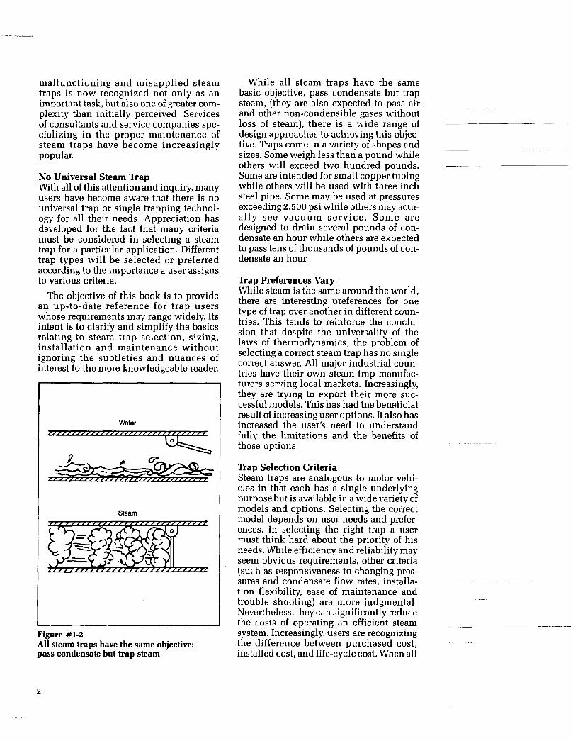
Figure #1-2 All steam traps have the same objective: pass condensate but trap steam
While all steam traps have the same basic objective, pass condensate but trap
and other non-condensible gases without loss of steam), there is a wide range of design approaches to achieving this objec- tive. Traps come in a variety of shapes and sizes. Some weigh less than a pound while others will exceed two hundred pounds. Some are intended for small copper tubing while others will be used with three inch steel pipe. Some may be used at pressures exceeding 2,500 psi while others may actu- ally see vacuum serv ice . Some are designed to drain several pounds of con- densate an hour while others are expected to pass tens of thousands of pounds of con- densate an hour.
steam, (they are also expected to pass air ~- ~
’hap Preferences Vary While steam is the same around the world, there are interesting preferences for one type of trap over another in different coun- tries. This tends to reinforce the conclu- sion that despite the universality of the laws of thermodynamics, the problem of selecting a correct steam trap has no single correct answer. All major industrial coun- tries have their own steam trap manufac- turers serving local markets. Increasingly, they are trying to export their more suc- cessful models. This has had the beneficial result of increasing user options. It also has increased the user’s need to understand fully the limitations and the benefits of those options.
n a p Selection Criteria Steam traps are analogous to motor vehi- cles in that each has a single underlying purpose but is available in a wide variety of models and options. Selecting the correct model depends on user needs and prefer- ences. In selecting the right trap a user must think hard about the priority of his needs. While efficiency and reliability may seem obvious requirements, other criteria (such as responsiveness to changing pres- sures and condensate flow rates, installa- tion flexibility, ease of maintenance and trouble shooting) are more judgmental. Nevertheless, they can significantly reduce
system. Increasingly, users are recognizing the difference between purchased cost, installed cost, and life-cycle cost. When all
~ ~~ -~~ ~~~ the costs of operating an efficient steam -
of these issues are considered, steam trap selection becomes a matter requiring thoughtful evaluation. At the least, a wrong selection means a savings opportunity missed;-at the worst, it can mean a costly disruption of production.
Cost Considerations Steam traps, like all other pieces of mechanical equipment, will fail in time. They may fail closed thereby restricting flow, or they may fail open, freely passing steam. It is difficult to appreciate fully the cost consequences of malfunctioning steam traps in a large plant without going through some basic arithmetic. Consider a plant with 6000 traps and a reasonably good maintenance program. Experience allows the conservative assumption that at least 10% have failed in the open position and are “blowing through”, wasting steam. Six hundred traps, losing 20 pounds of steam per hour per unit, for twenty-four hours, are losing 288 thousand pounds of steam per day. While steam generating costs vary from plant to plant (and are revised annually) an estimate of $5.00 per thousand pounds is very conservative. In this example, that equals $1,440 per day for a rate of $525,600 per year! 6,000 traps x 10% = 600 failed traps
$1,44Olday x 365 daylyear = $525,60O/year
These are all conservative numbers! Nor is it necessary to have several thou-
sand traps to have the potential for very large steam and dollar losses. Several failed large capacity traps can also be the source of costly steam losses.
The costs resulting from traps that have failed in the closed position are not consid- ered in the preceding example. They are much more difficult to quantify but they are no less real. These costs result from reduced productivity or product quality and higher rates of equipment damage due to corrosion, water hammer or freeze ups.
Why would any plant manager allow his steam traps to waste this amount of steam?
The answer is that he probably doesn’t really know it is happening. If each failed trap had high visibility, it would be a differ- ent story. But with traps discharging into a closed return system the same telltale plumes of vapor, that quickly identify the leaking valve packing or flanged joint, are missing. Because frequently they fail to create a clearly visible problem, traps s imply don’t receive t h e a t ten t ion they deserve.
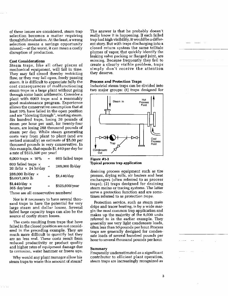
Process and Protection ’haps Industrial steam traps can be divided into two major groups: (1) traps designed for
Cool Process Fluid
Figure #1-3 Qpical process trap application
draining process equipment such as tire presses, drying rolls, air heaters and heat exchangers (often referred to as process traps); (2 ) traps designed for draining steam mains or tracing systems. The latter serve a protection function and are some- times referred to as protection traps.
Protection service, such as steam main drips and tracer heating, is by a wide mar- gin the most common trap application and makes up the majority of the 6,000 units referred to in the earlier example. They generally see very light condensate loads, often less than 50 pounds per hour. Process traps are generally designed for conden- sate loads of several hundred pounds per hour to several thousand pounds per hour.
Summary Frequently underestimated as a significant contributor to efficient plant operation, steam traps are increasingly recognized as
3

1
Steam from Boiler P
J I Turbo Generator
Figure #I-4 Drip traps protect equipment and piping against damage that can result if condensate is not drained
a small piece of equipment with a large role in optimizing plant efficiency.
Designed to release condensate and air from steam systems without allowing the passage of steam, they are a small auto- matic self-actuated valve. They come in a wide range of sizes and models because they must meet a wide range of pressures and condensate load conditions. Users also tend to have different preferences for the kind of performance they expect from a trap.
Steam traps that have failed in service are seldom highly visible unless they are discharging directly to the atmosphere. Because of this, they generally receive
inadequate ma in tenance a t ten t ion . The direct cost consequences of this inattention, when measured in terms of unnecessary fuel consumption, can be startlingly high.
The indirect cost consequences, in terms of lost production or damaged equipment, can also be significant although they are less easily quantified and frequently not properly assigned to a faulty steam trap installation. Any successful effort to con- trol these costs must be based on a solid foundation of certain basic factual infor- mation about steam, condensate, how steam traps work, and the requirements of the systems into which they are installed.
4

CHAPTER 2 ~~ ~ ~~ ~~~ ~ ~~
BASICS OF STEAM AND STEAM SYSTEMS
Introduction Generating steam is not an end in itself. Steam is generated as a convenient way of transferring energy (heat and pressure) from one place to another. Its uses can be for heating, drying, cooking, curing or spinning a turbine-to name a few. It is the special properties of steam and water, and their easy availability, that make them so widely selected for this energy transferring role.
A review of some fundamentals con- cerning steam and condensate can be helpful. When water is heated, its temper- ature continues to rise up to the boiling point. Continued heating does not raise the temperature of the water but causes it to boil into steam having the same tempera- ture as the liquid.
If water is heated in a closed vessel, the reaction is different in an important way.
Once boiling starts and with the heating continued, several things occur; the pres- sure in the vessel increases and the temper- ature of both the water and the steam also increases. This means that water has a new and higher boiling point as pressures increase. For instance, at 100 psi water boils at 338F instead of the familiar 212F at atmospheric pressure. If heating continues after all the water has been evaporated, the temperature and pressure of the steam con- tinues to increase and the steam is then called superheated steam.
If the heating is discontinued, a process is started that is just the reverse of that described above. As the vessel cools, the pressure also decreases. Initially, no con- densation takes place as the steam gives up that portion of the heat it acquired after all the water in the vessel evaporated. After all
t High Pressure Steam
Steam Main n n r - Air
1 Trap
Boiler
Flash Tank
Jacketed Kettle
End of Main lTrap
x Figure #2-1 Steam and Condensate System
5

Total Heat of Steam
(1150 BTU)
1 pound water evaporated into steam at atmos- pheric pressure
- Latent
vaporization
Sensible heat of water
--
Heat required to convert 1 pound of water at 21 2F to 1 pound of steam at 212F
Heat required to raise 1 pound of water from 32F to 212F
970 BTU
180 BTU
Figure #2-2 Total heat of steam at atmospheric pressure
the superheat has been given up, however, water starts to condense on the vessel walls. Continued cooling results in a decreasing pressure and the formation of more condensate. Ultimately all the steam will condense into water and the tempera- ture and pressure will return to that which existed before the heating process started.
A more realistic situation is that of a steam generator or boiler with its heat and pressure energy being transferred by a pip- ing system to equipment that is performing a useful task. As the steam gives up its heat in the equipment, condensate is formed. The condensate can then return to the boiler for reheating and the cycle is repeated. Figure #2-1 shows such a system.
Basic Definitions Some basic definitions are really essential to a full understanding of the steam gener- ating cycle and the proper use of steam traps in an efficient steam-using system:
0 British thermal unit (BTU): the quantity of heat required to raise one pound of water 1 degree Fahrenheit. 0 Sensible heat: heat that produces a tem- perature rise in a body such as water. 0 Latent heat of vaporization: heat that produces a change of state without a change in temperature, such as changing water into steam. 0 Saturated steam or dry saturated steam: steam at the temperature of the water from which it was evaporated. 0 Wet steam: typically, steam is not dry
6
but contains fine water droplets resulting from the boiling process. The significance is that wet steam has a lower heat content than dry saturated steam. 0 Saturated water: water at the same tem- perature as the steam with which it is in contact. 0 Superheat: heat added to dry saturated steam. Additional Concepts 0 Total heat of steam: the total BTU con- tent of steam, including sensible heat of water, latent heat of vaporization and superheat (if any). This concept is shown in Figure #2-2 for steam at atmospheric pressure. The conclusion that can be drawn from Figure #2-2 is that there is more than five times the heat in one pound of steam at 212F than in one pound of water at the same temperature. This means that for effi- cient heating with steam, condensate must be removed quickly. The presence of con- densate acts to reduce the surface area exposed to steam with its much greater BTU (heat) content. The total heat of saturated steam at any pressure is the sum of latent and sensible heat and is shown in Figure #2-3.
Higher pressures mean higher tempera- tures and faster heat transfer. But it is worth noting that higher pressures mean less latent heat of steam. More steam must be condensed at higher pressures, to transfer a given number of BTU’s, than is the case at lower pressures.

Total heat of steam (L&S)
Latent heat (L) available at various pressures
Sensible heat (S) available at various pressures
Sensible heat at atmospheric
10 20 30 40 50 60 70 80 90 100
Figure #2-3 Total heat of steam at pressures of 0 to 100 psi
500
Area of superheated steam.
LL Boiling point of water - 400 '
3 steam and saturated water g at various pressures)
I (temperature of saturated @
Q
300
Area of subcooled water or condensate
~~ 200
0 The saturation curve: graphic represen- tation of the pressure and temperature at which saturated steam and water exist. As pressures increase in a boiler, so does the boiling point of water. Figure #2-4 shows how the boiling point increases from 212F at 0 psi to 489F at 600 psi. This curve is called the Saturation Curve. At temperatures above the curve, steam is in a suDerheated condition. At temDeratures
are in the saturated condition. At tempera- tures below the curve, condensate is in the subcooled condition; i.e. its temperature is below that of saturated steam and water at that pressure.
0 Discharge temperature of steam traps: The temperature of discharging conden- sate measured at the steam trap's inlet. Also, sometimes referred to as the tempera-
7

500
400
300 ?2 E
E
3
(u P
- 2 200
1 Saturation Curve I (Boiling at Various Point Pressures] of Water
\ I A*/@/ /=== -I /-*’
/- .-
Trap B Discharge temperature of a steam trap that is unable to parallel the saturation curve. Note that in this example, this trap will be unable to close at pressures below 25 psi
loo 0 m 100 200 300 400 500 600
Pressure, psi
Figure #2-5 Discharge temperature characteristics of two different types of steam traps
Understanding the physical phenomena represented by the saturation curve is ess- tential to understanding why in certain applications some types of steam traps are preferred over others. Most steam traps are unable to perform well over the entire range of pressure and temperature condi- tions represented in Figure #2-4. For example, some traps will work well at higher pressures but will be unable to shut off the flow of steam at lower pressures. Alternatively, some that shut off steam at lower pressures are unable to open suffi- ciently to allow a full flow of condensate at higher pressures. Also, many applications require a steam trap that will discharge condensate very quickly after it forms to obtain maximum heating efficiency for the equipment it is serving. This condensate will be very close to steam temperature- perhaps only 3 or 4 degrees below that of steam. In other applications, the heat in the condensate as well as the heat in the steam can be used. In these cases the steam trap is
not expected to open until the condensate is 30 or 40 degrees below that of steam.
Steam traps that open and close at tem- peratures just a few degrees below steam temperature are often referred to as “hot” traps. Those that discharge condensate sig- nificantly sub-cooled below steam tem- perature are called “cool” traps, even though they may be operating at tempera- tures much higher than 212F. The require- ments of the application determine which type of trap is most suitable.
Figure #2-5 shows graphically the con- cepts described above. One type of trap (represented by the Trap A curve) opens quickly to discharge condensate when its temperature has dropped only a few degrees below that of steam. Its discharge temperature is said to parallel the satura- tion curve because it opens to discharge condensate the same few degrees below steam temperature over a wide range of steam pressures.
~
8

0 25 50
100 200 300 400 600
Heat in BTU’s per lb
212 267 298 338 388 422 448 489
Sensible
180 236 267 309 362 399 428 475
In contrast, the number of degrees that condensate must cool below steam tem- perature before a different type of trap (rep- resented by the Trap B curve) will open, varies significantly at different pressures. In this example condensate must cool a relatively large number of degrees below that of steam before it will open at pres- sures above 300 psi. As steam pressures drop below 300 psi, the number of degrees condensate must cool before the trap will open is progressively reduced until at 25 psi the trap is open continuously (unable to close), discharging both steam and condensate. 0 Steam tables: listings of the heat content of steam in BTU’s and its volume in ftVlb at various pressures and temperatures. The properties of saturated steam are most frequently summarized in Steam Tables, some of which are very extensive. Figure #2-6 shows this form in a very abbreviated listing. Appendix D, page 103 provides more complete but still abbreviated tables.
Steam tables are essential for calculating the amount of steam to do a certain heating job. When the amount of steam required is known, so is the amount of condensate that will be produced and, in turn, the size of steam trap that is required. Chapter 4, Steam Trap Application, discusses in greater detail the calculations necessary in estimating condensate loads. 0 Flash steam: steam that results when saturated water or condensate is dis-
Latent
970 934 912 881 837 805 776 728
Total
1150 1170 1179 1190 1199 1204 1204 1203
Specific Volume of Saturated ~ ~ ~~ ~ ~~
Vapor, - f t 3 m
~~ ~~~
27 10.5 6.7 3.9 2.1 1.5 1.1 0.75
charged to a lower pressure. When satu- rated water or condensate is released to a lower pressure, its boiling point is instan- taneously reduced. Some of the conden- sate will boil or flash into steam. This is steam that could not exist at the higher pressure.
While the brief explanation of flash steam given above is accurate, the signifi- cance of the subject for both steam systems and steam trapping justifies more discus- sion. There are several practical reasons for this: I. The individual that expects to know the difference between a trap that is operating properly and one that is not must know the difference between flash steam and live steam. 2. Flash steam created unexpectedly in a poorly planned steam system can signifi- cantly reduce the efficiency of that system. It can also (under extreme conditions) cause malfunction of certain types of steam traps. 3. Flash steam in a properly designed steam system is an important element in using steam efficiently at successively reduced pressures for a series of different jobs.
By way of example, consider a steam trap draining a piece of equipment operating at 100 psi. Steam flows to the equipment and condenses as it gives up its heat. It is then that the steam trap should open, to drain the condensate, and reclose before live
9

steam escapes. But the temperature of con- densate at 100 psi is 338F and, if it drains directly to atmospheric pressure, the laws of thermodynamics require it to achieve its atmospheric boiling point instantly and become 212F. This is accomplished by some of the condensate flashing into steam also at 212F. This discharge from the outlet of the trap then is a combination of hot condensate and flash steam and is typical of a properly functioning steam trap.
Confusion over flash steam starts with an individual, who is looking at a trap that is discharging to atmosphere, and who then attempts to decide if the steam com- ing from that trap is really live steam that has leaked through (a faulty trap) or if it is flash steam, the normal result of hot con- densate boiling upon release to a lower pressure (a healthy trap). Both experience and judgment are needed to make a correct assessment. Chapter # 6, Steam Trap
Flash steam problems
8.7 10.2 11.6 12.8
13.8 15.0 16.7 18.4
20.0 21.2 22.6 23.7 25.0
Maintenance and Trouble-Shooting, dis- cusses this problem more fully.
piping systems used to return condensate
that have not been properly designed to accept the volume of flash steam they actu- ally experience will perform poorly. Flash steam expands to many times the volume that it had as water. Saturated water at 15 psi will have about 1600 times the volume when it flashes to steam at atmospheric pressure. This expansion process can so pressurize condensate return systems that proper drainage of the steam heated equip- ment, and performance of certain types of steam traps, are impaired. Connecting additional equipment to an already exist- ing condensate return system is frequently the cause of excessive backpressures.
~
Flash steam can create problems in the
to the boiler. Condensate return systems
~ ~~
_ _
~~
7.4 8.8
10.0 11.5
12.4 13.6 15.5 17.0
18.7 20.0 21.4 22.6 23.6
Flash steam as a valuable resource Flash steam in a properly designed cascad-
Initial steam press., psig.
25 50 75
125 150 175 200
225 250 300 350
400 450 500 550 600
Sat. temp.
F.
267 298 320
353 366 377 388
397 406 422 436
448 459 470 480 489
0
5.7 9.0
11.3
-
14.8 16.8 17.4 18.7
19.7 20.7 22.4 24.0
-
25.5 26.8 28.2 29.2 30.2
5
4.1 7.4
10.8
-
13.4 14.8 16.0 17.5
18.2 19.2 21.0 22.7
-
24.2 25.3 26.7 27.8 28.8
10
3.0 6.2 8.6
-
12.2 13.7 15.0 16.2
17.0 18.2 20.0 21.6
-
23.0 24.4 25.7 27.0 28.0
Flash-tank pressure", psig.
20
1 .o 4.3 6.7
-
10.3 11.8 13.0 14.4
15.4 16.4 18.2 20.0
-
21.5 22.7 24.0 25.3 26.4
50 -
0 0
2.5 4.6
6.3 7.8 9.0
10.4
11.4 12.5 14.4 16.0
17.7 19.0 20.4 21.6 22.7
-
-
-
75 -
0 0 0
2.2
3.8 5.4 6.7 8.0
9.0 10.0 11.0 13.8
-
-
15.6 16.8 18.2 19.5 20.5
100
0 0 0 0
1.7 2.3 4.6 6.0
7.0 8.2
10.0 12.0
-
-
-
13.5 15.0 16.4 17.5 18.7
125
0 0 0 0
0 1.6 3.0 4.4
5.4 6.6 8.5
10.4
-
-
-
12.0 13.4 14.6 16.0 17.3
150
0 0 0 0
0 0
1.5 2.8
3.8 5.0 7.0 8.9
-
-
-
10.5 12.0 13.4 14.7 16.0
*The vessel used to receive high pressure condensate, and flash steam which can be used at lower pressures for additional heating, is called a flash tank.
Figure #2-7 Percent of Flash Steam Formed
10
ing return system allows for the efficient use of steam doing several different heating tasks at successively reduced steam pres- sures. Table (Figure #2-7) shows the per- cent of flash steam formed when conden- sate is discharged from a higher to lower pressure. For example, 7% of condensate discharged from a 100 psi system to a 30 psi system will be converted to flash steam. Tables such as these are used in designing condensate return tanks and systems.
Factors Affecting Steam Systems Up to this point emphasis has been
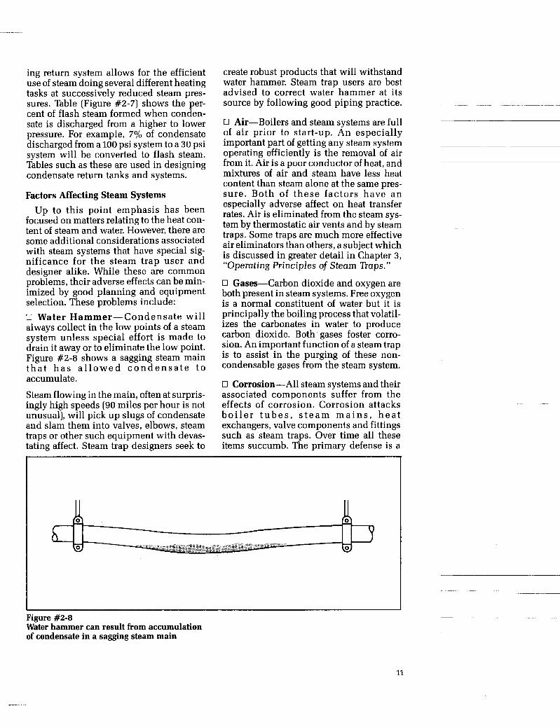
focused on matters relating to the heat con- tent of steam and water. However, there are some additional considerations associated with steam systems that have special sig- nificance for the steam trap user and designer alike. While these are common problems, their adverse effects can be min- imized by good planning and equipment selection. These problems include: 0 Water Hammer-Condensate wil l always collect in the low points of a steam system unless special effort is made to drain it away or to eliminate the low point. Figure #2-8 shows a sagging steam main t h a t h a s a l l o w e d c o n d e n s a t e t o accumulate.
Steam flowing in the main, often at surpris- ingly high speeds (90 miles per hour is not unusual), will pick up slugs of condensate and slam them into valves, elbows, steam traps or other such equipment with devas- tating affect. Steam trap designers seek to
create robust products that will withstand water hammer. Steam trap users are best advised to correct water hammer at its source by following good piping practice.
0 Air-Boilers and steam systems are full of air prior to start-up. An especially
operating efficiently is the removal of air from it. Air is a poor conductor of heat, and mixtures of air and steam have less heat content than steam alone at the same pres- sure. Both of these factors have a n especially adverse affect on heat transfer rates. Air is eliminated from the steam sys- tem by thermostatic air vents and by steam traps. Some traps are much more effective air eliminators than others, a subject which is discussed in greater detail in Chapter 3, “Operating Principles of Steam Traps.”
0 Gases-Carbon dioxide and oxygen are both present in steam systems. Free oxygen is a normal constituent of water but it is principally the boiling process that volatil- izes the carbonates in water to produce carbon dioxide. Both gases foster corro- sion. An important function of a steam trap is to assist in the purging of these non- condensable gases from the steam system.
0 Corrosion-All steam systems and their associated components suffer from the effects of corrosion. Corrosion attacks b o i l e r t u b e s , s t e a m m a i n s , h e a t exchangers, valve components and fittings such as steam traps. Over time all these items succumb. The primary defense is a
-~
important part of getting any steam system ~ ~~
Figure #2-a Water hammer can result from accumulation of condensate in a sagging steam main
13

carefully monitored and maintained boiler feedwater treatment system that controls the gases (oxygen and carbon dioxide) which promote corrosion. Carbon dioxide by itself is not corrosive, but it can combine with free hydrogen to form carbonic acid which is corrosive. A principal reason stainless steel is used extensively in steam traps is to resist the effect of corrosion and prolong the life of the trap.
0 Dirt-The trash and accumulated debris in a newly piped steam system must be seen to be believed. In older systems dirt, corrosion products, and sealants from the maintenance repair of a leaky joint, continue to plague such components as small valves, instruments and steam traps. These devices with their small clearances and vulnerable seat ing surfaces are especially susceptible to dirt related failures. Dirt which prevents the free move- ment of internal parts or which gets caught between the valve and seat sealing surfaces leading to erosion damage is a major source of problems. With good reason, the knowledgeable user places a pipeline strainer upstream of each steam trap.
Summary A basic knowledge of the properties of steam and the problems of steam systems is an essential foundation to a good under- standing of steam trapping.
Concepts such as the significantly greater heat content of steam over conden- sate (at the same temperature) and the pre- dictable affect of pressure changes on steam and condensate formation (as shown by the Saturation Curve) are important. It is when these principles are violated that steam heating and steam trapping prob- lems develop.
Flash steam is useful when properly directed and a problem when it is not. In addition, it is confusing to the field techni- cian checking steam trap performance. Here, experience is the best teacher.
All steam systems must deal with prob- lems of corrosion, air and gas venting, dirt (usually corrosion products) and water hammer. Steam traps are both a victim of these problems as well as potential solu- tion contributors-it is knowledge of good practice that will decide whether they are part of the problem or part of the solution.
~~ ~ ~~~
12
CHAPTER 3 ~~~ ~ ~~ ~-
- OPERATING PRINCIPLES OF STEAM TRAPS
Introduction Steam Traps are an important element of any steam system. They are expected to perform a vital function with an absolute minimum of attention. If properly selected, sized, installed and maintained, traps can provide many years of trouble-free service. A clear understanding of their working principles with their inherent advantages and limitations will greatly simplify the processes of selecting a proper trap, solv- ing system problems and diagnosing trap malfunctions.
Definition A steam trap can be defined as a self-con- tained valve which automatically drains condensate and discharges air and non- condensible gases from a steam-containing pipe or vessel. It remains closed in the presence of steam. In some designs, how- ever, it will allow steam to flow at a con- trolled or adjusted rate.
While this statement defines the basic functions of a steam trap, it should be understood that the device must be capa- ble of operating at pressures ranging from a vacuum to 4500 psi and pass condensate loads ranging from zero (under super- heated conditions) to as high as 100,000 lbhr for certain process equipment. Actual installations vary as well. Some traps will see service at constant pressure and con- densate load. Others will need to accom-
Basic Steam Trap '@pes Over the years, three basic trap types have evolved and have been classified according to their mode of operation. Certain types of traps may combine two working principles in their operation. Within the scope of this book, however, the predominant conden- sate discharge principle shall designate the trap type. The three types are:
0 Thermodynamic traps-Traps that are actuated by the pr inc ip les of ther- modynamics and fluid dynamics.
0 Mechanical traps-Traps that are actu- ated by a float, responding to changes in condensate level.
0 Thermostatic traps-Traps that are actuated by temperature sensitive devices, responding to changes in condensate temperature.
Thermodynamic Traps Thermodynamic traps are phase detectors in that they can discriminate between liq- uids and gases. But they do not discrimi- nate between steam and air or other non- condensible gases. Therefore they have a reduced ability to bleed-off those gases. Minute amounts of steam may also be passed. The thermodynamic working prin- ciple is simple and, with only one moving part, these small devices are rugged.
modate variations in pressure and conden- sate load and may be installed in systems that are shut down frequently. Clearly, no single device can serve all needs. A variety of types, sizes and configurations is neces- sary to satisfy all conditions.
There are three basic types of ther- modynamic traps. They differ from one another by the configuration of the valve they use to open and close a port. Each is well adapted to a particular set of service conditions.
13
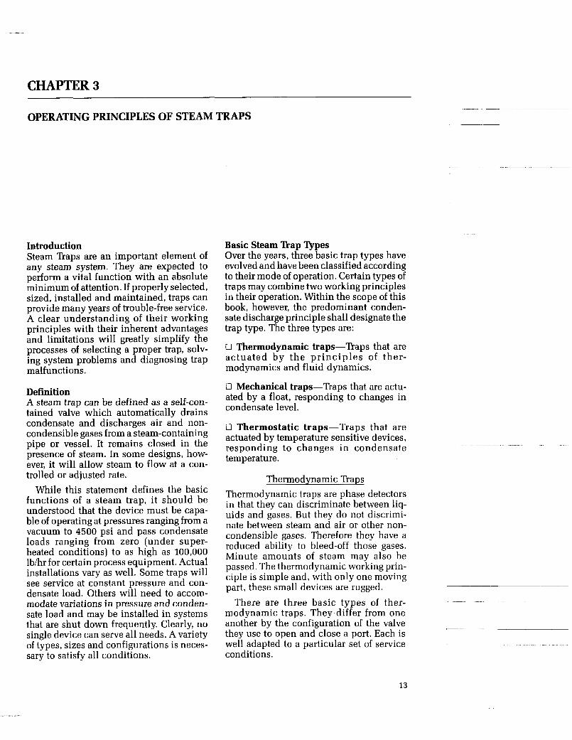
Outlet Port Flash Vapor Closes
Seating Surface Inlet Port I 1 Valve Disc I Bonnet Chamber
t Liquid Condensate i3 Flash Out
Steam & Condensate
in
Figure #3-1 Disc Rap
1. Disc naps-Disc traps utilize the heat energy in hot condensate and the kinetic energy in steam to open and close a valve disc, They are phase detectors, sensing the difference between liquid and gas or vapor.
During initial start-up, pressure created by cold condensate pushes the valve disc off the seating surface. This uncovers the inlet and outlet ports, allowing discharge. As condensate reaches the inlet port (a restriction), it experiences a decrease in pressure and an increase in velocity (in accordance with the laws of fluid dynam- ics). If the condensate is very close to steam temperature, the lower pressure will cause it to flash into steam (in accordance with the laws of thermodynamics). The result- ing high velocity flow beneath the disc, with its attendant localized pressure reduction under the disc, causes it to snap shut. Flow through the trap then stops until the pressure in the chamber over the disc decays sufficiently to allow the inlet pressure to force the disc off its seat. Con- densate then flows through the trap until once again it reaches such a velocity and lowering of pressure that flashing occurs and the disc can snap shut. This cycle con- tinuously repeats itself-the disc opening to allow the flow of condensate, and clos- ing on high velocity flash steam.
Disc traps are most frequently used in light condensate load applications and are known as “hot” traps-i.e., quickly dis- charging very hot condensate immediately after it forms.
Advantages: 0 Failure mode, gradually, predictably open over time. 0 Simple construction.
Small size and light weight. 0 Can be mounted in any position. 0 Rugged, withstands water hammer. 0 Self draining, not damaged by freezing.
Function not impaired by superheat. 0 Versatile, suitable for wide pressure range. 0 Condensate discharge temperature closely follows the saturation curve. 0 Performance is easily checked in field.
Disadvantages: 0 Marginal air handling capability. 0 Excessive backpressure in return sys- tems can prevent trap from closing. 0 Life is reduced significantly as pres-
0 High discharge noise level. 0 Dirt particles can increase cycle rate causing wear.
sures move above 300 psi. ~-
14
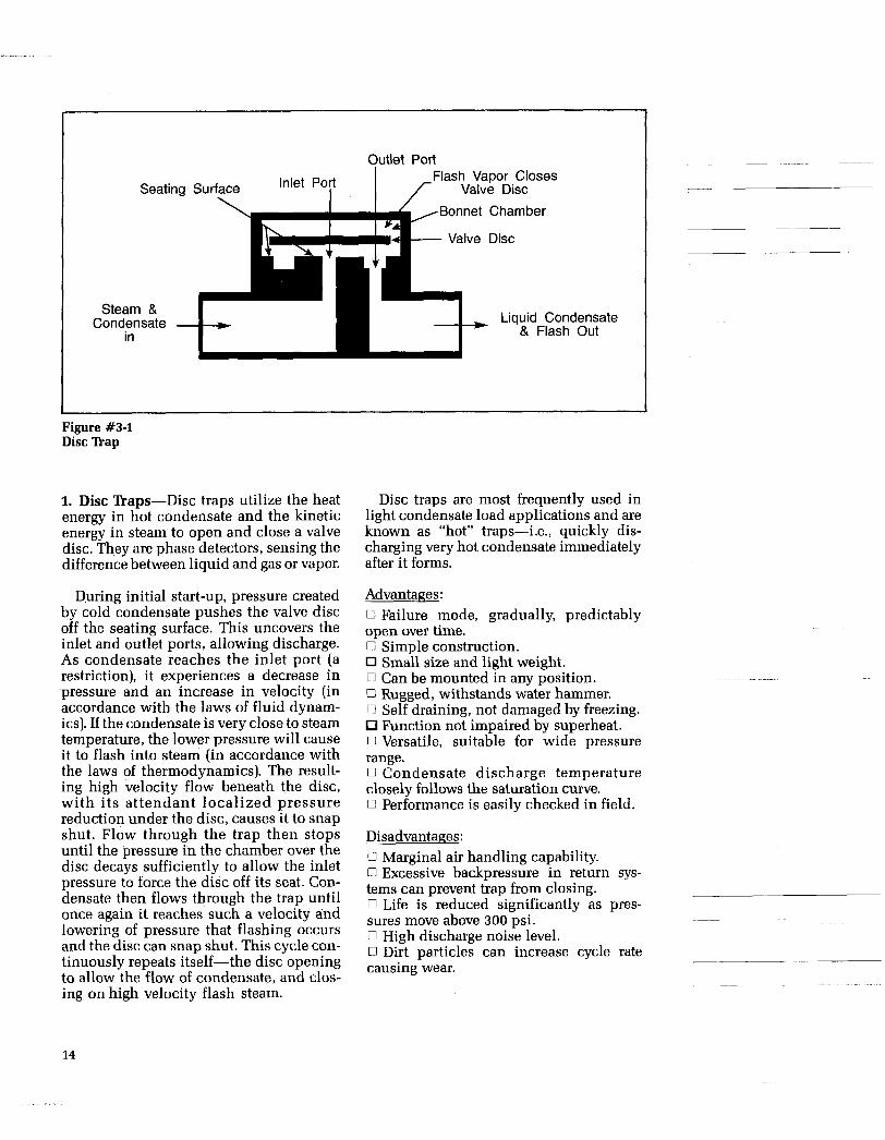
Flash Vapor Closes Piston Valve
I f Second Orifice (Control Orifice) First Orifice
Control Chamber
~ Liquid Condensate Steam & Condensate
in & Flash Out
Figure #3-2 Piston ’hap
2. Piston Paps-Piston traps utilize the heat energy in hot condensate, and the kinetic energy in steam, to open and close a valve. Like disc traps, they are phase detec- tors sensing the difference between a liq- uid and gas or vapor.
During initial start-up, pressure created by the cold condensate lifts the piston valve, allowing discharge of condensate. During this phase, the control chamber pressure is low because the second or con- trol orifice, can discharge more condensate than can be supplied to the control cham- ber through the first orifice. When the tem- perature of the discharging condensate is very close to steam temperature (i.e., sat- uration temperature), the condensate, experiencing the lower pressure of the con- trol chamber, will change into flash steam (in accordance with the laws of ther- modynamics). This flashing of the conden- sate in the control chamber chokes the flow through the control orifice, causing an increase in control chamber pressure. This increased pressure, acting on a larger effec- tive area of the piston valve than the inlet pressure, causes it to snap shut-prevent- ing steam flow through the trap. When cooler condensate reaches the trap, caus- ing the control chamber pressure to drop, flashing ceases and the trap re-opens to repeat the cycle.
The control orifice provides a continu-
ous discharge which is helpful in passing air or other non-condensable gases during start-up. The piston valve remains closed in the presence of steam because the pres- sure on top of the piston acts on a larger effective area than the inlet pressure under it. Steam loss through the control orifice is minimal.
Introduced in the 1930’s the piston trap was the first thermodynamic trap. It is a “hot” trap, providing excellent service in high pressure applications.
Advantages 0 Suitable for high pressure 0 Can be mounted in any position. 0 Good response to changing condensate load conditions. 0 Rugged, withstands water hammer. 0 Self-draining, not damaged by freezing. 0 Function not impaired by superheat. 0 Good air handling capability. 0 Primary failure mode-open. 0 Small size and light weight.
Disadvantages 0 Excessive backpressure in return sys- tems can prevent trap from closing. 0 Condensate discharge temperature fol- lows the saturation curve over a limited range. 0 Difficult to field check because of con- tinuous control flow discharge.
15

^ -
Flash Vapor Closes Lever
Lever \ / Control
Bonnet Chamber
Condensate - + Liquid Condensate & Flash Out
First Orifice Inlet Valve Discharge
Figure #3-3 Lever Rap
Bonnet Chamber
Steam &
in Condensate - +
Inlet Seat ' First Orifice Inlet Valve Discharge
Orifice Orifice)
- Liquid Condensate & Flash Out
3. Lever naps-Lever traps are a variation of the thermodynamic piston trap. They operate on the same principle as piston traps but with a lever action rather than a reciprocating piston action.
When the lever is closed, there is a lim- ited flow through the annulus between the inlet valve and its seat (first orifice) which then enters the control chamber and flows out through the second or control orifice. Incoming condensate pushes the lever upward with a tilting motion and full flow goes under it and out the discharge port. Condensate flowing past the inlet seat (a restriction) experiences a pressure drop (in accordance with the laws of fluid dynam- ics) and it will flash into steam (in accor- dance with the laws of thermodynamics) when the condensate temperature is very close to steam temperature (saturation tem- perature). The localized lower pressure under the lever (created by the high velocity flow of flash steam) causes the lever and inlet valve to snap shut. This prevents steam flow through the trap.
When condensate with its cooler tem- perature again reaches the trap, it will reopen, repeating the cycle.
The control orifice has a continuous dis- charge which is helpful in passing air and other non-condensible gases during start- up. Steam loss through the control orifice is minimal.
Lever traps are designed for applications having especially large condensate loads and that benefit from the very rapid dis- charge of condensate after its formation.
Advantages 0 Suitable for high pressure applications. 0 Good response to changing condensate load conditions. 0 Rugged, withstands water hammer. 0 Not damaged by freezing. 0 Function not impaired by superheat. 0 Good air handling capability. 0 Small, compact, easy to install and service.
Disadvantages ~
0 Excessive back pressure in return sys- tems can prevent trap from closing. 0 Difficult to field check due to continu- ous control flow discharge. ~
0 Can only be mounted in one position.
~
~
16
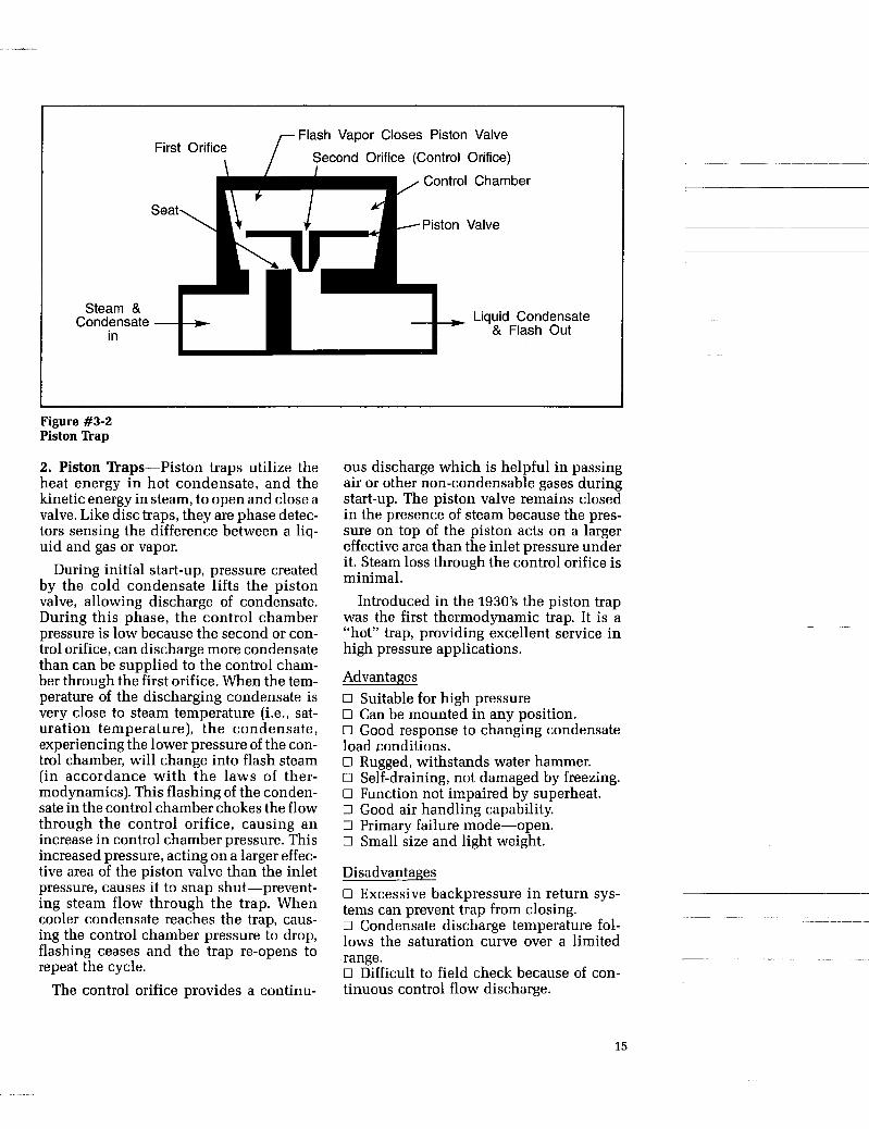
Figure #3-4 Cross-sectioned Bucket Trap
Mechanical Traps
Mechanical traps are density detectors and therefore also have difficulties venting air and non-condensible gases. Mechanical traps employ either an open or a closed float to actuate a valve. Closed float mechanical traps usually employ a secon- dary thermostatic air vent which allows the trap to discharge air rapidly. The air vent, of course, is an extra component which can fail open, causing the loss of steam, or fail closed and prevent the trap from discharg- ing condensate. Closed float traps are usually large in physical size. This, com- bined with a float that is fragile to external pressure, and the continuous presence of condensate within the trap, make this device unsuitable for high pressure appli- cations or installations where water hammer or freeze-ups can be expected.
On the positive side, these devices respond to changes in condensate level only, independent of temperature or pressure. They respond rapidly to chang- ing loads. Condensate discharge tem-
peratures follow closely the saturation curve and they have a modulating (rather than an on-off) type of discharge. They are extremely energy efficient.
Open float mechanical traps share many characteristics with closed float traps. One major difference, of course, is the open float as found in an inverted bucket trap. The open float is no longer a weak point, because it cannot be collapsed by excessive pressure. Venting is usually accomplished by means of a small vent hole in the top of the bucket. This is a compromise, as the efficiency of the trap is affected by the sizes of the vent. The larger the vent the better the air handling, but at the expense of higher steam losses. A smaller vent has the opposite effect. The end result is a trap that is relatively efficient, but which does not remove air rapidly during start-up condi-
with an on-off action and the discharge temperature follows the saturation curve. All mechanical traps are position-sensitive and can be installed only in their intended orientation.
~~ tions. It discharges near steam temperature ~~
17

Steam & Condensate in
Steam Space 1
Condensate - Level
Figure #3-5 Float and Thermostatic Trap
h-%rAir + ... . . . . . . . . . . . . .
Vent
, . . . . . . . . .
Liquid Condensate Float Lever Seat ’ & Flash Out
1. Closed Float traps-Although it is one of the oldest on the market, the closed float trap is still in widespread use. The opening and closing of the valve is caused by changes of the condensate level within the trap shell.
When the trap is empty, the weight of the float closes the valve. As condensate enters the trap, the float rises and opens the valve, allowing condensate to be discharged. The float is designed to provide sufficient force to overcome the differential pressure across the valve. The internal float and valve configuration is such that the con- densate level is always above the valve, thus creating a continuous water seal at its seat. Actual construction varies widely depending upon the manufacturer. While most designs employ a linkage-pivot sys- tem, one particular design uses no linkage at all and relies on a free floating ball to achieve the desired action.
An inherent disadvantage of a simple float trap is that it cannot discharge air or non-condensible gases. It is therefore nec- essary to ins ta l l a n auxi l iary ther-
mostatically activated air vent. For this reason, these traps are known as float and thermostatic or F & T traps.
Advantages 0 Unaffected by sudden or wide pressure changes. 0 Responds very quickly to condensate load changes. 0 Continuous discharge. 0 Condensate discharge temperature closely follows the saturation curve. 0 Function is not impaired by high back pressures. 0 Energy efficient. 0 Simple construction. Disadvantages 0 Relatively large and heavy. 0 Float easily damaged by water hammer. 0 Does not withstand freezing. 0 Can be mounted only in one position. 0 Sui t ab le only for re la t ive ly low pressures. 0 Requires auxiliary air vent which is an additional source of failure.
Primary failure mode is closed. 0 Not self draining.
~~ ~
18

Liquid Condensate Flash Out
&
Valve
Lever
Seat Axa; SdSoa,Cde,S,sate Level -Steam Bubbles
Vent Hole L Inverted Buck
Steam & Condensate
et
in
Figure #3-6 Inverted Bucket Trap
2. Inverted Bucket Traps-Inverted bucket traps are members of the mechan- ical trap family, using an open “inverted bucket” as a float. The trapping principle utilizes the difference in density between steam and water.
The construction of the trap is such that the trap inlet leads into the bottom and open end of the inverted bucket. Discharge is through a n out le t valve above the inverted bucket.
Steam entering the inverted and sub- merged bucket, causes it to float and close the outlet valve, preventing discharge of steam. Steam in the bucket both condenses and leaks through the vent, allowing the bucket to sink and open the valve to dis- charge condensate. The weight of the bucket must be sufficient to overcome the closing force created by the differential pressure across the valve. Inverted bucket traps discharge condensate intermittently very near saturation temperature.
Any air or non-condensible gases enter- ing the trap will also cause the bucket to float and the valve to close. Since they can- not condense as steam does, those gases
will cause the trap to remain closed. In order to overcome this problem, the bucket has a hole to vent air and steam. The size of this vent hole has to be relatively small to prevent excessive loss of steam in addi- tion to the air.
While most inverted bucket traps utilize a linkage system to obtain their desired action, one particular design uses no link- age at all and uses a free floating open spherically-shaped float in its design execution.
Advantages 0 Simple construction. 0 Rugged. 0 Condensate discharge temperature closely follows the saturation curve. 0 Reliable. Disadvantages 0 Marginal air handling during start-up. 0 Not self draining; subject to freeze ups. 0 Not suitable when superheat is present. 0 Can lose prime, and is not self-priming. 0 Can be mounted only in a single position. 0 Failure mode is unpredictable (open or closed).
19

Liquid
& Flash out
Condensate 7
Steam Space
/ Open Bucket
Valve Seat /
/ . /Air Vent p! . . . . . . . .
I .
Steam & condensate
in
Condensate Level
-Siphon Tube
Figure #3-7 Open Bucket Trap
3. Open Bucket nap-Open bucket traps are rarely used today. As with other mechanical traps, they utilize the dif- ference in density between steam and water.
When condensate first enters the trap, it fills the trap body and causes the bucket to rise and close the valve at the top of the trap. If entrapped air is removed, conden- sate will continue to enter the trap, finally spilling over into the bucket. This causes it to sink and open the valve allowing dis- charge of condensate. When steam arrives, it pushes the condensate out of the bucket through the syphon tube, which in turn refloats the bucket and closes the valve. As the steam in the trap condenses, additional condensate enters the trap and the cycle is repeated.
This type of trap requires an auxiliary thermostatically activated air vent, similar
to that used in the float & thermostatic trap. Advantages 0 Simple construction. 0 Reliable. 0 Condensate discharge temperature closely follows the saturation curve. 0 Function not impaired by high back pressure. 0 Fast response to changing condensate loads. Disadvantages 0 Not self draining; subject to freeze ups. 0 Not suitable when superheat is present. 0 Can lose prime, not self-priming. 0 Can be mounted only in a single position. 0 Requires auxiliary air vent which is an additional source of failure.
pressures. 0 Relatively large and heavy.
~~
0 Sui tab le on ly for relatively low __ ~
~
20
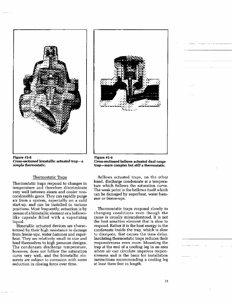
Figure #3-8 Cross-sectioned bimetallic actuated trap-a simple thermostatic.
Thermostatic Traps Thermostatic traps respond to changes in temperature and therefore discriminate very well between steam and cooler non- condensible gases. They can rapidly purge air from a system, especially on a cold start-up, and can be installed in various positions. Most frequently, actuation is by means of a bimetallic element or a bellows- like capsule filled with a vaporizing liquid.
Bimetallic actuated devices are charac- terized by their high resistance to damage from freeze-ups, water hammer and super- heat. They are relatively small in size and lend themselves to high pressure designs. The condensate discharge temperature, however, does not follow the saturation curve very well, and the bimetallic ele- ments are subject to corrosion with some reduction in closing force over time.
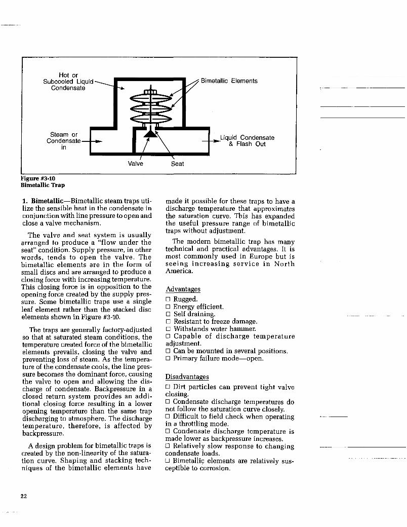
Figure #3-9 Cross-sectioned bellows actuated dual range trap-more complex but still a thermostatic.
Bellows actuated traps, on the other hand, discharge condensate at a tempera- ture which follows the saturation curve. The weak point is the bellows itself which can be damaged by superheat, water ham- mer or freeze-ups.
Thermostatic traps respond slowly to changing conditions even though the cause is usually misunderstood. It is not the heat sensitive element that is slow to respond. Rather it is the heat energy in the condensate inside the trap, which is slow to dissipate, that causes the time delay. Insulating thermostatic traps reduces their responsiveness even more. Mounting the trap at the end of a cooling leg in an area where air can circulate improves respon- siveness and is the basis for installation instructions recommending a cooling leg at least three feet in length.
21
Hot or Subcooled Liquid -1-1 A Bimetallic Elements
Condensate I r t- Steam or
Condensate in
Liquid Condensate & Flash Out
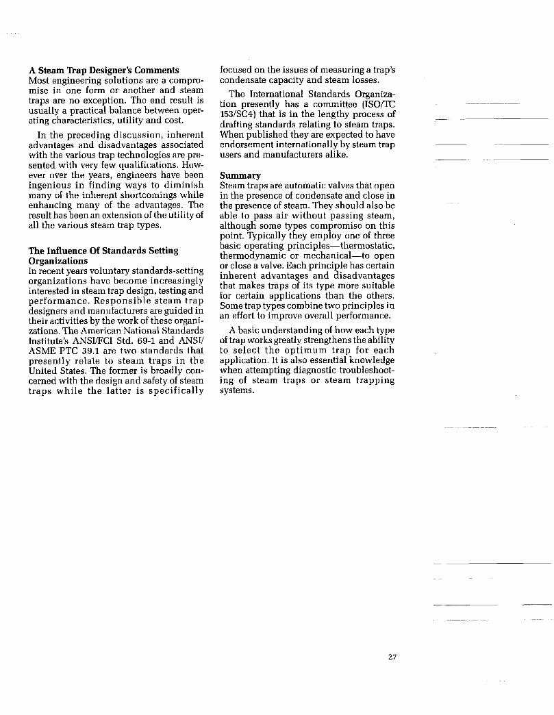
Figure #3-10 Bimetallic Trap
1. Bimetallic-Bimetallic steam traps uti- lize the sensible heat in the condensate in conjunction with line pressure to open and close a valve mechanism.
The valve and seat system is usually arranged to produce a “flow under the seat” condition. Supply pressure, in other words, tends to open the valve. The bimetallic elements are in the form of small discs and are arranged to produce a closing force with increasing temperature. This closing force is in opposition to the opening force created by the supply pres- sure. Some bimetallic traps use a single leaf element rather than the stacked disc elements shown in Figure #3-10.
The traps are generally factory-adjusted so that at saturated steam conditions, the temperature created force of the bimetallic elements prevails, closing the valve and preventing loss of steam. As the tempera- ture of the condensate cools, the line pres- sure becomes the dominant force, causing the valve to open and allowing the dis- charge of condensate. Backpressure in a closed return system provides an addi- tional closing force resulting in a lower opening temperature than the same trap discharging to atmosphere. The discharge temperature, therefore, is affected by backpressure.
A design problem for bimetallic traps is created by the non-linearity of the satura- tion curve. Shaping and stacking tech- niques of the bimetallic elements have
made it possible for these traps to have a discharge temperature that approximates the saturation curve. This has expanded the useful pressure range of bimetallic traps without adjustment.
The modern bimetallic trap has many technical and practical advantages. It is most commonly used in Europe but is seeing increasing serv ice i n North America.
Advantages 0 Rugged. 0 Energy efficient. 0 Self draining. 0 Resistant to freeze damage. 0 Withstands water hammer. 0 Capable of discharge temperature adjustment. 0 Can be mounted in several positions. 0 Primary failure mode-open.
Disadvantages 0 Dirt particles can prevent tight valve closing. 0 Condensate discharge temperatures do not follow the saturation curve closely. 0 Difficult to field check when operating in a throttling mode. 0 Condensate discharge temperature is made lower as backpressure increases. 0 Relatively slow response to changing condensate loads. 0 Bimetallic elements are relatively sus- ceptible to corrosion.
22

Steam and/or
Depending on Trap
Hot Condensate C , 1 \ (, h Bellows
c , 3
Steam &
in Condensate - + --
nent
Liquid Condensate
& Flash out
/ Seat
Figure #3-11 Bellows Trap
2. Bellows Traps-Bellows traps are ther- mostatic traps that respond to changes in the temperature and pressure of the steam supply to open and close a valve. The valve actuator is a capsule or bellows filled with a vaporizing liquid, and having both a fixed and a free moving end, it opens or closes the valve in response to internal pressure changes. The most frequently used actuating element is a corrugated bellows. Single-diaphragm capsules are also used but provide a correspondingly shorter stroke.
This simple operating principle pro- vides many desirable operating charac- teristics. For example, the number of degrees below steam temperature at which the trap will open can be varied so the trap provides either a “hot” or “cold” discharge. Also the normal failure mode (open or closed) can be changed.
The characteristics of the actuating system can be affected by the liquid fill and natural free length of the actuator. The principles can best be explained by con- sidering a bellows, even though they apply equally well to single diaphragm capsules.
Modern bellows/diaphragm traps have been improved in design, construction and materials to minimize their inherent disad- vantages. Today they play an important role in steam trap application.
Concepts Defined 0 Natural free length-length of the bel- lows assembly before it is sealed.
0 Assembled free length-length of the bellows assembly after it is sealed, in its cold (contracted) condition.
In the most common arrangement, the bellows is located upstream of the valve and thus senses upstream conditions. Flow direction is over the seat tending to close the valve. During cold start-up, the bellows is contracted, allowing condensate and air to be discharged. As the temperature of the flowing medium rises, the bellows also gets hot, the liquid inside it vaporizes and expands (strokes) the bellows to close the valve. Failure of this type of trap generally refers to the rupture of the bellows. After such a rupture, the bellows will return to its natural free length which can be designed so that the trap will be in either an open or closed condition. 0 Fail open design-This definition implies that the natural free length must contract the bellows away from the seat. To make this arrangement functional, the bel- lows must be filled with a liquid having a boiling point lower that that of water, because for the bellows to expand, the internal pressure must be higher than the external steam pressure.
Low boiling point liquids, such as alco- hols or ether, are frequently used in bel- lows but have the disadvantage that their saturation curve does not exactly corre- spond to that of steam. As a result steam traps having such a bellows will discharge condensate having different, levels of sub- cooling over a wide pressure range.
23

0 Fail closed design-This definition implies that the bellows remain expanded upon rupture. This can be accomplished by evacuating the bellows initially to obtain a contracted assembled free length. During normal operation when the bellows is hot, the pressure inside the bellows will approach the steam supply pressure, caus- ing it to expand. Evacuated bellows are usually filled with water. The inherent advantage is that the condensate discharge temperature of traps having such a bellows will closely follow the steam saturation curve.
Advantages 0 Excellent air handling capability. 0 Energy efficient. 0 Self draining.
0 Various condensate discharge tempera- tures available depending on bellows design. 0 Condensate discharge temperature fol- lows the saturation curve. -- 0 Can be mounted in several positions. 0 Simple construction. 0 Small size and weight. Disadvantages 0 Bellows elements tend to be failure prone, especially when subjected to water hammer. 0 Difficult to field check when operating in a throttling mode. 0 Generally not suited for high pressure applications. 0 Limited superheat capability. 0 Short stroke diaphragm design suscepti- ble to dirt initiated failures.
~ ~~~ ~ ~ ~~~~
24

Adjustment Mechanism
/ Thermostatic Element
Over Temperature Spring
Return SDrina
I Seat
\ Valve Plug
Figure #3-12 Wax Capsule Trap
3. Liquid or Solid Expansion n a p (Wax Capsule Type)-Liquid or solid expansion traps are finding limited application today.
The opening and closing of these traps is a function of temperature and balanced return spring forces. Elevated tempera- tures cause an expansion of the thermo- static element which closes the valve, while low temperatures cause a contrac- tion of the element, aided by the spring, which results in opening the valve.
Traditionally, the thermostatic actuator has been in the form of a metal rod, having a high thermal coefficient of expansion, or an elastic metallic capsule (bellows) filled with a liquid which expands when heated. In recent years design innovation has intro- duced a small diaphragm actuator filled with a wax-like substance which expands rapidly at a preselected temperature. This has significantly reduced trap size and increased the speed of response relative to the more traditional design. Figure #3-12 shows the working internals typical of a newer wax capsule expansion trap.
Regardless of design variations, these traps have one characteristic in common. The temperature of the condensate they
discharge remains constant at a predeter- mined point and is not a function of steam supply pressure. All other steam trap types have a condensate discharge temperature that increases with steam supply pressure.
In general, these constant discharge tem- perature traps respond slowly to changes in temperature and should only be spec- ified where subcooled discharge with resultant condensate back-up is desired.
Advantages 0 Rugged. 0 Good air handling capability. 0 Resistant to freeze damage. 0 Withstands water hammer. 0 Can be mounted in any position. 0 Self draining. 0 Primary failure mode is open.
Disadvantages 0 Dirt particles can prevent tight close.
Difficult to field check. 0 Slow response to changing condensate loads. 0 Actuator damaged by exposure to high temperature.
0 Requires substantial subcooling. ~ ~~
~
25

Steam, Flash, or Liquid in Intermediate
I Chamber
Steam, and/or Steam & - Condensate &
in Vapor Out Condensate Flashing
First Orifice Second Orifice
Figure #3-13 Fixed Orifice Trap
Orifice Traps Orifice traps are seldom used because of
their inherent limitations in application range. This device consists of one or more successive orifices. Where two or more ori- fices are used, condensate passes through a number of successive chambers where flashing occurs. This, in turn, creates a restricting or choking effect and allows the use of larger and less dirt sensitive orifices for a given condensate capacity. In some design executions, these orifices are adjustable valves.
Advantages 0 No moving parts. 0 Suitable for high pressure application. 0 Rugged, withstands water hammer.
0 Not damaged by freezing. 0 Function not impaired by superheat. 0 Can be mounted in any position.
Disadvantages 0 Orifice size must be carefully selected for each installation. 0 Can not respond to varying condensate loads. 0 Inefficient if oversized. 0 Dirt particles readily impair perfor- mance. 0 Difficult to field check because of con- tinuous discharge.
In the absence of condensate, the trap passes live steam.
26
.I
A Steam Trap Designer’s Comments Most engineering solutions are a compro- mise in one form or another and steam traps are no exception. The end result is usually a practical balance between oper- ating characteristics, utility and cost.
In the preceding discussion, inherent advantages and disadvantages associated with the various trap technologies are pre- sented with very few qualifications. How- ever over the years, engineers have been ingenious in finding ways to diminish many of the inherept shortcomings while enhancing many of the advantages. The result has been an extension of the utility of all the various steam trap types.
The Influence Of Standards Setting Organizations In recent years voluntary standards-setting organizations have become increasingly interested in steam trap design, testing and performance. Responsible steam trap designers and manufacturers are guided in their activities by the work of these organi- zations. The American National Standards Institute’s ANSI/FCI Std. 69-1 and ANSI/ ASME PTC 39.1 are two standards that presently relate to steam traps in the United States. The former is broadly con- cerned with the design and safety of steam traps while the latter is specifically
focused on the issues of measuring a trap’s condensate capacity and steam losses.
The International Standards Organiza- tion presently has a committee ( I S O m 153/SC4) that is in the lengthy process of drafting standards relating to steam traps. When published they are expected to have
users and manufacturers alike. endorsement internationally by steam trap ~~
Summary Steam traps are automatic valves that open in the presence of condensate and close in the presence of steam. They should also be able to pass air without passing steam, although some types compromise on this point. Typically they employ one of three basic operating principles-thermostatic, thermodynamic or mechanical-to open or close a valve. Each principle has certain inherent advantages and disadvantages that makes traps of its type more suitable for certain applications than the others. Some trap types combine two principles in an effort to improve overall performance.
A basic understanding of how each type of trap works greatly strengthens the ability to select the optimum trap for each application. It is also essential knowledge when attempting diagnostic troubleshoot- ing of steam traps or steam trapping systems.
27
CHAPTER 4
PRINCIPLES OF STEAM TRAP APPLICATION
The actual procedure of matching a steam trap to the needs of the application is to perform the “sizing” first and the “selection” second. Basic definitions of sizing and selection are presented in that sequence. However, to have a more complete background and understanding of the sit- uation, the Application Universe is first discussed in some detail, followed by a discussion on the Selection Process, and then the Basic Sizing Steps. You are also referred to Appendix A for more detailed profiles on specific applications.
Introduction Steam trap application is the process of matching a steam trap to the needs of a steam system and its associated equipment. This involves a two-step process:
I. Sizing it correctly
2. Selecting a suitable type of steam trap
Steam trap sizing has been mistakenly limited by many to matching the end con- nection size of a trap to the particular pipe size being used to drain a piece of steam heated equipment. Sizing in its correct sense is matching the steam condensing rate (in pounds per hour) of a piece of equipment (at its particular pressure and temperature conditions) to the rated con- densate discharge capabilities of a suitable steam trap.
These steps are described in detail in this chapter. However, it must be emphasized that two additional steps are required to assure successful steam trapping results. Chapter 5 discusses the elements that are important to the proper installation of a steam trap and Chapter 6 describes the key to long-term success-proper mainte- nance.
Sizing and selection of the correct trap for a given application can be complicated by a number of variables, but there are some guiding principles that can make for a logical selection process. They will be discussed in this chapter. Some simplify- ing rules of thumb, which can be helpful when quick decisions must be made, will also be presented.
Trap manufacturers are prepared to make sizing calculations to determine conden- sate loads in support of their selling efforts. Small plants having only a few stream traps tend to rely heavily on the trap manufac- turer for sizing guidance. Engineering con- tractors and large plants using many steam traps generally make their own sizing cal- culations. Examples of several sizing cal- culations are shown later in this chapter.
0 Steam Trap Selection: This is primarily the process of choosing the type of trap, from one of the major trap technologies (mechanical, thermostatic, thermo- dynamic) that will provide the combina- tion of performance characteristics most closely matching the needs of both plant and equipment.
Selection secondarily includes making Basic Definitions judgments about the usefulness of certain 0 Steam Trap Sizing: This is the process accessories and features which are of choosing a trap which has the capabili- included in some trap designs, as well as ties to meet the operating conditions of making judgments about the advantages of pressure, temperature and condensate choosing to do business with one trap drainage rate for a given application. manufacturer in preference to another.
29
Trap Application Universe It is possible to classify steam trap applica- tions in a number of different ways. This book addresses itself to the field of indus- trial steam trapping in contrast to the steam trapping associated with the low- pressure (below 15 psi) heating, ventilating and air conditioning field. There is some overlap, of course, but industry has tended to recognize these two major classifica- tions of users.
Industrial steam trapping applications are themselves typically divided into two major classifications:
Protection Service 0 Steam main drip: drainage of the con- densate that normally forms in the pipes delivering steam from a boiler to a specific point of use. This helps prevent damaging
water hammer and promotes the delivery of dryer steam to plant equipment.
0 Steam tracing: drainage of the conden- sate that normally forms in the small steam lines or steam jackets used to heat valves,
pipelines during freezing conditions or when product temperatures must be main- tained at specified levels.
Process Service
0 Steam using Equipment: drainage of the condensate that normally forms when steam is used to heat liquids, gases or solids.
These various classifications of steam traps are presented in the simplified matrix shown in Figure #4-1.
field instruments, and the liquids in larger ~~ ~~~
30
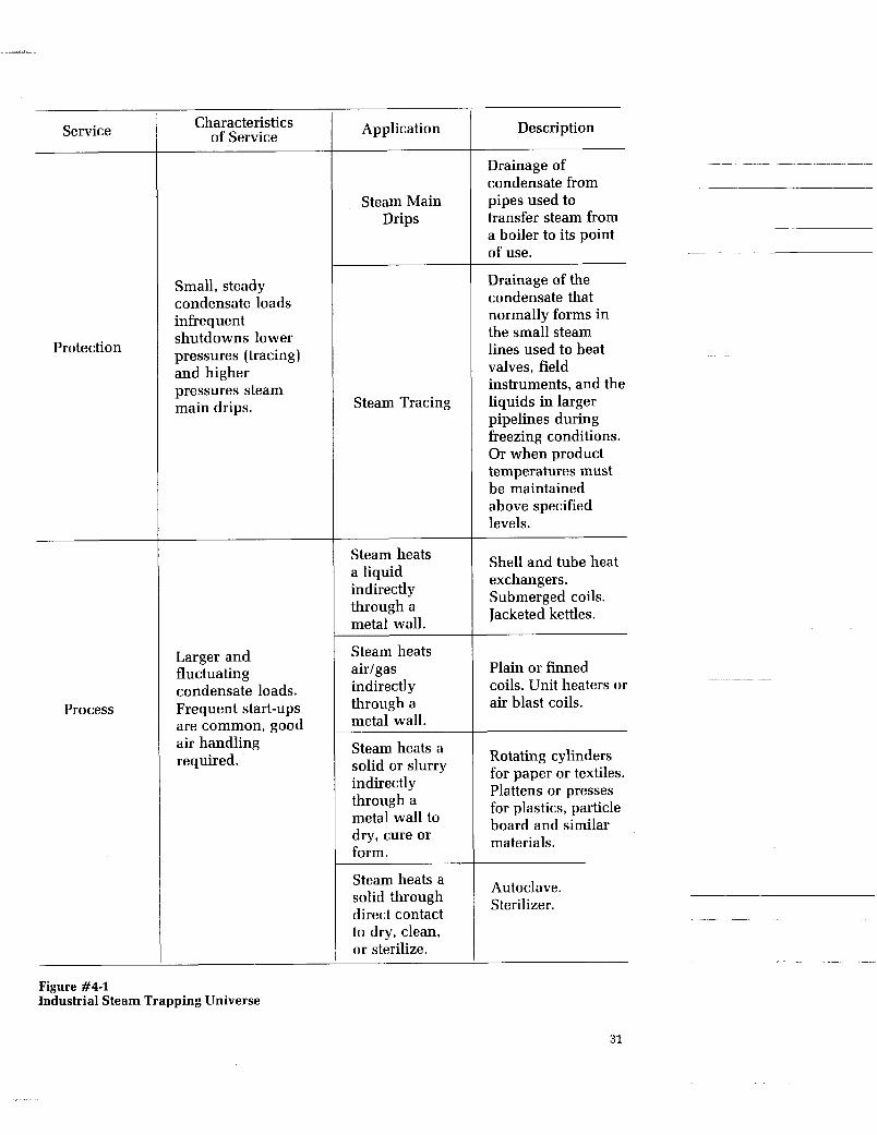
Service
Protection
Process
Characteristics of Service
Small, steady condensate loads infrequent shutdowns lower pressures (tracing) and higher pressures steam main drips.
Larger and fluctuating condensate loads. Frequent start-ups are common, good air handling required.
Application
Steam Main Drips
Steam Tracing
Steam heats a liquid indirectly through a metal wall.
Steam heats airlgas indirectly through a metal wall.
Steam heats a solid or slurry indirectly through a metal wall to dry, cure or form.
Steam heats a solid through direct contact to dry, clean, or sterilize.
Description
Drainage of condensate from pipes used to transfer steam from a boiler to its point of use.
Drainage of the condensate that normally forms in the small steam lines used to heat valves, field instruments, and the liquids in larger pipelines during freezing conditions. Or when product temperatures must be maintained above specified levels.
Shell and tube heat exchangers. Submerged coils. Jacketed kettles.
Plain or finned coils. Unit heaters or air blast coils.
Rotating cylinders for paper or textiles. Plattens or presses for plastics, particle board and similar materials.
Autoclave. Sterilizer.
Figure #4-1 Industrial Steam Trapping Universe
31

Steam Pressures
Condensate Load
Low Medium Heavy Very Heavy - ~~~ ~ ~ ~~ ~
__I___ 'Oo0 lbhr over 10,000 lbhr 100 lbhr to to loo lbhr 1000 lbh r to 10,000 lbhr
Tracing 81 drip Low 15 psi-100 psi
I I Drip 1 P R O C E S S A P P L I C A T I O N S
300 psi-600 High psi I I I
~~~ ~~~ I I
P R O C E S S A P P L I C A T I O N S
Drip Very High Over 600 psi
Medium 100 psi-300 psi
Figure #4-2 Industrial Trapping Applications Universe
I I Tracing 8t drip P R O C E S S A P P L I C A T I O N S
An alternative way of looking at the steam trap application universe is by clas- sifications of steam pressure and conden- sate load. Figure #4-2 shows the ranges of pressure a n d load most commonly encountered in different applications. By its very nature such a matrix tends to be arbitrary, but it does show the general picture.
If the number of traps in the industrial world were summarized by steam pressure and condensate load, and listed in the appropriate quadrant of the matrix, the largest numbers by far would be in the low pressure, low condensate load quadrant. The numbers would rapidly decrease as the loads and pressure increase.
Since no single trap design or principle of operation is suitable for use across such a wide range of pressures and condensate loads, preparation of a matrix similar to Figure #4-2 is sometimes used as a tech- nique to assist a large plant in standardiz- ing on the smallest variety of traps for its use. Chapter VI, Maintenance, describes further the process of establishing plant standards.
The Steam n a p Selection Process The steam trap selection process starts with a description of a plant's need. Unfor- tunately, simply stating that need in terms of equipment to be served-such as a soup kettle, tire vulcanizing press, or an air heater-is not adequate. While it is impor- tant information, it is not sufficient to assure that all the requirements of a spe- cific installation will be met in a satisfac- tory manner.
Selecting a trap, like selecting an auto- mobile, requires an indication of user pref- erence with respect to a rather large number of criteria. Fuel economy versus performance, comfort and safety versus cost, latest style versus an established model with proven reliability are familiar car selecting choices. While the factors that are evaluated in selecting a steam trap are not nearly as familiar, they are no less important in making a successful decision. They can be classified into several levels of importance. Such a list can then be used as a basis for assuring that &l the significant requirements of a particular application are considered. Figure #4-3 summarizes and classifies the most significant steam trap selection criteria.
~
32
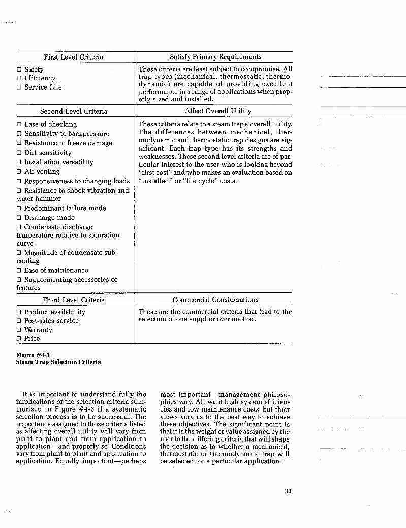
First Level Criteria
0 Safety 0 Efficiency 0 Service Life
Second Level Criteria
0 Ease of checking 0 Sensitivity to backpressure 0 Resistance to freeze damage 0 Dirt sensitivity 0 Installation versatility 0 Air venting 0 Responsiveness to changing loads 0 Resistance to shock vibration and water hammer 0 Predominant failure mode 0 Discharge mode 0 Condensate discharge temperature relative to saturation curve 0 Magnitude of condensate sub- cooling 0 Ease of maintenance 0 Supplementing accessories or features
Third Level Criteria
0 Product availability 0 Post-sales service 0 Warranty 0 Price
Figure #4-3 Steam Trap Selection Criteria
Satisfy Primary Requirements
These criteria are least subject to compromise. All
dynamic) are capable of providing excellent performance in a range of applications when prop- erlv sized and installed.
trap types (mechanical, thermostatic, thermo- ~~~~ ~ ~~~~~
~
Affect Overall Utility __
These criteria relate to a steam trap’s overall utility. The differences between mechanical, ther- modynamic and thermostatic trap designs are sig- nificant. Each trap type has its strengths and weaknesses. These second level criteria are of par- ticular interest to the user who is looking beyond “first cost” and who makes an evaluation based on “installed” or “life cycle” costs.
~
Commercial Considerations
These are the commercial criteria that lead to the selection of one supplier over another.
It is important to understand fully the implications of the selection criteria sum- marized in Figure #4-3 if a systematic selection process is to be successful. The importance assigned to those criteria listed as affecting overall utility will vary from plant to plant and from application to application-and properly so. Conditions vary from plant to plant and application to application. Equally important-perhaps
most important-management philoso- phies vary. All want high system efficien- cies and low maintenance costs, but their views vary as to the best way to achieve these objectives. The significant point is that it is the weight or value assigned by the user to the differing criteria that will shape the decision as to whether a mechanical, thermostatic or thermodynamic trap will be selected for a particular application.
33

A more detailed discussion of the steam trap selection criteria listed in Figure #4-3 is provided below:
0 Safety: Product safety results when a good design is well manufactured and properly used. In the United States, the American National Standards Institute (ANSI) describes for the manufacturer, both design and testing standards that relate to factors affecting product safety. Manufacturers can describe installation and maintenance practices they know to be successful, but safety in the plant ulti- mately rests with the user.
0 Service Life: A long lasting steam trap is obviously desirable. Regardless of design, however, every steam trap’s life is shortened as steam pressures and temperatures increase. Hot condensate is a particularly difficult liquid to handle. It can be both corrosive and erosive and, under certain conditions, it can cause cavitation. It can destroy valves and seating faces in a matter of days in extreme circumstances. The fre- quency with which a trap must open and shut also obviously influences its life span. Opposing these destructive forces are the designer’s skills, hardened materials and the level of special concern a plant has for selecting and sizing traps suitable for the conditions they will experience.
0 Efficiency: The most efficient steam trap is one that has failed in the closed position because it wastes no steam. Obviously effi- ciency can not properly be considered without reference to how a trap performs its other functions. Claims that one trap type is more efficient than another are as difficult to support as they are to refute. Given a calorimeter test in a laboratory, vir- tually every major trap type can achieve efficiencies of or close to 100%. In fact, the differences in efficiency between traps will often be unmeasurable because they are less than the accuracies of the testing equipment.
below steam temperature. As a conse- quence, it can be made to back up suffi- cient condensate that steam is unable to reach the trap and pass through it in normal service. This condensate backup, however, is not always desirable because it may adversely affect the efficiency of the system. Thermal efficiency of the steam system in which a steam trap is installed is more important to the user than the effi- ciency of the steam trap. A steam trap may be very efficient but if it backs condensate into a heat exchanger -thereby reducing system efficiency-it is unsuited for this particular application. The same trap backing up condensate in certain tracing applications can be contributing to system efficiency by utilizing the sensible heat in the condensate. Clearly, steam trap effi- ciency is very important, but overall system efficiency is even more important, and steam trap selection should be made with this fact in mind.
0 Ease of Checking: Considering the difficulties inherent in detecting whether a steam trap is performing properly (see Chapter VI “Maintenance”), it is surprising more consideration isn’t given to this criterion. A trap that has a crisp open-close cycle can quickly be judged to be healthy with a simple listening device. Traps that modulate or have a slower and softer open- close cycle often leave the steam trap checker uncertain about their condition. “Is it capable of shutting off tightly?’iis the nagging question. As a group, traps that normally provide modulating control- such as the float and thermostatic or the bimetallic thermostatic-are more difficult to check than other trap types.
0 Sensitivity to Backpressure: Traps dis- charging into closed condensate return systems will experience varying amounts of backpressure, depending on the return system’s design and the number and condi- tion of other traps discharging into it. Most bimetallic traps will discharge condensate at progressively cooler temperatures as they experience increasing backpressures. Thermodynamic traps tend to decline in efficiency as backpressures exceed 50% of the inlet pressure.
If there is one trap type that is theoreti- cally superior from the standpoint of effi- ciency, it is probably the thermostatic because its opening temperature can be
34
0 Resistance to Freeze Damage: Steam lines shut down for maintenance or by accident, or condensate return lines reduced to very slow or sluggish flow because of dirt or accumulated scale, are all subject to freezing in cold weather. The degree of concern by plant managers for damage to equipment and lost production is quite different between the Gulf Coast and Canada for obvious reasons. Some steam traps are inherently more suscepti- ble to damage by freezing than others by virtue of their design and materials of con- struction. Cast iron body bucket and float traps are not popular for use out of doors in cold climates because they require an inter- nal water reservoir which makes them especially vulnerable to freezing prob- lems. In addition the piping configuration used for their installation often makes system drainage difficult. By contrast, bimetallic thermostatic and thermo- dynamic traps are free of this problem. 0 Dirt Sensitivity: All steam traps can be put out of commission by pipeline scale, pipe joint sealants, oxide build-up or simi- lar forms of contamination. Typically, dirt is caught between a trap’s valve and seat. This prevents tight shut-off, allows steam leakage and very quickly causes perma- nent erosion damage to these sealing faces. Some thermostatic, thermodynamic and bucket traps will have their smaller passage or vent holes closed by oxide build-up. Knowledgeable engineers will carefully consider the relative suscep- tibility of various trap types to contamina- tion by dirt before selecting a trap for their plant. 0 Installation Versatility: Some steam trap models (such as thermostatic or ther- modynamic types), can be installed suc- cessfully in either a horizontal or vertical line. This simplifies the inventory, store- keeping and installation problems of the plant. Mechanical traps do not easily lend themselves to this flexibility of use, thus often creating the need for specific models for installation into either horizontal or vertical lines.
Air Venting: In start-up situations, air must be vented from pipe lines and equip- ment before steam can enter it. The faster it is vented, the more quickly equipment is brought up to temperature. Some steam
traps-such as thermostatic types-pass air very quickly under these conditions,
bucket traps release air much more slowly. If equipment is started and shutdown fre- quently, as in many process applications, good air venting is an especially important consideration in determining the type of trap to be installed.
Installations which operate around-the- clock for months at a time are less con- cerned with this special start-up capa- bility, but they still require the ability to pass non-condensable gases such as car- bon dioxide (CO,) that may accumulate in a condensate return system.
while thermodynamic disc traps and ~ ~~ ~
~~ - ~~~
0 Responsiveness to Changing Loads: Not all trap types accommodate themselves quickly to the changing condensate loads typical of process applications. Mechan- ical and thermodynamic traps are very responsive, but thermostatic traps must first cool slightly before they can open wider to pass a greater amount of conden- sate. An adequate “cooling leg” is required in front of thermostatic traps to assure good system efficiency.
Resistance to Shock, Vibration & Water Hammer: Despite the system designer’s best efforts, all steam systems tend to expe- rience some level of vibration, shock, or water hammer. Start-ups, pressure changes or changing loads, are the periods that gen- erally are the hardest on equipment such as steam traps. Not all traps however, are equally vulnerable to damage from these causes. Thermodynamic traps and bi- metallic thermostatic traps are generally very rugged. The bellows in thermostatic traps and the closed float in some mechan- ical traps are fragile and damage-prone. These damage producing conditions are most frequently seen in process appli- cations.
0 Predominant Failure Mode: All traps are susceptible to failing closed when plugged with dirt. But, apart from this spe- cial case, some types of trap normally fail in the open position while others will typ- ically fail in the closed position. Thermo- dynamic traps and bimetaIlic traps fail open when they are worn out. Bucket traps tend to have an unpredictable failure mode as they can fail in the open position with a
35

loss of prime, or they can fail closed if the bucket vent becomes clogged or the trap experiences pressure differentials above that allowable for the trap’s orifice size. Bellows thermostatic traps will fail either open or closed (depending on the design of the bellows) if the bellows is damaged.
Opinions differ concerning the desir- ability of one failure mode over the other. A trap “failed closed” is not losing steam. On the other hand, a trap however wasteful, that has failed open, maintains condensate drainage and therefore has not interfered or disrupted the process. In general it would seem that preserving the process is the higher need and a trap that fails open is more desirable than one that fails closed.
0 Discharge Mode (cyclic or modulating and continuous): Does a trap that has a distinct open and shut cycle provide inher- ent advantages or disadvantages relative to one that has a continuous and modulating discharge? The cycling thermodynamic disc and bucket traps are easier to check for proper performance, and perhaps better at passing dirt particles. On the other hand the continuous draining float trap is especially responsive to rapidly changing condensate loads and it does not contrib- ute to pressure surges in the return system. The judgment as to which is the superior trap depends on the relative value that the plant operator assigns to these various characteristics.
0 Condensate discharge temperature rel- ative to the saturation curve: The tempera- ture of condensate immediately in front of a steam trap at the moment it opens is called the condensate discharge tempera- ture. Of course the trap is expected to close after the accumulated condensate has been drained and before live steam can be dis- charged. In general, it is desirable that this opening and closing cycle take place at temperatures very close to that of saturated steam. As the temperature of saturated steam varies with its respective steam pres- sure (see steam saturation curve, Fig. #2-5), it is very desirable that a trap be able to accommodate these changing condi- tions. A trap that does this well is said to
“follow or parallel the saturation curve” and is a more versatile device and more
Mechanical, some bellows thermostatic,
saturation curve closely. Bimetallic traps can be designed to “follow the saturation curve” approximately, but they do not pro- vide the same range of performance that can be expected with the other trap types.
0 Magnitude of condensate subcooling: The terms “subcooling” and “suppres- sion’’ refer to the temperature difference between that of condensate at the moment the trap starts to open and the temperature of saturated steam (at the same pressure). For example, a trap operating at 100 psi (steam saturation temperature 338F) and designed for 10 degrees subcooling will not start to open until the temperature of con- densate at the trap drops to 328F. A trap with little subcooling or suppression will discharge condensate within two or three degrees of steam temperature, while a trap with a large amount of subcooling will dis- charge condensate at temperatures 30F or more below steam temperature. Under most circumstances it is desirable to dis- charge condensate as soon as it forms as this helps in the achievement of steady temperature control. This fact leads to the general desirability of a “hot” trap i.e., one with only two or three degrees of subcool- ing or suppression. Because hot traps dis- charge condensate almost as soon as it arrives, they are rapidly responsive to changing condensate loads. Condensate is not held back until it cools 20F or 30F before the trap opens, as is the case with some of the more slowly responding trap types.
~ ~~ ~~
easily applied than one that does not.
and most thermodynamic traps follow the
~~
____
~~ ~ ~~~
There are a number of applications in the area of tracing where the heat in highly subcooled condensate is adequate for the warming job to be done. Under these con- ditions a “cool” trap will tend to improve overall system efficiency provided the system has been specifically designed to achieve this objective. It is the require- ment of the equipment being served by the steam trap that will establish whether one level of subcooling is more desirable than another.
36
0 Ease of Maintenance: All steam traps fail in time. It is a matter of management philosophy whether they are repaired or scrapped and replaced. While steam traps are available in both repairable models and throw-away versions, the longer economic view favors repairability. This preference has encouraged several manufacturers to design traps that significantly simplify the maintenance task. 0 Supplementing Accessories or Fea- tures: Steam traps may be purchased with a variety of features that increase their life or utility. Strainers integral to the trap body protect the trap mechanism from dirt and simplify field installations. Integral blow- down valves clean the strainer and help with system troubleshooting. Integral check valves provide system protection, sight glasses aid in verifying proper trap performance, tempera ture adjust ing capability is available with some bi- metallic traps and auxiliary thermostatic air vents can be added to certain bucket traps to improve their air handling capability. Each option requires evaluation based on its merits and the needs of the amlication and installation. The Steam Trap Sizing Process Regardless of whether a mechanical, ther- mostatic or thermodynamic t r ap i s selected for a particular application, its sat- isfactory performance will depend on it being sized properly for the pressures, tem- peratures and condensate loads it will experience. For instance: 0 Pressure & Temperature: Safety is obviously the first consideration. No trap should be used unless its pressure and temperature rating equals or exceeds that of the system into which it will be installed. Mechanical traps, such as bucket or float traps, frequently have a maximum operating pressure that is well below its maximum design pressure rating. The trap’s utility is correspondingly restricted to the smaller rating. These important design and operating limitations of pres- sure and temperature are marked on a trap’s body or nameplate.
piece of equipment being drained. Select- ing a trap with too small a capacity will cause the backup of condensate, effectively
transfer surface. This reduces total system efficiency and increases freezing and water hammer risks. Selecting a trap with too
involves buying a larger and more costly trap than necessary, but tends to result in traps that do not close well and have a shorter than normal service life. In turn when they fail, they are large wasters of steam. Factors that Affect a Steam Trap’s Capacity A trap’s capacity to pass condensate is basically determined by three factors: (1) orifice or seat size; (2) pressure differential between the inlet and outlet ends; (3) tem- perature of condensate.
Because these factors are variables, a trap’s capacity can properly be stated only if the differential pressure and condensate temperatures are also stated. The manner in which these factors variously influence a trap’s capacity is described below: 0 Orifice or Seat Size: This has been care- fully established by the trap designer with certain applications in mind. In the mechanical and thermodynamic trap this orifice is fixed in size. In thermostatic traps (especially bimetallics), the net orifice area effectively varies in size as tempera- ture changes slowly move the valve into or out of the seat.
Differential Pressure: It seems obvious that the amount of flow through an orifice will depend on the difference in pressure between its inlet and outlet. Less obvious (especially in very large industrial com- plexes with miles of steam lines) is what these pressures are in many steam trap applications. In such installations, there are many operating reasons why line pres- sures will vary. Traps discharging immedi- ately to atmosphere have only the inlet pressure in doubt. Traps discharging into closed condensate return systems have the added uncertainty of the level of back-
~ ~~ reducing the area of steam exposed heat ~-
- __i
large a capacity, or “oversizing,” not only ~~ _____
0 Capacity: The basic objective of the siz-
will have a suitable capacity for passing the condensate created by the particular
pressure in that sys-tem. The significance of
steam trap for such conditions is made more difficult.
ing process is to select a steam trap that these uncertainties is that properly sizing a -
37

C 7
Pressure
Figure #4-4 Steam Trap Capacity Changes
0 Condensate Temperature: The curves in Figure #4-4 graphically show how much the capacity of a steam trap can vary sim- ply because of changes in the temperature of condensate coming to it. It can be seen that for a given pressure, the discharge capacity of a trap will increase as the con-
densate temperature decreases below that of steam temperature. A steam trap under startup conditions, discharging 200F water, can have four times more capacity than when discharging condensate near steam temperature (say, at 340F).
38

The Basic Sizing Steps 0 Step 1: Determine the inlet and outlet pressure conditions of the trap. 0 Step 2: Calculate the condensate load produced by the equipment being drained. 0 Step 3: Select a suitable safety load factor 0 Step 4: Solve the equation: (Condensate load) x (Safety Load Factor) = Desired Trap Capacity 0 Step 5: Choose trap from manufac- turer’s catalog with appropriate pressure and capacity ratings.
The Basic Sizing Steps-In Detail In order actually to perform steam trap siz- ing calculations, more information is required. A detailed description of the siz- ing steps is given below. 0 Step 1: Determine the pressure condi- tions at the trap. Pressure at the inlet of the trap will often be considerably less than that generated at the boiler. Pressure reducing valves, cascading systems, line losses and condensing rates all work to reduce pressure in the system before the trap. While it is always important to know the inlet pressure a trap will experience, it is especially true in sizing mechanical types such as bucket or float traps. Their operating principle requires the weight of the bucket or float to open their valve. Should differential pressures be above the rating of the trap, it will fail in the closed position.
Pressure at the outlet of the trap will range from below atmospheric to near inlet pressures depending on the design of the condensate collection system and the per- formance of other equipment connected to it. The affect of backpressure on a trap’s performance is an important selection criterion. For example, excessive back- pressures, upset the normal pressure- temperature balance of most bimetallic traps; the increased closing force results in increased condensate back-up and increased condensate subcooling. As back- pressures increase beyond design limits, thermodynamic traps will remain in the open position.
0 Step 2: Calculate the condensate load to be handled-PROCESS TRAPS Various formulas are used to calculate con- densate loads depending on the nature of the application. Some are technically more accurate than others because they employ fewer assumptions about the operating conditions but, in general, most provide acceptable approximations. There are four broad classifications of heating equipment discussed below:
(1) Steam heats a liquid indirectly through a metallic wall.
(Typical examples: cooking coils, stor- age tanks, jacketed kettles, stills.)
The following simple formulas are gen- erally satisfactory for quickly estimating condensate loads when heating water or a petroleum product:
Water being heated
Q x (Tz - Ti) C = 2
A petroleum product being heated
When: C = condensate load in lb/hr Q = quantity of water being heated in
Q = quantity of petroleum being
TI = initial temperature of liquid being
T, = final temperature of liquid being
gal/min
heated in gal/min
heated in degrees
heated in degrees
A more detailed formula is appropriate when other liquids are being heated:
Q x 500 x S, x S h x (T, - Ti) C =
Hfg
39

When: C Q
S, Sh = specific heat of liquid being
heated in British Thermal Units per pound per degree (BTU/lb/F)
= latent heat of vaporization in
= constant, for converting gallons per minute to pounds per hour
= condensate load in lb/hr = quantity of liquid being heated in
= specific gravity of heated liquid gal/min
Hfg BTU/lb 500
Example: Determine the condensate load in pounds/hour that results from heating a liquid with a specific gravity of -93 and a specific heat of .47 (BTU/lb/F) from 65F to 225F at the rate of 25 gallons per minute. Assume a steam pressure of 50 psi. The constant 500 may be used to convert gallons per minute to pounds per hour. The latent heat of steam at 50 psi is found in the Steam Tables in Appendix “D” to be 912 BTU/lb. Substituting into the preceding equation results in the following:
25 x 500 x .93 x .47 x (225 - 65) C =
912
C = 958 lb/hr
(2) Steam heats air or a gas indirectly through a metallic wall
(Plain or finned heating coils and unit space heaters are common examples.)
The following formula provides a quick and approximate basis for estimat- ing condensate loads for this type of equipment.
SCFM x (T, - Ti) 900
C =
A more detailed formula will provide a more accurate estimate of condensate load:
SCFM x D, x S h x (T2 - TI) x 60 C = *f,
When: C = condensate load in lb/hr SCFM = quantity of air or gas being heated
~ ~~
in standard fts/min D” S h
TI
T,
Hf,
900
= density of gas in lb/ft3 (0.75 air) = specific heat of gas being heated
in BTU/lb/F = initial temperature of gas being
heated in degrees = final temperature of gas being
heated in degrees = latent heat of vaporization in
BTU/lb = constant that assumes a typical
specific heat, density, latent heat and a conversion of minutes to hours
~~ ~ ~~
60 = minutes in an hour
(3) Steam heats a solid or a slurry indirectly through a metallic wall
(Clothing presses, cylinder driers for textiles or paper and platen presses for plastics are typical.)
The formula shown below is suitable for estimating the condensate loads associated with this type of equipment. The constant 970 is the latent heat of vaporization at atmospheric pressure (Reference Steam Tables, Appendix “D”). It is included because the drying process by definition requires that the moisture in the product be evaporated.
970 x (wI - w,) + W T x (TZ - Ti) C = Hfg x t
When: C = condensate load in lb/hr w, = initial weight of product being
w, = final weight of product being
T, = initial temperature of product in
T, = final temperature of product in
Hf, = latent heat of vaporization in
t = time required for drying (hr)
dried (lb)
dried (lb)
degrees ~-
degrees
BTU/lb
40
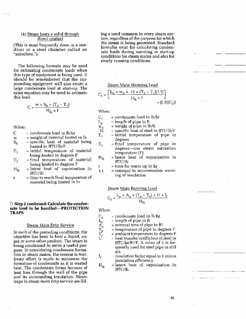
(4) Steam heats a solid through direct contact
(This is most frequently done in a ster- ilizer or a steel chamber called an “autoclave.”)
The following formula may be used for estimating condensate loads when this type of equipment is being used. It should be remembered that the sur- rounding equipment will also create a large condensate load at start-up. The same equation may be used to estimate this load.
w x Sh x (Tz - TI) C =
Hfg x t
When: C = condensate load in lb/hr W = weight of material heated in lb Sh = specific heat of material being
heated in BTU/lb/F TI = initial temperature of material
being heated in degrees F T, = final temperature of material
being heated in degrees F Hfg = latent heat of vaporization in
BTU/lb t = time to reach final temperature of
material being heated in hr
0 Step 2 continued: Calculate the conden- sate load to be handled-PROTECTION TRAPS
Steam Main Drip Service
In each of the preceding conditions, the objective has been to heat a liquid, air, gas or some other product. The steam is being condensed to serve a useful pur- pose. In considering condensate forma- tion in steam mains, the reverse is true. Every effort is made to minimize the formation of condensate as it is wasted heat. The condensate forms because of heat loss through the wall of the pipe and its surrounding insulation. Steam traps in steam main drip service are fill-
ing a need common to every steam sys- tem, regardless of the purpose for which the steam is being generated. Standard formulas exist for calculating conden- sate loads during warming or start-up conditions for steam mains and also for steady running conditions.
Steam Main Warming Load
1 L, x W, x -12 x (Tz - TI) ( I . l )
HF, x t c1= [
When: C, = condensate load in lbhr
= length of pipe in ft = weight of pipe in lb/ft wP
.12 = specific heat of steel in BTU/lb/F T, = initial temperature of pipe in
degrees T, =final temperature of pipe in
degrees-use steam saturation temperature (F)
= latent heat of vaporization in BTU/lb
= time for warm up in hr = constant to accommodate warm-
LP
Hfg
t 1.1
ing of insulation
Steam Main Running Load L, x A, x (T, - T,) x U x If c, =
Hfg
When:
C,
A, Tp Ta U
= condensate load in lb/hr = length of pipe in ft = external area of pipe in ft2 = temperature of pipe in degrees F = ambient temperature in degrees F = heat transfer coefficient of steel in
BTU/hr/ftz/F. A value of 3 is fre- quently used for steel pipe in still air.
= insulation factor equal to 1 minus insulation efficiency
= latent heat of vaporization in BTU/lb
L P
If
Hfg
41
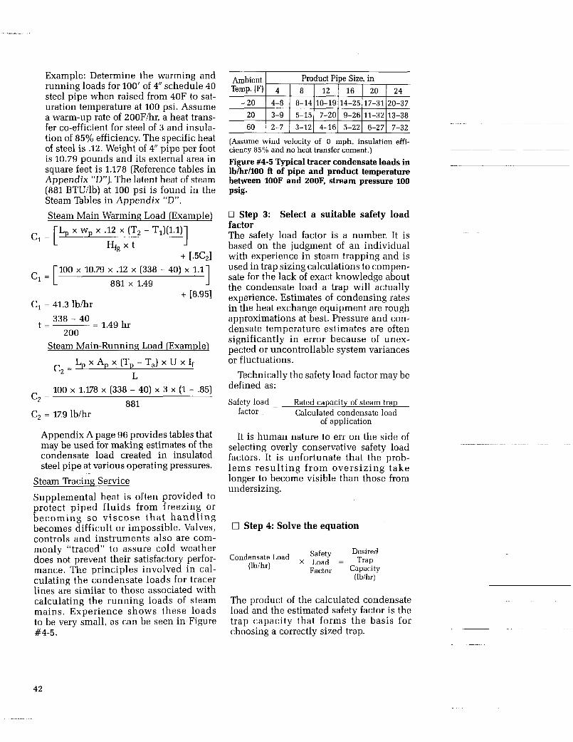
Example: Determine the warming and running loads for 100’ of 4” schedule 40 steel pipe when raised from 40F to sat- uration temperature at 100 psi. Assume a warm-up rate of 2OOF/hr, a heat trans- fer co-efficient for steel of 3 and insula- tion of 85% efficiency. The specific heat of steel is .12. Weight of 4“ pipe per foot is 10.79 pounds and its external area in square feet is 1.178 (Reference tables in Appendix “D”). The latent heat of steam (881 BTU/lb) at 100 psi is found in the Steam Tables in Appendix “D”. Steam Main Warming Load (Example)
Hfg x t - T1)(l*l)l + ~ 5 ~ 1
= [Lp wp *12 (T
= [ 1 100 x 10.79 x .12 x (338 - 40) x 1.1 881 x 1.49
+ [8.95] = 41.3 lb/hr
- - = 1.49 hr
Steam Main-Running Load [Example)
338 - 40
200
L, x A, x (T, - Ta) x U x If L
100 x 1.178 x (338 - 40) x 3 X (1 - .85)
c, =
- -
881 = 17.9 lb/hr
Appendix A page 96 provides tables that may be used for making estimates of the condensate load created in insulated steel pipe at various operating pressures.
Steam Tracing Service
Supplemental heat is often provided to protect piped fluids from freezing or becoming so viscose tha t handl ing becomes difficult or impossible. Valves, controls and instruments also are com- monly “traced” to assure cold weather does not prevent their satisfactory perfor- mance. The principles involved in cal- culating the condensate loads for tracer lines are similar to those associated with calculating the running loads of steam mains. Experience shows these loads to be very small, as can be seen in Figure #4-5.
(Assume wind velocity of 0 mph, insulation effi- ciency 85% and no heat transfer cement.) Figure #4-5 Typical tracer condensate loads in lb/hr/lOO ft of pipe and product temperature between l O O F and 200F, stream pressure 100 psig.
0 Step 3: Select a suitable safety load factor The safety load factor is a number. It is based on the judgment of an individual with experience in steam trapping and is used in trap sizing calculations to compen- sate for the lack of exact knowledge about the condensate load a trap will actually experience. Estimates of condensing rates in the heat exchange equipment are rough approximations at best. Pressure and con- densate temperature estimates are often significantly in error because of unex- pected or uncontrollable system variances or fluctuations.
Technically the safety load factor may be defined as:
Safety load - Rated capacity of steam trap factor - Calculated condensate load
of application
It is human nature to err on the side of selecting overly conservative safety load factors. It is unfortunate that the prob- lems result ing from oversizing take longer to become visible than those from undersizing.
0 Step 4: Solve the equation
Desired
Factor Capacity
Condensate Load Safety X Load = Trap
(lbihr) (lbihr)
The product of the calculated condensate load and the estimated safety factor is the trap capacity that forms the basis for choosing a correctly sized trap.
42
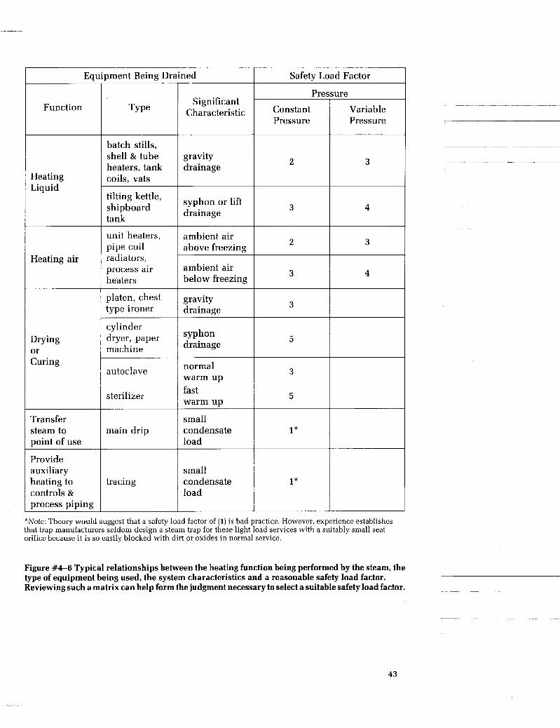
2 3
3 4
Jment Being Drained Safetv Load Factor
Pressure
Pressure Pressure
Significant Characteristic Function
batch stills, shell & tube heaters, tank coils, vats
gravity drainage
Heating Liquid
tilting kettle, shipboard tank
syphon or lift drainage
unit heaters, pipe coil radiators, process air heaters
ambient air above freezing 2 1 3
Heating air ambient air below freezing 3 l 4
platen, chest type ironer
gravity drainage 3 1
cylinder dryer, paper machine
syphon drainage
normal warm up fast warm up
Drying or Curing
5
autoclave
sterilizer
3 I I
5 l Transfer steam to point of use
small condensate load
main drip
Provide auxiliary heating to controls & process piping
small condensate load
tracing
*Note: Theory would suggest that a safety load factor of (1) is bad practice. However, experience establishes that trap manufacturers seldom design a steam trap for these light load services with a suitably small seat orifice because it is so easily blocked with dirt or oxides in normal service.
Figure #4-6 Typical relationships between the heating function being performed by the steam, the type of equipment being used, the system characteristics and a reasonable safety load factor. Reviewing such a matrix can help form the judgment necessary to select a suitable safety load factor.
43

DIFFERENTIAL PRESSURE, psi
Figure #4-7 Steam ’hap Capacity
0 Step 5: Choose a trap from the manu- facturer’s catalog Manufacturers generally provide their sizing capacity data in graphic form indi- cating the pressure and condensate tem- perature at which the rated capacity is stated to exist. As an example Figure #4-7 shows capacity curves typical of a bi- metallic trap having medium to heavy capacity.
Temperatures may sometimes be stated as “near steam temperature” or “within 10 degrees of saturation temperature”. These generalizations result from the fact that obtaining very accurate data is difficult even in a well equipped laboratory because of the difficulty in providing sufficient amounts of condensate at constant tem- perature. “Cold water” ratings are some- times stated because they are easiest to
obtain and because they give an indication of a trap’s capacity during a start-up situation.
Choose a trap with a capacity close to the calculated capacity for the pressure condi- tions and, of course, the proper sized end connections. Remember that while the cal- culated load can be carried out to the sec- ond decimal place, it is at best a rough approximation and that unexpected sys- tem variables may upset an otherwise good selection.
~~
Summary
Steam trap application is the process of first, sizing it to meet the specific conden- sate drainage requirements of a particular piece of equipment, and second, selecting a type of steam trap.
~
44

0 Steam trap sizing is the process of matching the condensate drainage require- ments of a particular piece of equipment with a steam trap’s condensate handling capacity at the pressure and temperature conditions to which it will be exposed.
Standard formulas exist to calculate the condensate loads that process traps will experience when serving any of the follow- ing four classes of equipment:
heats a liquid indirectly through a metal wall heats air or a gas indirectly through a metal wall heats a solid or slurry indirectly through a metal wall heats a solid through direct contact
Condensate loads experienced by pro- tection traps in tracer and steam main drip service can also be calculated by the use of standard formulas. These loads are gener- ally quite small and experience has shown that trap oversizing is a common problem.
Calculated condensate loads for process traps are normally increased by a safety load factor to compensate for system unknowns. Guidelines exist to aid in the selection of safety load factors. In general, the more that is known about the condi- tions associated with an application, the smaller will be the size of the factor.
0 Steam trap selection is the process of evaluating the relative advantages and dis- advantages associated with each of the basic trap technologies (thermostatic, ther- modynamic and mechanical), and match-
plant in which they will be used. These needs, or selection criteria, create a surprisingly long list:
Safety Efficiency Service Life Ease of checking Sensitivity to backpressure Resistance to freeze damage Dirt sensitivity Installation versatility Air venting Responsiveness to changing loads Resistance to shock, vibration and water
Predominant failure mode Discharge mode Condensate discharge temperature rela-
Magnitude of condensate sub-cooling Ease of maintenance Supplementing accessories or features Commercial considerations Selection of a thermostatic, thermo-
dynamic or a mechanical type trap for a particular service will necessarily depend on the criteria considered most important for satisfactory plant operation, as each trap technology has its unique advantages and disadvantages.
- ~~-~ ~ -~~
ing them with the needs or criteria of the -_
~ ~~ -~
hammer
tive to saturation curve
45


CHAPTER 5
PRINCIPLES OF STEAM TRAP INSTALLATION
Introduction A steam trap that fails to perform as expected is not necessarily faulty. Often “trap problems” are directly traceable to “piping system problems”. There are gen- eral piping system practices that must be followed if certain basic steam trapping problems are to be avoided. While some
pieces of heat exchange equipment have rather special piping requirements to achieve good trap performance, most do not. This chapter addresses the generalized rules for good piping practice and proper steam trap installation. Recommendations for trapping specific pieces of equipment are described in Appendix “A”.
47

A Review Of The Problems Affecting Steam n a p Performance “Good practice” evolves as knowledge is gained about the cause of problems and the techniques that are developed to avoid their repetition in the future. As back- ground to a consideration of steam trap installation principles, it is helpful to review the most common problems associ- ated with trap performance:
Problem Comment 0 Water hammer
0 Freeze-ups
0 Dirt
0 Air binding
0 Steam binding
0 Backpressure
0 Corrosion
Slugs of water hurtling through a piping system not only damage steam traps, but also other valuable equipment including the pip- ing system itself. Good piping practices promote good drainage and prevent the accumulation of water that makes water hammer possible. A shutdown in freezing conditions of a system that drains poorly, for whatever reason, is an invitation to trouble. In extremely cold conditions poorly insulated condensate return systems can freeze. Even if equipment is not damaged by ice, seldom the case, start-ups become extremely tedious because ice blockages prevent the cir- culation of steam necessary to bring the system up to temperature. Valuable production time is lost. By their nature steam traps generally have small passages that are subject to obstruction. Corrosion products and pipeline trash are the usual culprits. A clogged steam trap means trouble because it is no longer able to protect or drain the equipment it was meant to serve. Dirt pockets and strainers help to protect the trap. At startup time steam systems can be full of air. Some mechanical and thermodynamic traps have difficulty differentiating between steam and air. When such traps restrict the proper venting of air and delay the heating up of the system, they are considered to be “air binding.” Thermostatic air vents and thermostatic traps are com- monly used to improve air venting. Certain applications, piping configurations and steam trap types tend to create conditions in which steam at the trap keeps it closed, thereby preventing condensate which has formed upstream of the trap from being drained. Small levels of backpressure typical of a properly designed conden- sate return system are not generally a problem. It is the elevated levels of backpressure found in the inadequate return system that creates drainage problems. Corrosion is best controlled by proper boiler water treatment but
increases the potential for corrosion problems. any piping arrangements that interfere with good drainage ~ ~~
48

Branch Line
Overhead Return Line r i
--A+-- c,,,,,,3 I I I I
Check $7 L:A
Steam Main
Strainer Trap Union Tee Drip Trap
1
Dirt Pocket Blow
Down Valve
Return Line
Figure #5-1 A vp ica l Steam n a p Installation
The Steam ’hap Station-Some Basics Figure #5-1 shows a typical steam trap installation in a closed condensate return system. Several of its features will apply to any installation, specifically: 0 Strainers with blow down valves. Dirt is the enemy and unless a steam trap has an integral strainer, as many now do, it should have a strainer installed immediately upstream. The blow down valve which per- mits easy cleaning of the strainer screen often sees service as a useful diagnostic tool when a system or piece of equipment is slow to heat up. 0 Test “T” Regular verification that a steam trap is functioning properly is com- mon practice in all well maintained plants. Chapter VI, Steam Trap Maintenance, has a section on steam trap checking that describes the usefulness of a test “T” for verifying proper performance of a trap dis- charging into a closed return system. 0 Isolation valves: Isolation valves are necessary to permit the inevitable repair or replacement that all steam traps ultimately require. They are also required when using the test “T”. Valves should be fully ported -such as ball or gate valves-to minimize pressure drops that cause condensate flashing or raise backpressures.
Steam Trap Location-The Inlet Piping & Outlet Piping Steam traps should be installed one or two feet below the outlet of the equipment being served with the inlet piping sloping towards the trap to facilitate gravity drainage. A drip or dirt leg that is the same size pipe as the equipment drain connec- tion will help provide clean condensate and also serve as a condensate collecting resevoir. Pipe and fittings ahead of the trap should be equal to or one size larger than the trap to reduce the potential for the for- mation of flow interrupting flash steam. Discharge piping should be amply sized to accommodate flash steam and minimize back pressure. For short discharge lines use pipe equal to trap size; for longer lines use one pipe size larger.
When it is not possible to install a trap below the low point of the equipment being drained, a lift fitting or water seal is necessary. This may take the form of either a “U” shaped lift fitting or a small pipe or tube within the larger coil (See Figure
Without such an arrangement steam is able to reach the trap and keep it closed (steam binding) before the coils have been ade- quately drained. The t rap should be located below the high point of the loop
#5-2). ~
~
49

~~ ~~
Steam Line
n
Figure #5-2 A Lift Fitting Application
going over the side of the tank. A check valve is installed just ahead of the trap to prevent back flow into the coil.
The Steam Distribution System- Drainage & Trapping Good drainage of steam mains and branch lines is mandatory. A piping system that sags or otherwise allows pockets of con- densate to form, creates the conditions that cause water hammer and its associated damage. Such systems when shut down in freezing climates experience additional problems because of unwanted ice forma- tion. All natural drainage points and low points in a steam line or main require a steam trap and, in fact, steam main drip service is the most common trap applica- tion. Where long pipe runs exist without natural drainage points, they need to be created in the form of drip pockets at inter- vals of approximately 300 feet. Drip pockets should be the same diameter as the main or branch line as this helps prevent condensate from being carried past the pocket by high velocity steam. Drip pockets and drip traps should be placed upstream of temperature control, pressure reducing, and stop valves to prevent damage and assure dry steam supply to equipment. Drip traps are also required at expansion joints and loops and the termi- nal ends of steam mains.
The steam main itself should have a
slope of about one inch in twenty feet to facilitate condensate drainage by gravity.
Steam supply lines should always be tapped off the top of the steam main. This helps deliver dry steam to the equipment (See Figure #5-1).
Steam Separators Separators perform a job that steam traps cannot do. Steam traps drain condensate that has collected at a drainage point. Steam separators (or steam dryers) remove water droplets that are entrained in the steam flow. They are installed in the steam main immediately down-stream of the boiler, to improve the quality of steam going into the distribution system, or immediately ahead of equipment that requires especially dry steam. Steam sepa- rators, in turn, are drained by a steam trap.
The Condensate Return System The primary purpose of a condensate return system is to save the expense of con- tinually upgrading water to a quality suit- able for good boiler performance and to recover heat energy still in the condensate,
In addition, condensate return systems afford the opportunity to use flash steam in progressively lower pressure heating sys- tems. Condensate return is discussed in detail in Chapter 7.
thus improving overall system efficiency. ~~
50

I High Pressure Low pressure flash steam ~ Condensate from traps
H-P flash tank
Diip traps
Atmospheric vent
Low pressure condensate from traps
L -
Carefully size and select
condensate pumps and controls
Atmospheric receiver
4 \ To Boiler-feed system f
Condensate Pump
Figure #5-3 A condensate return system showing the collection & use of low pressure flash steam
51

Steam in
t Control Valve 8
I 6 ft
Sufficient Length to Prevent Coil Corrosion and/or Freezing
w-
1 ; Psi ondensate
Return
;: !!:A Creates 3 psi
Pipe Flooded With Condensate
3 psi + 5 psi = 8 psi
Total Back Pressure
I Figure #5-4 Estimating backpressure when discharging to an overhead return
While the benefits of a return system sig- nificantly outweigh the problems associ- ated with it, such a system does allow the formation of a back pressure against which steam traps must discharge. Back pressure at moderate levels is not a problem but at levels of 50% or more of inlet pressure, it can adversely affect the performance of bimetallic and thermodynamic traps. The discharge temperature of bimetallic traps become extremely suppressed, creating significant condensate backup. Ther- modynamic traps become less efficient- i.e., begin to pass steam.
The significance of these comments is simply to establish that piping factors which increase the backpressure against which a trap must discharge, also increase the potential for unexpected trapping problems.
A common cause of excessively elevated backpressures in a return system is the plant expansion that increased the number
of steam traps discharging into the system without also having increased its size to accommodate the additional flash steam.
Condensate Lifting When the condensate discharged from a steam trap must be raised to a collecting manifold or header, it is necessary to assure that the discharge pressure at the trap is sufficient to overcome the vertical lift plus the pressure in the overhead return line. If this is not the case, reverse flow will take place. Every foot of elevation follow- ing a trap will add % psi to the back- pressure the trap experiences. It is impor- tant to assure in these applications that total backpressure does not exceed the allowable limits of the particular type of trap selected. Figure #5-4 shows an exam- ple of the arithmetic used in estimating backpressure when a trap is discharging to an overhead return line. Note that pipe, valves and fitting pressure losses will also contribute to the backpressure.
52
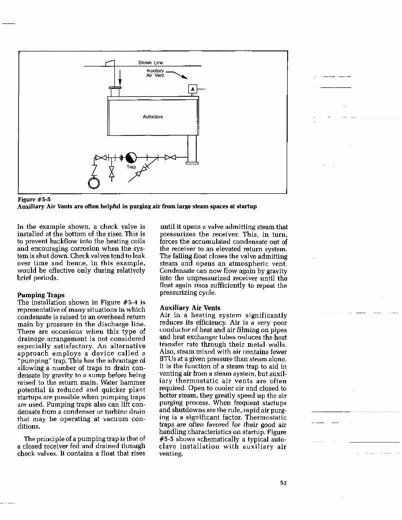
Steam Line
Auxiliary Air Vent \4
I
Figure #5-5 Auxiliary Air Vents are often helpful in purging air from large steam spaces at startup
In the example shown, a check valve is installed at the bottom of the riser. This is to prevent backflow into the heating coils and encouraging corrosion when the sys- tem is shut down. Check valves tend to leak over time and hence, in this example, would be effective only during relatively brief periods.
Pumping Traps The installation shown in Figure #5-4 is representative of many situations in which condensate is raised to an overhead return main by pressure in the discharge line. There are occasions when this type of drainage arrangement is not considered especially satisfactory. An alternative approach employs a device called a “pumping” trap. This has the advantage of allowing a number of traps to drain con- densate by gravity to a sump before being raised to the return main. Water hammer potential is reduced and quicker plant startups are possible when pumping traps are used. Pumping traps also can lift con- densate from a condenser or turbine drain that may be operating at vacuum con- ditions.
The principle of a pumping trap is that of a closed receiver fed and drained through check valves. It contains a float that rises
until it opens a valve admitting steam that pressurizes the receiver. This, in turn, forces the accumulated condensate out of the receiver to an elevated return system. The falling float closes the valve admitting steam and opens an atmospheric vent. Condensate can now flow again by gravity into the unpressurized receiver until the float again rises sufficiently to repeat the pressurizing cycle.
Auxiliary Air Vents Air in a heating system significantly reduces its efficiency. Air is a very poor conductor of heat and air filming on pipes and heat exchanger tubes reduces the heat transfer rate through their metal walls. Also, steam mixed with air contains fewer BTUs at a given pressure than steam alone. It is the function of a steam trap to aid in venting air from a steam system, but auxil- iary thermostatic air vents are often required. Open to cooler air and closed to hotter steam, they greatly speed up the air purging process. When frequent startups and shutdowns are the rule, rapid air purg- ing is a significant factor. Thermostatic traps are often favored for their good air handling characteristics on startup. Figure #5-5 shows schematically a typical auto- clave installation with auxiliary air venting.
~~
53

Steam in -+
Condensate Return I
Min. as recommended by coil mfgr. up to 3 ft. for modulating steam and freezing air temperature
Figure #5-6 A Vacuum Breaker aids in the drainage of condensate when a steam system is shut down
Vacuum Breakers When a closed and pressurized steam sys- tem is allowed to cool down, it is not just the temperature that drops. The pressure in the system will decay to a vacuum unless some mechanism permits the entrance of air, thus allowing the system to achieve atmospheric pressure. Such a mechanism is called a vacuum breaker. It is essentially a check valve, closed to internal pressure, but open when that internal pressure becomes less than atmospheric. Figure #5-6 shows schematically the installation of a vacuum breaker on an air heating coil. If the upper shutoff valve is closed while the heating unit is in operation, conden- sate will not be able to drain out of the unit. As it cools, it is possible for condensate that has drained, into the return system earlier, to be drawn back into the unit unless a vacuum breaker functions to per- mit air to enter the system.
Summary Performance problems with steam traps are often directly traceable to the piping arrangements used to install them. Experi- ence continues to justify the wisdom of knowing and following good piping practice.
Ideally, condensate should be able to drain freely to (and from) a steam trap by gravity. Line restrictions which may pro- duce elevated backpressures or lead to con- densate flashing, should be avoided. Such restrictions may result from the use of undersized valving or excessive pipeline size reductions. When condensate must be raised to reach a trap or an elevated return main, care should be exercised so that steam binding or excessive backpressures do not occur.
Steam traps should be installed so that performance checks and maintenance activities can be easily performed. Prop- erly sized strainers with a suitable blow down valve are an easily justified steam trap protection device. Air vents, vacuum breakers and check valves may be required to solve specific drainage or flow problems which otherwise would adversely affect a steam trap’s performance.
The removal of condensate from a steam system cannot be considered as an after- thought. The absence of problems associ- ated with water hammer, corrosion, dirt and freeze-ups has been the result of care- ful planning and conscious effort to avoid the root causes of these problems.
~
~
54

I " _I__
CHAPTER 6
STEAM TRAP MAINTENANCE AND TROUBLESHOOTING
Introduction Steam traps must be selected, sized and installed carefully if good system efficien- cies are to be achieved. By themselves, however, these factors will not assure an efficient system. In the long run, regular maintenance of the selected traps will be the significant factor in system efficiency because in time all steam traps fail. In spite of the certainty of failure and the high cost consequences that can result, really good trap maintenance programs seem to be the exception rather than the rule. This may be because traps are relatively inexpensive devices and it may be wrongly considered that they perform a relatively inconsequen- tial task.
The equipment that traps protect is often large and expensive. Its damage or reduced productivity can be very costly. When a steam trap fails in the closed position, con- densate will back up into a heat exchanger. This can spoil the product at the worst or simply reduce heat exchanger utility at the best. A trap that has failed closed in other circumstances, such as in a freezing environment, can readily lead to lines blocked or broken by ice.
Alternatively, when a steam trap fails in its open position, it usually damages noth- ing. It simply allows steam to flow through a system at much higher rates than is nec- essary for the heating job to be performed.
It reduces system efficiency in the same manner as any other steam leak. While it is generally considered more desirable for a trap to fail in the open rather than the closed position, either can have significant adverse cost consequences.
The very high cost of generating steam, and then failing to use it properly, is begin- ning to gain the attention of plant manag- ers. Also, recognition is developing that a good steam trap maintenance program is not a questionable expense but a source of significant cost savings both in fuel costs and in higher equipment utilization. Any plant seriously interested in reducing its energy costs must develop a systematic approach to maintaining its steam traps in proper operating condition.
Maintenance Programs Maintenance programs will necessarily differ among plants having five, five hundred or fifteen thousand steam traps. Nevertheless, their objective will be funda- mentally the same.
In larger plants having one thousand or more traps, individuals with the full-time assignment of checking and reporting the performance of s team traps are increasingly common. Smaller plants may not have a full-time specialist, but some are attempting to have an individual who is especially knowledgeable about steam
55
traps and steam-trapping practice. Regard- less of the size of the plant, a common problem exists for every steam trap user: the difficulty of determining if a trap is working properly. While sometimes it is a relatively easy matter, frequently it is diffi- cult, speculative and uncertain. Spe- cialized equipment exists to help the steam trap checker and a great deal has been writ- ten listing logical progressions of ques- tions and tests to establish if a trap is performing properly for its given condi- tions. However, conclusive answers to some of these questions are frequently not easy to supply.
To date a good bit of experience, judg- ment and art are still necessary to identify malfunctioning traps-especially if they are discharging into a closed return system.
The Essentials of a Successful Maintenance Program Successful maintenance programs of the larger users of steam traps tend to have certain common elements. A review of these elements can be useful to mainte- nance managers in the plants having small as well as large trap populations. They are: 0 A committed member of Plant Manage- ment who understands the high financial payback associated with an efficient and well-maintained steam trapping system. 0 A valid cost analysis developed over a meaningful period of time which has shown the dollar savings in energy costs associated with a specialized pilot mainte- nance program for steam traps. Often initi- ated in a single portion of the plant, these pilot programs, allow product produced to be correlated with steam consumed both before and after the start of a specialized steam trap maintenance activity. 0 A full-time steam trap maintenance crew, including a diagnostic specialist, in addition to the personnel who repair or replace defective traps. 13 A set of steam trapping standards whidh recommend a correct piping configuration and trap type for the various trap applica- tions in the plant. Efforts generally have been made to standardize on as few trap types as practical.
0 A complete, but easily kept, set of main- tenance records including simple maps identifying the location of every trap in each area of the plant. Survey sheets are employed that list (1) an identifying num- ber for every trap location in a given area; (2) the equipment being drained; (3) the operating pressure; (4) the trap type suit- able for the application; (51 and a place to record trap condition at the time of a survey. 0 Numbering and tagging every trap loca- tion is essential for a successful mainte- nance program. The written records of the condition of each trap at the time of inspec- tion, are also essential so that inspection frequencies can be logically established. These records also provide opportunities for a wide range of performance analyses and comparisons between trap types should there be evidence that additional cost savings can be obtained by seeking absolutely optimum performance.
The Importance Of Trapping Standards When experience has shown that the requirements of a certain application are well satisfied by a specific type of trap and piping configuration, it makes sense to establish a trapping standard that will apply to all similar applications. When this standardizing process is expanded to cover all trap applications in a plant, it produces important benefits. The steam trap maintenance activity is greatly sim- plified. The variety of traps in use is reduced and their proper performance becomes better understood by mainte- nance personnel. Traps that have reached the end of their normal service life are repaired. Misapplied traps are more easily recognized and are replaced, rather than mistakenly reinstalled. Repeatedly, the experience of steam trap users who make the effort to standardize their steam trap- ping practices is an improvement insystem reliability and efficiency.
Establishing 'happing Standards A plant that has become convinced it can benefit from the establishment of steam trapping standards my be tempted to sim- ply adopt standards which have been suc- cessfully used elsewhere. This is probably unwise. A chemical plant, a refinery, a
56

papermill or a food processing plant rea- sonably can be expected to have different trapping standards. The manner in which these plants operate will be different and their exposure to freezing weather can vary-both factors will strongly influence the standards that should be adopted. While good piping and installation prac- tices are the same, regardless of industry or climate, the specific trapping require- ments of individual plants should be recognized.
Getting Started With Trapping Standards The initiation and development of trap- ping standards for an organization may occur in a wide variety of ways, but ulti- mately someone has to wrestle with some basic questions. Typically: 1. How should steam trap applications be
classified so that standardization can reasonably take place?
2. What are the most important criteria by which steam trap performance should be judged?
Classification Of Steam Trap Applications Steam trap applications are classified in at least two major ways: 1. Type of equipment being drained. For
example; steam mains, drying cylin- ders, heat exchangers, storage tanks, vulcanizing presses, tracing lines.
2. By generic conditions as defined by pressure and condensate load. These can be represented by a simple matrix such as Figure #6-1 or one that is more refined, Figure #4-2.
If the operating conditions-i.e., pres- sure and condensate loads-are quite uni- form for each of the specific types of equipment in a plant, then classification by equipment being served may be quite suitable. Often this is not the case, as there may be steam mains at 100 psi and others at, say 500 psi, or small heat exchangers having condensate loads of 1000 psi while others approach 10,000 psi. Differences of these magnitudes almost inevitably lead to different standards recommendations. Generic classification of operating condi- tions by its very nature tends to be more
\ Load IBelowl Between
Pres.
Below 100 psi
Between 100 & 300 psi
Between 300 81 600 psi
Between 1o0o&10000
lblhr
Figure #6-1 Matrix format that can be helpful in establishing plant-wide steam trap standards. Each quadrant block should reference the preferred type of trap for the stated conditions.
widely applicable. Sometimes it is por- trayed in a graphic manner as shown in Figure #6-2.
'Rap Evaluation Criteria A list of the criteria useful in evaluating the suitability of a steam trap for a particular application can be quite long. Chapter #4, Principles of Steam Trap Application, dis- cusses these criteria at length and Figure #4-3 shows such a list. Selecting a steam trap type (thermostatic, thermodynamic or mechanical) as the standard for a particu- lar application in a plant requires making decisions about the inherent advantages and disadvantages associated with each type. Chapter #3, Operating Principles of Steam Traps, describes these advantages and disadvantages. Obviously, the deci- sion to standardize on a particular trap type for a certain application should be made with great care and after evaluation of all relevant factors because, by defini- tion and intent, a standard will be used over and over again.
Steam n a p Checking Regardless of the care that has been spent in classifying a plant's steam trap installa- tions, and the thoroughness with which
57
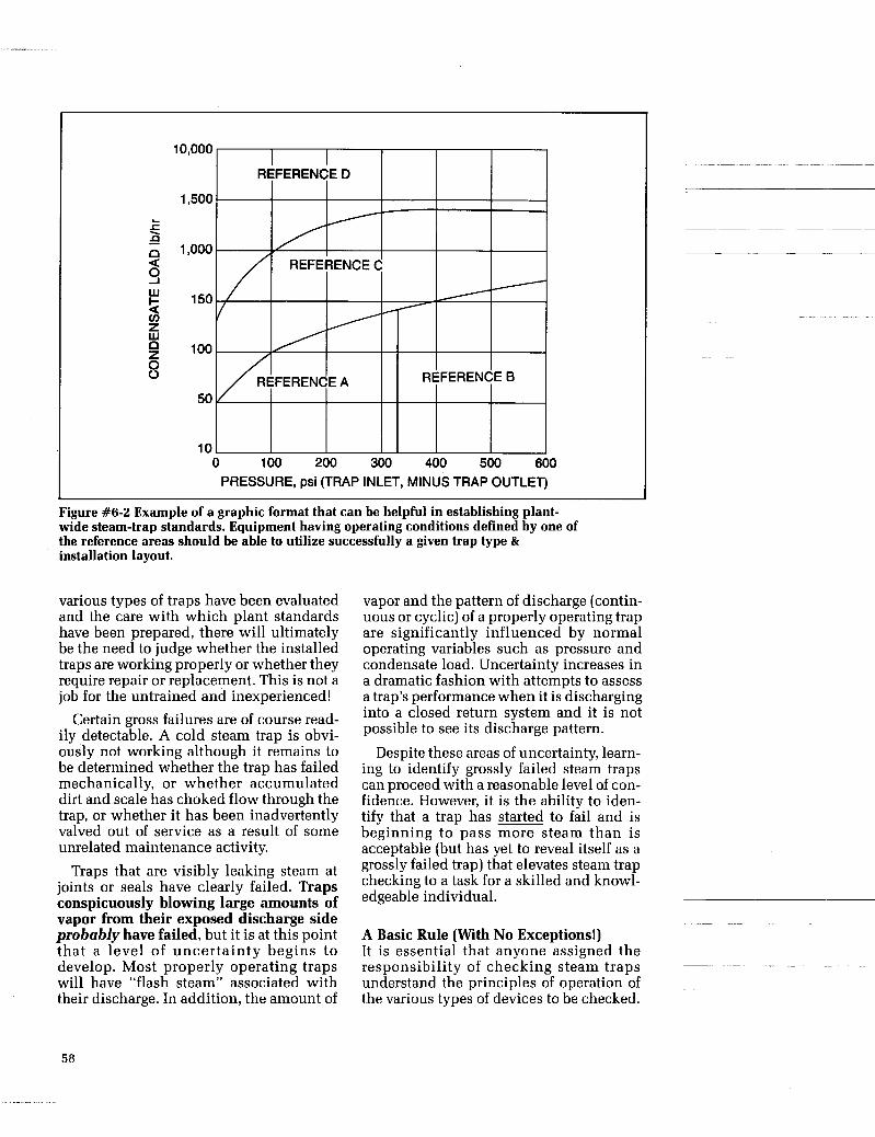
10,000
,500
,000
150
100
50
10
PRESSURE, psi (TRAP INLET, MINUS TRAP OUTLET)
Figure #6-2 Example of a graphic format that can be helpful in establishing plant- wide steam-trap standards. Equipment having operating conditions defined by one of the reference areas should be able to utilize successfully a given trap type & installation layout.
various types of traps have been evaluated and the care with which plant standards have been prepared, there will ultimately be the need to judge whether the installed traps are working properly or whether they require repair or replacement. This is not a job for the untrained and inexperienced!
Certain gross failures are of course read- ily detectable. A cold steam trap is obvi- ously not working although it remains to be determined whether the trap has failed mechanically, or whether accumulated dirt and scale has choked flow through the trap, or whether it has been inadvertently valved out of service as a result of some unrelated maintenance activity.
Traps that are visibly leaking steam at joints or seals have clearly failed. Traps conspicuously blowing large amounts of vapor from their exposed discharge side probably have failed, but it is at this point that a level of uncertainty begins to develop. Most properly operating traps will have “flash steam” associated with their discharge. In addition, the amount of
vapor and the pattern of discharge (contin- uous or cyclic) of a properly operating trap are significantly influenced by normal operating variables such as pressure and condensate load. Uncertainty increases in a dramatic fashion with attempts to assess a trap’s performance when it is discharging into a closed return system and it is not possible to see its discharge pattern.
Despite these areas of uncertainty, learn- ing to identify grossly failed steam traps can proceed with a reasonable level of con- fidence. However, it is the ability to iden- tify that a trap has started to fail and is beginning to pass more steam than is acceptable (but has yet to reveal itself as a grossly failed trap) that elevates steam trap checking to a task for a skilled and knowl- edgeable individual.
A Basic Rule (With No Exceptions!) It is essential that anyone assigned the responsibility of checking steam traps understand the principles of operation of the various types of devices to be checked.
58
It is no more realistic to attempt to diag- nose the performance of a steam trap with- out first knowing its principle of operation than it would be to diagnose the perfor- mance of an internal combustion engine without knowing the difference between a diesel, a turbine, or a gasoline engine.
Seat and valve leakage generally results from pipeline dirt becoming caught between their mating surfaces. Small man- ufacturing imperfections relating to sur- face finishes or proper alignment can also shorten trap life.
Chapter # 3 , Operating Principles of Steam Traps describes how each of the various trap technologies work. Ther- mostatic traps (bimetallic, filled bellows, diaphragm capsule and constant tempera- ture-capsule) all have different perfor- mance characteristics. Thermodynamic traps (disc, piston, lever) have different performance characteristics between themselves and also from the thermostatic models. Mechanical traps (bucket and float) have performance characteristics that differ from each other and yet are simi- lar to some of the other trap types.
0 Pipeline dirt, oxides, scale and pipe joint sealants are the enemy of all types of steam traps. Some trap types are more for- giving than others, but all have their limits. A trap which has the appearance of having failed closed because of dirt can often be restored to useful service with a simple cleaning.
A trap leaking steam because of dirt between the valve and seat probably should be replaced or repaired with new components. The likelihood of permanent damage having occurred because of the dirt is high.
acteristic associated with some trap types can be altered significantly under certain operating conditions. This phenomenon is generally associated with very high or low condensate loads (relative to the trap’s capacity) or with very high or low pressure differentials across the trap (relative to its pressure rating).
Fundamentals Concerning Trap Failures 0 Most types of traps will fail open so that they leak steam. Some types of traps fail closed so that they pass neither condensate nor steam, and some types of traps will fail unpredictably in either an open or closed mode.
Fundamentals Concerning Trap Checking Techniques
Checking a steam trap is the process of observing its performance and comparing it with the performance characteristics that one has learned are typical for a healthy trap of the same type. If the performances are similar, the trap may be judged to be O.K. If there are differences, it can be con- cluded that either the trap is faulty or the system in which the trap is installed has a problem.
There are three basic techniques used in observing the performance characteristics of a steam trap. They are:
types Of steam traps can appear to
or problem in the system in which they are
0 Sight-visually observe the discharge
0 Sound-listen to the functioning of the pattern;
valve mechanism and the flow of fluid through the seat; ,, Temperature-determine the trap,s
have failed because of some shortcoming
installed. While this fact must always be kept in mind it does not become a signifi- cant issue unless the steam system has been neglected. temperature. 0 The most common failure for all tvms of .,I
steam traps is erosion of the seat and valve sealing faces. This keeps the trap from clos- ing tightly. Once a small leak starts in a pressurized steam system, it becomes a large and expensive leak in a short time.
Each of the checking techniques has its limitations and seldom can a conclusive opinion be reached on the basis of a single type of observation. Experienced steam trap checkers invariably try to use all three
59

techniques. Some will use more expensive checking equipment than others in this checking process, but the quality of their results does not seem to vary much.
Sight Watching the discharge pattern of a steam trap is probably the most reliable method of determining whether it is working prop- erly. Unfortunately, many traps discharge into closed condensate return systems without test “T”s and the discharge pattern is not visible. Under these conditions trap performance appraisal is limited to sound and temperature monitoring.
The fundamental limitation to observing the discharge pattern of a steam trap in order to assess its health is that hot conden- sate discharging to atmosphere flashes into steam. The observer then has to decide whether the clouds of vapor being wit- nessed are the result of leaking steam or the normally expected flash steam. An experi- enced eye begins to distinguish the lazier action and white appearance of flash steam from the more transparent jet-like dis- charge of live steam that can be seen right at the trap’s outlet. The best clues come with watching a steam trap that has a normal crisp off/on cycle, such as a disc or bucket trap. If the discharge vapor has any velocity during the closed period of the trap’s cycle, it can be reasonably assumed that it is leak- ing steam and should be replaced.
While most thermostatic traps can have a cyclic mode discharge, it tends to be slower and less definite than either the disc or bucket types. Thermostatic traps, especially bimetallic traps, can also have a continuous discharge pattern. Float traps that are designed for continuous modulat- ing drainage are harder to diagnose, especially in the early stages of failure.
Steam trap mancfacturers recommend, and many users routinely install, a test “tee” and valving arrangement that will permit witnessing a trap’s discharge pat- tern in an otherwise closed condensate return system. The initial extra cost of this type of installation is handsomely repaid by the surer knowledge it produces con- cerning steam trapping efficiency.
Sound Listening to the sound of a steam trap func- tioning with the bit of a long handled screwdriver (held against the trap and its handle pressed against an ear) can provide important information as to whether it is doing its job properly. Because of the high background noise that often surrounds a steam trap, the screwdriver or industrial stethoscope is giving way to the ultrasonic listening device with earphones. These help to screen out the normal ambient background noise and permit more precise identification of a noise pattern in an indi- vidual trap.
The weakness of these devices, which is not overcome with the more expensive models, is that to hear a noise pattern is not necessarily the same thing as understand- ing what it means. Listening to a trap which is designed to have an open and closed cycle action can quickly reveal if the trap is operating in this manner. It can also reveal if there is any significant leak- age past the valve when it is in its closed position. But the value of listening to float traps or thermostatic traps operating in a modulating mode in an effort to determine if they are leaking steam is questionable. The noise patterns generated in the trap can be heard relatively easily. The problem is in the mind of the listener-“What do they mean?”
Temperature Every individual who checks steam trap performance employs some sort of tem- perature sensing means. A wet finger (obviously dangerous), a squirt bottle, a surface-contacting pyrometer, or an infrared sensor all have the same initial objective: Is this trap hot? If not, it can be deduced that little or nothing is flowing through it and the trap is not performing one of its major functions-draining con- densate. This does not necessarily mean that the trap has failed. It first must be determined if some obstruction-either up or downstream of the trap-has blocked flow in the pipe. Once that issue is resolved, it is logical to proceed with steps investigating the trap for blockage by pipeline dirt or failure of its internal mechanism.
60

When it has been determined that a steam trap is hot, the next question is whether it is as hot as it should be. Steam traps designed to discharge condensate very close to steam temperature such as disc, bucket or float traps will have a sur- face temperature about 5 to 10% below the temperature of steam in the system. Figure #6-3 shows typical pipeline surface tem- peratures.
Steam Temperature
(F) 250 298 338 366 388 460
Steam Pressure
(Psig)
Pipe Surface Temperature
Range (F)
238-225 283-268 32 1-304 348-329 369-349 437-414
15 5 0
100 150 200 450
Figure #6-3 Pipe Surface Temperature vs. Steam Pressures
Unfortunately, it does not follow that if temperatures are observed in this range that the trap is healthy. It only means it is doing half its job properly, i.e., draining hot condensate. It is difficult to determine
by temperature alone if a trap is leaking steam when it is designed to operate at
temperatures are much below the expected range, the trap can be suspected of backing up more condensate than normal.
at temperatures well below that of steam, such as some of the thermostatic types sim- ply reverse the generalities described above. If they measure hotter t han expected, they probably have failed and are leaking steam. If the temperatures are well below the steam temperatures in the sys- tem, these traps may be judged to be back- ing up condensates as they have been designed to do.
In general, there will be a significant dif- ference in temperatures between that observed upstream of a trap and that observed downstream. These temperatures will be directly related to the pressure in the system at the point of measurement. If the temperatures measured up and down- stream of a trap are the same, it can only be deduced that the pressure on either side of the trap is the same. As this is an abnormal condition, it can be concluded that a sys- tem problem exists that may or may not be caused by a faulty trap discharging into a common return. More analysis is necessary.
close to steam temperatures. If measured ~ ~~
Traps designed to discharge condensate ~~~~~~
Figure #6-4 Live Steam and Flash Steam
61

Equipment - Temperature Measuring . Sound Detection * Safety Glasses
Of Basic System Of Tkap Operation
Is It Hot?
Yes No
t t Is The System Shut Off,
Blocked With Air or Dirt? What 'Qpe of Trap?
Thermodynamic Thermostatic Mechanical Disc * Bellows Bucket Piston - Bimetal - Float
* Lever - Diaphragm Thermostatic
(wax cap ] * Constant Temp
Proceed To Section Describing Specific n a p Type I I Figure #6-5 Steam Trap Checking Decision Tree
The n a p Checking Decision Tree There is a logical progression of steps
leading to the decision that determines whether an installed steam trap is healthy enough to continue in service or whether it should be repaired or replaced. Because of the multiplicity of variables and the increasingly wide variety of trap types, this decision tree can be enormous. Outlined below is a progression of basic questions which illustrates only the major branches of the tree. It is suitable as a troubleshoot- ing starting point and entirely adequate for identifying the vast majority of failed traps.
In attempting to answer these basic ques- tions, it is assumed that visual, tempera- ture and listening techniques will d l be used. It is also assumed that the indi- viduals doing the checking will have cer- tain basic background information about: 1. the system i n w h i c h the t r ap is installed. Specifically, 0 the approximate pressure upstream and downstream of the trap;
0 that the overall system is stable-nei- ther starting up nor being shut down; 0 the trap application and its general characteristics 2. the basic operating principle of the trap and whether it can be expected to: 0 discharge condensate within about 10" of steam temperature a s most ther- modynamic and mechanical traps do or at much larger suppression temperatures as is characteristic of some of the thermosta- tic traps; 0 have a distinct off-on cycle typical of a thermodynamic (disc type) and mechan- ical (bucket) or have a modulating or con- tinuous flow typical of a mechanical (float) and some thermostatic traps which tend to throttle flow. Figure # 6 - 5 outlines the first major branches of the steam trap checking deci- sion tree. Successive branches associated with each trap type are presented on subse- quent pages.
~ ~~
62
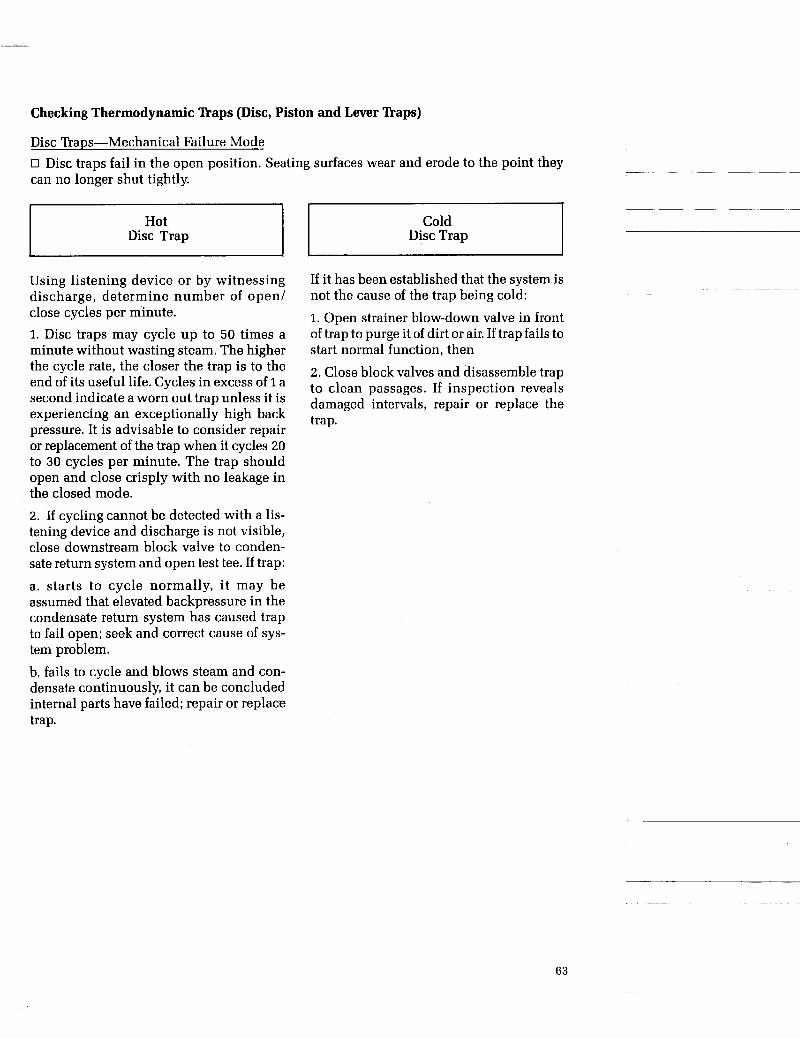
Checking Thermodynamic 'haps (Disc, Piston and Lever naps)
Disc Traps-Mechanical Failure Mode 0 Disc traps fail in the open position. Seating surfaces wear and erode to the point they can no longer shut tightly.
Hot Disc Trap
~~~~
Using listening device or by witnessing discharge, determine number of open/ close cycles per minute. 1. Disc traps may cycle up to 50 times a minute without wasting steam. The higher the cycle rate, the closer the trap is to the end of its useful life. Cycles in excess of 1 a second indicate a worn out trap unless it is experiencing an exceptionally high back pressure. It is advisable to consider repair or replacement of the trap when it cycles 20 to 30 cycles per minute. The trap should open and close crisply with no leakage in the closed mode. 2. If cycling cannot be detected with a lis- tening device and discharge is not visible, close downstream block valve to conden- sate return system and open test tee. If trap:
a. starts to cycle normally, it may be assumed that elevated backpressure in the condensate return system has caused trap to fail open; seek and correct cause of sys- tem problem. b. fails to cycle and blows steam and con- densate continuously, it can be concluded internal parts have failed; repair or replace trap.
Cold Disc Trap
If it has been established that the system is not the cause of the trap being cold:
1. Open strainer blow-down valve in front of trap to purge it of dirt or air. If trap fails to start normal function, then
2. Close block valves and disassemble trap to clean passages. If inspection reveals damaged intervals, repair or replace the trap.
63

Piston & Lever Trap-Mechanical Failure Mode
~
Piston and lever traps fail in the open position. Seating surfaces wear and erode so that ~- ~ ~~
trap can no longer close tightly.
~~- ~~~
Piston or Lever Trap Piston or Lever Trap
Follow same procedure described for checking disc traps. Note that these traps are designed with a control flow orifice. This small orifice will constantly dis- charge condensate between normal full open cycles of the main valve. If control flow discharge appears excessive, inspect trap valve seat for wear.
Follow same procedure described for checking disc traps. Note that these traps have good air handling characteristics and are not susceptible to air binding.
64

Checking Thermostatic n a p s (Bellows, Bimetallic, Diaphragm 81 Wax Capsule)
Bellows Trap-Mechanical Failure Modes 0 Manv bellows tram fail closed due to a ruptured bellows that allows the valve to be pressed closed against the seat. Some trap manufacturers provide a bellows that allows the valve to move to an open position if the bellows ruptures. 0 Bellows tram can also fail open due to wear and erosion of the valve and seat or extreme bellows distortion that prevents valve from contacting seat.
Bellows Trap Bellows Trap
Confirm that seat and valve are momen- tarily capable of being shut, and that bel- lows is “alive” by: 1. Partially opening strainer blow-down valve in front of trap to drain condensate from line and expose trap to dry steam.
2. Witness shut-off of trap discharge by means of downstream test tee. 3. Failure to see tight shut-off confirms trap needs repair or replacement.
Using a listening device or temperature sensor can assist in confirming that bel- lows is “alive” and cycling if test tee is not available to witness trap’s response to dry steam. If cycling is not evident, it may be induced momentarily by shutting off upstream block valve for a minute or two to artificially backup condensate. Releasing condensate will cause trap to open briefly, before closing again, thus demonstrating that bellows is “alive”.
Listening devices can occasionally detect steam leakage if seat and valve are suffi- ciently worn to prevent tight shutoff. If tight shut-off is still doubtful, close block valves, disassemble trap and inspect bel- lows and seat for erosion.
If it has been established that the system is pressurized and is not the cause of trap being cold: I. Close block valves and disassemble trap to inspect it for failed bellows or need to clean flow passages of dirt.
2. Repair or replace trap if bellows is rup- tured or spongy.
65
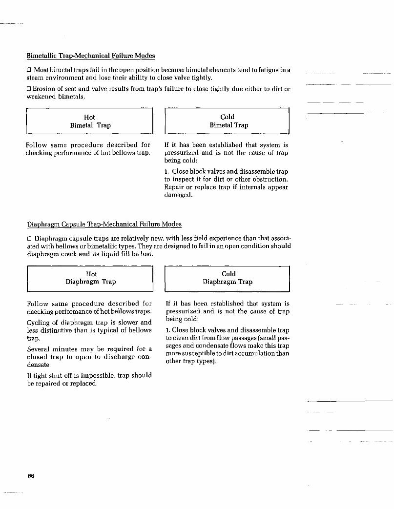
Bimetallic Trap-Mechanical Failure Modes
0 Most bimetal traps fail in the open position because bimetal elements tend to fatigue in a steam environment and lose their ability to close valve tightly.
0 Erosion of seat and valve results from trap’s failure to close tightly due either to dirt or weakened bimetals. ss Bimetal Trap Bimetal Trap
Follow same procedure described for If it has been established that system is checking performance of hot bellows trap. pressurized and is not the cause of trap
being cold:
1. Close block valves and disassemble trap to inspect it for dirt or other obstruction. Repair or replace trap if internals appear damaged.
-
~~ ~ ~~~~
Diaphragm Capsule Trap-Mechanical Failure Modes
0 Diaphragm capsule traps are relatively new, with less field experience than that associ- ated with bellows or bimetallic types. They are designed to fail in an open condition should diaphragm crack and its liquid fill be lost.
Hot Diaphragm Trap
Cold Diaphragm Trap
Follow same procedure described for checking performance of hot bellows traps.
Cycling of diaphragm trap is slower and less distinctive than is typical of bellows trap. Several minutes may be required for a closed trap to open to discharge con- densate.
If tight shut-off is impossible, trap should be repaired or replaced.
If it has been established that system is pressurized and is not the cause of trap being cold:
1. Close block valves and disassemble trap to clean dirt from flow passages (small pas- sages and condensate flows make this trap more susceptible to dirt accumulation than other trap types).
66
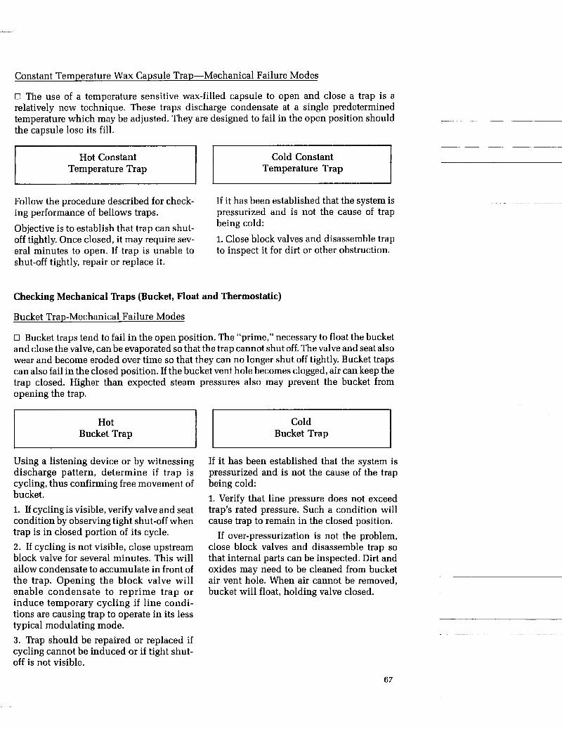
Constant Temperature Wax Capsule Trap-Mechanical Failure Modes
0 The use of a temperature sensitive wax-filled capsule to open and close a trap is a relatively new technique. These traps discharge condensate at a single predetermined temperature which may be adjusted. They are designed to fail in the open position should the capsule lose its fill.
Temperature Trap Temperature Trap
Follow the procedure described for check- ing performance of bellows traps.
Objective is to establish that trap can shut- off tightly. Once closed, it may require sev- era1 minutes to open. If trap is unable to shut-off tightly, repair or replace it.
If it has been established that the system is pressurized and is not the cause of trap being cold: 1. Close block valves and disassemble trap to inspect it for dirt or other obstruction.
Checking Mechanical naps (Bucket, Float and Thermostatic)
Bucket Trap-Mechanical Failure Modes
0 Bucket traps tend to fail in the open position. The “prime,” necessary to float the bucket and close the valve, can be evaporated so that the trap cannot shut off. The valve and seat also wear and become eroded over time so that they can no longer shut off tightly. Bucket traps can also fail in the closed position. If the bucket vent hole becomes clogged, air can keep the trap closed. Higher than expected steam pressures also may prevent the bucket from opening the trap.
Hot Bucket Trap
Using a listening device or by witnessing discharge pattern, determine if trap is cycling, thus confirming free movement of bucket. 1. If cycling is visible, verify valve and seat condition by observing tight shut-off when trap is in closed portion of its cycle. 2. If cycling is not visible, close upstream block valve for several minutes. This will allow condensate to accumulate in front of the trap. Opening the block valve will enable condensate to reprime trap or induce temporary cycling if line condi- tions are causing trap to operate in its less typical modulating mode. 3. Trap should be repaired or replaced if cycling cannot be induced or if tight shut- off is not visible.
Cld Bucket Trap
If it has been established that the system is pressurized and is not the cause of the trap being cold: 1. Verify that line pressure does not exceed trap’s rated pressure. Such a condition will cause trap to remain in the closed position.
If over-pressurization is not the problem, close block valves and disassemble trap so that internal parts can be inspected. Dirt and oxides may need to be cleaned from bucket air vent hole. When air cannot be removed, bucket will float, holding valve closed.
67

Float & Thermostatic Trap-Mechanical Failure Modes
0 Float and thermostatic traps can fail in either a closed or an open position. They fail closed if the float is ruptured by water hammer and can no longer rise to open the valve. They also fail closed if the thermostatic element fails and air cannot be vented from trap.
They fail open when the main valve and seat or thermostatic air vent valve and seat are worn or eroded so that they leak steam.
~~~~~~ ~~
Hot Float and Thermostatic Trap
~
Because trap is designed to drain conden- sate continuously, verification that valve and seat of trap and air vent are not leaking steam is very difficult unless leakage is very large.
1. Examine trap discharge pattern for evi- dence of excessive vapor-i.e., steam leakage.
2. If possible, drain condensate through strainer blow down vent in front of trap to determine if both trap and air vent valve can close tightly in the presence of dry steam. Tight shut-off establishes that trap’s condition is good. Failure to shut-off tightly indicates that trap needs repair or replacement.
Float and Thermostatic Trap
If it has been established that the system is pressurized and is not the cause of trap being cold:
1. Verify that system pressure does not exceed rated pressure of trap. This can pre- vent float from opening valve.
2. Close block valves and disassemble trap to examine internal parts for damage- especially thermostatic air vent. Also inspect for flow obstructions.
Summary The subject of steam trap maintenance is best summarized by three key points:
1. Careful selection and sizing of a suitable steam trap type is important, but regular maintenance is essential to the efficient and reliable steam system.
2. Taking the time to establish steam trap- ping standards for a plant repays its initial costs year after year because it simplifies
steam trap checking and the maintenance program.
3. Regardless of plant size, steam trap maintenance should be recognized as a specialized activity requiring specialized knowledge and experience on the part of those expected to do the job. The costs of doing this job well are trivial when com- pared to the costs of doing it poorly!
68

CHAPTER 7
- CONDENSATE RETURN SYSTEMS
Introduction Today, an estimated 75% of installed steam
traps discharge into closed condensate return systems, compared to less than 50% a few years ago. Energy saving reasons for this increased usage are covered in the brief description of such systems in Chapter 5; the discussion there also emphasizes that these systems have the potential for creating trap- ping problems.
In general, traps discharging into conden- sate return lines have much higher failure rates than those discharging to atmosphere. Design of return piping can contribute to such failures and hence warrants serious attention. Designing Return Piping
Proper design of return lines is a compli- cated task. Correct pipe length and diameter are difficult to predict, so a method is given here to provide a first estimate. (It also can be used to estimate the impact of various line sizes on system pressures).
The Yarway method of estimating return line size differs from other published meth- ods in a number of ways. These differences and the assumptions involved are as follows: 1. The condensate is assumed to be a homog- eneous mixture of liquid and vapor as it is discharged from the steam trap, and while it is traveling through the return piping. 2. The mixture is assumed to be at constant temperature; therefore, there is no condensa- tion of vapor or cooling of liquid. This results in an estimate of larger pipe size. 3. At the lower initial steam pressures, velocities of the liquid/vapor mixture are
limited to lower values; in general, this pro- duces lower velocities with larger propor- tions of liquid. (Some methods assume a constant return line velocity for the mix- ture-in the range of 3,000 fpm to 7,000 fpm. Such velocities are relatively high and can produce erosion of the pipe, especially where there’s a very small percentage of flash and a large proportion of liquid. 4. The velocity profile for a typical turbulent situation is used. This further limits velocities and pressure drops. 5. The installed steam trap capacity, not condensate load, is considered an important factor. 6. A guide for fractional loads from man- ifolded traps is provided.
When condensate return line sizing is inadequate, it is due to one or more of the following reasons: -The lines are receiving discharge from a greater number of sources than originally planned. This may be due to plant expan- sions or energy conservation programs. -Lines carrying steam at varying pressures are discharging into a common return line. -The steam traps are oversized and/or misapplied. -The return line design, initially, was
lation was inadequate. Whatever the conditions leading to the
inadequacy of return lines, the results are over-pressurization of the return system, ven- ting of excessive amounts of vapor to the
under-sized or marginal, or the piping instal- ~ ~~
69
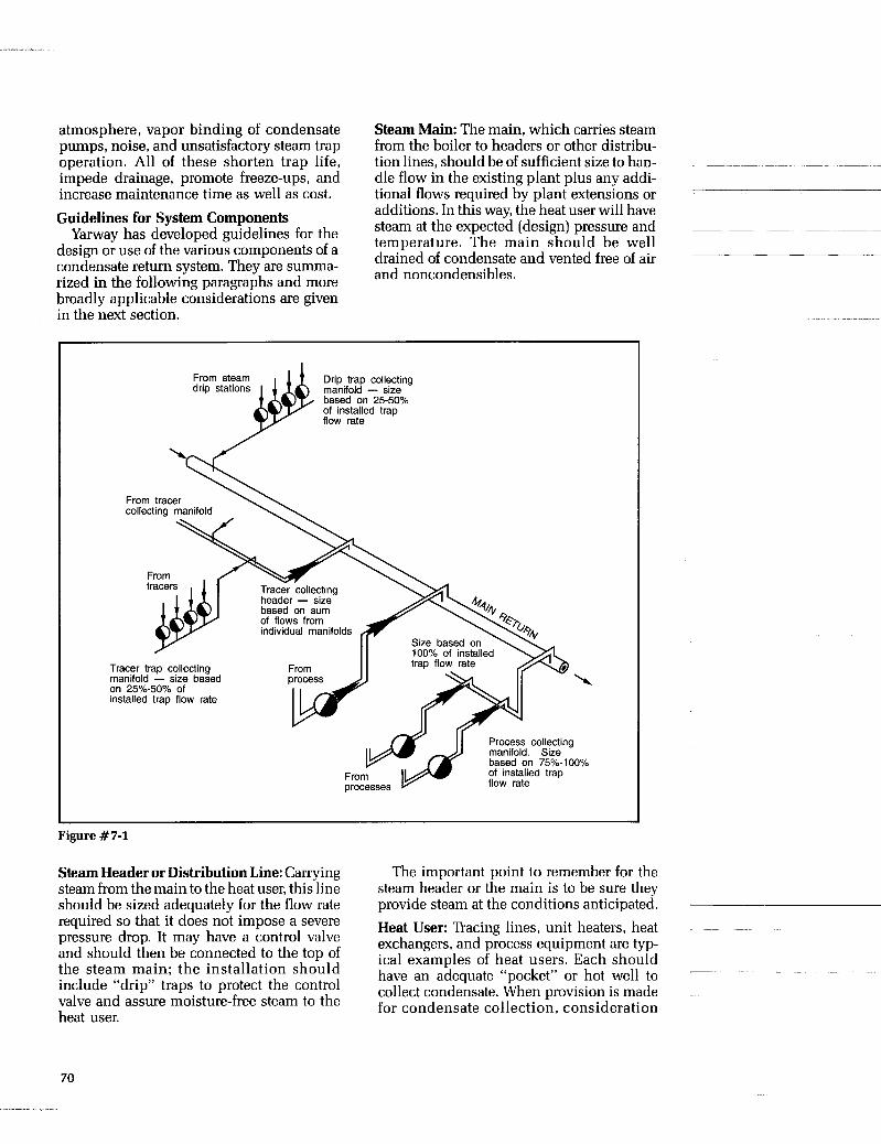
atmosphere, vapor binding of condensate pumps, noise, and unsatisfactory steam trap
impede drainage, promote freeze-ups, and increase maintenance time as well as cost.
Steam Main: The main, which carries steam from the boiler to headers or other distribu-
dle flow in the existing plant plus any addi- tional flows required by plant extensions or
operation. All of these shorten trap life, tion lines, should be of sufficient size to han- ~ ~~ ~ ~~
-
additions. In this way, theheat user will have steam at the expected (design) pressure and ~ ~ ~ ~ ~ ~
drained of condensate and vented free of air and noncondensibles.
Guidelines for System Components
design or use of the various components of a condensate return system. They are summa- rized in the following paragraphs and more
Yarway has guidelines for the temperature. The main should be well
broadly applicable c6nside;ations are given in the next section.
I From steam Drip trap collecting drip stations manifold - size
based on 25-50% of installed trap flow rate
on 25%-50% of installed trap flow rate
Process collecting manifold. Size based on 75%-100% of installed trap
Figure # 7-1
Steam Header or Distribution Line: Carrying steam from the main to the heat user, this line should be sized adequately for the flow rate required so that it does not impose a severe pressure drop. It may have a control valve and should then be connected to the top of the steam main; the installation should include “drip” traps to protect the control valve and assure moisture-free steam to the heat user.
The important point to remember for the steam header or the main is to be sure they provide steam at the conditions anticipated. Heat User: Tracing lines, unit heaters, heat exchangers, and process equipment are typ- ical examples of heat users. Each should have an adequate “pocket” or hot well to collect condensate. When provision is made for condensate collection, consideration
70
should be given to guidelines for other pro- cess equipment-such as those for pumps that drain a vessel for entrance loss and sepa- ration of steam bubbles from liquid condensate. Fittings: To handle condensate that forms at saturation temperature, fittings from the heat user to the steam trap should be full bore. Requirements are similar to those for the prevention of “pre-flash” at control valves. Maximum possible pressure at the steam trap inlet should be assured. Trap size should be reduced only at the trap outlet. Steam ’hap: Traps should be selected for specific applications. Design of the applica- tion should be taken into account, as well as the operating pressure and temperature ranges-especially if the heat user has a con- trol valve on the steam supply. Variations in condensate load should also be considered.
The steam trap should not be selected on thG basis of pipe size and should not be oversized. On process equipment, a trap may be judged oversized if it has a safety load factor (SLF) of 1O:l or more.
To provide gravity drainage to the trap, it should be installed below the equipment. It should also be installed for ease of checking and maintenance. Trap Discharge Line: Oversized piping rarely creates problems; the line should never be undersized. It should be adequate to handle flashing condensate. All traps dis- charging near saturation temperature, or where condensate temperature is above sat- uration temperature for the return line pres- sure, will form flash vapor. The trap manu- facturer’s recommendation should be fol- lowed a n d t h e l i n e s i zed for t h e instantaneous discharge rate of the trap.
If used, check valves should be suitable for the operating conditions; this requirement should be verified with the check valve man- ufacturer. If present, lift of the discharge line to the return line should be accounted for (a lift of 2 feet adds approximately 1 psi to the pressure at the steam trap outlet). The dis- charge line should enter the return line on the top and not be directly opposite any other discharge line (see Figure 7-2c and
General Design Considerations In the design of condensate return systems,
7-2d).
there are some general considerations which can affect sizing of more than one compo- nent. Also, some of these pertain to problems that can come from undersized and over- loaded systems. Steam ’haps: The instantaneous discharge rate of the trap can contribute to overloading of the return line. If the trap is of the “fail open” type, the amount of steam it can put into the line must be allowed for.
Because traps differ in operating princi- ples, some may tend to get “hot” when dis- charging into high pressure. This can cause accelerated wear of such traps as well as overloading or over-pressuring of the return line. Risk of steam loss also increases. Fur- ther, some types of traps tend to back up condensate if return pressures are elevated. Condensate Load: When the steam trap is sized, the smallest possible SLF should be used. Variations in ambient conditions must be checked out as to having a significant influence on condensate load, steam pres- sures, or condensate lines. Winter, for exam- ple, tends to result in lower steam pressures and higher return pressures. Sizing of the system may also be significantly affected by start-up loads. Piping: Because it is very likely that the pip- ing will have to serve some future plant expansion, it is best to provide for such growth in the initial design.
Allowances should be made for possible damage to piping. One cause is high velocity liquid that can result in erosion. Also, there can be excessive noise andfor cavitation damage. Corrosion is a frequent problem and is specifically important if erosion is also present.
Deposition of “dirt” reduces pipe bore and thus is a problem. Collection Headers: A separate return line may be advisable for each steam header pres- sure. This prevents discharge of a high pres- sure system from interfering with drainage and proper operation of a lower pressure system. Collection Vessel (or Receiver Tank): A ves- sel of sufficient size (volume) should be used, with the quantity of flash vapor taken into account. Its location should permit grav- ity flow from the return line into it.
71

If pumps are used to drain the liquid from the tank, there must be adequate NPSH (net positive suction head) on the pumps for the liquid temperature involved. Pumped liquid should be figured to be at saturation tempera- ture for the pressure in the vessel.
Vents and reliefs should be added, as needed and required by appropriate codes and standards. Also, transient loads should be allowed for; these include start ups, bypasses, and failed traps that may blow into the system.
Overloaded receivers result in venting of excessive flash vapor and loss of energy. If the return is to a condenser, excessive cool- ing water is used.
If the collecting vessel is over-pressurized, liquid temperature can be too high for the selected condensate pump. This can result in vapor binding of the pump and damage to the pump itself. Insulation: Insulation of the return system helps conserve energy, but it maintains high flashing fluid temperatures that can make fluid handling difficult. Fluid handling problems, however, are overcdme by proper regard for the nature of hot condensate and proper selection of components. Safety: Settings and size of relief valves and vents should be reviewed, especially if these must relieve a flashing liquid. As mentioned previously, transient situations-such as start up loads, open bypasses and blowing traps-should be allowed for. Return Line Installation 1. For gravity flow, the line should slope toward the receiver (see Figure 7-2a). Prefera- bly, the slope should be constant; risers and pockets that produce shock and water ham- mer should be avoided. 2. With eccentric reducers, to accommodate larger pipe for larger loads, expansion should be on the bottom of the pipe (see Figure 7-2b). 3. Discharge lines should be into the top of return lines so that they discharge into the vapor space and thus reduce noise (see Fig- ure 7-2c). 4. Discharge lines should be staggered to minimize noise, high local back pressure, and potentials for erosion (see Figure 7-2d).
a. Slope toward receiver.
dpH Flow L-- Slope
b. Expand on bottom. Slope
d L E c c e n t r i c J
Reducers
c. Discharge in top. T T r a p Discharge Line-
A- A d. Discharge not opposite.
/ Flow
Figure #7-2
5. If heat using equipment must be gravity drained, the trap discharge line and the return line must be below the drainage point of the heat user. The return line should be at least two or three feet below the heat user outlet. Care should be taken with regard to possible freezing situations. 6. Alignment and support should be ade- quate for the main return line. Anchors are normally required. The code for Power Pip- ing, ANSI B31.1, should be referred to. Con- sideration must be given to the weight of pipe itself, fittings, flanges, valves, insula- tion, and the fluid itself. The fluid should be assumed as being all liquid because hydro- static testing is probably needed.
Other potential factors-such as wind, snow, ice; shock, seismic effects, vibration, and thermal stresses-need to be included in the considerations. Estimating Return Line Size and Max. Load
Figure 7-3 is a nomograph that can be used for estimating the return line I.D. and also maximum load (condensate rate) that a given
~ _ _ _ _
72
. .

' return line can handle. There are three basic elements involved in such estimates; these are defined by the equation:
W = (Factor X) (Factor Y) When: W = maximum discharge rate (catalog rat-
ings in lb/hr) of all steam traps dis- charging into the return line, multi- plied by a percentage that depends upon the trap application (25 to 50% for drips and tracings and 75 to 100% for process).
Alternately, for a given return line, W = maximum carrying capacity in lb/hr of
flashing condensate for all steam traps in the system
X = flash factor for various steam trap inlet pressures, PI, and flash tank pressures, P,, in psig. See Figure 7-3.
Y = pipe factor for various return line 1.D.k in inches and equivalent pipe lengths, Le, in feet. See Figure 7-3.
Included in factor X are considerations for a limiting pressure drop, percent of vapor formed, and the average density of the two- phase mixture (the latter is assumed homog- eneous). Included in factor Y is a pipe fric- tion factor for complete turbulent flow; this factor is based upon Figure 20 in the Hydraulic Institute Pipe Friction Manual for steel pipe.
Equivalent pipe length, Le, should include the resistance of all fittings. If this is not known, at least 40% should be added to the actual linear run of pipe.
Two examples will illustrate how the nomograph can be used in solving for return ' line size (Case I) and maximum load (lb/hr) that a return line can carry (Case 11). Dashed lines on Figure 7-3 and 7-4 aid in following the use of the various curves. Sizing Flash and Receiver Tanks
There are certain characteristics of a con- densate return system that can affect how flash and receiver tanks are applied. These will be considered before the matter of tank sizing is covered.
Condensate and flash vapor should be piped into the top of the receiver. If the liquid condensate is returned, but no attempt is made to use the flash vapor, the receiver can be vented from the top to atmosphere.
An unvented receiver is satisfactory as long as the heat in the flash vapor can be absorbed in the receiver while the conden- sate is being pumped back to the boiler feed tank. If the flash enters the closed receiver faster than it can be absorbed, however, pres- sure in the receiver and return lines can inter- fere with performance of the system steam traps. Appropriate safety and relief valves are necessary.
In a flash condensate recovery system, a helpful and sometimes indispensable adjunct to the receiver is a flash tank that operates at some pressure above atmo- spheric. The flash condensate and its liquid are directed into the flash tank either through a top inlet or centrifugally through a side inlet near the top. Figure 7-5 illustrates these connections as well as steam and water outlets.
High Pressure Low pressure flash steam Condensate from traps - I - I
Condensate pump
Condensate and flash steam recovery system. I Figure #7-5
Rule-of-Thumb Sizing Method One method by which a flash tank can be sized is based on the assumption that the lb/hr of steam that can be flashed per square foot of water surface is three times the absolute pressure
75
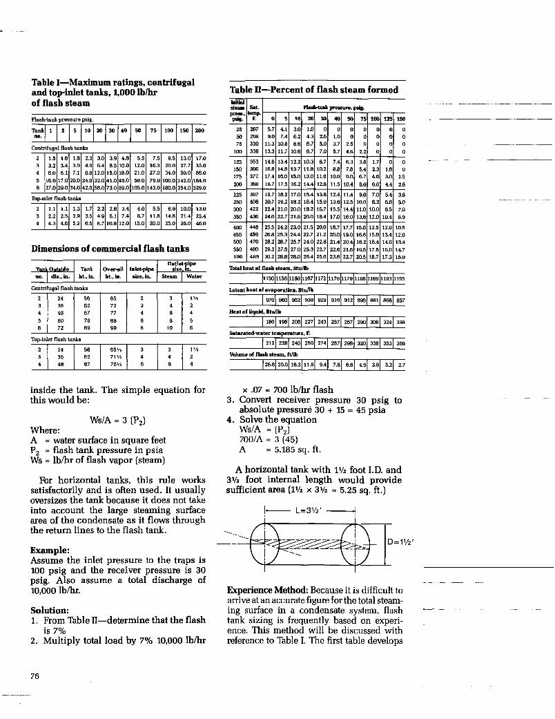
Table I-Maximum ratings, centrifugal and top-inlet tanks, 1,000 l b h of flash steam
Tank 1 2 DO.
Centrifugal flash
2 1.5 1.6 3 3.2 3.4 4 6.0 6.1 5 16.0 17.0 6 27.0 29.0
Topinlet flash
2 1.1 1.1 3 2.2 2.5 4 4.3 4.6
5 10 20 30 40 50 75 100 150 200
tanks 1.8 2.3 3.0 3.9 4.8 5.5 7.5 9.5 13.0 17.0 3.9 4.9 6.4 8.5 10.0 12.0 16.3 20.0 27.7 35.0 7.1 8.8 12.0 15.0 18.0 21.0 27.0 34.0 50.0 66.0
20.0 24.0 32.0 41.0 49.0 58.0 79.0 100.0 142.0 184.0 34.0 42.0 58.0 73.0 89.0 105.0 142.0 180.0 254.0 329.0
tanks
1.3 1.7 2.2 2.8 3.4 4.0 5.5 6.9 10.0 13.0 2.9 3.5 4.9 6.1 7.4 8.7 11.8 14.8 21.4 25.4 5.2 6.5 8.7 10.8 12.0 15.0 20.0 25.0 36.0 46.0
Tank Outside no. I &..in.
Centrifuunal flash tanks
OdJili Tank Overall Inlet-pipe
ht..in. %in. size,in. Steam I Water 11501156116011671172 117611791185118911931195
Towinlet flash tanks
2 3 4 5 6
inside the tank. The simple equation for this would be:
24 56 65 2 3 1% 36 62 72 3 4 2 48 67 77 4 6 4 60 78 88 6 8 5 72 89 99 8 10 6
WS/A = 3 (P2) Where: A = water surface in square feet P, = flash tank pressure in psia Ws = l bh r of flash vapor (steam)
For horizontal tanks, this rule works satisfactorily and is often used. It usually oversizes the tank because it does not take into account the large steaming surface area of the condensate as it flows through the return lines to the flash tank.
970
Example: Assume the inlet pressure to the traps is 100 psig and the receiver pressure is 30 psig. Also assume a total discharge of 10,000 lbhr.
980 952 939 929 919 912 895 8B1 868 857
Solution: 1. From Table 11-determine that the flash
is 7% 2. Multiply total load by 7% 10,000 lbhr
180 196 208 227
Table II-Percent of flash steam formed
243 257 267 290 309 324 338
~ ~ ~~~
Total beat of flash steam, Btdlb
212 228 240 259 274 287 288 320 338 353 366
26.8
3.
4.
20.01 16.31 11.9 9.41 7.81 6.61 4.91 3.91 3.21 2.7
x .07 = 700 lbhr flash Convert receiver pressure 30 psig to absolute pressure 30 + 15 = 45 psia Solve the equation WS/A = (PJ 7OOIA = 3 (45) A = 5.185 Sq. ft.
A horizontal tank with 1% foot I.D. and 3% foot internal length would provide sufficient area (1% x 3% = 5.25 sq. ft.)
b- L=3’/2’ - I
~
Experience Method: Because it is difficult to arrive at an accurate figure for the total steam- ing surface in a condensate system, flash tank sizing is frequently based on experi- ence. This method will be discussed with reference to Table I. The first table develops
76

. ---
the dimensions as well as the design of the tank Figure 7-6 illustrates the height dimen- sions and identifies the several inlets and outlets.
Table I1 tabulates percentages of flash vapor formed at various values of flash-tank pressures and initial steam pressures. Its use is discussed later.
Table I gives separate ratings for (a) cen- trifugal flash tanks and (b) top-inlet tanks. Size for size, ratings for top-inlet tanks are approximately 70% of those for centrifugal inlet tanks. In the centrifugal type, the con- densate spirals around the inside of the tank as it falls to the bottom; the longer path pro- vides more time and surface for steam flashing.
Separation of vapor from liquid in the tank is important. This is frequently improved by insertion of a screen or “demister.”
When the type and size of the flash tank are being chosen, it should be born in mind that, if operating pressure is increased, the permissible velocity of flash steam entering the tank should be lowered. This prevents condensate from being carried over into the low pressure steam line.
Ratings in Table I have been worked out to avoid the carrying over of condensate. In addition, the steam outlet line should be amply sized because its diameter bears directly on the exit velocity and, of course, on the possibility of condensate being car- ried over.
Sizing a Vented Receiver: Table I1 can also be used when the size of a vented condenser is being selected (a flash tank not being
flash vapor formed for various combinations of trap inlet and tank pressures.
If Table I1 is used in the selection of a vented receiver, the tank pressure should be assumed to be less than 5 psig, because the flash condensate will flow freely to the atmo- sphere. The amount of flash will actually be less than that for the maximum tank rating if the receiver is sized similarly to the tank.
In an existing installation, if the conden- sate pressure (and temperature) in the receiver is high enough to cause flashing and cavitation in the receiver pump, the diffi- culty can be alleviated temporarily by an increase in the size of the steam outlet or the vent. An alternate solution is to install a flash tank ahead of the receiver.
included). This table gives the amount of ~~ ~~ ~~ ~ ~
- --
~ ~ ~~ ~ ~~
Example of Calculating Tank Size (Including Flash Vapor and Its Heat Content)
As an example, in an industrial plant, there are 50 steam traps of several different sizes, discharging a total of 95,000 lb/hr of condensate from equipment operating at 150 psig. The condensate flows to a vented receiver that operates at 5 psig.
The first questions to be considered are: “How much flash vapor is formed if the con- densate is discharged very near to steam tem- perature?” And “How much heat is available
Sizing Top or Centrifugal Inlet Tank
Top inlet Centrifugal inlet
Blowdown Steam outlet-, rinlet
L W a t e r outlet
Figure #7-6
77
in the flash steam?” To determine the amount of flash vapor
formed, 150 psig is located in the left-hand column of Table I1 and lined up with the vertical column for a flash-tank pressure of 5 psig. This gives a figure of 14.8% for the amount of condensate that forms flash vapor. The quantity of flash vapor is thus 95,000 x 0.148 or 14,060 lb/hr.
To determine how much heat is available in this vapor, the latent heat of evaporation at 5 psig (at the vented receiver) is figured at 960 BTU/lb. The flash vapor thus provides nearly 13,500 million BTU/hr (14,060 x 960 = 13,497,600).
If this heat energy were used to heat water from 40 F to 140 F (a 100 Frise) and the water heater had an overall efficiency of 85%, 114,730 lb/hr of water would be heated (13,500,000 x 0.85 x %OO = 114,730). That is nearly 230 gpm. In addition, the condensate from the water heater could still be returned to an atmospheric pressure receiver and used again in the boiler.
Now the question can be considered: What size and type of flash tank would be selected and what would be its dimensions?
From the above calculations, it is assumed that the 14,060 lb/hr of flash steam is avail- able at 5 psig for heating equipment. In Table I the 5 psig value for flash tank pressure is located in the horizontal line of figures across the table. The vertical column under this figure gives the maximum ratings of flash tanks for this pressure (note that these are given in thousands of lb/hr so that 1.8, for example, means 1,800).
For the available 14,060 lb/hr of steam flow, a No. 5 tank with a maximum rating of 20,000 lb/hr (20.0 in the table) would be the proper size. The tank would have to be a centrifugal-inlet type because no standard top-inlet type shown in the table has suffi- cient capacity.
The lower part of the table gives the dimensions of the tank. The no. 5 centrifugal tank has a 60-in. diameter, an overall height of 88 in. and a 78411. tank height. It has a 6-in. condensate inlet, an 8-in. steam outlet, and a 5-in. liquid outlet at the bottom. (These
dimensions and connections are identified in Figure 7-6).
Flash Tank Sizing-Alternate Method ~ ~ ~
Another means of estimating the size of a flash tank and its associated piping is shown in the nomograph of Figure 7-7. The graph is entered from the left at given values of flow in lb/hr. As explained in the example below, the percent flash vapor table (Table 11) is used to determine the quantities of flash vapor, liquid, or total of the two, in lb/hr. All three of these flows are used in the estimation of dimensions.
The graph is entered at the proper flow value and pertinent tank dimensions are obtained at intersections with curves A through E. As illustrated in Figure 7-7, the dimensions, in inches, are:
~~ ~~ ~~~
A =
B =
C =
D =
E =
tank height, based on total liquid and flash flow. tank I.D., based on total liquid and flash flow. condensate inlet I.D. based on total liq- uid and flash flow. flash outlet I.D., based only on flash portion of arriving condensate. To assure adequate size, no allowance is made for condensation of flash. liquid outlet I.D., based on liquid por- tion of arriving condensate; no allow- ance is made for vapor condensation.
Example: Condensate to be collected is 30,000 lb/hr Nominal steam pressure is 150 psig Atmospheric pressure is to be maintained in tank Solution: 1.
2.
3. 4.
5.
6.
With reference to the table for percent flash vapor (Table 11), 150 psig to atmo- sphere gives 16.8% flash formed. 30,0001b/hrx0.168 = 5,04Olb/hrof flash vapor. 30,000 - 5,040 = 24,960 lb/hr of liquid. On Figure 7-7, at 30,000 lbihr, for total liquid and flash flow, dimensions for A, B, and C are determined as 47 in., 21 in. and 7 + in., respectively. On Figure 7-7, at 5,040 lb/hr of flash only, dimension D for the flash outlet I.D. is determined as 7 in. On Figure 7-7, at 24,960 lb/hr of liquid
~
78
7.
only, dimension E for the bottom liquid outlet I.D. is determined as 2 in. As a last step, applicable codes, stan- dards, and the like should be consulted for final design of the tank, walls, sup- ports, vents, reliefs, etc.
Design Factors That Save Money In the disposition of flash condensate,
money can be saved and operating head- aches avoided, if the following suggestions are heeded during the design of the conden- sate return system: 1. The return line should be sized to carry the flash vapor as well as the liquid conden- sate. Undersized lines cause high back- pressures at the traps; this reduces their effectiveness. 2. All steam equipment in the process should be analyzed to determine: (a) which units provide a continuous supply of high- temperature and high-pressure condensate that can be used, and (b) what equipment can operate on low-pressure flash condensate. Some equipment may be operating on boiler steam that is being reduced. Present operat- ing pressures and temperatures of this equip- ment should be checked; they may be higher than necessary.
3. For each case, the economies of using flash condensate should be checked out. This kind of saving, which goes on from year to year, should be balanced against the cost of installing the flash-condensate recovery system.
4. The pipeline that carries the flash vapor should be sized to lessen pressure drop between the flash tank and the low-pressure steam equipment. Also, money can be saved if the flash tank and pipeline are insulated. Further, condensate return lines should be insulated so that the maximum amount of flash steam is recovered. If the flash L-P heat- ing pipeline is long, drip traps should be installed.
5. The flash tank (and the receiver tank, if it is not vented) should be constructed in accordance with the ASME Unfired Pressure Vessel Code. Local codes, insurance com- pany requirements, and plant standards should be checked. The role of applicable codes and standards can not be minimized, ANSI B31.1 Code for Power Piping contains _ _ _ _ _ ~ - _ _ _ _ _ _ _ _ ~ ~
specific requirements; for example, Para. 102.2,5(c). 6. Types of traps already in use should be checked. Some types discharge condensate near steam temperature; others require that the condensate cool considerably before they open and discharge. The former types pro- duce more flash condensate and return the most heat. Some types of traps discharge subcooled condensate and the latent heat is lost to ambient if the system does not accom- modate backup.
7. A systematic plan for using flash conden- sate can save heat, cut fuel costs, and improve process efficiency. For the best results, however, the whole system and each of its parts should be carefully analyzed.
8. The condensate pump must handle very hot liquid. The pump, controls, and associ- ated piping should be carefully selected to assure proper operation. Under adverse con- ditions, the pump could “vapor bind” or cavitate. When this occurs, the liquid will not be removed from the flash tank or receiver. These vessels will then accumulate liquid and possibly over-pressurize.
In addition to reducing the effectiveness of the return system, over-pressurization can result in a safety hazard.
9. A frequent solution to over-pressurized tanks and systems is to drain them to sewer or grade. For vessels under these conditions, relief or safety valves should be considered. Again, applicable codes and standards for valve sizing, selection, and installation should be consulted.
~~ ~ ~~ ~~~ ~
_-
79

2
100,000
8
6 5
4
Step 4- Step 6-
2
10,000
8
6 Step 5-
4
3
t 2
2
100
Figure #7-7
80
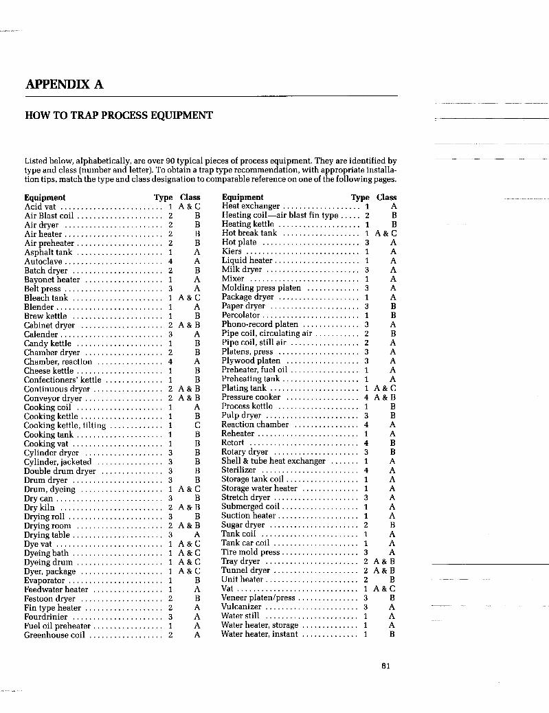
APPENDIX A
HOW TO TRAP PROCESS EQUIPMENT
Listed below, alphabetically, are over 90 typical pieces of process equipment. They are identified by type and class (number and letter). To obtain a trap type recommendation, with appropriate installa- tion tips, match the type and class designation to comparable reference on one of the following pages.
Equipment Type Class Acidvat ......................... 1 A & C Air Blast coil ..................... 2 B
Airheater.. ...................... 2 B
Asphalttank ..................... 1 A Autoclave ........................ 4 A
Bayonet heater . . . . . . . . . . . . . . . . . . . 1 A Beltpress ........................ 3 A Bleachtank ...................... 1 A & C Blender.. ........................ 1 A Brew kettle ...................... 1 B Cabinet dryer .................... 2 A & B Calender.. ....................... 3 A Candy kettle ..................... 1 B Chamber dryer . . . . . . . . . . . . . . . . . . . 2 B Chamber,reaction . . . . . . . . . . . . . . . . 4 A Cheese kettle ..................... 1 B Confectioners’ kettle . . . . . . . . . . . . . . 1 B Continuous dryer . . . . . . . . . . . . . . . . . 2 A & B Conveyor dryer.. . . . . . . . . . . . . . . . . . 2 A & B Cookingcoil ..................... 1 A Cooking kettle .................... 1 B Cooking kettle, tilting . . . . . . . . . . . . . 1 C Cooking tank ..................... 1 B Cookingvat ...................... 1 B
Cylinder, jacketed . . . . . . . . . . . . . . . . 3 B Double drum dryer . . . . . . . . . . . . . . . 3 B Drumdryer ...................... 3 B
Drycan .......................... 3 B
Dryingroll ....................... 3 B
Air dryer ........................ 2 B
Air preheater ..................... 2 B
Batchdryer ...................... 2 B
Cylinder dryer . . . . . . . . . . . . . . . . . . . 3 B
Drum, dyeing .................... 1 A & C
Drykiln ......................... 2 A & B
Dryingroom ..................... 2 A & B Dryingtable.. .................... 3 A Dyevat .......................... 1 A & C Dyeingbath ...................... 1 A & C Dyeingdrum ..................... 1 A & C Dyer, package .................... 1 A & C
Feedwaterheater . . . . . . . . . . . . . . . . . 1 A
Fintype heater . . . . . . . . . . . . . . . . . . . 2 A Fourdrinier ...................... 3 A Fuel oil preheater . . . . . . . . . . . . . . . . . 1 A Greenhousecoil . . . . . . . . . . . . . . . . . . 2 A
Evaporator ....................... 1 B
Festoon dryer .................... 2 B
Equipment 5 p e Class Heat exchanger.. . . . . . . . . . . . . . . . . . 1 A Heating coil-air blast fin type . . . . . 2 B Heating kettle .................... 1 B Hot breaktank . . . . . . . . . . . . . . . . . . . 1 A& C Hot plate ........................ 3 A Kiers ............................ 1 A Liquid heater.. . . . . . . . . . . . . . . . . . . . 1 A Milkdryer ....................... 3 A Mixer ........................... 1 A Molding press platen . . . . . . . . . . . . . 3 A Packagedryer .................... 1 A Paper dryer ...................... 3 B Percolator.. ...................... 1 B Phono-record platen . . . . . . . . . . . . . . 3 A Pipe coil, circulating air . . . . . . . . . . . 2 B Pipe coil, still air . . . . . . . . . . . . . . . . . 2 A Platens,press .................... 3 A Plywoodplaten . . . . . . . . . . . . . . . . . . 3 A Preheater, fuel oil . . . . . . . . . . . . . . . . . 1 A Preheatingtank . . . . . . . . . . . . . . . . . . . 1 A Platingtank ...................... 1 A & C Pressure cooker . . . . . . . . . . . . . . . . . . 4 A & B Process kettle .................... 1 B Pulp dryer ....................... 3 B Reactionchamber . . . . . . . . . . . . . . . . 4 A Reheater ......................... 1 A Retort ........................... 4 B Rotarydryer ..................... 3 B Shell & tube heat exchanger . . . . . . . 1 A Sterilizer ........................ 4 A Storagetankcoil.. . . . . . . . . . . . . . . . . 1 A Storage water heater . . . . . . . . . . . . . . 1 A Stretchdryer ..................... 3 A Submergedcoil.. . . . . . . . . . . . . . . . . . 1 A Suction heater.. . . . . . . . . . . . . . . . . . . 1 A
Tankcoil ........................ 1 A Tankcar coil ..................... 1 A Tiremold press.. . . . . . . . . . . . . . . . . . 3 A Tray dryer ....................... 2 A&B Tunneldryer ..................... 2 A&B Unit heater.. ..................... 2 B Vat .............................. 1 A & C Veneer platedpress . . . . . . . . . . . . . . . 3 B Vulcanizer ....................... 3 A Waterstill ....................... 1 A Water heater, storage . . . . . . . . . . . . . . 1 A Water heater, instant . . . . . . . . . . . . . . 1 B
Sugar dryer ...................... 2 B
81

EQUIPMENT TYPE 1, CLASS A (Steam heats a liquid indirectly through a metal
Steam m1. EQUIPMENT TYPE 1, CLASS A (Steam heats a liquid indirectly through a metal wall)
Steam
wall)
I % Tank Car
Typical Equipment Activity
Steam Pressures
Condensate Loads
Drainage To Trap Discharge From Trap
Ambient Conditions
Air Venting
Shock, Vibration & Water Hammer
Dirt & Corrosion
Steam a
0 Asphalt tank 0 Reheaters 0 Storage tank 0 Bayonet heaters 0 Suction heaters 0 Tank car Coils used to heat liquids (often very viscous) in large weather exposed equipment frequently in remote locations. Several coils may be employed due to the large surface area of containers. Will range from 5 to 125 psi with 40-75 psi being most typical. Generally constant pressure but occasionally will be modulated by pressure control valve. Wide ranges in final temperature of material being heated and in ambient temperatures results in especially large range of loads. Start-up loads are typically very heavy with seasonal weather variation having a significant influence.
Gravity drainage is the normal condition.
Generally to open drain. Condensate return systems are often miss- ing due to distance from power house and low pressures.
Vary as widely as weather conditions themselves-arctic to equi- torial desert. Prompt venting of air is desirable when frequent start-ups and rapid heating requirements are the norm.
May be present during start-up.
Corrosion of coils can lead to contamination of steam system by material being heated.
Recommended Traps
Desired Characteristics
Rugged, fail open, self-draining- with good air handling
Installation Tips
Strainer with suitable blow-down valve should be placed ahead of trap. A suitable drop or collecting leg (2’-3’) is desirable for bimetallic trap.
82
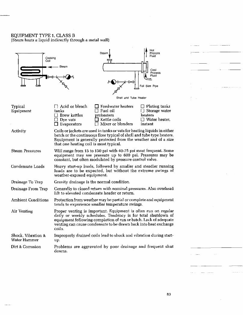
EQUIPMENT TYPE 1, CLASS B (Steam heats a liquid indirectly through a metal wall)
Cooking Coil I
Steam
!E%-+@+ Typical Equipment
Activity
Steam Pressures
Condensate Loads
Drainage To Trap
Drainage From Trap
Ambient Conditions
Air Venting
Shock, Vibration & Water Hammer
Dirt & Corrosion
0 Acid or bleach tanks 0 Brew kettles 0 Dye vats
Evaporators
J. Steam
_ - Cool
Full Size Pipe
Shell and Tube Heater
Feedwater heaters 0 Fuel oil preheaters heaters
Kettle coils 0 Mixer or blenders instant
0 Plating tanks c3 Storage water
I7 Water heater,
Coils or jackets are used in tanks or vats for heating liquids in either batch or the continuous flow typical of shell and tube type heaters. Equipment is generally protected from the weather and of a size that one heating coil is most typical.
Will range from 15 to 150 psi with 40-75 psi most frequent. Some equipment may see pressure up to 600 psi. Pressures may be constant, but often modulated by pressure control valve. Heavy start-up loads, followed by smaller and steadier running loads are to be expected, but without the extreme swings of weather-exposed equipment. Gravity drainage is the normal condition.
Generally to closed return with nominal pressures. Also overhead lift to elevated condensate header or return. Protection from weather may be partial or complete and equipment tends to experience smaller temperature swings. Proper venting is important. Equipment is often run on regular daily or weekly schedules. Tendency is for total shutdown of equipment following completion of run or batch. Lack of adequate venting can cause condensate to be drawn back into heat exchange coils. Improperly drained coils lead to shock and vibration during start- UP. Problems are aggravated by poor drainage and frequent shut downs.
~~
83

Continued. . . EQUIPMENT TYPE 1, CLASS B (Steam heats a liquid indirectly through a metal wall)
Recommended Traps
Desired Characteristics
Rugged, fail open, good air handling, rapid response rate, and discharge con- densate at close to steam temperatures.
Installation Tips
Strainer with suitable blow-down valve should be placed ahead of trap. A vertical drop leg ahead of trap is also recommended.
84

EQUIPMENT TYPE 1, CLASS C (Steam heats a liquid indirectly through a metal wall)
Air Vent Steam
.y Submerged e
Lift Fitting1 (See Fig. 5-2)
Typical Equipment
Activity
Steam Pressure
Condensate Loads
Drainage To Trap
Discharge From Trap
Ambient Conditions
Air Venting
Shock, Vibration & Water Hammer
Dirt & Corrosion
Steam
T
Jacketed Kettle
Syphon on Tilting Kettle
Air Vent
T O Cooking kettle, tilting 0 Candy kettle 0 Embossed coils 0 Tanks with elevated discharge
Liquids or materials are heated or cooked in jacketed kettles or tanks with submerged coils. All require raising discharge to the trap. Generally 5 to 125 psi with most frequently experienced pressures in the middle of this range.
Start-up loads heaviest with running loads lighter.
Condensate is passed to trap through use of a lift fitting that creates a water seal or reaches trap through syphon tube in case of tilting kettle. May be either to an open drain or a closed pressurized return. Equipment is generally protected from the weather and unlikely to see extreme temperatures (either) hot or cold.
Frequent start-up and the need to get equipment hot quickly requires a good air venting.
May be present during start-up.
Poor drainage and frequent start-ups increases potential for corro- sion.
Recommended Traps
Desired Characteristics Resistant to steam binding, rapid response, discharge condensate at close to steam temperatures, rugged, fail open, resistant to water hammer and shock.
Installation Tips
Auxiliary air vents are helpful. Lift leg or syphon should be a smaller pipe size than trap to reduce tendency for steam binding.
85

EQUIPMENT TYPE 2, CLASS A (Steam heats air/gas indirectly through a metal wall)
Auxiliary Steam
SloDe slope -
Pipe Coils -- / Typical
Equipment
Activity
Steam Pressure
Condensate Loads
Drainage To Trap
Discharge From Trap
Ambient Conditions
Air Venting Shock, Vibration & Water Hammer
Dirt & Corrosion
0 Dry kiln (without fans) 0 Greenhouse coil Space heating or drying of materials in enclosed equipment with natural air circulation. Fans or blowers are not employed.
Typically 5 to 50 psi with fluctuation occurring during start-ups. Normally constant pressure without control valves. Will vary widely depending on the size of the exposed surface area of the coils. Loads will be heaviest at start-up and rather steady thereafter.
Gravity drainage is important with amply sized collecting leg required to prevent condensate backup into coils. Gravity to closed return, low pressure to vacuum.
Generally protected from weather because installation is inside building or structure. Seasonal changes can expose shut-down system to freezing conditions.
Important to assure fast start-ups. On start-up hot condensate, flowing into improperly drained coils or return system, can create shock and vibration. May be heavy due to seasonal use, long shut-downs possibly in flooded conditions.
0 Drying room
Recommended Traps
Desired Characteristics
Rugged, good air handling, medium response rate, corrosion resistant.
Installation Tips
Provide collecting leg and strainer with suitable blow-down valve ahead of trap.
86
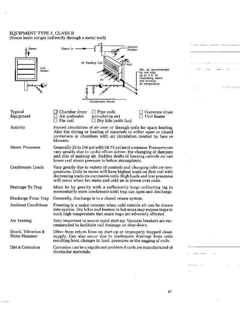
EQUIPMENT TYPE 2, CLASS B (Steam heats air/gas indirectly through a metal wall)
Steam
8, Unit Heater
Steam in
Air Heating Coil
Typical Equipment
Activity
Steam Pressures
Condensate Loads
Drainage To Trap
Discharge From Trap Ambient Conditions
Air Venting
Shock, Vibration & Water Hammer
Dirt & Corrosion
Min. as recommended by coil mfgr. up to 3 ft. for modulating steam and freezing air temperature
Condensate Return
Chamber dryer 0 Pipe coils 0 Conveyor dryer 0 Air preheater (circulating air) 0 Unit heater 0 Fin coil
Forced circulation of air over or through coils for space heating. Also the drying or heating of materials in either open or closed containers or chambers with air circulation created by fans or blowers.
Generally 25 to 150 psi with 50-75 psi most common. Pressures can vary greatly due to cyclic off-on action, the changing of dampers and mix of makeup air. Sudden drafts of freezing outside air can lower coil steam pressure to below atmospheric.
Vary greatly due to variety of controls and changing inlet air tem- peratures. Coils in series will have highest loads on first coil with decreasing loads on successive coils. High loads and low pressures will occur when fan starts and cold air is blown over coils.
Must be by gravity with a sufficiently large collecting leg to momentarily store condensate until trap can open and discharge. Generally, discharge is to a closed return system.
Freezing is a major concern when cold outside air can be drawn into system. Dry kilns and heaters in hot areas may expose traps to such high temperature that some traps are adversely affected.
Very important to assure rapid start-up. Vacuum breakers are rec- ommended to facilitate coil drainage on shut-down.
Often from return lines on start-up or improperly trapped steam supply. Can also occur due to inadequate drainage from coils resulting from changes in load, pressures or the sagging of coils.
Corrosion can be a significant problem if coils are manufactured of dissimilar materials. ~
0 Dry kiln (with fan)
87

Continued. . . EQUIPMENT TYPE 2, CLASS B (Steam heats air/gas indirectly through a metal wall)
Recommended Traps
Desired Characteristics Rugged, fast responding, hot discharge, fail open, self-draining-good air han- dling when subject to frequent start- ups.
Installation Tips
Trap should be well below unit (2 ft to 3 ft) with amply sized collection leg. Air vents on larger equipment to aid in start-up. Vacuum breakers help assure complete drainage of coils on shut-down. This is especially important if freezing temperatures are possible. Strainers with blow-down valves and test “T” reduce maintenance and simplify trap troubleshooting.
88
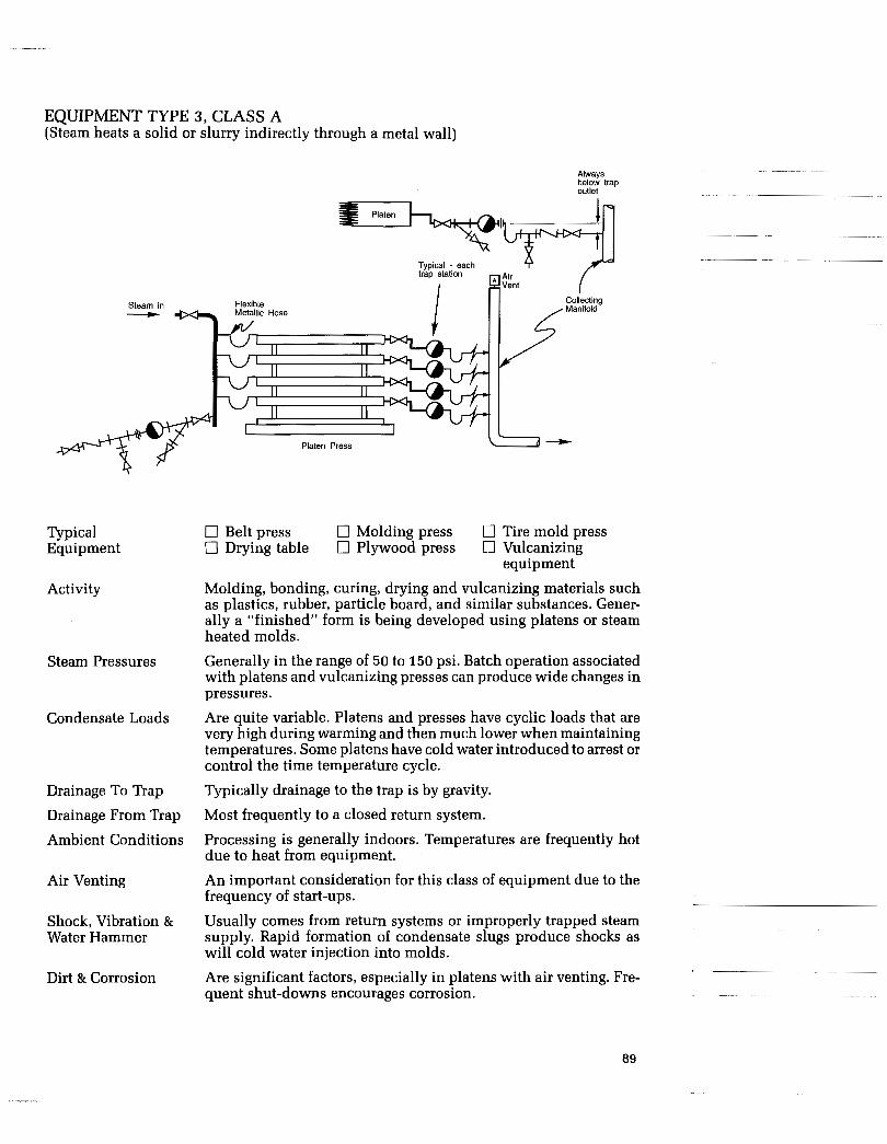
EQUIPMENT TYPE 3, CLASS A (Steam heats a solid or slurry indirectly through a metal wall)
Steam in +
1
Typical Equipment
Activity
Steam Pressures
Condensate Loads
Drainage To Trap Drainage From Trap
Ambient Conditions
Air Venting
Shock, Vibration & Water Hammer
Dirt & Corrosion
Always below trap outlet
Typical - each
I
I I Platen Press
0 Belt press 0 Molding press 0 Tire mold press 0 Drying table 0 Plywood press 0 Vulcanizing
Molding, bonding, curing, drying and vulcanizing materials such as plastics, rubber, particle board, and similar substances. Gener- ally a “finished” form is being developed using platens or steam heated molds. Generally in the range of 50 to 150 psi. Batch operation associated with platens and vulcanizing presses can produce wide changes in pressures. Are quite variable. Platens and presses have cyclic loads that are very high during warming and then much lower when maintaining temperatures. Some platens have cold water introduced to arrest or control the time temperature cycle.
Typically drainage to the trap is by gravity.
equipment
Most frequently to a closed return system.
Processing is generally indoors. Temperatures are frequently hot due to heat from equipment. An important consideration for this class of equipment due to the frequency of start-ups. Usually comes from return systems or improperly trapped steam supply. Rapid formation of condensate slugs produce shocks as will cold water injection into molds.
Are significant factors, especially in platens with air venting. Fre- quent shut-downs encourages corrosion. .~
89

Continued. . . EQUIPMENT TYPE 3, CLASS A (Steam heats a solid or slurry indirectly through a metal wall)
Recommended Traps
Desired Characteristics
Rugged, having hot discharge and fast response. Good air handling due to fre- quent startup of equipment. Failure mode should be “open.”
Installation Tips
Mount trap below platen’s lowest (open or u s e d ) position. Flexible hoses shoulc be care- fully selected for materials and proper bore diameter to assure easy drainage. They should be connected to provide positive head to the trap when it is stationary and downstream of hose. It is preferred that the trap be mounted on and below the platen outlet. A suitable flexi- ble hose should be connected to the trap outlet and the drain header. The connection at the drain header should always be below the trap outlet, whether the platen is open or closed.
90

EQUIPMENT TYPE 3, CLASS B (Steam heats a solid or slurry indirectly through a metal wall)
Steam
Syphon Drained Apparatus Steam
(Trap arrangements typical for cylinder ironer)
Typical Equipment
Activity
Steam Pressures
Condensate Loads
Drainage To Trap
Discharge From Trap Ambient Conditions
Air Venting
Shock, Vibration & Water Hammer
Dirt & Corrosion
\ Cylinder Dlyer
0 Calender 0 Paper dryer 0 Drum dryer 0 Dry can 0 Pulp dryer 0 Fourdrinier 0 Rotary dryer Continuous drying of materials is being performed by exposure to the heated surfaces of rotating cylinders or drums. Commonly used in the manufacture of felt, asbestos, rubber, textiles, paper and other sheet or fibrous materials, including foods and slurries of chemicals. Generally in the range of 75-150 psi. Once warm up is complete, pressures are reasonably constant. High startup loads and moderate running loads are typical. When many dryers are in series, the first several have highest loads and those toward the end have progressively smaller loads.
Syphon drainage is standard practice. Condensate moving up the syphon from the outer rim to the center of the drum is subject to reheating and flashing-steam binding of trap is common problem.
Discharge is generally to a closed condensate return system. Generally hot due to heat from the equipment. An important requirement during start-up when drums or cylin- ders contain large amounts of air.
Usually come from return systems or improperly trapped steam supply. Faulty or broken syphons can produce shocks. Can be a significant factor and is related to frequency of startups.
Recommended Traps
Desired Characteristics
Rugged, having hot discharge and fast response. Ability to handle flash steam by means of small bleed passage is a necessity. Failure mode should be “open.”
Installation Tips
Mount trap below cylinder. If flexible hose is used, care should be taken to assure it has an adequate bore and liner, materials suitable for steam service.
91

EQUIPMENT TYPE 4, CLASS A (Steam heats a solid directly)
Steam
Auxiliary t Air Vent
Typical 0 Reaction chamber 0 Retort 0 Pressure cooker Equipment
Activity Heating a material or producing a chemical reaction in an enclosed pressure vessel, by direct exposure to live steam. Condensate forms on product surfaces.
Steam Pressures Range from 15 to 150 psi with 15 to 50 being most typical. When the process is temperature controlled, steam temperatures can vary. On startup, pressures may be unexpectedly low. Can be very large on startup and quite low after temperature is reached. Must be gravity drainage with trap well below equipment.
Good condensate drainage after the trap is especially important in preventing contamination due to flooding. Equipment is usually in a building and may be subject to generally hot conditions.
Very important consideration due to potentially large volumes involved. Separate air vents are frequently used.
Shock may be generated in the return system and as a result of condensate forming in slugs. May be a problem because condensate can be contaminated from contact with material being heated. Because of frequent startups and exposure to air, corrosion problems can be expected.
Condensate Loads
Drainage To Trap
Discharge From Trap
Ambient Conditions
Air Venting
Shock, Vibration & Water Hammer
Dirt 81 Corrosion
Recommended Traps
Desired Characteristics Fail open and self draining desirable. Hot discharge and fast response with good air handling a must. Good dirt han- dling especially required i n some applications.
92
Continued. . . EQUIPMENT TYPE 4, CLASS A (Steam heats a solid directly)
Installation Tips
Place strainer (extra large where contamination is heavy) with blow-down valve ahead of trap and position for frequent servicing. Good drainage after trap is especially important with outdoor installations where freeze-up can be a problem. Bellows thermostatic trap mounted in vertical-up position is a good auxiliary air vent.
93

HOW TO TRAP STEAM MAINS
Recommended rip Pocket Diameter
& Lenath L
Activity
Steam Pressures
Condensate Loads
Drainage To Trap
Discharge From Trap
Ambient Conditions
Air Venting
Shock, Vibration & Water Hammer
Dirt & Corrosion
Recommended Traps
Removal of condensate from steam mains to protect steam equip- ment, prevent water hammer and maintain steam quality between boiler and point of use. Generally constant with some seasonal variation. Typical indus- trial pressures 100-600 psi. Utilities, pulp and paper, and chemical plants frequently higher.
Usually small and constant, 10 to 50 lb/hr per trap station except during start-up when loads can be quite heavy. Larger at ends of mains especially if earlier trapping has been inadequate.
Most commonly by gravity with trap below steam main. Occasion- ally piping in trenches will require lift fitting from a collector when trap is above main.
Commonly to closed and pressurized return systems but also to open atmospheric drains.
Vary widely. Range from underground tunnels to outdoor exposure to Arctic winters. Freezing is the most common concern.
Need is minimal because start-ups are infrequent. Some pipelines will have manual valves as air vents at start-up. Generally result from inadequate drainage of condensate moving at high velocity. Excessive warm-up rates can produce thermal shocks in return system. Also, negative pipe pitch and improperly located drip traps will produce problems.
No unusual problems beyond the oxides and dirt particles typical of any steam system.
Desired Characteristics Fail open, self draining, install in any pos i t ion . Toleran t of s u p e r h e a t . Capability of operating over wide pres- sure ranges aids standardization.
94

Continued.. . HOW TO TRAP STEAM MAINS
Installation Tips
Use of a standard pipeline “T” in main provides a drainage pocket so that condensate can get to a trap. A n extension to “T” is sometimes used to increase its storage volume. Strainers with blow-down valve and test “T” are recommended in addition to standard block valves for maintenance and checking.
95
. . . ..“ ..

HOW TO ESTIMATE STEAM MAIN CONDENSATE LOADS. Condensate Load, C,
(Warming Up) lb/hr per 100 ft of pipe
Nominal Pipesize, in.
1
18 884 20
Operating Steam Pressure, psi 10 I 100 I 200 1 300 I 400 I 600 I1000
3 1 5 1 7 1 9 I 10 I 1 3 I 1 3
I
24 I 721 I 802 1 857 I 900 I 945 11024 I1189 Assumed Conditions:
Warm-up Rate, 400Fihr Extra Strong Pipe Ambient, 0 Deg. F. Wind, 0 MPH Insulation 85% eff. 10% additional load for warming insulation
SO% of running load
Condensate Load, C, (Normal)
lb/hr per 100 ft of pipe
Assumed Conditions Ambient, 0 deg F, Insulation efficient Saturated Steam, Zero (0) Wind Velocity. Pipe surface temperatures same as steam temperature
NOTE Ambient temperature, wind and ram can influence loads ~~ ~
Comments 0 Increasing ambient temperature from OF to 1OOF will decrease condensate load approx- imately 30%.
mately 225%. 0 Increasing wind velocity from 0 mph to 15 mph will increase condensate load approxi-
~~
96

HOW TO TRAP STEAM TRACERS
Steam * Tracer 1 Tracer \ e
J h Steam +
Activity
Process Pipeline T Control T Valve
Maintaining the temperature of process material such as asphalt, sulfur, wax or other chemicals to aid in handling by preventing congealing, solidification or separation.
Prevent water lines, safety showers, pumps, valves, etc. from freeze-ups.
Maintain uniform temperatures in and around instruments.
Steam Pressures Typically 75-400 psi when tracing process materials, but 15-150 psi more common in freeze protection applications. Below 40 psi, condensate return problems increase in closed system when pres- sure differentials are not adequate for good drainage.
Low (0-40 lb/hr) and relatively steady, varying with seasonal changes. Long tracing runs, poor insulation, submerged lines can produce higher loads.
Most frequently by gravity, but lift drainage can be experienced when tracing occurs below grade in trenches. By gravity to open drains or closed returns-some pressurized and elevated. Freezing is the main concern. Most tracing is exposed to the weather but is also used in unheated buildings.
Of limited importance when tracing process materials because of infrequent start-ups. If start-ups are frequent during seasonal changes, freeze protection systems may have modest air venting needs. A minimal problem.
Generally modest in tracing of process lines. Dirt can be a problem in freeze protection systems due to corrosion products in season- ally activated lines and light sluggish condensate flows.
Condensate Loads
Drainage To Trap
Discharge From Trap
Ambient Conditions
Air Venting
~~ Shock, Vibration & Water Hammer Dirt & Corrosion
97
Continued. . . HOW TO TRAP TRACERS
Recommended Traps
Desired Characteristics
Fail open, self-draining, small and light- weight as frequently trap is not well supported. Easy checking is helpful as many traps are installed.
Installation Tips
When possible, locate traps close together using condensate return manifold. This also simplifies maintenance and trap checking. Provide strainers, test “T” and suitable block valves. Assure adequate pressure differential across trap for good drainage when discharg- ing to a closed and elevated return system.
98
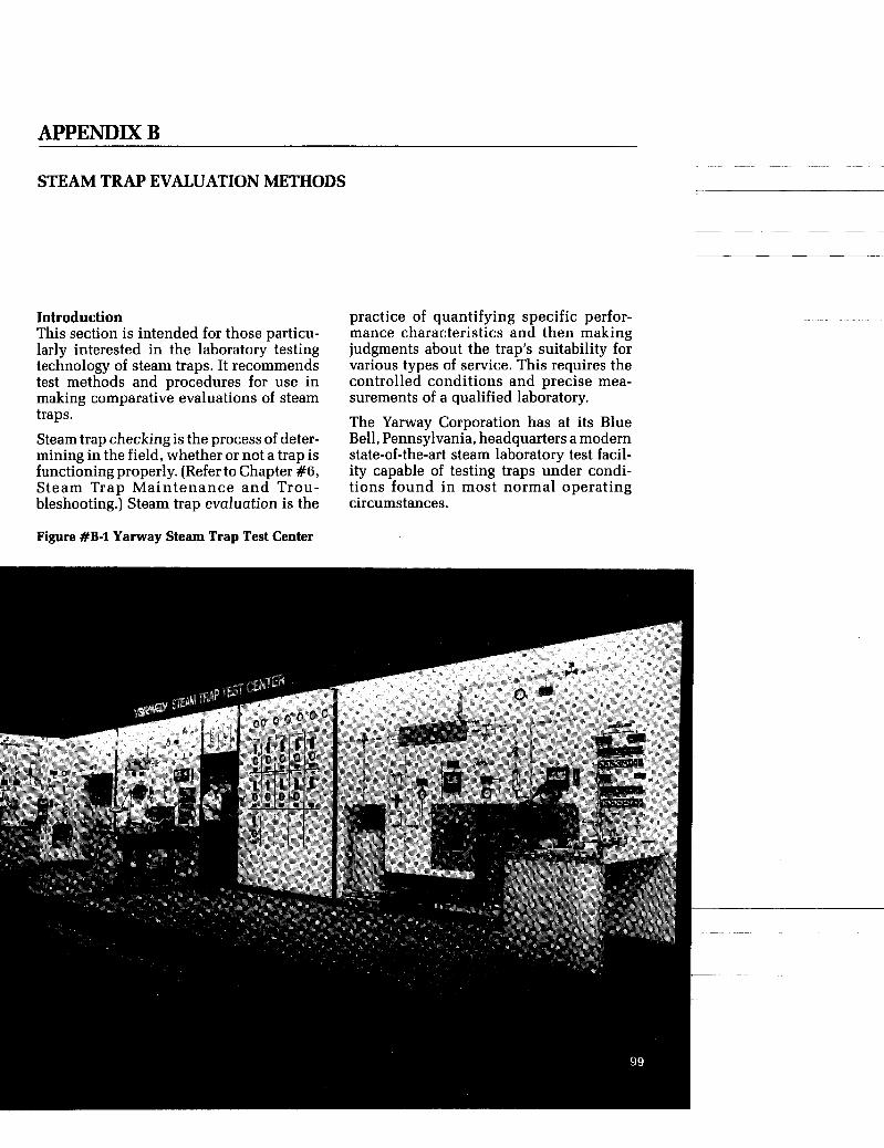
STEAM TRAP EVALUATION METHODS
Introduction This section is intended for those particu- larly interested in the laboratory testing technology of steam traps. It recommends test methods and procedures for use in making comparative evaluations of steam traps. Steam trap checking is the process of deter- mining in the field, whether or not a trap is functioning properly. (Refer to Chapter #6, Steam Trap Maintenance and Trou- bleshooting.) Steam trap evaluation is the
practice of quantifying specific perfor- mance characteristics and then making judgments about the trap’s suitability for various types of service. This requires the controlled conditions and precise mea- surements of a qualified laboratory. The Yarway Corporation has at its Blue Bell, Pennsylvania, headquarters a modern state-of-the-art steam laboratory test facil- ity capable of testing traps under condi- tions found in most normal operating circumstances.
Figure #B-1 Yarway Steam Trap Test Center

Evaluation Criteria Selecting the performance-related criteria that should be evaluated requires a thorough knowledge of the specific needs of differing steam trap applications. For example, process traps and protection traps serve different needs and should be evaluated accordingly. Five important evaluation criteria can properly be listed in different relative orders of importance, depending on the intended service of the trap being evaluated.
0 Protection (Drip & Tracer) Traps 1. Steam loss 2. Back pressure limit 3. Predominant failure mode 4. Capacity 5. Air handling on start-up
0 Process Traps 1. Capacity 2. Air handling on start-up 3. Predominant failure mode 4. Back pressure limit 5. Steam loss While the relative significance of these various criteria can be debated, it should be clear that an evaluation program should be tailored to specific application needs. Criteria Definitions 0 Steam Loss-The amount of saturated steam discharged during successive con- densate removal operations expressed in pounds per hour. A measure of trap efficiency. 0 Capacity-The amount of condensate that can be discharged continuously from a trap in a given period of time and under specific conditions or pressure differential and condensate temperature expressed in pounds per hour. 0 Back Pressure Limit-Back pressure limit is the maximum amount of back pres- sure that can be applied to the discharge side of the trap without causing malfunc- tion. (A decrease in discharge capacity with increasing back pressure is normal and not considered a malfunction.) Back pressure limits are expressed as the ratio of back pressure to supply pressure (in abso- lute units) expressed as a percent.
0 Failure Mode-The manner in which a trap is most likely to malfunction. It can be
either open or closed, depending on the specific design.
0 Air Hand l ing o n Star t -up-The capability of steam trap to vent air and other non-condensable gases during cold start-up conditions. At the present time there is no generally recognized expres- sion for this term. In its testing programs, Yarway Corporation expresses air han- dling capability in terms of actual cubic feet per hour passed under specific condi- tions of inlet and differential pressures.
Evaluation Philosophy In order to obtain meaningful results, traps should be tested under controlled condi- tions that are typical of actual field installations. A minimum of three (3) iden- tical traps is recommended for testing. This avoids basing conclusions on a single unit that may not be representative of the model being evaluated, due to manufactur- ing or other variations.
Well established trap manufacturers usu- ally publish reliable technical informa- tion. Unfortunately, the test conditions used are not always clearly stated, making valid competitive comparisons difficult, if not impossible. Published catalog informa- tion should be used with caution when employed for this purpose. Evaluative judgments are improved when comparisons between trap types (ther- modynamic, mechanical and thermo- static) are made in addition to the compari- sons be tween t r aps of a common technology.
Yarway Corpora t ion S t a n d a r d Test Conditions Yarway Corporation has established its own test conditions for use when making comparative evaluations of all types of traps:
1. Steam loss 0 Protection traps 100 psi supply, nominal condensate load 10 lb/hr
0 Process traps 100 psi supply, nominal condensate load at 10% of stated condensate capacity at the same operating pressure.
1
i
100
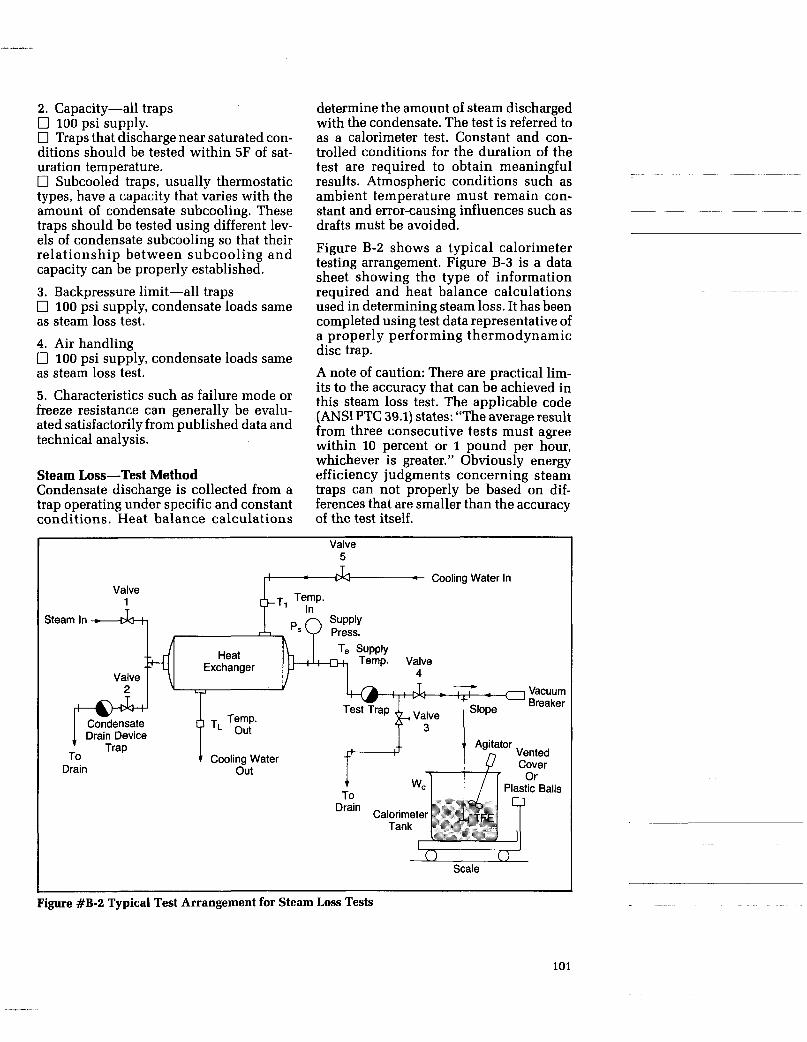
2. Capacity-all traps 0 100 psi supply. 0 Traps that discharge near saturated con- ditions should be tested within 5F of sat- uration temperature. 0 Subcooled traps, usually thermostatic types, have a capacity that varies with the amount of condensate subcooling. These traps should be tested using different lev- els of condensate subcooling so that their relationship between subcooling and capacity can be properly established.
3. Backpressure limit-all traps 0 100 psi supply, condensate loads same as steam loss test. 4. Air handling 0 100 psi supply, condensate loads same as steam loss test. 5. Characteristics such as failure mode or freeze resistance can generally be evalu- ated satisfactorily from published data and technical analysis.
Steam Loss-Test Method Condensate discharge is collected from a trap operating under specific and constant conditions. Heat balance calculations
determine the amount of steam discharged with the condensate. The test is referred to as a calorimeter test. Constant and con- trolled conditions for the duration of the test are required to obtain meaningful results. Atmospheric conditions such as ambient temperature must remain con- stant and error-causing influences such as drafts must be avoided. Figure B-2 shows a typical calorimeter testing arrangement. Figure B-3 is a data sheet showing the type of information required and heat balance calculations used in determining steam loss. It has been completed using test data representative of a properly performing thermodynamic disc trap. A note of caution: There are practical lim- its to the accuracy that can be achieved in this steam loss test. The applicable code (ANSI PTC 39.1) states: “The average result from three consecutive tests must agree within 10 percent or 1 pound per hour, whichever is greater.” Obviously energy efficiency judgments concerning steam traps can not properly be based on dif- ferences that are smaller than the accuracy of the test itself.
Valve 1 T
Valve 5
J, Cooling Water in
Steam In ---dal , I, , ,,, Q SUPP~Y Press.
Scale
I Figure #B-2 Typical Test Arrangement for Steam Loss Tests
101
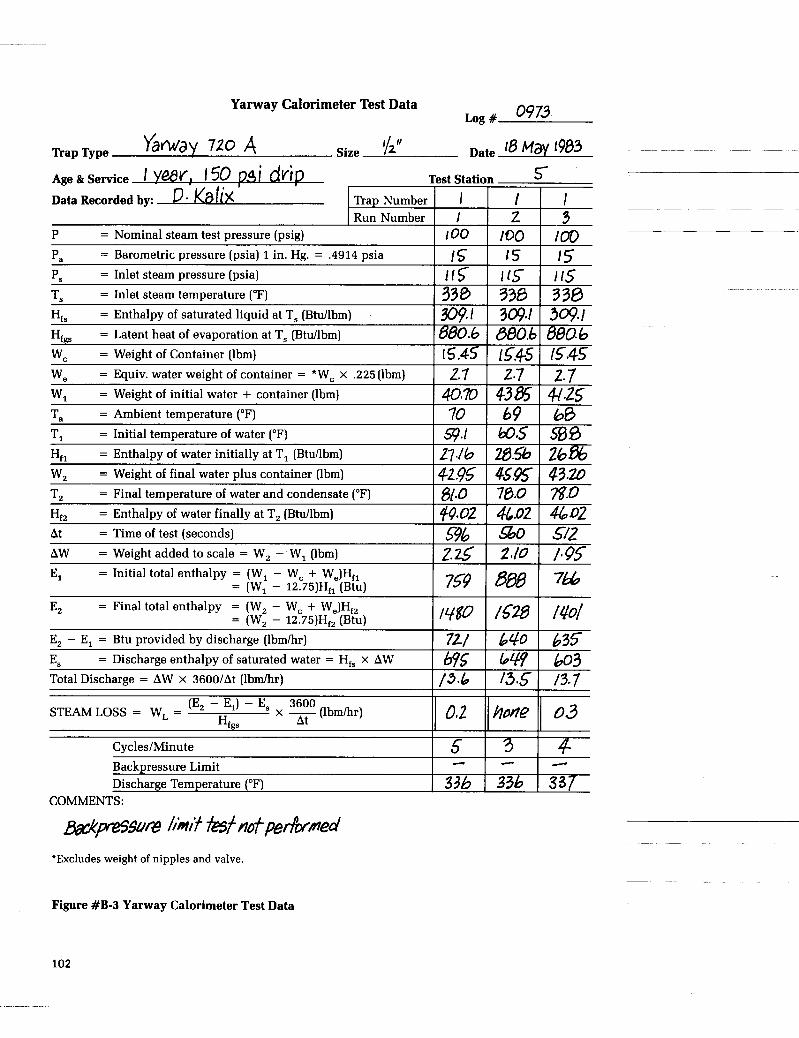
0973 Yarway Calorimeter Test Data Log #
AW = Weight added to scale = W, - W, (lbm) = Initial total enthalpy = (W, - W, + W,)Hf,
= (W, - 12.75)Hf1 (Btu) El
Age & Service YeSv! J 50 ?.4i d Test Station 5 ~~~~~
Data Recorded by: Gli%
2.25 2.10 /.os 759 800 766
. A ‘A.
E, - E, = Btu provided by discharge (lbmlhr) E, = Discharge enthalpy of saturated water = H,, x AW
E, = Final total enthalpy = (W, - W, + W,)Hf, = IW, - 12.751H,, lBtu1
721 L40 635 w5 649 LO3
0.2 (E, - E,) - E, 3600 x - (lbmlhr) At STEAMLOSS = W, =
Hfgs
Total Discharge = AW x 3600/At (lbmhr) I /3.6 I f3.5 I /3.7
hone 03
c Backpressure Limit
I I I
CyclesIMinute 1 5 1 3 1 4 - c d
COMMENTS:
Mps$ure hit &trtOfp,&med *Excludes weight of nipples and valve.
Figure #B-3 Yarway Calorimeter Test Data
102
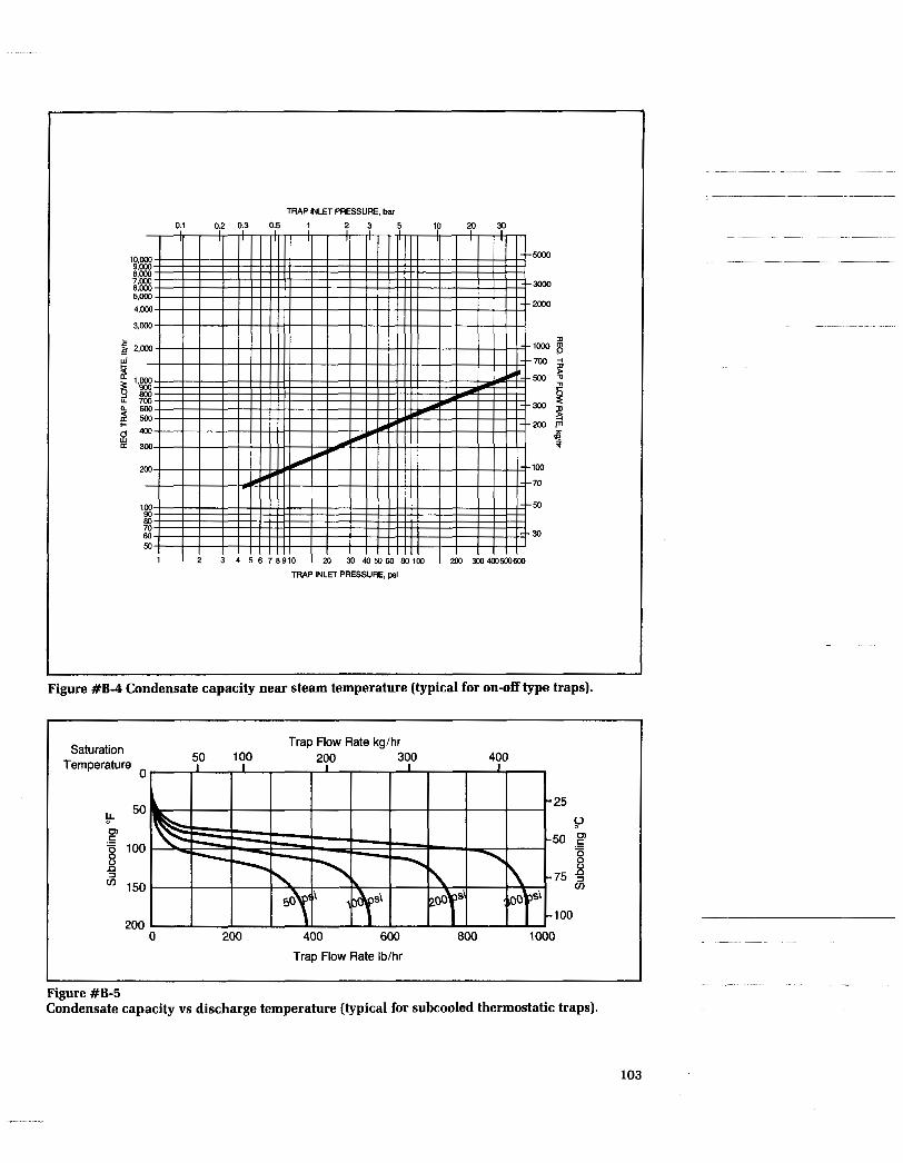
TRAP INLET PRESSURE, bar
3om
m
I) lwo 8 700
5 o o g
$ miil
B 5
100
70
50
30
1 I 2 3 4 5 6 7 8 9 1 0 I 20 30 405060 80100 I 200 3W4W500600 TRAP INLET PRESSURE, psi
Figure #B-4 Condensate capacity near steam temperature (typical for on-off type traps).
I Saturation
Temperature 0
.- F 8 E 100
cn 150 3
Trap Flow Rate kg/hr 50 100 200 300 400
1000 200
0 200 400 600 800
Trap Flow Rate Ib/hr
Figure #B-5 Condensate capacity vs discharge temperature (typical for subcooled thermostatic traps).
103

Test Procedure Start with all valves closed and tank empty (Reference Figure B-2). installation.
rates: (1) Cold condensate capacity for start-ups; and (2) Hot condensate capacity that will be available in the actual
1. Open valves 1, 2 and 3 to permit trap draining steam inlet line and test trap to operate at test pressure P,. 2. During warm-up, weigh and record weight of empty calorimeter tank W,, and record steam pressure P, and steam tem- perature T,. 3. Open valves 5 and 6 to allow flow of cooling water through heat exchanger to create desired condensate load on test device . Al low sys tem to come to equilibrium. 4. Fill calorimeter tank with enough water having a temperature T, at least 15F below ambient temperature T, to obtain a test run of reasonable duration. Weight and record water temperature T,, and weight of water plus calorimeter tank, W,. 5. Rapidly close valve 3 and open valve 4. Start timing interval when valve 4 is open. (Use of a 3-way valve is recommended to facilitate rapid closing and opening.) 6. Agitate the water in the calorimeter tank as necessary to insure uniform water temperature. 7. When the temperature of the water in the calorimeter tank is as many degrees above ambient as the initial temperature was below, rapidly close valve 4 and open valve 3, simultaneously recording the elapsed time, then the final water tempera- ture T,, and weight of water plus calorime- ter tank, W,. 8. Enter data in the calorimeter test data sheet and calculate steam loss. Refer to steam tables Appendix D for enthalpy val- ues (i.e., sensible heat of liquid and latent heat of evaporation) required by data sheet.
For reference, calorimeter test guidelines are published in the ANSI/ASME P'IC 39.1 performance test code for condensate removal devices by the American Society of Mechanical Engineers, United Engi- neering Center, 345 East 47th Street, New York, N.Y. 10017
For on-off type traps that discharge near s t eam t e m p e r a t u r e , u s u a l l y t h e r -
charge capacity is primarily a function of differential pressure and is proportional to the square root of differential pressure. (For estimating purposes, the steam tem- perature discharge capacity is approx- imately Y3 of the cold water capacity due to the choking effects of flash steam and changes in liquid density.)
For certain modulating traps (usually bimetallic thermostatic type traps), the discharge capacity is a function of both differential pressure and temperature. The discharge capacity will increase with increasing amounts of condensate sub- cooling until the maximum capacity is reached. Capacity data for a modulating type trap must reference both temperature and pressure.
Typic a1 c on d e n s a t e cap a c i t y d i s charge curves are presented in Figures B-4 and B-5. their different form results from the different operating principles of the traps being tested.
modynamic and mechanical traps, the dis- ~~ ~~ ~~~
Discharge Capacity Test Procedure (dynamic weight method) Start with all valves closed (Reference Fig- ure B-6). 1. Open valves 1 and 2 and fill accumula- tor tank to desired level. Close valve 1.
2 . Open valve 3 a n d heat water i n accumulator tank to desired temperature. Close valves 2 and 3 and open valve 4.
3. Fill barrel approximately half full of cold water. The end of the discharge pipe should be under water in the weigh tank. Balance scale lever arm, then add an appropriate weight to allow time for open- ing and closing valves.
~~ 4. Open valves 5 and 6 to heat pipe and
5. When thermal equilibrium is reached, close valve 6 and open valve 7.
Discharge Capacity-Test Method test trap. Condensate discharge capacity of steam traps varies with each type and make. Interest is directed to two distinct flow
104
.

Safety Vent supply valve + Press
Pressure
---El-- Open Pit
Notes: I . The piping from the accumulator to the test device shall be of the same diameter as the inlet connection on the
2. The distance between the sensors and the test device shall not exceed 20 interns\ pipe diameters. test device. The inlet to the piping from the accumulator shall be in the form of a well rounded entrance.
Figure #B-6 Typical arrangement for discharge capacity testing (dynamic weight method).
9. Calculate capacity in lb/hr. 6. When scale lever arm is balanced, start timing and add an appropriate weight to the yoke corresponding to the number of pounds of condensate to be collected. This should be less than the amount necessary to cause boiling of the water in the weigh tank. 7. When scale lever arm is again balanced, stop timing and close valve 5. 8. Observe and record the following data:
a. Elapsed time b. Ambient temperature T, (F) c . Barometric pressure, Pa (psia) d. Steam pressure and temperature,
e. Weight of condensate plus barrel at
f. Initial and final values of the following: (i) Temperature differential (T,-T,) F
(ii) Inlet pressure, PI (psig) (iii) Back pressure, P, (psig)
P, (psig) and T, (F).
start and finish, W, (lb),
Discharge capacity test guidelines are pub- lished in ANSI/ASME PTC 39.1 perfor- mance test code for condensate removal devices.
Backpressure-Test Method At the present time there is no generally accepted standard procedure for perform- ing backpressure tests. Experience has shown that backpressure limitations can be determined easily by installing a trap into a test rig having controlled inlet con- ditions, and with an outlet connected to a receiving tank, whose pressure can be reg- ulated, to simulate a closed return system. Either steam or air may be used to pressur- ize the tank. Assure its pressure rating is adequate for the test. This test is usually performed on thermodynamic traps.
~~
105
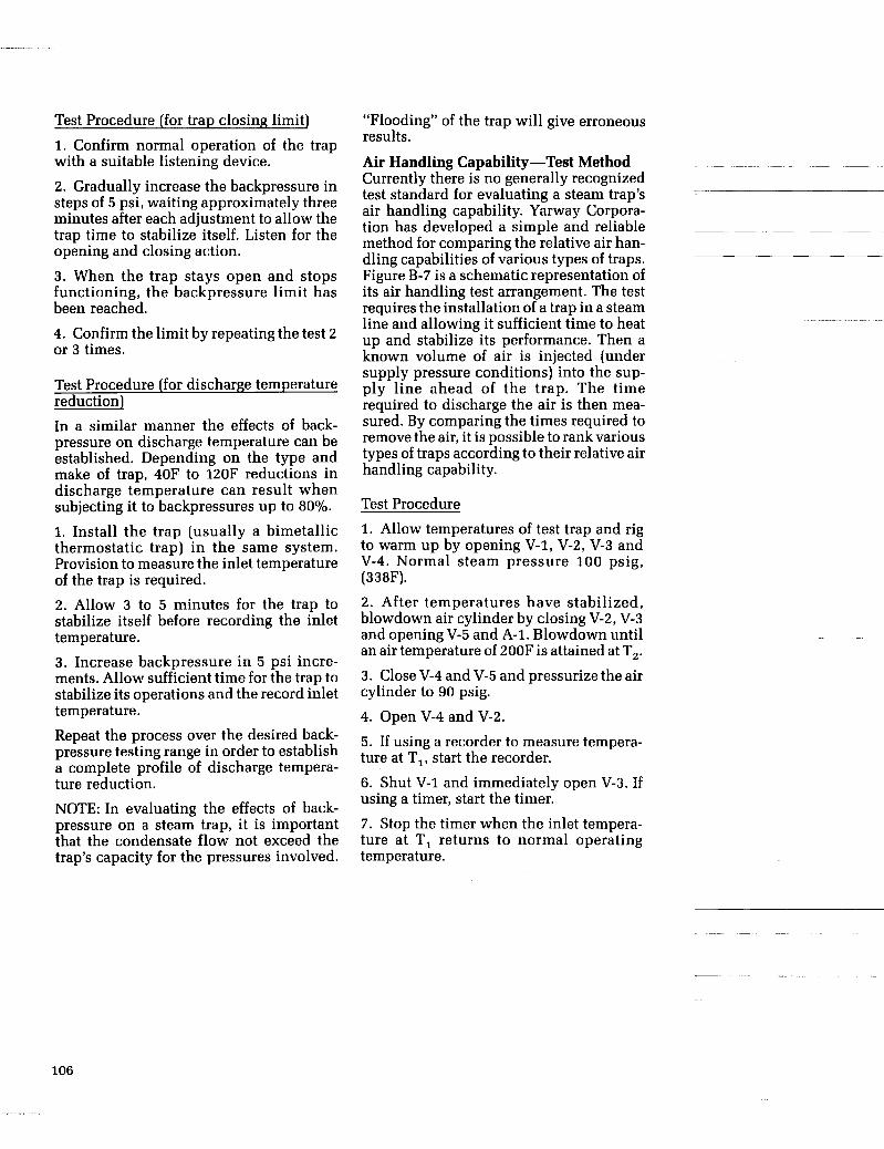
Test Procedure [for trap closing limit) 1. Confirm normal operation of the trap with a suitable listening device.
2. Gradually increase the backpressure in steps of 5 psi, waiting approximately three minutes after each adjustment to allow the trap time to stabilize itself. Listen for the opening and closing action.
3. When the trap stays open and stops functioning, the backpressure limit has been reached.
4. Confirm the limit by repeating the test 2 or 3 times.
Test Procedure (for discharge temperature reduction) In a similar manner the effects of back- pressure on discharge temperature can be established. Depending on the type and make of trap, 40F to 120F reductions in discharge temperature can result when subjecting it to backpressures up to 80%.
1. Install the trap (usually a bimetallic thermostatic trap) in the same system. Provision to measure the inlet temperature of the trap is required. 2. Allow 3 to 5 minutes for the trap to stabilize itself before recording the inlet temperature. 3. Increase backpressure in 5 psi incre- ments. Allow sufficient time for the trap to stabilize its operations and the record inlet temperature. Repeat the process over the desired back- pressure testing range in order to establish a complete profile of discharge tempera- ture reduction.
NOTE: In evaluating the effects of back- pressure on a steam trap, it is important that the condensate flow not exceed the trap’s capacity for the pressures involved.
“Flooding” of the trap will give erroneous results.
Currently there is no generally recognized test standard for evaluating a steam trap’s air handling capability. Yarway Corpora-
method for comparing the relative air han- dling capabilities of various types of traps. Figure B-7 is a schematic representation of its air handling test arrangement. The test requires the installation of a trap in a steam line and allowing it sufficient time to heat up and stabilize its performance. Then a known volume of air is injected (under supply pressure conditions) into the sup- ply line ahead of the trap. The time required to discharge the air is then mea- sured. By comparing the times required to remove the air, it is possible to rank various types of traps according to their relative air handling capability.
Air Handling Capability-Test Method ~~ ~~ ~
-
tion has developed a simple and reliable ~~~~~
Test Procedure 1. Allow temperatures of test trap and rig to warm up by opening V-1, V-2, V-3 and V-4. Normal steam pressure 100 psig, (338F).
2. After temperatures have stabilized, blowdown air cylinder by closing V-2, V-3 and opening V-5 and A-1. Blowdown until an air temperature of 200F is attained at T,. 3. Close V-4 and V-5 and pressurize the air cylinder to 90 psig. 4. Open V-4 and V-2.
5. If using a recorder to measure tempera- ture at TI, start the recorder. 6. Shut V-1 and immediately open V-3. If using a timer, start the timer. 7. Stop the timer when the inlet tempera- ture at TI returns to normal operating temperature.
106

Steam Supply
v-2 I r n 3essure
v-1
Test Trap
(Drain)
Air Cylinder
Q Pressure $4 V-6 (Drain)
Regulator I I
A-1 T & Air Supply
4 T2 Thermocouple
Figure #B-7 Steam Trap Air Handling Capability-Test Rig
107

APPENDIX C
GLOSSARY OF TERMS
0 Air binding
0 Blow-down valve
0 British Thermal
0 Capacity Unit (BTU)
0 Condensate 0 Cycle
0 Dirt pocket
0 Discharge temperature
0 Efficiency
0 Enthalpy
0 Flash steam
0 Flash tank
0 Latent heat of vaporization
0 Modulate
0 psia
0 psig
~-~ ~~
The process of a steam trap closing due to the presence of air rather than steam. This slows down the discharge of condensate and the ability of a steam system to reach its desired temperature (Reference Chapter #5, page 48).
A valve used when blowing pipeline dirt or scale from a strainer screen or boiler drum (Reference Figure 5-1, page 49).
The quantity of heat required to raise one pound of water one (I) degree fahrenheit (Reference Chapter #2, page 6) .
The maximum amount of condensate that can be discharged by a steam trap at specific conditions of temperature and pressure differential (between its inlet and outlet)-capacity is measured in pounds per hour (Reference Chapter #4, page 37).
The result of steam changing from vapor to a liquid. The opening and closing action of a steam trap that allows it to pass condensate and then stop the passage of steam. A length of pipe in the discharge line of steam heated equipment that allows the collection (by gravity) of pipeline scale and dirt (Reference Figure #5-1, page 49).
The temperature of condensate (measured at a steam trap’s inlet) while it is being discharged. Sometimes referred to as the tempera- ture at which a steam trap starts to open. (Reference Chapter #2, page 7 and Chapter #4, page 36).
See Appendix B, page 99, for steam testing under actual operating conditions. See also ASME Power Test Code ANSI PTC39.1.
The energy content of a fluid, including both heat and mechanical energy, BTU/lb-see Sensible, latent heat, and total heat of steam.
Steam that results when saturated water or condensate is dis- charged to a lower pressure. It is steam that could not exist at a higher pressure (Reference Chapter #2, page 9) .
A vessel or tank where flash steam is accumulated for subsequent use (Reference Chapter #5, Figure 5-3, page 51).
Heat that produces a change of state without a change in tempera- ture, such as changing water into steam-sometimes referred to simply as “latent heat” (Reference Chapter #2, page 6).
The partial opening and closing of a steam trap, thereby regulating the discharge flow of condensate. Modulation is in contrast to a full open/full closed mode of operation. Pounds per square inch absolute-a measure of pressure including atmospheric pressure (about 14.69 psi). Pounds per square inch gage-a measure of pressure excluding atmospheric pressure (about 14.69 psi).
~~
108

0 Safety load factor
0 Sizing
0 Saturated
0 Saturated steam
condensate
0 Saturation curve
0 Saturation temperature
0 Sensible heat
0 Steam -dry
-live
-wet
-total heat of
0 Steam binding
Steam separator
0 Steam tables
0 Steam tracing
A factor, by which the calculated condensate load is multiplied, to determine the capacity a trap should possess to properly serve its selected application. The safety load factor is used to accommodate system variables and uncertainties affecting the condensate flow rate (Reference Chapter #4, page 42).
The process of matching the condensate drainage requirements of an application to a steam trap having a suitable capacity (Reference Chapter #4, page 29).
Condensate that has a temperature equal to that of the steam with which it is in contact (Reference Chapter #2, page 6).
Steam that has a temperature equal to that of the condensate with which it is in contact (Reference Chapter #2, page 7).
Graphic representation of the boiling point of water at various pres- sures (the pressure and temperature at which saturated steam and condensate exist) (Reference Chapter #2, page 7).
The temperature at which saturated steam and condensate exist (Reference Chapter #2, Figure 2-3, page 7).
Heat that produces a temperature rise in a body (such as water) (Reference Chapter # 2 , page 6).
Steam having no water droplets suspended in it (Reference Chapter #2, page 6).
“Live steam” is an expression commonly used to describe steam that is still able to do useful work-in contrast to flash steam at atmospheric pressure.
Steam having fine water droplets suspended in it, and as a result, having a lower heat content than dry steam (Reference Chapter #2,
The sum of BTU’s per pound of both the sensible heat (of conden- sate) and the latent heat (of vaporization) (Reference Chapter #2, page 6). The process of steam keeping a steam trap closed and thereby preventing the discharge of condensate that has formed upstream of the trap. This condition results when the condensate discharge line to a steam trap is subjected to sufficient heating that the condensate in it is changed back into steam, thereby blocking the flow of con- densate to the trap (Reference Chapter #5, page 48).
A device that removes entrained water droplets from steam flow (Reference Chapter #5, page 50).
Tables that list the properties of steam and condensate at various pressures and temperatures (Reference Chapter #2, pages 9 and 115).
The use of steam to: (1) heat or maintain the temperature of a process liquid in a pipeline, (2) prevent water lines and related equipment from winter freeze-ups, and (3) provide uniform temperature in and around instruments so as to help maintain their calibration (Refer- ence Appendix A-11, page 85).
page 6).
109
0 Steam trap
-Cool
-Hot
-Process
-Protection
0 Steam trap Standard
0 Superheat 0 Subcooling
0 Suppression 0 Water hammer
A self-contained valve which automatically drains condensate and discharges air and non-condensible gases from a steam-containing pipe or vessel (Reference Chapter #3, page 13).
A steam trap that discharges condensate at temperatures signifi- cantly below saturation temperature is referred to as a “cool trap” even though it may be at a temperature well above 212 F (Reference
~~ ~ ~ ~~
Chapter #4, page 36). ~~~ ~~
A steam trap that discharges condensate at temperatures up to 10 degrees below saturation temperature (Reference Chapter #4, page 36).
A steam trap that discharges condensate from equipment used in the heating or production of some product as distinct from a “protection service” application.
A steam trap that discharges condensate from an application such as a steam main (to protect it from water hammer) or from a tracer application providing protection from freezing.
A preferred type of steam trap and piping configuration for remov- ing condensate from each designated piece of equipment in a steam system. Heat that is added to dry saturated steam. The temperature difference between that of steam and the conden- sate being discharged by a steam trap. This subcooling or suppression will be at least 2 or 3 degrees and sometimes much more. Certain applications benefit from steam traps that discharge condensate with a small amount of subcooling, while others will benefit from a large amount of subcooling.
(See “Subcooling”) The shock created when accumulated condensate is swept down a pipeline at high velocities and is slammed into valves, elbows, steam traps, or other fittings.
110

.
APPENDIX D
USEFUL TABLES
1 . Conversion Factors . . . . . . . . . . . . . . . . . . . . . . . . . . . . . . . . . . . . . . . . . . . . . . . . . 112
2 . Temperature Conversion Tables . . . . . . . . . . . . . . . . . . . . . . . . . . . . . . . . . . . . . 113
3 . Steam Tables (abbreviated) . . . . . . . . . . . . . . . . . . . . . . . . . . . . . . . . . . . . . . . . . . 115
4 . Sensible Heat of Liquid . . . . . . . . . . . . . . . . . . . . . . . . . . . . . . . . . . . . . . . . . . . . . 116
5 . Properties of Pipe . . . . . . . . . . . . . . . . . . . . . . . . . . . . . . . . . . . . . . . . . . . . . . . . . . 117 6 . Heat Transfer Coefficients . . . . . . . . . . . . . . . . . . . . . . . . . . . . . . . . . . . . . . . . . . . 118
7 . Specific Heats ...................................................... 119 8 . Standard Piping Symbols ........................................... 122
111

CONVERSION FACTORS Length 1 in = 25.4 mm 1 mm = .03937in 1 ft = 30.48 cm 1 meter = 3.28083 ft 1 micron = .001 mm
Area 1 in2 = 6.4516 cm2 1 ft2 = 929.03 SQ cm2 1 cm2 = 0.155 inz 1 cm2 = 0.0010764 ft2
Volume 1 in3 = 16.387 cm3 1 ft3 = 1728in3 1 ft3 = 7.4805 U.S. gal 1 ft3 = 6.229 British gal 1 ft3 = 28.317 liters i U.S. gal = 0.1337 ft3 1 U.S. gal = 231 in3
3.785 liters i&$gz = 1.20094 U.S. gal 1 British gal = 277.3 in3 1 British ea1 = 4.546 liters
-
1 liter = u61.023 in3 1 liter = 0.03531 ft3 1 liter = 0.2642 U.S. gal
Weight 1 ounce av = 28.35 g 1 lbav = 453.59g 1 am 0.03527ozav 1 g = 3 2 205 lb av 1 ft3 of water = 62.425 lb 1 U.S. a1 of water = 8.33 lb 1 in3 ofwater = 0.0361 lb 1 British gal of water = 10.04 lb 1 A3 of air at 60 F & 1 atm = 0.0764 lb
Velocity 1 ft per sec = 30.48 cm per sec 1 cm per sec = .032808 ft per sec
Flow 1 ft3 per sec = 448.83 a1 per min 1 ft3 per sec = 1699.3 fiters per min 1 U.S. gal per min = 0.002228 ft3 per sec 1 U.S. gal per min = 0.06308 liters per sec 1 cm3 per sec = 0.0021186 ft3 per min
Density 1 lb per ft3 = 16.018 kg er meter3 1 lb per ft3 = .0005787 I! per in3 1 kg per meter3 = 0.06243 lb per ft3 1 g per cm3 = 0.03613 lb per in3
Pressure 1 in of water = 0.03613 Ib per in2 1 in of water = 0.07355 in of Hg 1 ft of water = 0.4335 lb per in2 1 ft of water = 0.88265 in of Hg 1 in of mercury = 0.49116 Ib er in2 1 in of mercury = 13.596 in ofwater 1 in of mercury = 1.13299 ft of water 1 atmosphere = 14.696 Ib er in2 1 atmosphere = 760 mm ofHg 1 atmosphere = 29.921 in of Hg 1 atmosphere = 33.899 ft of water 1 lb per in2 = 27.70 in of water 1 lb per in2 = 2.036 in of Hg 1 lb per in2 = .0703066 kg per cm2 1 kg per cm2 = 14.223 lb per in2 1 dyne per cm2 = .0000145 lb per in2 1 micron = .00001943 lb per in2
Enerw __._-
I BTE = 777.97 ft/lb 1 erg = 9.4805 x BTU
7.3756 x 10⁻⁸ ft lb Efozatt hour = 2.655 x 106 ft Ib
1 kilowatt hour = 1.3410 hp hr 1 kg calorie = 3.968 BTU
Power 1 horsepower = 33,000 ft/lb per min 1 horsepower = 550 ft/lb pefsec 1 horsepower = 2,546.5 BTU per hr 1 horsepower = 745.7 watts 1 watt = 0.00134 horsepower 1 watt = 44.26 ft/lb per min
Temperature Temperature Fahrenheit (F) = 9/5 Celsius (C) + 32 = 9/4 R + 32 Temperature Celsius (C) = 5/9 Fahrenheit (F) - 32 = 514 R Temperature Reaumur (R) = 4/9 Fahrenheit (F) - 32 = 4/5 C Absolute Temperature Celsius or Kelvin K) = Degrees C + 273.16
Heat Transfer 1 BTU per ft2 = 2712 g cal per cm2 1 g calorie er cm2 = 3.687 BTU per ft2 1 BTU er gr per ft2 per O F = 4.88 kg cal per hr per mz per' C 1 Kg cay per hr per m2 per C = 205 BTU per hr per ft2 per ' F 1 Boiler Horsepower = 33479 BTU per hr
Viscosity 1 Centipoise = .000672 Ib er ft sec 1 Centistoke = .00001076 1 2 per sec
Absolute Temperature Fahrenheit or Ran L ine (R) = Degrees F + 459.69

16.1 61 141.8 16.7 62 143.6 17.2 63 145.4 17.8 64 147.2 18.3 65 149.0 18.9 66 150.8 19.4 67 152.6 20.0 68 154.4 20.6 69 156.2 21.1 70 158.0
99 210 410
100 212 413
32.8 91 195.8 33.3 92 197.6
210 410 770 216 420 788
TEMPERATURE CONVERSION TABLES Fahrenheit and Celsius ICentigradel
C * F * C F C * F C * F I C * F -273.15 -459.67 -268 -450
10.6 51 123.8 11.1 52 125.6 11.7 53 127.4
43 110 230 49 120 248
266 510 950 271 520 968 277 530 986
-17.2 1 33.8 -16.7 2 35.6
-262 -440 -257 -430 -251 -420
-16.1 3 37.4 -15.6 4 39.2 -15.0 5 41.0
54 130 266 60 140 284 66 150 302 71 160 320 77 170 338 82 180 356 88 190 374 93 200 392
282 540 1004 288 550 1022
12.2 54 129.2 12.8 55 131.0
13.3 56 152.8 13.9 57 134.6 14.4 58 136.4 15.0 59 138.2 15.6 60 140.0
293 560 1040 299 570 1058 304 580 1076 310 590 1094 316 600 1112
-246 -410 -240 -400 -234 -390 -229 -380 -223 -370
-218 -360 -212 -350 -207 -340 -201 -330 -196 -320
-14.4 6 42.8 -13.9 7 44.6 -13.3 8 46.4 -12.8 9 48.2 -12.2 10 50.0 -11.7 11 51.8 -11.1 1 2 53.6 -10.6 13 55.4 -10.0 14 57.2 -9.4 15 59.0
-8.9 16 60.8 -8.3 17 62.6 -7.8 18 64.4 -7.2 19 66.2 -6.7 20 68.0
321 610 1130 327 620 1148 332 630 1166 338 640 1184 343 650 1202 349 660 1220 354 670 1238 360 680 1256 366 690 1274 371 700 1292
-190 -310 -184 -300 -179 -290 -173 -280 -169 -273 -459.4
- 270 - 260 - 250 - 240 - 230
21.7 22.2 22.8 23.3 23.9
71 72 73 74 75
76 77 78 79 80 81 82 83 84 85
-
-
428 446 464 482
500 518 536 554 572
590 608 626 644 662
-
-
- 168 - 162 -157 - 151 - 146 - 140 - 134 - 129 - 123 - 118
- 112 - 107 - 101 - 95.6 - 90.0
- 454 - 436 -418 - 400 - 382 - 364 - 346 - 328 - 310 - 292
- 274 - 256 - 238 - 220 - 202
-6.1 21 69.8 -5.6 22 71.6 -5.0 23 73.4 -4.4 24 72.5 -3.9 25 77.0
-3.3 26 78.8 -2.8 27 80.6 -2.2 28 82.4 -1.7 29 84.2 -1.1 30 86.0 -0.6 31 87.8
0 31 89.6 0.6 33 91.4 1.1 34 93.2 1.7 35 95.0
377 710 1310 382 720 1328 388 730 1346 393 740 1364 399 750 1382
404 760 1400 410 770 1418 416 780 1436 421 790 1454 427 800 1472
~
- 220 - 210 - 200 - 190 - 180
- 170 - 160 - 150 - 140 - 130
24.4 25.0 25.6 26.1 26.7
27.2 27.8 28.3 28.9 29.4
- 432 810 1490 438 820 1508 443 830 1526 449 840 1544 454 850 1562
30.0 86 186.8 30.6 87 188.6 31.1 88 190.4 31.7 89 192.2 32.2 90 194.0 I204 400 752
182 360 680 188 370 698
- 84.4 - 78.9 - 73.3 - 67.8 - 62.2
- 56.7 - 51.1 -45.6 - 40.0 - 34.4
- 120 - 110 - 100 - 90 - 80
- 70 - 60 - 50 - 40 - 30
- 184 - 166 - 148 - 130 - 112
- 94 - 76 - 58 - 40 - 22
2.2 36 96.8 2.8 37 98.6 3.3 38 100.4 3.9 39 102.2 4.4 40 104.0 5.0 41 105.8 5.6 42 107.6 6.1 43 109.4 6.7 44 111.2 7.2 45 113.0
460 860 1580 466 870 1598 471 880 1616 477 890 1634 482 900 1652 488 910 1670 493 920 1688 499 930 1706 504 940 1724 510 950 1742
I193 380 716 199 390 734
33.9 93 199.4 34.4 94 201.2 35.0 95 203.0
221 430 806 227 440 824
-28.9 -20 -4 -23.3 -10 14 - 17.8 0 32
7.8 46 114.8 8.3 47 116.6 8.9 48 118.4 9.4 49 120.2
10.0 50 122.0
516 960 1760 521 970 1778 527 980 1796 532 990 1814 538 1000 1832
INTERPOLATION VALUES
1.11 12.6 1.67 14.4
2.78
* In the center column, find the temperature to be converted. The equivalent temperature is in the left column, if converting to Celsius, and in the right column, if converting to Fahrenheit.
113

TEMPERATURE CONVERSION TABLES Icon’tl * C F
543 1010 1850 549 1020 1868 554 1030 1886 560 1040 1904 566 1050 1922 571 1060 1940 577 1070 1958 582 1080 1976 588 1090 1994 593 1100 2012
* C F 821 1510 2750 827 1520 2768 832 1530 2786 838 1540 2804 843 1550 2822 849 1560 2840 854 1570 2858 860 1580 2876 866 1590 2894 871 1600 2912
599 1110 604 1120 610 1130 616 1140 621 1150 627 1160 632 1170
2030 2048 2066 2084 2102 2120 2138
638 1180 2156 643 1190 2174 649 1200 2192
877 882 888 893 899 904 910 916 921 927
1610 1620 1630 1640 1650 1660 1670 1680 1690 1700
2930 2948 2966 2984 3002 3020 3038 3056 3074 3092
654 660 666 671 677 682 688 693 699 704 710 716 721 727 732
1210 1220 1230 1240 1250 1260 1270 1280 1290 1300 1310 1320 1330 1340 1350
2210 2228 2246 2264 2282 2300 2318 2336 2354 2372 2390 2408 2426 2444 2462
932 938 943 949 954 960 966 971 977 982 988 993 999 1004 1010
1710 1720 1730 1740 1750 1760 3200 1770 3218 1780 3236 1790 3254 1800 3272 1810 3290 1820 3308 1830 3326 1840 3344 1850 3362
3110 3128 3146 3164 3182
738 1360 743 1370 749 1380 754 1390 760 1400 766 1410 771 1420 777 1430 782 1440 788 1450 793 1460 799 1470 804 1480 810 1490 816 1500
2480 2498 2516 2534 2552 2570 2588 2606 2624 2642 2660 2678 2696 2714 2732
1016 1021 1027 1032 1038 1043 1049 1054 1060 1066 1071 1077 1082 1088 1093
1860 1870 1880 1890 1900
1910 1920 1930 1940 1950 1960 1970 1980 1990 2000
3380 3398 3416 3434 3452 3470 3488 3506 3524 3542 3560 3578 3596 3614 3632
* C F 1099 2010 3650 1104 2020 3668 1110 2030 3686 1116 2040 3704 1121 2050 3722 1127 2060 3740 1132 2070 3758 1138 2080 3776 1143 2090 3794 1149 2100 3812 1154 2110 3830 1160 2120 3848 1166 2130 3866 1171 2140 3884 1177 2150 3902 1182 2160 3920 1188 2170 3938 1193 2180 3956 1199 2190 3974 1204 2200 3992 1210 2210 4010 1216 2220 4028 1221 2230 4046 1227 2240 4064 1232 2250 4082 1238 1243 1249 1254 1260 1266 1271 1277 1282 1288
2260 4100 2270 4118 2280 4136 2290 4154 2300 4172 2310 4190 2320 4208 2330 4226 2340 4244 2350 4262
1293 2360 4280 1299 2370 4298 1304 2380 4316 1310 2390 4334 1316 2400 4352 1321 2410 4370 1327 2420 4388 1332 2430 4406 1338 2440 4424 1343 2450 4442 1349 2460 4460 1354 2470 4478 1360 2480 4496 1366 2490 4514 1371 2500 4532
* C F
~ ~ ~~ ~
1377 2510 4550 1382 2520 4568 1388 2530 4586 1393 2540 4604 1399 2550 4622 1404 2560 4640 1410 2570 4658 1416 2580 4676 1421 2590 4694 1427 2600 4712
-
_ _ ~ ~ ~ _ _
1432 1438 1443 1449 1454 1460 1466 1471 1477 1482
2610 2620 2630 2640 2650 2660 2670 2680 2690 2700
4730 4748 4766 4784 4802 4820 4838 4856 4874 4892
1488 2710 4910 1493 2720 4928 1499 2730 4946 1504 2740 4964 1510 2750 4982 1516 2760 ~~~~ ~ ~~
1521 2770 1527 2780 1532 2790 1538 2800 1543 2810 1549 2820 1554 2830 1560 2840 1566 2850
5000 5018 5036 5054 5072 5090 5108 5126 5144 5162
1571 2860 5180 1577 2870 5198 1582 2880 5216 1588 2890 5234 1593 2900 5252 1599 1604 1610 1616 1621 1627 1632 1638 1643 1649
2910 5270 2920 5288 2930 5306 2940 5324 2950 5342 2960 5360 2970 5378 2980 5396 2990 5414 3000 5432
Temperature Conversion Formulas
Degrees Celsius (formerly) Centigrade) C Degrees Fahrenheit-F
C + 273.15 = K Kelvin F + 459.67 = Rankine (C x V5) + 32 = F Fahrenheit c x Y5
(F - 32) x 5/9 = C Celsius (F - 32) x 4/9 = R RBaumur = R Reaumur
Degrees Reaumur-R
R x 5/4 = Celsius (R x V4) + = F Fahrenheit
~~
114

STEAM TABLES Heat BTU/lb
Total Heat Latent of Steam Sensible
Steam Temperature
I F
Specific Volume
saturated steam fi3/ ib
169 176
137 144
997 993
1134 63 1137 55
1 2 3 4 5
6 7 8 9 10
216 183 219 187 222 190 224 193 227 195 230 198 232 201 235 203 237 206 240 208
968 965 964 962
1151 25 1152 24 1154 22.5 1155 21.0
40 45 50
287 256 292 262 298 267
920 915 912 908 905 901 898 895 892 889
1176 8.0 1177 7.0 1179 6.7 1180 6.2 1182 5.8 1183 5.5 1184 5.2 1185 4.9 1186 4.7 1187 4.4
125 130 140
353 325 356 328 361 334
868 866 861 857 853 849 845 841 837 830
1193 3.2 1194 3.1 1195 2.9 1196 2.7 1197 2.6 1197 2.5 1198 2.3 1199 2.2 1199 2.1 1200 2.0
790 776
1204 1.3 1204 1.1
Steam Pressure
Psig
2 1 24 22 h 20 2 18 16 2 14 ,i 12 10 $ 8 z 6 9
0
101 126 141 152 162
60 93 109 120 130
1037 I 1105 I 339 1023 1116 1014 1 1122 1007 1127
177 121 92 75 1001 I 1131
182 1 187 192
150 155 160
989 48 986 1 I 43 983 1143 39
197 201 205 209 212
165 169 173 177 180
36 980 977 1 1146 I 33
1145
1148 ;;E I 1149 970 1150
1158 956 1159 18.0 954 1160 17.0
1160 16.5 15 20 25 30 35
250 259 267 274 281
218 227 236 243 250
1163 1167 1170 1172 1174
14.0 12.0 10.5 9.5 8.5
945 940 934 929 924
316 286 320 290 324 294 328 298 331 335 338 344 350
302 306 309 316 322
886 I 1188 I 4.2 4.0 3.9 3.6 3.3
90 95 100 110 120
883 1189 881 1190 876 871
380 190 384 358 200 388 362 220 395 370
823 I 1201 I 1.8 1.75 1.7 1.6 1.5
403 378 406 381 409 385 416 392 422 399 436 414 448 428 460 44 1 470 453 489 475
1201
811 1203 805 I 1204 I
400 450 500 600
1205 ;:; 1 1204 728 1203
1.0 0.90 0.75
Table continues on page 116.
11 5

. -
Steam
Psig 750
1100 1450 1800 2200 2600 3000 3193
Pressure Steam Heat BTUllb Specific Volume
F Sensible Latent of Steam Saturated Steam ~ ~~ ~~~ ~ ~~
Temperature Total Heat i13m
513 503 697 1200 0.45 558 560 629 1189 0.39 593 607 565 1172 0.29 622 650 501 1151 0.22 650 697 424 1121 0.16
675 746 334 1080 0.12 696 805 211 1016 0.08 705 906 0 906 0.05
_ _ _ _ _ ~ ~ _ _ _ _ _ _ _ _
SUPERHEATED STEAM
Steam Saturated Steam Pressure Temperature Total Heat of
psig F Sat.Stm BTUllb 200 388 1199
Total Temperature, F
Total Heat of Superheated Steam BTUllb 1207 I 1322 I 1425 I 1529
400 I 600 I 800 I 1000
400 600
1100 2200 3193
- - - - -
448 489 558 650 705
1306 1416 1523 1289 1408 1517 1235 1384 1502 - 1323 1467 - 1250 1432
1204 1203 1189 1 1 2 1
906 _________~~
To facilitate steam trap calculations, values are rounded to the values shown.
SENSIBLE HEAT OF LIQUID (BTU/lb) Temp.
F 32 34 36 38 40 42 44 46 48 50 52 54 56 58 60 62 64 66
Sensible Heat IBTU/lbl
0.00 2.02 4.03 6.04 8.05 10.05 12.06 14.06 16.07 18.07 20.07 22.07 24.06 26.06 28.06 30.05 32.05 34.05
Temp. F 68 70 72 74 76 78 80 82 84 86 88 90 92 94 96 98 100
Sensible Heat (BTU/lb)
36.04 38.04 40.04 42.03 44.03 46.02 48.02 50.01 52.01 54.00 56.00 57.99 59.99 61.98 63.98 65.97 67.97
116
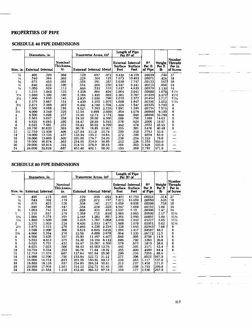
PROPERTIES OF PIPE
SCHEDULE 40 PIPE DIMENSIONS
lkansverse Areas, in? Length of Pipe
Per A2 of
2.717 3.652 5.793 7.575 9.109 10.790 14.61 18.97 28.55 40.48 53.6 63.0 78.0 105.0
L71.0 L23.0
11% 11% 8 8 8 8 8 8 8 8 - - - - - -
Diameters, in. Number
Nominal External Internal hickness, Surface Surface
in. 1 External Internal Metal 1 Feet Feet .068 .129 .057 .072 9.43.1 14.199
.229 .lo4 .125 7.073 10.493
ft3 Per ft
D f Pipe .00039 .00072 .00133 .00211 .00370 .00600 .01039 ,01414 .02330 .03325 .05134 .06866 .08840 .1389 .2006 .3552 .5476 .7763 .9354 ..223 ..555 ,926 1.793
Size, in, External Internal .405 .269
.364
.493 ,622 .824 1.049 1.380 1.610 2.067 2.469 3.068 3.548 4.026 5.047 6.065 7.981
Ya % Y8 % 3/4
1 1% 1 Yz 2 2% 3 3 '/z 4 5 6 8 10 12 14 16 18 20 24
.540
.675
.840 1.050 1.315 1.660 1.900 2.375 2.875 3.500 4.000 4.500 5.563 6.625 8.625 10.750 12.750 14.000 16.000 18.000
.088
.091
.lo9
.113
.133
.140
.145
.154
.203
.216
.226
.237 258 .280 .322 .365 .406 .437 .500 .563 .593 .687
,358 .554 .866 1.358 2.164 2.835 4.430 6.492 9.621 12.56 15.90 24.30 34.47 58.42 90.76 127.64 153.94 201.05 254.85 314.15 452.40
5.658 4.547 3.637 2.904 2.301 2.010 1.608 1.328 1.091 .954 .848 .686 ,576 .442 .355 .299 .272 .238 .212 .191 .159
7.747 6.141 4.635 3.641 2.767 2.372 1.847 1.547 1.245 1.076 .948 .756 .629 ,478 ,381 .318 .280 ,254 .226 .203 .169
.191 .167
.304 .250 ,533 .333 .864 .494 1.495 ,669 2.036 .799 3.355 1.075 4.788 1.704 7.393 2.228 9.886 2.680 12.73 3.174 20.00 4.300 28.89 5.581 50.02 8.399 78.85 11.90 0.020
1.938 3.125 5.000
~ ~~ ~~
111.9 15.74 135.3 18.64 176.7 24.35
6.874 20.000 18.814 24.000 22.626
224.0 30.85 278.0 36.15 402.1 50.30
SCHEDULE 80 PIPE DIMENSIONS -
ft3 Per ft if Pipe
Length of Pipe Per ft2 of
External Internal Surface Surface
Feet Feet
Diameters, in.
!xternal Internal
lkansverse Areas, in?
External Internal Metal
Vumber l'hreads Per in
Df Screw
Nominal Yhickness
in.
Weigh1 Per A
lb Size, in '/e Y4 3/8 % v4
1 1% 1 YZ 2 2% 3 3 Y2 4 5 6 8 10 12 14 16 18 20 24
.405 .215
.540 .302
.675 .423
.840 .546 1.050 .742 1.315 .957 1.660 1.278 1.900 1.500 2.375 1.939 2.875 2.323 3.500 2.900 4.000 3.364 4.500 3.826 5.563 4.813 6.625 5.761 8.625 7.625 10.750 9.564 12.750 11.376 14.000 12.500 16.000 14.314 18.000 16.126 20.000 17.938 24.000 21.564
.095
.119
.126
.147
.154
.179
.191 200 218 .276 .300 .318 ,337 .375 .432 ,500 .593 .687 .750 .843 .937 1.031 1.218
.129
.229
.358
.554
.866 1.358 2.164 2.835 4.430 6.492 9.621 12.56 15.90 24.30 34.47 58.42 90.76 127.64 153.94 201.05 254.85 314.15 452.40
,036 .09? .072 .157 .141 .217 .234 .32C .433 .433 .719 .636 1.283 .881 1.767 1.06E 2.953 1.475 4.238 2.254
9.431 17.750 7.073 12.650 5.658 9.030 4.547 7.000 3.637 5.15 2.904 3.995 2.301 2.990 2.010 2.542 1.608 1.970 1.328 1.645 1.091 1.317 .954 1.135 .848 .995 .686 .792 .576 .673 .442 .501 .355 .400 .299 .336 .272 .306 .238 ,263 .212 .237 ,191 .208 .159 ,177
.0002E
.0005C
.0009E ,00162 .003OC .005OC .00891 .0122i .02051 .0294? .04585 .06172 .0798 .1263 .1810 .3171 .4989 .7058 .8522 ,117 .418 .755 ,.536
,314 .53E .73E 1.00 1.47 2.17 3.00 3.65 5.02 7.66 10.3 12.5 14.9 20.8 28.6 43.4 64.4 88.6 107.0 137.0 171.0 209.0 297.0
27 18 18 14 14 11% 11y2 11% 11% 8 8 8 8 8 8 8 8 - - - - - -
~ ~ . _
6.605 3.01E 8.888 3.67E 11.497 4.405 18.194 6,112 26.067 8.30C 45.663 12.76 71.84 18.92 101.64 26.00 122.72 31.22 160.92 40.13 204.24 50.61 252.72 61.43 365.22 87.18
11 7

OVERALL HEAT TRANSFER COEFFICIENTS
Service Saturated Steam Alphabetical Free Forced *Clamp
Listing Convection Convection On Air 1-2 6-8 2.0
The “U” value, or overall heat transfer coefficient, represents the total BTU trans- mitted in one hour for each square foot of heat transfer surface at a temperature dif- ference of one degree Fahrenheit (BTUhr ftz F). “U” values are the arithmetical result of experiments, research, tests, prac- tice and operations in controlled installa- tions. Most “U” values are given for bare metal heat transfer surface in intimate con-
Water Free Forced “Clamp
Convection Convection On 2-3 5-8 2.0
tact with the product. In general, the “U” value is relatively high when a) the tem- perature of operation is high, b) there is mechanical circulation, c) surfaces are smooth and clean, and d) the viscosity of the fluid is low. In the table below, two “U” values, the low and high values normally experienced in general practice, are given for several of the more common heat trans- fer media/product applications.
~
Slurry, Light
Syrup
Sulphur, Molten
Sugar Solution
Tar Water
75-150 140-280 20-25 30-90 60-160 16-18 20-40 70-90 10-15 6-10 10-20 5-8 40-80 100-200 12-20 15-30 30-60 6-10 25-40 40-50 10-15 6-10 10-15 5-8 15-25 40-60 7-10 5-9 10-15 3-5 125-225 150-300 25-30 70-100 100-200 18-20
Selection of the “U” value should be on the conservative side and depends on the accuracy of *data describing the actual operating conditions and heat transfer characteristics of the product. “U” value estimates should be influenced by the fol-
lowing considerations: Is the fluid thick or viscous? Will it precipitate or cling to the heat transfer surface? What degree of foul- ing can be expected during the operating cycle?
118
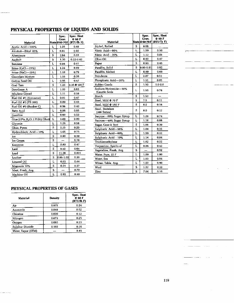
PHYSICAL PROPERTIES OF LIQUIDS AND SOLIDS
Asphalt Benzene Brine (CaC1-25%) Brine (NaC1-25%) Chocolate Mixture Cotton Seed Oil Coal Tars Dowtherm A
Spec. Spec. Heat
State @ BO-70F (BTUflb F) Material Acetic Acid-100%
S 1.30 0.22-0.40 L 0.84 0.41 L 1.24 0.69 L 1.19 0.79 L 1.15 0.39 L 0.95 0.47 S 1.20 0.356 105F L 1.00 0.63
Alcohol-Ethyl 95% I L I 0.81 I 0.60
Aluminum I S I 2.64 1 0.23
Ethylene Glycol Fuel Oil #1 (Kerosene) Fuel Oil #3 (PS 200) Fuel Oil #6 (Bunker C) Fatty Acid Gasoline Glue (2 Pts. H,O, 1 Pt Dry Glue) Glycerin
L 1.11 0.58 L 0.81 0.47 L 0.89 0.43 L 0.96 0.40 L 0.86 0.65 L 0.60 0.53 L 1.09 0.89 L 1.26 0.58
Material
Air
Spec. Spec. Heat
Material I State 1 6 ;i 60-70F 1 (BTUflb z: F) Nickel, Rolled Nitric Acid-95%
Density 8 60 F
0.075 0.24 (BTUflb F)
Nitric Acid-ZO% I L I 1.12 I 0.81
Olive Oil I L [ 0.93 I 0.47
Ammonia
Sugar, Cane & Beet Sulphuric Acid-98% 1 L I 1.84 I 0.35 Glass, Pyrex I S I 2.25 I 0.20
Hydrochloric Acid-10% I L I 1.05 I 0 75
0.048 0.52
~~
Ice I S I 0.90 1 0.50
Chlorine
Ice Cream Kerosene
Lead Leather Linseed Oil
0.020 0.12
Magnesia 10% I S I 0.21 I 0.27
Nitrogen 0.073
~
Sulphuric Acid-60% I L I 1.50 I 0.52
0.25
Sulphuric Acid-10%
Turpentine, Spirits of Vegetables, Fresh, Avg. 0.92
Oxygen
Water, Pure, 32 F I L I 1.00 I 1.00 Water, Sea I L I 1.03 I 0.94
0.083 0.23
Wines, Table, Avg. I L I 1.03 I 0.90
Sulphur Dioxide
Wool I S I 1.32 I 0.33 Zinc I S I 7.04 I 0.10 Meat, Fresh, Avg. I s 1 - I 0.70
Machine Oil 1 L I 0.93 I 0.40
0.183 0.16
PHYSICAL PROPERTIES OF GASES
Water, Vapor (STM) I -
I I S~ec.Heat
0.45
119

SPECIFIC HEATS OF FOODSTUFFS
Product
Apples Apricots, fresh Artichokes Aspara us Avocatos Bananas Barracuda Bass Beef, carcass Beef, flank Beef, loin Beef, rib Beef, round Beef, rump Beef, corned Beer Beets Blackberries Blueberries Brains Broccoli Brussels sprouts Butter Butterfish Cabbage Candy Carp Carrots Cauliflower
Cheese Cherries, sour Chicken, squab Chicken, broilers Chicken, fryers Chicken, hens Chicken, capons Clams, meat only Coconut, meat and milk Coconut, milk only Codfish Cod Roe Cowpeas, fresh Cowpeas, dry Crabs Crab apples Cranberries Cream Cucumber Currants Dandelion greens Dates Eels
:E3
Eggs Egg lant En8ve Figs, fresh Figs, dried Figs, candied Flounders Flour Fro s legs Garfic Gizzards Goose Gooseberry Granadilla Grapefruit Grapes Grape juice Guavas
Speci Btu pe
Above Freezing
.87
.88
.87
.94
.72
.80
.80
.82
.68
.56
.66
.67
.74
.62
.63
.89
.90
.87
.87
.84
.92
.88
.65
.77
.94
.93
.82
.91
.93
.94
.93
.65
.88
.80
.77
.74
.65
.88
.84
.68
.95
.86
.76
.73
.28
.84
.85
.90
.90
.97
.97
.88 2 0 .77 .76 .94 .95 .82 .39 .37 .86 .38 .88 .79 .78 .61 .86 .84 .91 .86 .82 .86
Heat, b per F
Below Freezing
.42
.43
.42
.45
.37
.40
.40
.41
.48
.32
.35
.36
.38
.34
.34
.43
.42
.42
.41
.44
.43
.34
.39
.45
.41
.44
.44
.45
.44
.43
.40
.39
.38
.35
.44
.41
.36
.45
.42
.39
.39
.22
.41
.41
.43
.38
.45
.45
.43
.007
.39
.40
.45
.45
.41
.26
.26
.42
.28
.44
.40
.39
.34
.42
.41
.44
.42
.41
.42
-
-
-
Product
Guinea hen Haddock Halibut Herring, smoked Horseradish, fresh Horseradish, prepared Ice cream Kale ~~~~~
Kidneys Kidney beans, dried Kohlrabi Kumquats Lamb, carcass Lamb, leg Lamb, rib cut Lamb, shoulder Lard Leeks Lemons Lemon juice Lettuce Lima beans Limes Lime juice Lobsters Loganberries Lo anberry juice Mifk, cow Mushrooms, fresh Mushrooms, dried Muskmelons Nectarines Nuts Olives, green Onions Onions, Welsh Oranges, fresh Orange juice Oysters Peaches, Georgia Peaches, N. Carolina Peaches, Maryland Peaches, New Jersey Peach juice, fresh Pears, Bartlett Pears, Beurre Bosc Pears, dried Peas, young Peas, medium Peas, old Peas, split Peppers, ripe Perch Persimmons Pheasant Pickerel Pickles, sweet Pickles, sour and dill Pickles, sweet mixed Pickles, sour mixed Pi 's feet, pickled Pi&e Pineapple, fresh Pineapple, sliced Pineapple juice Plums Pomegranate Pomp an o Por P o r r bacon Pork, ham Pork, loin
Speci Btu pr
Above Freezing
.75
.85
.80
.71
.79
.88
.74
.89
.81
.28
.92
.85
.73
.71
.61
.67
.54
.91
.91
.92
.96
.73
.89
.93
.82
.86
.91
.94
.93
.30
.94
.86
.28
.80
.90
.91
.90
.89
.84
.87
.89
.90
.91
.89
.89
.85
.39
.85
.81
.88
.28
.91
.82
.72
.75
.84
.82
.96
.78
.95
.50
.84
.88
.82
.90
.89
.85
.77
.81
.36
.62
.66
Heat, b per F
Below Freezing
.38
.42
.40
.37
.40
.43
.45
.43
.40
.23
.44
.41
.38
.37
.34
.35
.31
.44
.44
.44
.45
.38
.43
.44
.41
.42
.44
.47
.44
.23
.45
.42
.24
.40
.43
.44
.43
.43
.41
.42
.43
.43
.44
.43
.43
.41
.26
.41
.40
.43
.23
.44
.41
.37
.38
.41
.41
.45
.29
.45
.31
.41
.43
.41
.43
.43
.41
.39
.40
.25
.34
.35
~~ ~~ ~~ ~~~
-
~~~~ ~~~
120

SPECIFIC HEATS OF FOODSTUFFS
Product
Pork shoulder Pork, spareribs Pork, smoked ham Pork, salted Potatoes Prickly pears Prunes Pumukin Quinces Rabbit Radishes Raisins Raspberries, Black Raspberries, red Raspberry juice, black Reindeer Rhubarb Rutabagas Salmon Sapote Sauerkraut Sausage, beef and pork Sausage, bockwurst Sausage, bolo na Sausage, frankurt Sausage, salami Sardines Shrim S p a n i s mackerel Strawberries
Specil Btu pe
Above Freezing
.59
.62
.65
.31
.82
.91
.81
.92
.88
.76
.95
.39
.85
.89
.91
.73
.96
.91
.71
.73
.93
.56
.71
.71
.69
.45
.77
.83
.73
.95
Heat, 3 per F Below
Freezing .33 .34 .35 .24 .41 .43 .40 .44 .43 .39 .45 .26 .41 .43 .44 .37 .45 .44 .37 -37 .44 .32 .37 .37 .36 .28 .39 .41 .39 .45
Product
String beans Sturgeon, raw Sugar apple, fresh Sweet otatoes Swordgsh Terrapin Tomatoes Tomato juice Tongue, beef Tongue, calf Tongue, lamb Tongue, pork Tripe, beef Tripe, pickled Trout Tuna Turkey Turnips Turtle Veal, flank Veal, loin Veal, rib Veal, shank Veal, quarter Venison Watercress Watermelons Whitefish Wines Yams
Specil Btu pel
Above Freezing
.91
.83
.79
.75
.80
.80
.95
.95
.74
.79
.76
.74
.83
.89
.82
.76
.67
.93
.84 -65 .75 .73 .77 * 74 .78 .95 .94 .76 0.9 .78
~ Heat, b per F
Below Freezing
.44
.41
.39
.38
.40
.40
.45
.45
.38
.40
.38
.39
.41
.43
.41
.39
.35
.44
.41
.35
.38
.37
.39
.38
.39
.45
.45
.39
.39 -
121

PIPING SYMBOLS
BUSHING
SYMBOI ITEM SYMBOI
-D- UNION
CAP VALVE-CHECK, ANGLE
CROSS VALVE-CHECK, STRAIGHT
VALVE-COCK ELBOW-45" r" ELBOW-90" VALVE-DIAPHRAGM
8 d2 VALVE-FLOAT GAUGE-PRE S SURE
GAUGE-TEMPERATURE
ORIFICE
VALVE-GATE, ANGLE
VALVE-ISOLATION, GATE OR BALL +a-
@ PLUG-PIPE VALVE-GLOBE, ANGLE
VALVE-GLOBE, STRAIGHT PUMP-CENTRIFUGAL
AIR VENT REDUCER-CONCENTRIC
VACUUM BREAKER REDUCER-ECCENTRIC
STEAM TRAP
STRAINER
TEE
VALVE-QUICK OPENING
VALVE-SAFETY
VALVE-SOLENOID
122

!
I

. . . ,. . ~ . . . .~ ~ , . .. .~ .. . .... -. . . . . .. .. . . . .. " .
i

243 10M 192C . . ___ . . . . .. .--. .. . .. .- . -
Printed in U.S
Y A R W A Y C O R P O R A T I O N A SUBSIDIARY OF KEYSTONE INTERNATIONAL, INC.
Blue Bell. Pennsylvbnia 19422 Phone 215-825-2100 Telex 173115 Fax 215-825-1235
North American Regional Offices Los Angeles (Huntington Beach, CA) Houston (Houston, TX) Atlanta (Marietta, GA) Chicago (Wheaton. IL) Philadelphia (Spring House, PA) Toronto (Guelph, ONT)
Inquiries from other than North American Locations should be addressed to the International Department, Blue Bell PA