chapter steam flow meter selection
DESCRIPTION
steam flow meter selection presentationTRANSCRIPT

395
26Flowmeter Selection
Procedure
Introduction
Increased emphasis on tighter control and closer material balance is continuallyincreasing the number of flowmeter applications and putting increased emphasison flowmeter performance. As a result, flowmeter selection should be performedand documented in a logical manner in order to achieve the best flowmeter instal-lation, after considering technical and non-technical constraints.
Flowmeter Selection Procedure
Flowmeter selection is generally a process of elimination based on technical crite-ria. In this way, all flowmeter technologies are considered possible solutions untila specific reason is found to eliminate one or more of them from consideration.Once this has been done, other less tangible constraints can be used to establishthe final selection.
This procedure requires thorough familiarity with flowmetering in order toassess the various technical constraints.
Details of some technical and non-technical criteria and their applications tothe flowmeter selection procedure are presented in this section. The graphs anddata should be considered as typical and should be used as a guideline but not asabsolute references, because these parameters will change as technologies developand flowmeters improve.
Technical Criteria
There are a considerable number of technical criteria such as pressure, tempera-ture, specific gravity or density, viscosity, flow range, and the like. Beyond this,the flow characteristics of the meter are often Reynolds number-dependent, and

396 Industrial Flow Measurement
this fact may be used to further identify those flowmeter not likely to perform wellin a given application.
Figure 26-1 illustrates flowmeter constraints as a function of Reynolds num-ber for various flowmeter technologies. Other constraints such as pressure drop,sensitivity to solids accumulation, etc., which are not covered in detail by such agraph, illustrate the nature of the multiple constraints in flowmeter selection.
Figure 26-1. Liquid flow limits as a function of Reynolds number for various flowme-
ter technologies.

Chapter 26 – Flowmeter Selection Procedure 397
Solid lines in Figure 26-1 indicate ranges over which the flowmeter can becalibrated, while the dotted lines indicate ranges over which the flowmeter willoperate accurately. The minimum required Reynolds number at various flows foraccurate flowmeter operations is plotted and, unless otherwise indicated graphi-cally by an arrow, applicable Reynolds numbers are assumed to continue to infin-ity and applicable flows are assumed to be in excess of 1000 gpm. Wavy linesindicate a nonlinear operating region, which in the case of digital flowmeters isindicative of nonlinearities present before Reynolds number decreases sufficientlythat the flowmeter cease to operate and turns off.
Part of the flowmeter selection procedure for liquid service is to identify thevarious Reynolds number constraints for the given operating conditions. Range-ability, accuracy, sensitivity to Reynolds number, etc., should all be considered inidentifying those technologies that need no further consideration.
Operating Reynolds numbers can be plotted on the graph using worst caseextremes of viscosity and other physical properties. As flowmeter sizing mayrequire that the flowmeter be different from the pipe in which the fluid is flowing,Reynolds number may be plotted for the nominal pipe size, one size smaller thanthe nominal pipe size, and other pipe sizes determined by experience. Flowmetersthat cannot be calibrated to the desired full scale flow and whose minimum flow isgreater than the desired minimum flow should be eliminated, with the exceptionof positive displacement flowmeters operating at high viscosities (a condition thatcan decrease flowmeter range). These applications should be investigated on anindividual basis. Flowmeters that do not operate accurately in the Reynolds num-ber range graphed can also be eliminated.
As Reynolds number constraints are similar for liquid and gas applications,the procedure for gas service is identical to that for liquid service, with the excep-tion that Reynolds number should be plotted as a horizontal line and should beused only as a criterion for elimination of flowmeter technologies, as flow is diffi-cult to define due to the compressibility of gas.
Figure 26-2 shows the relationship between flowmeter rangeability and Rey-nolds number. The solid horizontal lined indicate the flow range over which eachflowmeter technology can be applied. The dotted lines indicate the flow rangeover which the flowmeter can measure but cannot be calibrated. Wavy lines indi-cated ranges of nonlinear flowmeter operation. Other technical criteria for consid-eration are included within columns on the graph. When the minimum andmaximum Reynolds numbers are plotted on this graph, technologies can be elimi-nated based upon Reynolds number and other technical criteria.
Non-Technical Criteria
There are a considerable number of non-technical criteria to be considered duringthe flowmeter selection process. These include, but are not limited to, cost (initialand installed), maintainability, spare parts availability, and vendor support afterinstallation.
Flowmeters not eliminated by technical criteria should be further evaluatedusing manufacturer literature and available operating experience. Selection can be

398 Industrial Flow Measurement
further refined by considering non-technical criteria such as cost, maintainability,delivery, etc. The final selection will generally embody a number of trade-offs butat the same time providing acceptable technical performance.
Applications
The flowmeter selection procedure presented above, while simple in concept,requires careful attention and evaluation of considerable detail. The applicationspresented below are not intended to show the best overall flowmeter for each ser-vice, but rather to illustrate the use of the flowmeter selection procedure on agiven set of operating conditions.
Figure 26-2. Technical criteria for various flowmeter technologies.
425°
400°
400°
Correlation>0.3 fps 315°C

Chapter 26 – Flowmeter Selection Procedure 399
Low Viscosity Liquids
Low viscosity liquids such as water and some light hydrocarbons comprise a greatmany flowmeter applications.
EXAMPLE 26-1
Problem: Using the flowmeter selection procedure, eliminate technologies that are not applicable to a flow of 150 gallons per minute of water in a 4-inch schedule 40 pipe when the viscosity is assume to be 1.0 cP and specific gravity is assumed to be 1.0. Accuracy requirements are ±1 percent of rate. The flowmeter must be mounted in a 60-inch straight section of pipe downstream of 2 elbows.
Solution: Reynolds number at maximum flow in the 4-in. pipe is given by
RD = (3160 × 150 gpm × 1.0)/(1.0 cP × 4.026 in.) = 117,735
Using an arbitrary 10:1 turndown for calculating Reynolds number, Reynolds number at 10 percent flow is 11,774 in the 4-inch pipe. Similarly, Reynolds number can be calculated for a 3-inch flowmeter installation as 154,498 and 15,450 for full scale and 10 percent of full scale, respectively. The operating Reynolds numbers are graphed as shown in Figure 26-3.
The graph illustrates that Reynolds number is not sufficiently large to operate venturi, flow nozzle, and low-loss flow tube technologies. Using the flowmeter selection procedure, the various technologies are listed and technical criteria are first used to eliminate those that are not applicable. Non-technical criteria can then be applied to eliminate still others. A summary of the above procedure is illustrated in Figure 26-4.
The remaining technologies can be considered individually to determine the optimum flowmeter, given the technical criteria of the application on hand. In this example, if the installed cost were of prime concern, a vortex shedding flowmeter might be selected. If energy consumption of the flowmeter is important, when pressure drop is limited by process constraints, or when the stream contains solids that might settle out, a magnetic flowmeter might be considered because of its obstructionless design. As can be seen from the above discussion, flowmeter selection must be tailored to each application. The flowmeter selection procedure presents a goal and aid in organizing the data used to arrive at the final flowmeter selection.

400 Industrial Flow Measurement
Figure 26-3. Operating Reynolds numbers (low viscosity liquid example).

Chapter 26 – Flowmeter Selection Procedure 401
Technical Non-technical
Differential pressure
Orifice Insufficient straight on
Elbow Insufficient accuracy
Flow nozzle RD too low X
Flow tube RD too low X
Laminar flow element RD too high X
Segmental wedge
Venturi RD too low X
V-cone
Magnetic
Mass
Coriolis Expensive
Hydraulic Out of range X
Oscillatory
Fluidic
Vortex shedding
Positive displacement
Helical Expensive, slippage
Nutating disc Out of range X
Oscillating piston Out of range X
Oval gear Expensive, slippage
Piston Out of range X
Rotary Expensive, slippage
Target Insufficient accuracy
Thermal Insufficient accuracy
Turbine Moving parts not preferred
Ultrasonic
Doppler Insufficient accuracy
Time of flight Expensive
Variable area Out of range X
Correlation Expensive
Insertion Hydraulic error too large X
Bypass Insufficient accuracy
Figure 26-4. Flowmeter selection summary (low viscosity liquid example).

402 Industrial Flow Measurement
Medium and High Viscosity Liquids
Medium and high viscosity liquids, which have viscosities greater than a fewcentipoise, are considered together due to the overlap that exists in some flowme-ter technologies because of sizing considerations. Extremely viscous materials aremuch more complex than the so-called Newtonian fluids. For example, asphalt,toothpaste, peanut butter, and other foodstuffs, or various types of organic andinorganic slurries often cannot be described by a single viscosity number andexhibit a variety of generally unfamiliar flow behaviors.
EXAMPLE 26-2
Problem: Using the flowmeter selection procedure, eliminate technologies that are not applicable to a flow of 30 gallons per minute of an organic liquid with a specific gravity of 1.17 in a 2-inch schedule 40 pipe when the viscosity can vary from 5 to 100 cP over the operating temperature range. Accuracy requirements are ±1 percent of rate.
Solution: The maximum value of Reynolds number at maximum flow and minimum viscosity in the 2-inch pipe is given by
RD = (3160 × 30 gpm × 1.17) / (5 cP × 2.067 in.) = 10,732
However, at maximum flow it can be as low as
RD = (3160 × 30 gpm × 1.17) / (100 cP × 2.067 in.) = 536.6
Values of Reynolds number at 10 percent of full scale flow are 1073 and 54, respectively. The operating Reynolds numbers are graphed as shown in Figure 26-5.
The graph illustrates that it is not possible to operate any of the flowmeters dependent upon Reynolds number over all operating conditions, even if the flowmeter size were reduced to 1 inch, which would effectively double Reynolds number. Elimination of flowmeter technologies is shown in Figure 26-6.
Remaining technologies include the mass flowmeter and various positive displacement flowmeters that can be considered individually to determine the optimum one, given the technical criteria of the application at hand. From this example, it can be seen how the flowmeter selection procedure eliminates many technologies when the proper criteria are considered.

Chapter 26 – Flowmeter Selection Procedure 403
Figure 26-5. Operating Reynolds numbers (medium and high viscosity liquid
example).

404 Industrial Flow Measurement
Technical Non-technical
Differential pressure
Orifice RD too low X
Elbow RD too low X
Flow nozzle RD too low X
Flow tube RD too low X
Laminar flow element RD too high X
Segmental wedge RD too low X
Venturi RD too low X
V-cone RD too low X
Magnetic Non-conductive X
Mass
Coriolis
Hydraulic Viscosity too high X
Oscillatory
Fluidic RD too low X
Vortex shedding RD too low X
Positive displacement
Helical
Nutating disc
Oscillating piston
Oval gear
Piston Out of range X
Rotary
Target RD too low X
Thermal Insufficient accuracy
Turbine RD too low X
Ultrasonic
Doppler RD too low X
Time of flight Operates in transition regime X
Variable area RD too low X
Correlation RD too low X
Insertion RD too low X
Bypass Not preferred in small pipe
Figure 26-6. Flowmeter selection summary (medium and high viscosity liquid
example).

Chapter 26 – Flowmeter Selection Procedure 405
EXAMPLE 26-3
Problem: Using the flowmeter selection procedure, eliminate technologies that are not applicable to a flow of 0.2 to 0.6 gallons per minute of an organic liquid in a 1-inch schedule 40 pipe when the viscosity can vary from 4 to 15 cP over the operating temperature range and specific gravity is 1.0. Accuracy requirement are ±1 percent of rate.
Solution: The maximum value of Reynolds number at maximum flow and minimum viscosity in the 1-inch pipe is given by
RD = (3160 × 0.6 gpm × 1.0) / (4 cP × 1.049 in.) = 452
However, at maximum flow it can be as low as
RD = (3160 × 0.6 gpm × 1.0) / (15 cP × 1.049 in.) = 452
At the minimum flow of 0.2 gpm, Reynolds numbers at minimum and maximum viscosity are 151 and 40, respectively. As the liquid velocity in the 1-inch pipe is not excessive, Reynolds number calculations can be performed for a ½-inch pipe size in an attempt to increase Reynolds number such that more flowmeters may be applicable. The maximum viscosity in the ½-inch pipe is given by
RD = (3160 × 0.6 gpm × 1.0) / (4 cP × 0.622 in.) = 762
However, at maximum flow it can be as low as
RD = (3160 × 0.6 gpm × 1.0) / (15 cP × 0.622 in.) = 203
Values of Reynolds number at 0.2 gpm are 254 and 68, respectively. The operating Reynolds numbers calculated above are graphed in Figure 26-7.
The graph illustrates that for a 1-inch flowmeter, it is not possible to operate any of the flowmeters dependent upon Reynolds number over all operating conditions. When the flowmeter is reduced to ½ inch, effectively doubling Reynolds number constraints are satisfied for an integral orifice plate, with the exception of extreme operating conditions of high viscosity at low flow conditions, which may only occur during short periods of time. This example illustrates how a change in flowmeter size can bring Reynolds number within the operating limits of a given flowmeter technology. Elimination of flowmeter technologies is shown in Figure 26-8.
Remaining technologies include various positive displacement flowmeters and the Coriolis mass flowmeter, which can be considered individually to determine the optimum one, given the non-technical criteria of the application at hand.

406 Industrial Flow Measurement
Figure 26-7. Operating Reynolds numbers (medium and high viscosity liquid
example).

Chapter 26 – Flowmeter Selection Procedure 407
Technical Non-technical
Differential pressure
Orifice Insufficient accuracy
Elbow RD too low X
Flow nozzle RD too low X
Flow tube RD too low X
Laminar flow element RD too low X
Segmental wedge RD too low X
Venturi RD too low X
V-cone RD too low X
Magnetic Non-conductive X
Mass
Coriolis
Hydraulic Pump not preferred
Oscillatory
Fluidic RD too low X
Vortex shedding RD too low X
Positive displacement
Helical Out of range @ operating viscosity X
Nutating disc
Oscillating piston
Oval gear
Piston
Rotary Out of range @ operating viscosity X
Target RD too low X
Thermal Insufficient accuracy
Turbine RD too low X
Ultrasonic
Doppler RD too low X
Time of flight Expensive
Variable area RD too low X
Correlation RD too low X
Insertion RD too low X
Bypass Not preferred
Figure 26-8. Flowmeter selection summary (medium and high viscosity liquid
example).

408 Industrial Flow Measurement
Gases
Operating gas density can vary significantly. Applications can often be dividedinto low, medium, and high-density categories. The operating density of the gas isdependent upon the combination of molecular weight of the gas and its operatingpressure and temperature.
Low-density applications present difficulties for flowmeters that utilize themomentum of the gas to operate the flowmeter, as the momentum may be insuffi-cient. Low-density applications are typified by most pure and process gases at lowpressure or vacuum, as well as light gases such as hydrogen at low and mediumpressure.
EXAMPLE 26-4
Problem: Use the flowmeter selection procedure to eliminate technologies that are not applicable to a 50-acfm flow of hydrogen in a 2-inch schedule 40 pipe where the operating pressure is nominally 5 psi at a nominal operating temperature of 80°F.
Solution: From physical property tables, the density of hydrogen at 14.7 psi and 68°F is 0.00523 pound per cubic foot. The density at nominal operating conditions can be calculated as
ρ = 0.00523 × [(460°F + 68°F) / 460°F + 80°F)] × [(14.7 psi + 5 psi)/14.7 psi]
= 0.00685 pound per cubic foot
Similarly, the viscosity is 0.009 cP. Reynolds number is calculated as
RD = (379 × 50 acfm × 0.00685 lb/ft3) / (0.009 cP × 2.067 in.) = 6980
which corresponds to a full-scale velocity of approximately 35.8 feet per second. The value of Reynolds number at 10 percent of full-scale flow is 698, which is relatively low for gas service and will play a significant role in flowmeter selection. The operating Reynolds numbers are graphed as a horizontal line as shown in Figure 26-9.
Technologies can be eliminated by using the technical and non-technical criteria, the results of which are summarized in Figure 26-10.
Remaining technologies include thermal profile and laminar flow elements, which can be evaluated individually to determine the optimum flowmeter for the application.

Chapter 26 – Flowmeter Selection Procedure 409
Figure 26-9. Operating Reynolds numbers (low density gas example).

410 Industrial Flow Measurement
Most flowmeter applications are in the medium density category, whichincludes most gases at medium pressures and light gases such as hydrogen at highpressures. Commonly measured gases include air, nitrogen, process gases, and thelike.
Technical Non-technical
Differential pressure
Orifice Requires pressure compensation
Elbow RD too low X
Flow nozzle RD too low X
Flow tube RD too low X
Laminar flow element
Segmental wedge
Venturi RD too low X
V-cone Requires pressure compensation
Magnetic Liquids only X
Mass
Coriolis Insufficient mass flow
Hydraulic Liquids only X
Oscillatory
Fluidic Liquids only X
Vortex shedding RD too low X
Positive displacement
Helical Liquids only X
Nutating disc Liquids only X
Oscillating piston Liquids only X
Oval gear Liquids only X
Piston Liquids only X
Rotary Liquids only X
Target RD too low X
Thermal
Turbine RD too low X
Ultrasonic
Doppler Liquids only X
Time of flight Liquids only X
Variable area Requires pressure compensation
Correlation RD too low X
Insertion RD too low X
Bypass Not preferred
Figure 26-10. Flowmeter selection summary (low density gas example).

Chapter 26 – Flowmeter Selection Procedure 411
EXAMPLE 26-5
Problem: Using the flowmeter selection procedure, eliminate technologies that are not applicable to a 500-scfm flow of air in a 3-inch schedule 40 pipe where the operating pressure is nominally 50 psi at a nominal operating temperature of 100°F.
Solution: From physical property tables, the density of air at 50 psi and 100°Fis 0.312 pound per cubic foot. Similarly the viscosity is 0.017 cP. The flow in actual cubic feet per minute can be calculated as:
Qacfm = 500 × [(460°F + 100°F)/(460°F + 60°F)] × [14.7 psi/(14.7psi + 50psi)]
= 122.4 acfm
Reynolds number can be calculated as
RD = (379 × 122.4 acfm × 0.312lb/ft3) / (0.017 cP × 3.068 in.) = 277,505
which corresponds to a full-scale velocity of approximately 39.8 feet per second. The value of Reynolds number at 10 percent of full-scale flow is 27,751, which is sufficiently high that many flowmeter technologies are not eliminated. The operating Reynolds numbers are graphed as a horizontal line as illustrated in Figure 26-11.
Technologies can be eliminated by using the technical and non-technical criteria, the results of which are summarized in Figure 26-12.
Remaining technologies include orifice plate and vortex shedding technologies, which can be evaluated to determine the optimum one for the application. Note that this application is relatively straight forward and virtually all technologies applicable to gas flow are acceptable; therefore, many non-technical criteria can be used to determine the order in which the remaining technologies can be evaluated. It should be noted that due to minimum velocity constraints, flowmeters that use the momentum of the fluid to operate may have to be less than 3 inches in size in order to achieve a reasonable turndown.
High-density gas applications involve the measurement of gases at high pressures. The commonly measured gases may be categorized with medium density flowmeter applications.

412 Industrial Flow Measurement
Figure 26-11. Operating Reynolds numbers (medium density gas example).

Chapter 26 – Flowmeter Selection Procedure 413
Technical Non-technical
Differential pressure
Orifice
Elbow Insufficient accuracy
Flow nozzle RD too low X
Flow tube RD too low X
Laminar flow element RD too high X
Segmental wedge
Venturi RD too low X
V-cone
Magnetic Liquids only X
Mass
Coriolis Expensive
Hydraulic Liquids only X
Oscillatory
Fluidic Liquids only X
Vortex shedding
Positive displacement
Helical Liquids only X
Nutating disc Liquids only X
Oscillating piston Liquids only X
Oval gear Liquids only X
Piston Liquids only X
Rotary Liquids only X
Target Insufficient accuracy
Thermal Insufficient accuracy
Turbine Moving parts
Ultrasonic
Doppler Liquids only X
Time of flight Liquids only X
Variable area Moving parts
Correlation Expensive
Insertion Hydraulic errors too large
Bypass Not preferred
Figure 26-12. Flowmeter selection summary (medium density gas example).

414 Industrial Flow Measurement
EXAMPLE 26-6
Problem: Use the flowmeter procedure to eliminate technologies that are not applicable to a 5000-scfm flow of nitrogen in a 2-inch schedule 80 pipe where the operating pressure is nominally 1000 psi at a nominal operating temperature 70°F.
Solution: From physical property tables, the density of nitrogen at standard conditions of 60°F and 14.7 psi is 0.0727 pound per cubic foot. Similarly, the viscosity at operating conditions is 0.033 cP. The density at 1000 psi is calculated to be
P = 0.0727 lb/ft3 × [(460°F + 60°F)/(460°F + 70°F)] × [(14.7 psi + 1000 psi)/14.7 psi ]
= 4.92 pounds per cubic foot
The flow in actual cubic feet per minute can be calculated as
Qacfm = 5000 scfm × [(460°F + 70°F)/(460°F + 60°F)] ×
[14.7 psi/(14.7 psi + 1000 psi)]
= 73.8 acfm
Reynolds number can be calculated as
RD = (379 × 73.8 acfm × 4.92 lb/ft3) / (0.033 cP × 1.939 in.) = 2,150,646
Which corresponds to a full-scale velocity of approximately 59.9 feet per second. Reynolds number can be graphed; however, it is sufficiently large that no technologies can be eliminated by Reynolds number constraints. They can, however, be eliminated by using the technical and non-technical criteria, the results of which are summarized in Figure 26-13.
Various technologies remain, including various differential pressure technologies, turbine flowmeters, and vortex shedding technology. Orifice plate technology is commonly applied in this type of application. However, other technologies such as vortex shedding and turbine flowmeters cannot be discounted in these applications as they offer equivalent performance in many applications. It should be noted that even though the operating pressure is 1000 psi, a 600-pound flanged flowmeter will handle this service because of the low operating temperature.

Chapter 26 – Flowmeter Selection Procedure 415
Technical Non-technical
Differential pressure
Orifice
Elbow Insufficient accuracy
Flow nozzle
Flow tube
Laminar flow element RD too high X
Segmental wedge
Venturi
V-cone
Magnetic Liquids only X
Mass
Coriolis
Hydraulic Liquids only X
Oscillatory
Fluidic Liquids only X
Vortex shedding
Positive displacement
Helical Liquids only X
Nutating disc Liquids only X
Oscillating piston Liquids only X
Oval gear Liquids only X
Piston Liquids only X
Rotary Liquids only X
Target Insufficient accuracy
Thermal Insufficient accuracy
Turbine
Ultrasonic
Doppler Liquids only X
Time of flight Liquids only X
Variable area Moving parts
Correlation Expensive
Insertion Not desired
Bypass Not desired
Figure 26-13. Flowmeter selection summary (high density gas example).

416 Industrial Flow Measurement
Steam
Steam is often classified as a gas flowmeter application. However, due to thequantity of flow measurements required in this service and the difficulties associ-ated with condensation, it is considered separately. Steam flow measurement isperformed under operating conditions that typically include both medium to highpressures and temperatures as well as various degrees of superheat. These rela-tively extreme operating conditions tend to eliminate many technologies.
EXAMPLE 26-7
Problem: Using the flowmeter selection procedure, eliminate technologies that are not applicable to a 0 to 60,000-pound per hour flow of 225-pound saturated steam in a 6-inch schedule 80 pipe.
Solution: From steam tables, the 225-psi saturated steam has an operating temperature of 397°F and an operating density of 0.521 pound per cubic foot. Similarly, the viscosity at operating conditions is 0.016 cP. The flow in actual cubic feet per minute can be calculated as
Qacfm = (60,00 lbs/hr) × (hr/60 min) × (ft3/0.521 lb/ ft3/0.521 lb/ ft3)
= 1919.4 acfm
Reynolds number can be calculated as:
RD = (379 × 1919.4 acfm × 0.521 lb/ft3) / (0.016 cP × 5.761 in.) = 4,111,730
which corresponds to a full-scale velocity of approximately 159.5 × (6.065/5.761)2, or 176.8 feet per second. Reynolds number is sufficiently large that no technologies are eliminated by Reynolds number constraints. Technologies can be eliminated by using the technical and non-technical criteria, the results of which are summarized in Figure 26-14.
Various technologies remain, including various differential pressure, vortex shedding, and insertion flowmeter technologies. Orifice plate and vortex shedding, and insertion flowmeter technologies are the economical choices, although certain insertion technologies may also be economical. However, errors inherent in centerline-positioned insertion flowmeters should be taken into account.
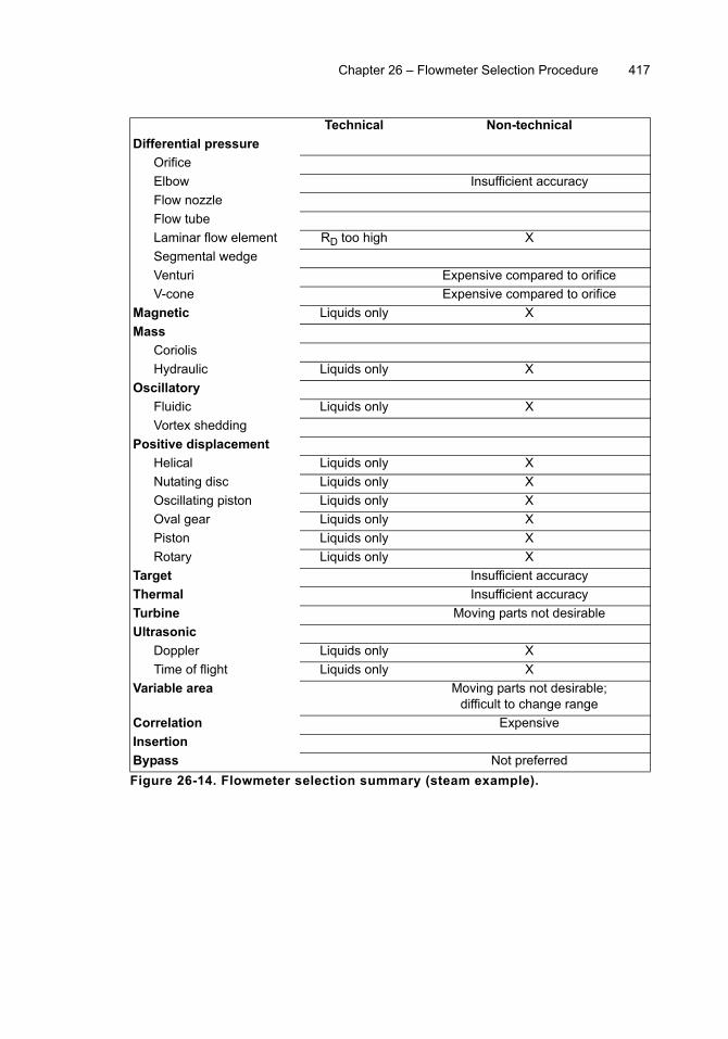
Chapter 26 – Flowmeter Selection Procedure 417
Technical Non-technical
Differential pressure
Orifice
Elbow Insufficient accuracy
Flow nozzle
Flow tube
Laminar flow element RD too high X
Segmental wedge
Venturi Expensive compared to orifice
V-cone Expensive compared to orifice
Magnetic Liquids only X
Mass
Coriolis
Hydraulic Liquids only X
Oscillatory
Fluidic Liquids only X
Vortex shedding
Positive displacement
Helical Liquids only X
Nutating disc Liquids only X
Oscillating piston Liquids only X
Oval gear Liquids only X
Piston Liquids only X
Rotary Liquids only X
Target Insufficient accuracy
Thermal Insufficient accuracy
Turbine Moving parts not desirable
Ultrasonic
Doppler Liquids only X
Time of flight Liquids only X
Variable area Moving parts not desirable; difficult to change range
Correlation Expensive
Insertion
Bypass Not preferred
Figure 26-14. Flowmeter selection summary (steam example).

418 Industrial Flow Measurement
Large Pipe
Flowmeters applied to large pipes merit special attention because of the complex-ities of piping layout and the difficulties of applying flowmeter technology tolarge piping.
EXAMPLE 26-8
Problem: Using the flowmeter selection procedure, eliminate technologies that are not applicable to a 0 to 10,000 gallons per minute flow of water flowing in a 24-inch, ½-inch wall pipe at 100°F.
Solution: From property tables, the operating specific gravity of water is 0.994 and the operating viscosity is 0.67 cP. Reynolds number can be calculated as
RD = (3160 × 10,000 gpm × 0.994) / (0. 67 cP × 23.0 in.) = 2,038,313
Reynolds number is sufficiently high that no technologies will be eliminated by graphing Reynolds number. A summary of the technical and non-technical criteria used to eliminate technologies is presented in Figure 26-15.
Various technologies remain, including those of differential pressure (which generally exhibit significant energy losses at such high flows) and insertion flowmeters (which are typically very economical in large pipe diameter applications). Bypass flowmeters can also be applied.

Chapter 26 – Flowmeter Selection Procedure 419
Technical Non-technical
Differential pressure
Orifice Large energy loss
Elbow Insufficient accuracy
Flow nozzle
Flow tube
Laminar flow element RD too high X
Segmental wedge Out of range X
Venturi
V-cone Large energy loss
Magnetic Expensive
Mass
Coriolis Out of range X
Hydraulic Out of range X
Oscillatory
Fluidic Out of range X
Vortex shedding Out of range X
Positive displacement
Helical Out of range X
Nutating disc Out of range X
Oscillating piston Out of range X
Oval gear Out of range X
Piston Out of range X
Rotary Out of range X
Target Out of range X
Thermal Out of range X
Turbine Expensive
Ultrasonic
Doppler Insufficient accuracy
Time of flight Expensive
Variable area Out of range X
Correlation Expensive
Insertion
Bypass
Figure 26-15. Flowmeter selection summary (large pipe example).

420 Industrial Flow Measurement
EXERCISES
26.1 Use the flowmeter selection procedure to eliminate technologies that arenot applicable to a flow of 1000 gallons per minute of a liquid in an 8-inchschedule 40 pipe when the viscosity and specific gravity are assumed tobe 1.4 cP and 0.89, respectively. Accuracy requirements are 1 percent ofrate.
Technical Non-technical
Differential pressure
Orifice
Elbow
Flow nozzle
Flow tube
Laminar flow element
Segmental wedge
Venturi
V-cone
Magnetic
Mass
Coriolis
Hydraulic
Oscillatory
Fluidic
Vortex shedding
Positive displacement
Helical
Nutating disc
Oscillating piston
Oval gear
Piston
Rotary
Target
Thermal
Turbine
Ultrasonic
Doppler
Time of flight
Variable area
Correlation
Insertion
Bypass
Figure Q1. Flowmeter selection summary.

Chapter 26 – Flowmeter Selection Procedure 421
26.2 Use the flowmeter selection procedure to eliminate technologies that arenot applicable to a flow of 15 gallons per minute of an organic liquid in a2-inch schedule 40 pipe when the viscosity can vary from 1000 to 1500cP over the operating temperature range and specific gravity is 1.21.Accuracy requirements are ±1 percent of rate.
Technical Non-technical
Differential pressure
Orifice
Elbow
Flow nozzle
Flow tube
Laminar flow element
Segmental wedge
Venturi
V-cone
Magnetic
Mass
Coriolis
Hydraulic
Oscillatory
Fluidic
Vortex shedding
Positive displacement
Helical
Nutating disc
Oscillating piston
Oval gear
Piston
Rotary
Target
Thermal
Turbine
Ultrasonic
Doppler
Time of flight
Variable area
Correlation
Insertion
Bypass
Figure Q2. Flowmeter selection summary.

422 Industrial Flow Measurement
26.3 Use the flowmeter selection procedure to eliminate technologies that arenot applicable to a 300 scfm flow of an ideal gas in a 2-inch schedule 40pipe where the operating pressure in nominally 100 psi at a nominaloperating temperature of 40°F when the density at standard conditions is0.110 pound per cubic foot and the operating viscosity is 0.015 cP.
Technical Non-technical
Differential pressure
Orifice
Elbow
Flow nozzle
Flow tube
Laminar flow element
Segmental wedge
Venturi
V-cone
Magnetic
Mass
Coriolis
Hydraulic
Oscillatory
Fluidic
Vortex shedding
Positive displacement
Helical
Nutating disc
Oscillating piston
Oval gear
Piston
Rotary
Target
Thermal
Turbine
Ultrasonic
Doppler
Time of flight
Variable area
Correlation
Insertion
Bypass
Figure Q3. Flowmeter selection summary.

Chapter 26 – Flowmeter Selection Procedure 423
26.4 Use the flowmeter selection procedure to eliminate technologies that arenot applicable to a 0 to 2000 pound per hour flow 225-pound saturatedsteam in a 2-inch schedule 80 pipe.
Technical Non-technical
Differential pressure
Orifice
Elbow
Flow nozzle
Flow tube
Laminar flow element
Segmental wedge
Venturi
V-cone
Magnetic
Mass
Coriolis
Hydraulic
Oscillatory
Fluidic
Vortex shedding
Positive displacement
Helical
Nutating disc
Oscillating piston
Oval gear
Piston
Rotary
Target
Thermal
Turbine
Ultrasonic
Doppler
Time of flight
Variable area
Correlation
Insertion
Bypass
Figure Q4. Flowmeter selection summary.