indoor and outdoor microclimate analysis of green ... issues but to integrate them into the...
TRANSCRIPT

1
Indoor and Outdoor Microclimate Analysis of Green Buildings
Grant R. Rawcliffe, B.Eng.1 Ray Sinclair, Ph.D.2
1 Project Manager, Rowan Williams Davies & Irwin Inc., Phone: 1-519-823-1311 Ext.2369. Fax: 1-519-823-1316. E-mail: [email protected]
2 Principal / Project Director, Rowan Williams Davies & Irwin Inc., Phone: 1-519-823-1311Ext. 2300. Fax: 1-519-823-1316. E-mail: [email protected]
INTRODUCTIONArchitects and engineers have always been aware of the influence of the outdoor microclimate onbuildings. Typical issues are: the building�s ability to withstand forces due to wind and snow; solargains due to sunlight or noise; and vibration due to nearby sources. With the strengtheningemergence of Green Building concepts, designers are being challenged to not only consider outdoormicroclimate issues but to integrate them into the fundamental design and operation of the building.Similarly, Green Building concepts are raising the quality of the indoor microclimate to account foroccupant comfort, satisfaction, and productivity.
This paper outlines the influence that microclimate issues have on various components of highperformance buildings and presents strategies for enhancing building performance by ensuring thatthe building design is effective in addressing these issues.
KEY ISSUESA number of the issues related to the outdoor and indoor microclimate are outlined below. Althoughnot all of the issues are specific to Green Buildings, they are relevant to the creation of higherperformance buildings, which is the intention of sustainable design:
1. Wind - Cladding and structural loads, pedestrian level comfort,natural ventilation, energy production.
2. Solar - Daylighting, solar heating, cooling load reduction, energyproduction and conservation.
3. Temperature and Humidity - Natural ventilation, thermal comfort.4. Noise, Vibration & Acoustics - Sound and vibration isolation (external and internal),
performance of acoustically sensitive spaces.5. Air Quality - Exhaust re-entrainment, ambient pollution levels.6. Air Distribution - Thermal comfort, indoor air quality, condensation control,
smoke management.7. Snow - Structural loads, sliding ice and snow.

2
Many of these issues are inextricably linked to each other, to the construction and operating costs ofthe building and to the performance of the building (comfort, energy, safety, environmental impact).
THE RISKS AND BENEFITS OF MICROCLIMATE ISSUESSome of the potential risks that microclimate issues present to building designers are outlined in thefollowing table. The table also includes some of the potential benefits associated with addressingthese issues early in the building design:
Table 1 Potential Risks and BenefitsPotential Risks Potential Benefits
� Failure to achieve design objectives� High operating costs� Poor occupant health and satisfaction� Potential retrofit costs� Mold/mildew and Sick Building
Syndrome� Contamination of adjacent sites� High noise levels and poor acoustics� Potential for loss of life from fire� Higher snow management costs� Loss of use of facilities� Repair costs for building damage
� Lower construction costs� Lower operating costs� Improve occupant health, safety and comfort� Smoke management systems that perform as
intended� Achieve project objectives
ADDRESSING MICROCLIMATE ISSUESOnce the microclimate issues relevant to the project have been identified, the next question is �howdo we address these issues and determine their impact on the building design?�. There are a numberof different approaches available to designers including �Rules of Thumb�, building codes, designreviews and/or detailed engineering studies. Each of these approaches varies in its level of effort,cost, risk and accuracy.
The building industry is very familiar with the use of �Rules of Thumb� and building codes and relieson these approaches for many aspects of building design. These are attractive due to the relativelylow level of effort and, therefore, cost. However, these approaches tend to be applicable for standardbuilding shapes, orientations, and geographical locations. They typically provide conservative worstcase estimates of design loads or challenges to the building design. This conservatism can causeunnecessary capital cost increases and, in many instances, particularly with high performancebuildings, this low level of analysis results in a high level of uncertainty which increases the risk ofnot achieving the project objectives. As well, for more unique buildings and sites, code typecalculations can fail to adequately predict impacts. In short, they really do not provide guidance onhow to achieve an optimal design.

3
TOOLS FOR PERFORMING DETAILED MICROCLIMATE ENGINEERING STUDIES
Introduction There are a large number of tools available to designers for performing detailed microclimateengineering studies. These tools typically fall into the two broad categories of Numerical Modelingand Physical Modeling.
Numerical ModelingThis approach uses computers and specialized software to create a numerical representation of theproject, to apply appropriate microclimate conditions to the model (e.g., historical weather data forthe site) and to solve a series of mathematical equations to determine the influence of themicroclimate on the building�s performance. Expertise and practical experience is required toestablish acceptable inputs, understand the simplifications and limitations of the methods, and tointerpret the results. The most elaborate numerical modeling is Computational Fluid Dynamics (CFD)computer simulation.
For building designers, CFD is a computer simulation of the flows of air and heat. The method usesa CAD model of a room (e.g., atrium) which is then divided into a grid of several hundred thousandcontrol volumes over which the fundamental equations for the conservation of mass, momentum andthermal energy are solved, together with a mathematical model that predicts the effects of turbulence.Boundary conditions are specified to indicate the quantities of supply and return air and thedistribution of heat loads. The CFD model is run to iteratively solve the equations to a specifiedtolerance. The predicted air velocity and temperature patterns are displayed with easily understood3D color graphics. The typical effort of man-hours to setup and run a model is several days to a fewweeks and each run of the model takes several hours to a few days of computer time on the fastestdesktop computers.
There are many technical issues that can affect the quality of the results from a CFD simulation. Thefollowing are some of the key issues for modeling ventilation systems in buildings which designersshould expect the CFD analysts to understand:
� Simplification technique for the representation of supply diffusers, yet still achieving goodaccuracy.
� Grid resolution around supply diffuser jets, fire plumes, smoke layers, hot surfaces, etc.� Direct solar loads - distribution, intensity, amount absorbed and conducted through surfaces.� Wall and ceiling temperature boundary conditions - constant temperature, constant heat flux,
or adiabatic (insulated) walls.� Grid resolution around windows for draft or condensation predictions.� Steady state versus unsteady flow simulations - many flows with natural convection
(buoyancy and thermal stratification) need unsteady solutions.� Selection of turbulence model - e.g., the standard k- , turbulence model does not predict
swirling flows well, and for some flow situations empirical coefficients need adjustment.

4
Figure 1 Incorrect Modeling Figure 2 Correct Modeling
The following is a contrived illustration of the supply diffuser modeling issue mentioned above (firstpoint). The situation is a room with multi-slot supply air diffusers. In Figure 1 the multiple slots arerepresented as a single slot of equivalent area to the multiple slots. This ensures a correct supply airvelocity, but the single jet does not account for the extra entrainment that occurs with multiple jets.In Figure 2 the diffuser is represented as the same single slot but the momentum of the jet has beenadjusted, based on appropriate calibration data, to account for the additional entrainment resultingfrom the multiple jets. Figure 1 shows the incorrect prediction of the throw of the supply air which,when interpreted by the design team, would likely suggest that the design needs to change to fix apredicted draft problem. This would not be a valid conclusion since the correct result shown inFigure 2 demonstrates satisfactory air distribution and no draft concerns.
Physical ModelingEven with the expanding capabilities of numerical modeling, there are still instances where theapproximations and simplifications inherent in numerical modeling techniques limit their applicability.This is prominent with wind-related issues for projects that have either complex shapes orsurroundings (topographic or structures) that make it difficult to predict the dynamics of the externalair flows on the site. Even for CFD there can be difficulties with the broad range of length and timescales of the external wind flows and the limitations of mathematical equations predicting the effectsof turbulence within the roughness elements (buildings) of the atmospheric boundary layer.
Physical modeling of external microclimate issues, such as wind and snow, can be achieved throughthe creation of a physical scale model of the study building and surrounding topography andstructures. This model can then be placed in a wind tunnel (Figure 3) or water flume (Figure 4) that,through appropriate scaling of upwind roughness, approximates the wind conditions at the site. Themajor advantages of using scale models to predict external wind lie in their ability to represent theturbulent and unsteady nature of the flows. As well, the tests are cost-effective. Numerous winddirections and speeds or different configurations of the building or surroundings can be tested in atimely manner.
Wind tunnel modeling of external flows is most applicable to studies such as cladding and structural
5
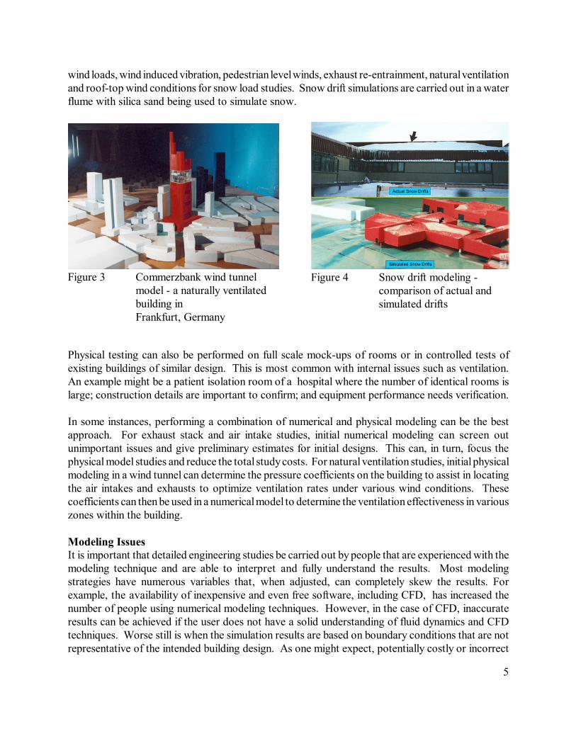
Figure 3 Commerzbank wind tunnelmodel - a naturally ventilatedbuilding in Frankfurt, Germany
Figure 4 Snow drift modeling -comparison of actual andsimulated drifts
wind loads, wind induced vibration, pedestrian level winds, exhaust re-entrainment, natural ventilationand roof-top wind conditions for snow load studies. Snow drift simulations are carried out in a waterflume with silica sand being used to simulate snow.
Physical testing can also be performed on full scale mock-ups of rooms or in controlled tests ofexisting buildings of similar design. This is most common with internal issues such as ventilation.An example might be a patient isolation room of a hospital where the number of identical rooms islarge; construction details are important to confirm; and equipment performance needs verification.
In some instances, performing a combination of numerical and physical modeling can be the bestapproach. For exhaust stack and air intake studies, initial numerical modeling can screen outunimportant issues and give preliminary estimates for initial designs. This can, in turn, focus thephysical model studies and reduce the total study costs. For natural ventilation studies, initial physicalmodeling in a wind tunnel can determine the pressure coefficients on the building to assist in locatingthe air intakes and exhausts to optimize ventilation rates under various wind conditions. Thesecoefficients can then be used in a numerical model to determine the ventilation effectiveness in variouszones within the building.
Modeling IssuesIt is important that detailed engineering studies be carried out by people that are experienced with themodeling technique and are able to interpret and fully understand the results. Most modelingstrategies have numerous variables that, when adjusted, can completely skew the results. Forexample, the availability of inexpensive and even free software, including CFD, has increased thenumber of people using numerical modeling techniques. However, in the case of CFD, inaccurateresults can be achieved if the user does not have a solid understanding of fluid dynamics and CFDtechniques. Worse still is when the simulation results are based on boundary conditions that are notrepresentative of the intended building design. As one might expect, potentially costly or incorrect

6
decisions can be made.
ACHIEVING MICROCLIMATE OBJECTIVES
Start EarlySite selection, building orientation and building massing are three factors that are usually determinedearly in the concept development phase of a building�s design. These are influential factors in abuilding�s ability to address the majority of the microclimate issues this paper discusses.
A review of the historical meteorological data for the site provides insight into its climate throughoutthe year. This information is valuable in assessing the building�s ability to employ Green Buildingstrategies such as natural ventilation. Similarly, determining the solar inclination at the site can helpdetermine the orientation of the building to maximize the effectiveness of day lighting, thermal storageand solar gain reduction.
Taking background measurements of noise, vibration and air quality and/or performing numericalmodeling of these issues provides designers with guidance on measures required to ensure occupantcomfort and building performance, both for the current site status and for future development ofsurrounding sites.
Pedestrian Level WindPedestrian comfort around the building can also be assessed early in the design through a review ofwind climate, the building mass and orientation, site topography and surrounding buildings. Buildingfeatures, such as a podium, can be incorporated into the building design to reduce wind impacts atground level. For example, RWDI provided input on ground level winds for the initial World TradeCenter design concepts for the majority of the competitors in the design competition. The adviceaddressed issues such as the angling of facades to ensure winds were not deflected down towardspedestrians.
SnowDepending on the site�s geographical location, snow can also be a microclimate issue that can impacta building�s performance. Snow drifting can not only threaten a building�s structure but can alsocause havoc with pedestrian and vehicular access to the building, if not considered early. A reviewof the building design and site layout by a specialist in snow issues can identify potential concernsearly to allow changes which could reduce the impact of snow drifting on the building environment.
� Large upper roofs will have higher step loads due to the increased source of snow available toscour and accumulate in the step to the lower roof. Installing parapets on the upper roofs willreduce step loads by trapping snow that would normally be scoured off and accumulate in thestep to the lower roof.
� Provision of wind deflectors above building entrances directs airflow to scour snow and keepentrances clear.
� Preliminary estimates of wind and snow loads on long span structures by experts can providefeedback to the structural design team on loadings that are likely to be greater or less than code

7
to allow for the development of an appropriate structural scheme.
EnergyEnergy conservation is one of the defining factors in sustainable design and is also one of the majorcontributors to reduced operating costs. This is a prime motivator for building operators anddesigners to incorporate sustainable concepts in their high performance buildings.
There are numerous strategies to conserve energy within a building and also numerous tools forassessing a building�s energy usage. This paper does not expand further on energy conservation butrather focuses on issues related to the microclimate that can, in some cases, significantly influenceenergy usage.
SolarOne of the primary factors influencing energy efficiency is solar design. Passive solar systems utilizethe various components of the building (walls, glazing, floor, roof) to provide space heating, coolingload reduction, natural ventilation, water heating, and daylighting. However, these solarmanagement strategies can sometimes have conflicting requirements that must be integrated in thedesign of the passive solar systems (e.g., daylighting is maximized by using light colored surfaceswhile solar heating is maximized by using darker surfaces).
The City of Austin�s Green Building Program Sustainable Building Sourcebook and The U.S.Department of Energy Office of Energy Efficiency and Renewable Energy�s Building TechnologiesProgram provide guidance to building designers on effective passive solar design. Such guidanceincludes:
� Appropriate spaces. Spaces where occupancy time is lengthy (offices) can overheat andexperience glare from a direct solar system. Lobbies and atria are more suited for this type ofsystem.
� Maximize solar heating. Elongate building along East-West axis with majority of glazing facingwithin 15 degrees of South. Utilize thermal mass of building components, floors, walls, roof fordirect or indirect thermal storage. The surface area of mass exposed to direct sunlight shouldbe 9 times the area of the glazing. Limit thermal mass materials to 6 inches thick and leave asbare as possible. For every square foot of south glass, use 150 pounds of masonry. Provideexternal insulation on walls to limit radiation to exterior from thermal mass elements.
� Minimize cooling load. Select glazing types and shading strategies to restrict solar gains at timeswhen solar heating is not required.

8
� Maximize daylighting, A standard window can produce useful illumination to a depth of about1.5 times the height of the window and up to 2 times with the use of lightshelves or otherreflector systems. Use high reflectance paint on ceilings and walls opposite windows. Angleceilings toward windows. Design for an Effective Aperture (product of visible transmittanceand window-to-wall ratio) of at least 0.2 to 0.3. Utilize toplighting strategies such as skylights,roof top monitors, celestory windows and sawtooth roof. Use open plan office layouts orinternal glazing.
• Minimize glare. Limit East/West glazing to avoid glare from morning and evening sun.
Advanced modeling of a passive solar system to assess daylighting, cooling load reduction, glareand solar heating can be performed either physically or via computer. Although physical modelscan be effective in providing a clear assessment of daylighting performance, they are limited in theirquantitative output and ability to address the other factors of a passive solar system. Advancedcomputer analysis is becoming increasingly popular with software packages such as Lumen-Micro,Radiance, Lightscape, EcoTect, TRNSYS, ADELINE, DOE-2.
Air DistributionThe effective distribution of air inside buildings under normal and emergency operating conditionsis essential to achieving occupant health, comfort and safety as well as managing buildingdeterioration from condensation, mold and mildew. Building codes provide minimum rates for thesupply of outside air under normal operating conditions but do not typically provide any guidance onthe distribution of supply air. Under fire conditions they are more specific in that they limit make-upair velocities for smoke management systems to 200 fpm but again provide little or no guidance onwhere make-up air intakes should be located.
For large complex spaces (auditoria, conference rooms, museums, atria, stadiums), innovativeventilation systems or highly sensitive rooms (rooms with sensitive equipment, operating theaters,clean rooms), it is important that a higher level of design is undertaken to refine and prove the designprior to construction. This would either be in the form of a Design Review or a Detailed EngineeringStudy.
CFD modeling can predict the performance of the proposed ventilation system. The output from theCFD modeling includes air speed and temperature. This information can illustrate the level of thermalstratification, draft, condensation potential, thermal comfort of occupants and distribution of solarloads.
Under fire conditions large multi-level atrium spaces can cause large volumes of smoke to beproduced due to the height that the smoke rises to the ceiling and the opportunity for a balcony spillplume to occur. Thermal stratification can also create an artificial ceiling at a lower level that couldresult in unforeseen safety concerns. Code calculated exhaust rates of 400,000 to 1,000,000 cfm arenot uncommon for these types of spaces. These high exhaust rates are usually not practical toimplement and therefore more advanced analysis is warranted to determine a safe design that isbuildable, Sinclair (2001).

9
Figure 5 Atrium Smoke CFD Simulation
CFD modeling can be used to simulate a fire scenario at one or more locations and track the smokeplume through time to determine its impact on each level. If a failure is predicted with the smokemanagement system (i.e., smoke layer descends below the target criteria) then changes can be madeto the model to refine the design Such changes may include redistribution of the make-up-airsupply, adjusting the location and capacity of the exhaust system, or installation of smoke barriers.Engineering reports that include the CFD model results are usually accepted by the authority havingjurisdiction to prove satisfactory performance of designs that provide equivalent safety, even ifsmoke exhaust rates may be below simple code calculations. The designer should, however, haveconfidence that the smoke management consultant has a verified methodology for CFD modelanalysis. Sometimes less experienced practitioners will predict a successful design by incorrectlyunder-predicting the smoke plume entrainment.
Natural VentilationIncreasing in popularity, natural ventilation is a ‘hot topic’ in the Green Building community.Promising higher indoor air quality and reduced capital and operating costs, this Green Buildingstrategy is very tempting for building designers and owners. But it has risks.
Some of the questions and concerns associated with using natural ventilation include: the reliabilityof outdoor ventilation rates, the distribution of outdoor air within the building, the control ofmoisture, building pressurization concerns and entry of polluted air from outdoors without filtration,noise impacts, and acoustics.
Additionally, Kronvall et al. (1998) identifies some of the factors that are beneficial to naturalventilation performance. These include higher buildings, airtight buildings, well insulated

10
envelopes, high thermal mass, large area of (adjustable) facade vents, limited internal heat loads,night ventilation, minimized window area, active use of windows and effective solar shading.
There are three basic natural ventilation strategies that can either be used exclusively, incombination with each other, or in combination with mechanical ventilation (a hybrid system). Thethree basic natural ventilation strategies are [Emmerich et al. (2001)]:
1. Wind driven cross ventilation - ventilation openings, typically windows, on opposite sides ofan enclosed space. Requires a significant difference in wind pressure between the inlet andoutlet openings and a minimal internal resistance to flow. As well, McCreary (2001)recommends locating naturally ventilated kitchens, laundries and bathrooms on the leeward sideof the building to avert hot humid air from being re-entrained into other spaces.
2. Buoyancy driven stack ventilation - relies on density differences to draw cool, outdoor air inat low ventilation openings and exhaust warm, indoor air at high ventilation openings.Typically uses chimneys or atria to generate sufficient buoyancy forces to achieve the requiredflow. Wind will also induce pressure distributions on the building envelope that will also actto drive airflow and may well be more important than buoyancy effects. Successful designswill seek ways to take full advantage of both.
3. Single sided ventilation - ventilation airflow is driven by room-scale buoyancy effects, smalldifferences in envelope wind pressures, and/or turbulence. Consequently, driving forces forsingle-sided ventilation tend to be relatively small and highly variable. This is the leastattractive solution but can serve single offices.
For wind driven flows, some natural ventilation designers will design for the prevailing wind speedsand directions for a site. While often a good starting point, this approach can be limited for manysites since prevailing winds may represent less than 50% of the wind conditions. As well it does notaccount for the influences that existing or future surrounding structures will have on the wind actingon the proposed building.
The most accurate way to gather this information is to build a physical scale model of the buildingand surroundings and test it in a wind tunnel. Pressure coefficients are determined at various pointson the building exterior for numerous wind directions. The pressure coefficients can then beconverted to external pressures for any wind velocity. Pressure differences across hydraulic(ventilation air) pathways through the building can be estimated and used to predict bulk ventilationrates. Then using the local meteorological data, further analysis can predict the percent of timevarious ventilation rates are achieved under various temperature, humidity and building heat loads.
Although wind tunnel modeling is effective for determining bulk ventilation rates it is rarely used fordetermining flows through multiple zones within the building. This is most effectively achievedthrough the use of a multi-zone computer modeling program such as CONTAMW. As well, CFDcan predict mechanical, wind-driven and thermally-driven flows within a single zone or multiplezones. Pressure coefficients from wind tunnel data can be incorporated as part of the boundaryconditions to further increase the accuracy of the results and evaluate the system’s performanceunder various wind conditions.

11
Figure 6 CFD Computer Model Figure 7 Temperature Profiles
Figures 6 and 7 illustrate a ventilation study for the atrium of the International Center for PossibilityThinking at the Crystal Cathedral campus in Garden Grove, California. This is a 60,000 square footfacility that is ventilated using a combination of natural and mechanical ventilation. The CFDsimulations were able to predict the air flow distribution and temperatures within the main lobbyand atrium and the level of stratification in the ‘chimneys’. Based on the results of the simulations,the design team was able to refine the locations and sizes of the operable doors, windows, louversand mechanical air distribution devices to achieve the most effective ventilation strategy.
SUMMARYThe intention of sustainable design is to create higher performance buildings that are integrated withthe environment. Both the outdoor and indoor microclimate play a significant role in a building’sability to achieve these objectives, whether it be related to safety issues such as wind and snowloads, energy issues such as solar gains and ventilation; or comfort issues such as temperature andair quality.
Although there are valuable benefits for building owners and tenants to be derived from theinclusion of sustainable concepts in a building’s design, there can be risks if microclimate issues arenot effectively addressed. The risks can range from occupant discomfort to health and safetyconcerns and, almost always, result in increased costs - operating, retrofit and/or repair.
Design reviews and detailed engineering studies carried out by microclimate specialists offer anapproach that is tailored to the design and siting of the specific building, thereby refining the designand increasing the potential for achieving the project objectives. Physical scale model tests in aboundary layer wind tunnel and CFD computer simulations are two effective tools that can predictmany important microclimate impacts and prove the building performance under normal oremergency conditions.

12
REFERENCES
CONTAMW 2.0 Multizone Airflow and Contaminant Transport Analysis Software. NISTMultizone Modeling Website. http://www.bfrl.nist.gov/IAQanalysis/CONTAMWdesc.htm
Emmerich, Steven J., W. Stuart Dols and James W. Axley. 2001. NISTIR 6781 NaturalVentilation Review and Plan for Design and Analysis Tools. National Institute of Standards andTechnology.
Kronvall, J., Svensson, C., Adalberth, K. and Aggerholm, S. 1998. Practical guidelines forintegrated natural ventilation design. In Ventilation technologies in urban areas. 19th annual AIVCconference, Oslo, Norway, 28-30 September 1998. Oslo. pp 10.
McCreary, Naomi. 2001. Possible Applications of Natural Ventilation in Subtropical Climate.Focus: Kalaeloa Urban Development. University of Hawaii School of Architecture. Honolulu,Hawaii.
Office of Energy Efficiency and Renewable Energy. Passive Solar Design. Integrated BuildingDesign. Building Technologies Program. U.S. Department of Energy.
Sinclair, J.R., 2001. CFD Simulation in Atrium Smoke Management System Design. ASHRAETransactions 2001. V. 107. Pt. 1.
The City of Austin’s Green Building Program. Passive Solar Guidelines. Sustainable BuildingSourcebook.