individual vehicle approval (iva) manual
TRANSCRIPT
Individual Vehicle Approval
(IVA) manualTrailers (O1, O2, O3 and O4)
on Britain's roads
Helping you stay safe
Driver and Vehicle Standards Agency ©Crown copyright 2018. You may re-use this information (not including logos) free of charge in any format or medium, under the terms of the Open Government Licence. To view this licence, visit www.nationalarchives. gov.uk/doc/open-government-licence/ or write to the Information Policy Team, The National Archives, Kew, London TW9 4DU, or email: [email protected] Any enquiries regarding this publication should be sent to us at [email protected]. This document is also available from the DVSA section of GOV.UK website at https://www.gov.uk/vehicle-approval/overview

IVA O1 - O4 Inspection Manual (Version: 8) Version Control Date: 01/09/2018 1 of 4
Contents Page
Version Control Time bound concessions to required standards
Foreword
Non-European and Other Acceptable Standards
O1 / O2 Comparable Standards - IVA
03B Rear Protective Devices (Under Run) 04 Rear Registration Plate Space
05 Steering Effort 09 Braking
10 Electronic compatibility 18 Statutory Plates
20 Installation of Lights
21 Retro Reflectors
22 End-outline, Position (Side), Stop and Side Marker Lamps
23 Direction Indicators
24 Rear Registration Lamps
28 Rear Fog Lamps
29 Reversing Lamps
36 Heating Systems
42 Lateral Protection System (Side Guards) 43 Spray Suppression
45 Safety Glass
46 Tyres
48A Masses and Dimensions
48B Masses and Dimensions: Over-length AIL Trailers
48C Masses and Dimensions: STGO over-width or over-width and over-length 48D Masses and Dimensions: Engineering Plant
50A Couplings
50B Couplings
General Construction
Glossary of Terms

IVA O1 - O4 Inspection Manual (Version: 8) Version Control Date: 01/09/2018 2 of 4

IVA O1 - O4 Inspection Manual (Version: 8) Version Control Date: 01/09/2018 3 of 4
Version Control
Section Number Section Title Revision Date Revision
Number Version Control 01/09/2018 8 Foreword 10/04/2018 7 Non-European and Other Acceptable Standards 10/04/2018 3
03B Rear Protective Devices (Under Run) 10/04/2018 5 4 Rear Registration Plate Space 10/04/2018 6 5 Steering Effort 16/04/2009 1 9 Braking 10/04/2018 4
10 Electromagnetic compatibility 10/04/2018 1 18 Statutory Plates 01/09/2018 8 20 Installation of Lights 10/04/2018 7 21 Retro Reflectors 10/04/2018 7 22 End-outline, Position (Side), Stop and Side Marker Lamps 10/04/2018 5 23 Direction Indicators 10/04/2018 4 24 Rear Registration Lamps 29/10/2014 3 28 Rear Fog Lamps 10/04/2018 4 29 Reversing Lamps 01/09/2018 6 36 Heating Systems 10/04/2018 3 42 Lateral Protection System (Side Guards) 10/04/2018 6 43 Spray Suppression 10/04/2018 5 45 Safety Glass 10/04/2018 5 46 Tyres 10/04/2018 4
48A Masses and Dimensions 10/04/2018 7 48B Masses and Dimensions: Over-length (AIL) 29/10/2014 1 48C Masses and Dimensions: STGO – Over width or over length and width 29/10/2014 1 48D Masses and Dimensions: Engineering Plant 01/09/2018 1 50A Couplings 10/04/2018 5 50B Couplings 10/04/2018 3
General Construction 10/04/2018 4 Glossary of Terms 01/09/2018 7

IVA O1 - O4 Inspection Manual (Version: 8) Version Control Date: 01/09/2018 4 of 4
Time bound concessions to required standards
Section Number Section Title End Date Details Notes

Foreword Revision: 7 Date: 10/04/2018 1 of 8
Foreword This Manual is a detailed guide to the inspection of trailers submitted to an authorised inspection site under the Individual Vehicle Approval (IVA) scheme. It is produced for the examiners who carry out the inspections and for trailer presenters and other interested parties who wish to familiarise themselves with the technical requirements and inspection procedures. Application The IVA scheme is one of three routes for a road vehicle to gain approval and thereby obtain licensing and registration in UK. The IVA route is open to vehicles falling under the following categories: M1, M2, M3, N1, N2, N3 O1, O2, O3, O4 This manual covers solely the IVA technical requirements for trailers of the following categories:
O1, Very Light Trailers, 0.75 Tonnes or less O2, Light Trailer, Over 0.75 Tonnes up to 3.5 Tonnes O3 Medium Trailers, Over 3.5 Tonnes up to 10 Tonnes O4. Heavy Trailers, Over 10 Tonnes
For information on other vehicle categories, the following DVSA IVA inspection manuals should be consulted.
The Passenger Vehicle IVA Inspection Manual for vehicle category M1 • The Light Goods Vehicle IVA Inspection Manual for vehicle category N1 • The Heavy Goods Vehicle IVA Inspection Manual for vehicle categories N2 and N3 • The Bus and Coach IVA Inspection Manual for vehicle categories M2 and M3

Foreword Revision: 7 Date: 10/04/2018 2 of 8
Obligatory Approval certificates. The IVA scheme is one of three routes for a new trailer to gain approval and thereby be legal for entry into service in UK. The other two routes are: European Whole Vehicle Type Approval (ECWVTA), and National Small Series Type approval (NSSTA). Refer to the Road Vehicles (Approval) Regulations 2009 (SI 2009 No. 717) for more information. Trailer entry into service New procedures to control the entry into service for heavy trailers will apply from 29 October 2012. From this date all new heavy trailers will be required to hold a valid approval certificate under one of the three approval schemes before obtaining a consent from DVSA to enter into service on the road. As a general guide, all heavy trailers are subject to entry into service provisions if they are designed to carry goods, exceed 1020kg unladen weight and exceed 3500kg laden weight. Most heavy trailers will also be subject to plating and testing unless they are deemed to be 'special purpose' or outside of the scope of plating and testing. Trailers subject to annual test For trailers that are currently subject to annual test, the trailer will need to be notified to DVSA before it is first placed on the road and used, and proof of a relevant approval certificate provided. (Although towing an unfinished trailer on the public road, to a place where the trailer will be finished, will be permitted, as long as no goods are carried). Trailers not subject to annual test For trailers that are not subject to annual test, from the applicable dates there will be a legal obligation on the retailer to keep a record of all the trailers that he has sold, which are sufficient to identify the trailer and which include details of the approval certificate (where applicable). Approval Process There is only one level of compliance to the IVA Approval process for trailers. “Normal IVA Requirements” applies to Trailers. The standards applicable are those given in each section of this manual, and apply to trailers submitted for inspection on or after 29th April 2009. With the IVA inspection, the onus is on the applicant to provide evidence of compliance. This can, for example, be in the form of manufacturer’s markings on the trailer or component, an EC certificate of conformity for an incomplete or base trailer and details of the systems approved, documentary evidence from the competent authority in the country of origin or the manufacturer, submission of a test report from an accredited Technical Service or a

Foreword Revision: 7 Date: 10/04/2018 3 of 8
combination of such elements, and it may also include a degree of visual examination and practical tests. Applicants may be required to dismantle certain parts of the trailer to allow DVSA examiners to carry out a full and meaningful inspection. Applications and supportive documentation will be assessed prior to the issue of an appointment. Examination of the trailer will include verification checks to confirm as far as possible compliance with the required standards. A trailer built to a later Regulation or Directive that that stipulated in the “Summarised Table of requirements for Trailers” will be acceptable for IVA examination Where evidence of compliance is supplied and no obvious modification has been carried out – assume compliance has been met. The physical examination criterion for this part of the process is contained in sections 1 to 50 of this manual. Scope of Inspection The design and construction requirements applicable to road vehicles are contained within the Road Vehicles (Approval) Regulations 2009. The inspection procedures within this manual have been developed to assess as far as practicable the ability of the vehicle to comply with those Regulations. This manual is however not a legal interpretation of the Regulations. The issue of an Approval Certificate should not be taken as absolute evidence that the vehicle can legally be used on the road, since there may be other applicable requirements contained in other regulations. Examiners are not required to carry out a roadworthiness inspection but where obvious safety defects are noted the trailer may be subject to prohibition action, The IVA certificate will not be issued and where applicable it may be indicated on the IVA 30 (refusal to issue a certificate) that a relevant section of the inspection was “Unable to be assessed fully” due to the condition of an item. The condition of an item in isolation is not a reason for an item failing to meet the requirements. However if the condition of an item is such that a meaningful assessment cannot be made, then the IVA 30 should indicate that the applicable section/area was unable to be assessed and state the reason for this action. NOTE: The trailer will be assessed for compliance in all modes of operation (as required for normal road use), for example, in the case of a lifting axle, with the axle up and down, etc. unless otherwise specified.

Foreword Revision: 7 Date: 10/04/2018 4 of 8
Method of Inspection The examination will be limited to parts of the trailer which can be readily seen without dismantling. However, the presenter might be required to open lockable compartments, remove covers, inspection/access panels, trims or carpeting, etc. in order to gain access to items subject to examination. The visual assessment of certain items e.g. overrun brake couplings (which in Type Approval undergo a physical test) might not always be sufficient to satisfy the examiners that the trailer complies with the requirements of the regulations. In such circumstances the onus is on the applicant to demonstrate, for example, by the production of satisfactory test result documentation, or (by arrangement), during construction, of the inspection of relevant structural elements, that the vehicle complies with the requirements of the regulations. In some areas of the inspection, evidence that the trailer complies with the relevant criteria may be submitted in the form of documentation. This can, for example, be satisfactory evidence that the trailer complies with the relevant requirements of a European Directive For any technical subject an appropriate type approval certificate or a test report from a recognised test house will be accepted as an alternative provided that the trailer can be identified as belonging to the type to which the documentation refers. In certain cases calculations will be required to prove compliance. Where these are required they should be submitted with the application for inspection to Technical Services Branch for verification prior to the inspection. Failure to produce these calculations may delay or prohibit the inspection appointment being confirmed If the examiner has any doubts over any item covered by documentary evidence, calculations or declarations, they have the right to ask for the original copies of these approvals / declarations which were accepted at time of application, to compare against the vehicle they are inspecting. Use of this manual The manual has been arranged in the same order as the Recast Framework Directive (RFD) from which the inspection criteria are derived. Each inspection area broadly covers the requirements that trailers must meet or exceed based upon the National IVA scheme. General Construction is a section that does not explicitly exist in the RFD, rather it is implicit that unsafe trailers are not permitted to be approved. Note: For areas where documentary evidence is not required all trailers will be subject to a visual inspection as detailed within the method of inspection.

Foreword Revision: 7 Date: 10/04/2018 5 of 8
Special Purpose Vehicles. (SPV) Certain vehicles/trailers are classified as Special Purpose Vehicles. They may be subject to additional exemptions from the required standards, but only where the special function of the trailer makes it impossible to comply. Trailer Caravans are considered to be Special Purpose but any applicants requesting exemption under Special Purpose Vehicle status for additional trailer types must at the time of application, submit to DVSA all vehicle specific documentary evidence supporting any such request. Nb. Vehicles fitted with specialised equipment may be subject to additional exemption where specified in the EC Framework Directive on items normally assessed by visual inspection only, (i.e. not subject to mandatory Directive compliance.) Applicants requesting such exemptions should at the time of application, submit to DVSA any vehicle specific documentary evidence supporting any such request Use of a suitable towing vehicle All trailers presented for IVA Inspection must be accompanied by a suitable towing vehicle. The vehicle must be compatible with the type of trailer and so equipped to allow the operation of all lights and any braking fitted to the trailer. Its coupling must allow the trailer to be at its normal running attitude. The use of verified air brake/suspension or lighting simulators in place of a towing vehicle at Privately Owned Test Facilities (POTFs) may be acceptable subject to prior agreement by DVSA. Special Types General Order The following special trailers that are regulated under Great Britain’s legislation for special (including extra large) trailer types (“STGO”) fall in scope of this manual: A: Abnormal Indivisible Load (AIL) trailers – trailers that are designed to carry a bulky or heavy load that cannot be carried on regular trailers meeting the ‘normal’ regulations C&U and Authorised weight regulations. Normal size Long (>12m*) Wide (>2.55m) or both wide and long (>12m*) Super-size: >6.1m wide, >30m long Normal weight P&T, C&U P&T, C&U STGO (Cat 1) VSO Cat 1 weights – 50T
P&T, STGO P&T, STGO STGO VSO
Cat 2 – 80T P&T, STGO P&T, STGO STGO % VSO Cat 3 – 150T P&T, STGO P&T, STGO STGO % VSO Exceeds 150T STGO STGO STGO % VSO

Foreword Revision: 7 Date: 10/04/2018 6 of 8
P&T = Plating & Testing, C&U = Construction & Use * - distance from king pin to rear: 12m for a semi-trailer/step frame trailer and 13.5m for a low loader. % - exempt from Spray suppression
B: Road Recovery Vehicle (RRV) – an O4 trailer used to recover another vehicle, where the normal C&U limits are exceeded, In addition, this manual covers one other category planned for inclusion in STGO which at present still require a Vehicle Special Order (VSO) to authorise each trailer: C: Crane ballast trailers – trailers designed to carry the ballast required by mobile cranes. These are carrying a divisible load which is very heavy, but nevertheless are permitted in the interests of avoiding the need for two or more vehicles carrying ballast to follow the crane. D: Modular trailers – trailers of modular construction, but not self-propelling, that have towing attachment devices at both ends, for towing devices and/or “Bridging members”, and can be operated in either direction, either as single or multiple configurations. Refusal to examine The examination of a trailer may be refused for any of the following reasons
the trailer is not submitted for examination at the time and place appointed the fee has not been paid the vehicle submitted for examination is of the incorrect category the trailer is presented in a dirty or dangerous condition such as to make it unreasonable for the examination to be carried out a load or items on the trailer are not secured or removed as requested a proper examination cannot be carried out because any door or other device designed to be readily opened cannot be opened the condition of the trailer (in the opinion of the examiner) is such that proper examination of the trailer would involve a danger of injury to any
person or damage to the trailer or any other property there was no means of identifying the trailer, i.e. the trailer identification number was missing or did not relate to the trailer, or where evidence indicates that the VIN has been tampered with to change the identity of the vehicle
the presenter does not remain with the trailer or in its vicinity and operate the controls, manoeuvre the trailer or to remove/refit panels as requested to allow a meaningful examination of the trailer, or is uncooperative .
Unsuitable towing vehicle.

Foreword Revision: 7 Date: 10/04/2018 7 of 8
# Trailers may be approved to a later level Directive or regulation, these approvals will be acceptable
Summarised Table of requirements for Trailers IVA Item Number Directive
Requirement As amended by #
UNECE Regulation
#
O1 O2 O3 O4
3B Rear Under-run 70/221/EEC 2006/20/EC 58.01 Approval & Ins Approval & Ins 4 Reg plate space 70/222/EEC 34.02 & 58.01 Inspection Inspection Inspection Inspection 5 Steering effort 70/311/EEC 1999/7/EC 79.01 Inspection Inspection Approval Approval 9 Braking 71/320/EEC 98/12/EC 13.08 / 13H Approval Approval Approval Approval 10 EMC 72/245/EEC 2006/28/EC 10.03 Approval Approval 18 Statutory Plates 76/114/EEC 78/507/EEC. Inspection Inspection Inspection Inspection 20 Installation of lights 48.03 Inspection Inspection Inspection Inspection 21 Retro reflectors 76/757/EEC 97/29/EC 3.02 Inspection Inspection Inspection Inspection
22 Side & stop lights 76/758/EEC 97/30/EC 7.02 / 87.00 /
91.00 Inspection Inspection Inspection Inspection
23 Direction indicators 76/759/EEC 99/15/EC 6.01 Inspection Inspection Inspection Inspection 24 Rear Reg lamp light 76/760/EEC 97/31/EC 4.00 Inspection Inspection Inspection Inspection 28 Rear Fog lights 77/538/EEC 99/14/EC 38.00 Inspection Inspection Inspection Inspection 29 Reverse lamps 77/539/EEC 97/32/EC 23.00 Inspection Inspection Inspection Inspection 36 Heater systems 2001/56/EC 2006/119/EC 122.00 Inspection Inspection Inspection Inspection 42 Side Guards 89/297/EEC 73.00 Inspection Inspection 43 Spray Suppression 91/226/EEC Inspection Inspection 45 Safety glass 43.00 Inspection Inspection Inspection Inspection 46 Tyres 92/23/EEC 2005/11/EC Inspection Inspection Inspection Inspection 48 Masses &
Dimensions 97/27/EC 2003/19/EC Inspection Inspection Inspection Inspection
50 Couplings 94/20/EC 55.01 Inspection Inspection Inspection Inspection

Foreword Revision: 7 Date: 10/04/2018 8 of 8
Record of Revision
Revision Date Description of Change
1 16/04/2009
2 28/02/2011 Add new text to foreword
3 30/04/2012 Add the use of verified brake/suspension/lighting simulators at POTFs, add SPV details
4 08/04/2013 Remove boat trailer from list of SPVs on page 4
5 29/10/2013 Amend paragraph 4 on page 3, revise list of Special Purpose vehicles and amend bullet point 8 on page 5 remove reference to UNECE Reg. 107.2 from Section 48 in table of Regs & Directives
6 29/10/2014 DVSA replaces VOSA, STGO information added
7 10/04/2018 STGO Modular trailer definition added, later regulations added, special equipment note added & changes to reasons to refuse , revisions to wording

Revision: 3 Date: 10/04/2018 1 of 4
Non-European and Other Acceptable Standards Mass-Produced trailers from USA or Canada. Evidence that a trailer complies with the national standards of either the USA or Canada (defined in the table on page 2 of this section) are deemed acceptable and thus exempt from further physical inspection unless any modifications are evident. Note: This does not necessarily mean that these standards are equivalent to those of IVA but they are deemed of a suitably high level of safety. . To prove compliance with the listed standards, these trailers must be fitted with a Compliance plate which will contain the name of manufacturer, 17 digit VIN number, gross weights for trailer & axle(s) and the following: For FMVSS. 'This vehicle conforms to all applicable Federal Motor Vehicle Safety Standards in effect on the date of manufacture shown above'. For CMVSS: The plate will contain bilingual text (English/French) and a Transport Canada maple leaf containing a number.
Note: Any modifications to the trailer may invalidate the original compliance; enquiries must be made of the converter, in particular whether any increase in maximum permissible weights is technically justifiable and whether the braking system has been uprated. Mass produced trailers from other territories: DVSA will update this manual from time to time with the latest information.

Revision: 3 Date: 10/04/2018 2 of 4
O1 / O2 Comparable Standards - IVA
Section No. Subject Area United States (U) Canada (C) 45 Glass FMVSS 205 (U1) CMVSS 205 (C1)
46 Tyres FMVSS 109 (U2) CMVSS 110 (C3)
FMVSS 110 (U3) CMVSS 119/120
FMVSS 119/120 CMVSS 139
FMVSS 139
This information is provided for guidance only and DVSA retains the right to test the vehicle against the IVA requirements if they have any reason to doubt compliance with the indicated standard. (U) FMVSS = Federal Motor Vehicle Safety Standards (C) CMVSS = Canadian Motor Vehicle Safety Standards (U1) and (C1) Glass bearing the following marking complies with FMVSS 205 and CMVSS 205
• in the case of windows in a trailer caravan – AS1, AS2, AS3, AS10, AS11A, AS14, AS15, AS16. (U2) Tyre speed capability may not be sufficient. It must be no less than the towing design speed. (U3) and (C3) Non-pneumatic spare tyres are illegal for use in Great Britain.
Revision: 3 Date: 10/04/2018 3 of 4
Record of Revision
Revision Date Description of Change
1 29/10/2012
2 29/10/2014 DVSA replaces VOSA
3 10/04/2018 Changes to FMVSS/CMVSS wording

Revision: 3 Date: 10/04/2018 4 of 4
This page intentionally left blank

Rear Protective Devices (Under Run) 03B Revision: 5 Date: 10/04/2018 1 of 4
03B Rear Protective Devices (Under Run) Application: All Trailers of category O3 and O4
Method of Inspection Required Standard
Ensure the trailer or device as presented is accompanied by satisfactory evidence in the form of:
a type approval
(If a valid trailer approval relating to the trailer in its finished un modified state is provided the installation check is not required) or
a test report witnessed by a Approval Authority a test report issued by a Approved Technical Service evidence that calculations were provided at the time of
application to the satisfaction of the Approval Authority. And in these cases an Installation check is required Exempt Trailers :
Trailer type Exemption Provided Trailers designed to carry timber, beams or girders of exceptional length
‘Slung’ trailers and other similar trailers for the transport of logs or other very long items, are exempt.
Vehicle transporters (trailers specially designed and constructed to carry other vehicles loaded on from the rear)
Exempt if the lower edge of the loading platform / bed structure is 550mm or less
Approval
1. The trailer as presented must be accompanied by satisfactory evidence of compliance regarding the protective system (see note1 & exemptions)
2. Separate devices must be correctly marked and be as specified
in the approval / test report or calculation documents. Installation check (see note 1)
3. Where a separate device is fitted it must be fitted as per manufacturer’s instructions.
4. The lower edge of the rear under-run must at no point be more
than 550mm above the ground.
5. The width of the rear under-run must not extend beyond the width of the rear axle. (see notes 2 and 3 & 4)
6. The width of the rear under-run must extend to within 100mm of
the width of the rear axle on either side (see notes 2 and 3).
7. The rear under-run criteria must be met as close to the rear of the trailer as possible and must be capable of fulfilling its function (see note 5).

Rear Protective Devices (Under Run) 03B Revision: 5 Date: 10/04/2018 2 of 4
Method of Inspection Required Standard
Concrete pumping trailers* Exempt if the operation of equipment is compromised by the fitment of an underrun
Skip loaders, including hook lifts
Exempt if the operation of equipment is compromised by the fitment of an underrun OR the upper edge of the loading platform is lower than 550mm
Gritter (vehicle fitted at the rear with apparatus for spreading material on a road)
Exempt
Highways Surface/Geological survey trailers
Exempt where fitment of devices would interfere with the operation equipment
STGO Modular Trailers “ STGO Modular trailers as defined in the foreword of this manual”
Trailers (including STGO) for which rear under-run protection is incompatible with their use are exempt. (evidence may be required)
In cases where it is impracticable to comply with the full requirements the protection device will be mounted as close to the rear as possible and must be capable of fulfilling its function. Note 1: Evidence may be for a trailer, a separate device or that the rear of the trailer is so designed as to perform the same function. Where the rear body is so designed the Installation Inspection as appropriate relates to the structure forming the rear of the trailer. Note 2: The width of the rear axle is measured at the outermost points of the wheels including the tyres (excluding any tyre bulging close to the ground). Where more than one rear axle is fitted the width used is that of the widest axle. Note 3: Where the rear under-run is combined with a tail lift the lift structure may extend beyond the width of the rear axle to the width of the body, the requirements for the rear under run will be considered to
8. The section height of the rear under-run must not be less than 100mm.
9. The outer ends of the rear under-run must be rounded on the
outside and have a radius of curvature of not less than 2.5mm.
10. Rear under run must be securely attached to the rear of the trailer.
11. Rear under-run mountings must clearly be of adequate strength
to perform their function.
12. In the case of a movable rear under-run, the device must be able to be securely locked into the service position.
13. In the case of a movable rear under-run, the locking
mechanism must be clearly of adequate strength to enable the device to perform its function.
Where platform lifts are incorporated into the under-run
14. The lateral distance between working elements of the lift and fixed elements of rear under-run must be a maximum of 25mm.
15. Each individual section of the rear under-run must have a rear
facing surface area of at least 350cm2.

Rear Protective Devices (Under Run) 03B Revision: 5 Date: 10/04/2018 3 of 4
Method of Inspection Required Standard be met providing the “device” meets all other dimensions up to the width of the rear axle. Note 4: Where the rear under-run device is contained in or comprises the vehicle bodywork, which itself extends beyond the width of the rear axle, RS5 shall not apply. Note 5: Items above 2m from the ground, shall not be taken into account when determining the RUPD distance from the rear of the trailer.

Rear Protective Devices (Under Run) 03B Revision: 5 Date: 10/04/2018 4 of 4
Record of Revision
Revision Date Description of Change
1 16/04/2009
2 28/02/2011 Add exemptions
3 30/04/2012 Modify exemptions
4 29/10/2014 Add STGO to the exemptions
5 10/04/2018 Amend exemptions & note, STGO added, RS 7 revised, note 4 added & section aligned with N2/3, add note 5

Rear Registration Plate Space 04 Revision: 6 Date 10/04/2018 1 of 2
04 Rear Registration Plate Space Application: All Trailers
Method of Inspection Required Standard
All trailers must have a suitable place to mount a rear registration plate. Trailers which are approved to Directive 70/222/EEC will not require an inspection to this section, providing the trailer has not been modified. Minor intrusions up to 5mm by mounting channels / retaining lugs into the shaded area will be permitted. These hold the plate in place along its edges but will still allow the registration mark to be displayed.
Modular trailers as defined in the Foreword of this manual, must have a suitable illuminated plate fitted at time of examination that meets all requirements, this may not be permanently fixed, but brackets fitted to trailer for the plate, must be permanently affixed to ensure correct placement. The positioning of the rear lamps “when presented” will define the “Rear” of the trailer for the purpose of examination. Note 1:.A plate hanging from the trailer with no structure or support brackets behind it would be considered unacceptable. Note 2: Euro space dimensions taken from directive 70/222/EEC. Note 3 With an “IVA Test” plate of the required size placed onto the space provided, check that it is visible and that the whole of the shaded portion (yellow on DVSA supplied equipment) can be easily seen from a height of 1.5m from all points along a 21.5m line on the ground placed at 10.75m (centralised to the centre of the available rear reg. plate space) behind and parallel to the rear of the vehicle.
1. All trailers must comply with one of the “options” listed in table 1.
2. The space must permit the mounting of a plate in a position as close to vertical as possible taking into account the shape of the bodywork.
3. An external body surface or a purpose-designed mounting system
securely attached to the trailer must be provided to hold the plate in a fixed position. (See note 1)
4. The whole of the shaded portion of the “IVA Test plate must be
capable of being easily seen from every point along the test line. (See note 3)
Table 1 Width Height Euro space (see note 2)
Option 1 520 120
Option 2 340 240

Rear Registration Plate Space 04 Revision: 6 Date 10/04/2018 2 of 2
Record of Revision
Revision Date Description of Change
1 16/04/2009
2 28/02/2011 Re order notes and link to Required Standards
3 30/04/2012 Remove the term ‘Yellow’ and replace with shaded
4 29/10/2012 Amend Note 3
5 29/10/2014 DVSA replaces VOSA, note 4 added
6 10/04/2018 Reorder notes, amend note 4 for correct directive, Note 5 added & Modify RS2 and delete Note 1

Steering Effort 05 Revision: 1 Date: 16/04/2009 1 of 2
05 Steering Effort Application: All Trailers of category O3 and O4 if fitted with steered axles
Method of Inspection Required Standard
Ensure the trailer has satisfactory evidence of compliance to the required standard.
1. The trailer as presented must be accompanied by satisfactory evidence of compliance with the required standard for Steering Effort.
Steering Effort 05 Revision: 1 Date: 16/04/2009 2 of 2
Record of Revision
Revision Date Description of Change
1 16/04/2009

Braking 09 Revision: 4 Date: 10/04/2018 1 of 2
09 Braking Application: All Trailers of category O2, O3 and O4 (O1 if equipped with a braking system)
Method of Inspection Required Standard
Ensure that the trailer as presented has satisfactory evidence of compliance to the required standard. Note 1: Vehicles subject to both P&T and STGO (dual use) will require evidence of compliance for P&T weights, and evidence of compliance for the higher weights of STGO. The latter should be in the form of calculations, (verified by a Technical Service) test track work is not requested. Note 2: Vehicles solely for STGO use will be required to provide evidence of compliance to the requirements via documentary evidence. This should comprise calculations (verified by a Technical Service) test track work is not requested. O2 trailers and O1 trailers equipped with a braking system Check that a test report for the foundation brake, the coupling, and a compatibility report are provided. Check that a breakaway cable is fitted to all trailers and is fitted with an attachment device such as a snap clip, carabena or shackle. Note 3: The braking systems shall be such that the trailer is stopped automatically if the coupling separates while the trailer is in motion. However, this requirement does not apply to trailers with a maximum mass not exceeding 1,5 metric tons provided that the trailers are fitted, in addition to the main coupling, with a secondary coupling
1. The trailer as presented must be accompanied by satisfactory evidence of compliance with the required standard for “Braking”. (see notes 1 & 2)
O2 trailers and O1 trailers equipped with a braking system
2. Any cable used for brake transmission must be sheathed.
3. A breakaway cable must be fitted to the trailer if over 1500kg (see note 3).
4. A breakaway cable must be able to apply the trailer brakes in the event
of detachment.
5. The breakaway cable must be fitted with an attachment device that enables the cable to be fitted to any suitable drawing vehicle.
6. A breakaway cable must be fitted with a guide to ensure that the brake
is applied with the trailer at any towing angle in the event of detachment.
7. A parking brake lever must have unobstructed movement throughout
its full travel.

Braking 09 Revision: 4 Date: 10/04/2018 2 of 2
Record of Revision
Revision Date Description of Change
1 16/04/2009
2 29/10/2013 Insert new RS2 & RS7
3 29/10/2014 Add New Notes 1 and 2 – Link to RS1, old note 1 becomes note 3
4 10/04/2018 Revise Note 1 & 2
Electromagnetic Compatibility 10 Revision: 1 Date: 10/04/2018 1 of 2
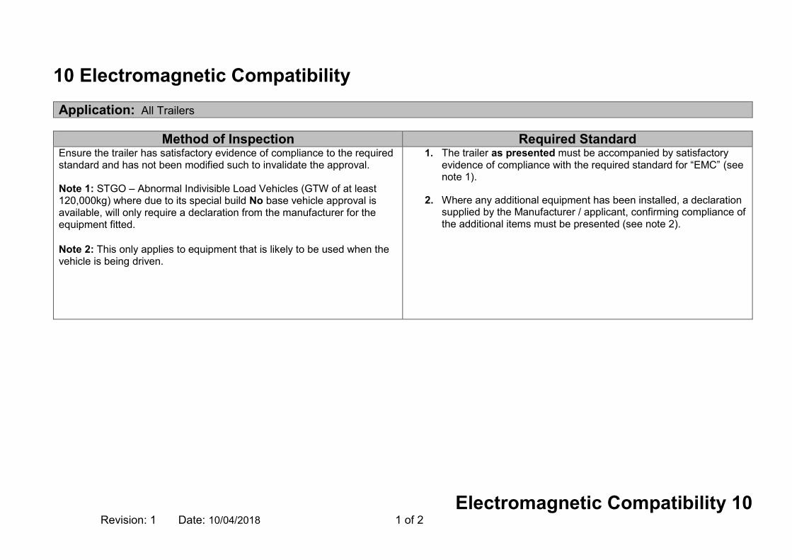
10 Electromagnetic Compatibility Application: All Trailers
Method of Inspection Required Standard
Ensure the trailer has satisfactory evidence of compliance to the required standard and has not been modified such to invalidate the approval. Note 1: STGO – Abnormal Indivisible Load Vehicles (GTW of at least 120,000kg) where due to its special build No base vehicle approval is available, will only require a declaration from the manufacturer for the equipment fitted. Note 2: This only applies to equipment that is likely to be used when the vehicle is being driven.
1. The trailer as presented must be accompanied by satisfactory evidence of compliance with the required standard for “EMC” (see note 1).
2. Where any additional equipment has been installed, a declaration
supplied by the Manufacturer / applicant, confirming compliance of the additional items must be presented (see note 2).

Electromagnetic Compatibility 10 Revision: 1 Date: 10/04/2018 2 of 2
Record of Revision
Revision Date Description of Change
1 10/04/2018 Added to trailer manual

Statutory Plates 18 Revision: 8 Date: 01/09/2018 1 of 8
18 Statutory Plates Application: All Trailers
Method of Inspection Required Standard
All vehicles must be provided with a manufacturer’s plate. Legislation places no restriction on the material from which the plate is made. The purpose of the plate is to impart information rather than to act as a proof of identity. Check that the manufacturer’s plate (in the case of a multistage build, one for each stage) complies with the Required Standards Separate plates should be fitted in close proximity to each other. Visually check that the characters used for the Manufacturers Plate and Trailer Identification Number (TIN) complies to the required standards. Where the vehicle is subject to a multistage build, a plate is required on completion of each stage as appropriate, every plate fitted must display the same VIN as displayed on the chassis, the weight information is only necessary on the chassis manufacturer’s plate or on a converters plate if they have altered those weights with any modification. The manufacturer may give additional information. The approval number and build stage number may be listed below the manufacturers name and the number of axles may be listed underneath the VIN number. Any other information must be outside a clearly marked rectangle which shall enclose only the listed information.
Manufacturers TIN Plate 1. The trailer must be fitted with a manufacturer’s plate in a conspicuous
and readily accessible position.
2. A manufacturer’s plate must be fitted for each stage of a multistage build.
3. The manufacturer’s plate(s) must be made of a durable material.
4. The manufacturer’s plate(s) must be indelibly marked with the Trailer Identification Number (TIN) which matches the number marked into the trailer structure. (See note1).
5. The manufacturer’s plate(s) must be securely attached to a part of the trailer that will not be replaced through normal use. (See note 2).
6. The manufacturer’s plate(s) must show the required information, in the correct order inside a clearly marked rectangle. See Annex 1
7. The Trailer Identification Number on the manufacturer’s plate must be marked in characters at least 4mm high.
8. The characters on the manufacturer’s plate (with the exception of the Trailer Identification Number) must be at least 2mm high.
Trailers exceeding the normal length or width (see Section 48B and 48C) (See Note 6)
9. The manufacturers plate must also show the following text “Designed to carry AIL of exceptional length.

Statutory Plates 18 Revision: 8 Date: 01/09/2018 2 of 8
Method of Inspection Required Standard The identification number of the base trailer (TIN) prescribed by Directive 76/114/EEC shall be retained during all the subsequent stages of the type-approval process to ensure the ‘traceability’ of the process. However, at the final stage of completion, the manufacturer concerned by this stage may replace, in agreement with the approval authority, the first and second sections of the trailer identification number with his own vehicle/trailer manufacturer code and the trailer identification code if, and only if, the trailer has to be registered under his own trade name. In such a case, the complete trailer identification number of the base vehicle must not be deleted.
All trailers must have a trailer identification number marked onto the chassis by hammering, stamping or similar so that the vehicle can be clearly identified. Note 1:- For markings to be considered 'indelible' they should be unlikely to become disfigured or obliterated during the life of the trailer. Whilst stamping or engraving is preferable it is possible to accept a printed or painted plate providing it has been treated in such a way that it is most unlikely that essential information would be obliterated or defaced during the normal life of the trailer. Note 2:- 'Securely attached' means screwed, bolted, riveted or otherwise fixed such that it is not likely to become displaced during the life of the trailer Note 3: As an exception, for technical reasons, it may also be marked on two lines. However, in this case no section may be divided between the two lines. The beginning and end of each line must be indicated by a symbol which is neither an Arabic numeral nor a roman capital letter, and which cannot be confused with
10. The manufacturers plate must also show the following text “Over-width trailer – for STGO use only”.
Permanent TIN Number
11. The TIN must be marked on the chassis, frame or other similar structure on the right hand side of the trailer. (viewed from the rear)
12. The TIN must be placed in a clearly visible and accessible position by a method such as hammering or stamping so that it cannot be obliterated or deteriorate.)
13. The TIN number must consist of 17 digits with the information shown in a single line (see notes 3 & 4).
14. Capital letters and numerals must be used for the TIN.
15. There must not be any gaps between the characters for the TIN or unique trailer identifier number shown on the manufacturer’s plate or stamped into the trailer. (See note 4).
16. The characters used for the TIN number stamped into the chassis, frame or other similar structure must be at least 7mm high.
17. Use of the letter I, the letter O, the letter Q, dashes, asterisks and other special signs are not permitted.
Where the TIN has been changed in agreement with the Approval Authority
18. Evidence of the agreement with the approval authority must be provided.
19. The original complete trailer identification number of the base trailer must be present on the chassis.
20. The complete new TIN must be stamped on the chassis as near as possible to the original TIN.

Statutory Plates 18 Revision: 8 Date: 01/09/2018 3 of 8
Method of Inspection Required Standard either. (First section would be 3 characters in length, second section would be 6 characters in length and the last section would be 8 characters in length). Note 4: The spacing of characters must be such that no additional characters could be added at a later date. Note 5: There is no specific format for the special type’s plate. The diagram shown is purely an example. It is important to ensure the presence of all relevant information.
Note 6: RS 9 & 10 are not applicable to modular trailers as defined in the foreword of this manual. The manufacturer may display this information on the plate at their discretion
The last eight characters of the new TIN must be identical to the last eight characters of the base trailer TIN 10/04/2018 Optional Dimension Plate O1 & O2 Trailers
21. Where fitted; a second plate must be fitted next to the manufacturer's plate and must contain the required dimensions listed in Annex 2
Special Types Plate See Note 5
22. Trailers intended for use under STGO cat 2 and 3 conditions must be fitted with a “Special Types” plate that is securely fixed to the trailer in a conspicuous and readily accessible position.
23. It must contain the heading “SPECIAL TYPES USE” in letters not less than 4mm high.
24. It must be indelibly marked, in letters and figures not less than 4mm high, with the maximum weights (in kg or tonnes) at which, in the opinion of the manufacturer, the trailer may be used legally in the UK when travelling on roads at or below the speed in question, as per the table below, (with the speeds and number of axles as applicable):
Axle 1 Axle 2 Axle 3 Axle 4 Max load on towing vehicle
Max gross weight
20 mph 25 mph 30 mph 35 mph 40 mph

Statutory Plates 18 Revision: 8 Date: 01/09/2018 4 of 8
Annex 1 Manufactures Plate (see note 1, 2, 3 & 4)
Name of Manufacturer Approval number and/or Build Stage number (If applicable) Trailer Identification Number (TIN) Maximum permitted laden mass of trailer Maximum permitted laden road mass for each axle, listed in order from front to rear
In the case of a Semi trailer, the maximum permitted mass on the fifth wheel kingpin (see note 5 & 6)
O1 trailers only, Year of manufacture (Optional for other categories) Note 1: Where the trailer is subject to a multistage build, a plate is required on completion of each stage as appropriate, every plate fitted must display the same TIN as displayed on the chassis, the weight information is only necessary on the chassis manufacturer’s plate or on a converters plate if they have altered those weights with any modification. Note 2: For markings to be considered 'indelible' they should be unlikely to become disfigured or obliterated during the life of the trailer. Whilst stamping or engraving is preferable it is possible to accept a printed or painted plate providing it has been treated in such a way that it is most unlikely that essential information would be obliterated or defaced during the normal life of the trailer.
Note 3: The spacing of characters must be such that no additional characters could be added at a later date. Note 4: If any of the technically permissible masses are higher than the masses permitted in GB and NI for a trailer or axle (see Annex 1 for details of the maximum masses permitted in GB and NI), then there should be 2 columns for masses - in the left hand column the maximum permitted mass in
DVSA MOTORS INC
e11*2007/46*0291*02
SA9A3ACTBE123456
38000Kg 41000Kg
8000Kg 9000Kg 8000Kg 9000Kg 8000Kg 9000Kg
14000Kg
2015

Statutory Plates 18 Revision: 8 Date: 01/09/2018 5 of 8
GB/NI, and in the right hand column, the technically permissible mass. This does not apply to a trailer issued with a Plating certificate under the Goods Vehicles (Plating and Testing) Regulations 1988 where only one column, giving the technically permissible masses, is permitted. (See Section 48) Note 5: It is acceptable if the maximum mass on the fifth wheel kingpin is listed above the mass of the first axle. Note 6: The maximum mass (T) on each axle group may be included within the rectangle.
Statutory Plates 18 Revision: 8 Date: 01/09/2018 6 of 8
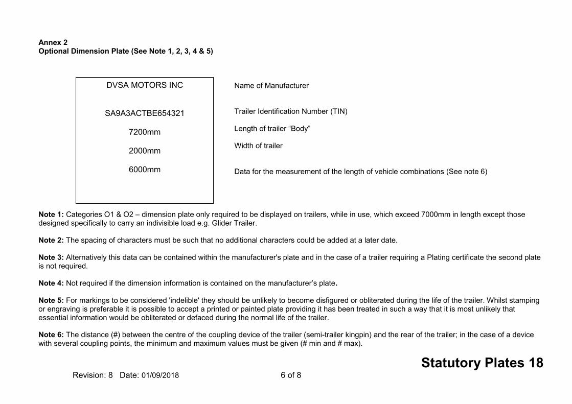
Annex 2 Optional Dimension Plate (See Note 1, 2, 3, 4 & 5)
Name of Manufacturer Trailer Identification Number (TIN) Length of trailer “Body” Width of trailer Data for the measurement of the length of vehicle combinations (See note 6) Note 1: Categories O1 & O2 – dimension plate only required to be displayed on trailers, while in use, which exceed 7000mm in length except those designed specifically to carry an indivisible load e.g. Glider Trailer. Note 2: The spacing of characters must be such that no additional characters could be added at a later date. Note 3: Alternatively this data can be contained within the manufacturer's plate and in the case of a trailer requiring a Plating certificate the second plate is not required. Note 4: Not required if the dimension information is contained on the manufacturer’s plate. Note 5: For markings to be considered 'indelible' they should be unlikely to become disfigured or obliterated during the life of the trailer. Whilst stamping or engraving is preferable it is possible to accept a printed or painted plate providing it has been treated in such a way that it is most unlikely that essential information would be obliterated or defaced during the normal life of the trailer. Note 6: The distance (#) between the centre of the coupling device of the trailer (semi-trailer kingpin) and the rear of the trailer; in the case of a device with several coupling points, the minimum and maximum values must be given (# min and # max).
DVSA MOTORS INC
SA9A3ACTBE654321
7200mm
2000mm
6000mm

Statutory Plates 18 Revision: 8 Date: 01/09/2018 7 of 8
Annex 3 Maximum permitted weights in Great Britain and Northern Ireland
Trailers Weight (GVW)
O1 Up to 750kg (0.75 tonnes)
O2 751kg (0.75 tonnes) up to 3500kg (3.5 tonnes)
O3 3501kg (3.5 tonnes) up to 10000kg (10.0 tonnes)
O4 10001kg (10.0 tonnes) +
Axles Weight
Single axle 10 tonnes
Tandem axles of trailers and semi-trailers
The sum of the axle weights must not exceed
Distance between axle centres is less than 1metre 11 tonnes
from 1metre and less than 1.3metres 16 tonnes
from 1.3metres and less than 1.8metres 18 tonnes
1.8metres or more 20 tonnes
Tri-axle trailers and semi-trailers
The sum of the axle weights must not exceed
from between axle centres 1.3metres or less 21 tonnes
from 1.3metres and up to 1.4metres 24 tonnes

Statutory Plates 18 Revision: 8 Date: 01/09/2018 8 of 8
Revision Date Description of Change
1 16/04/2009
2 28/02/2011 Reword MOI and add RS for Dimension plate
3 30/04/2012 Add information to MoI for VIN number sections and add new standards
4 29/10/2012 Amend RS6, insert new RS8, amend RS9 and renumber following RSs
5 29/10/2013 Amend RS6, 7 & 13, insert new notes 4, 9 & 10, link RS6 to notes 4, 5 & 9 and RS8 to notes 2, 3, 4 & 9
6 29/10/2014 Insert new RS7 and 8, Add new standards for STGO Plates RS23 – RS26, clarify RS 9 & note 10
7 10/04/2018 Section Rewrite
8 01/09/2018 Replace Max permitted weights in GB and NI table as Annex 3

Installation of Lights 20 Revision: 7 Date10/04/2018 1 of 8
20 Installation of Lights Application: All Trailers
Method of Inspection Required Standard
The examiner will perform a visual check of all lamps and reflectors fitted to the trailer to ensure the correct colour light is visible to the front or rear and that no light emitting surfaces are obscured. Lamp/reflector lateral position is measured from the extreme outer edge of the trailer (disregarding tyres, mirrors, lamps and reflectors) to the edge of the illuminated area (or reflective surface on a reflector) nearest that side of the trailer. Lamp/reflector vertical position is measured from the ground;
In the case of the minimum height to the lower edge of the illuminated area (reflective surface on a reflector).
In the case of the maximum height to the top edge of the
illuminated area (reflective surface on a reflector). Additional reflectors fitted to O3/O4 trailers do not have to be triangular in shape. Modular trailers as defined in the foreword of this manual, may be fitted with non permanently fixed lamp unit or units and conspicuity. These units must be fitted at time of examination, and have permanent locating devices to enable them to be fitted in one position only. All lamps will need to meet location requirements and angles of visibility. The positioning of the rear lamps will define the “Rear” of the trailer for the purpose of examination.
1. The trailer must be fitted with lamps or retro reflective material only capable of showing a white light to the front except for:
an amber light from a direction indicator An amber light from a hazard beacon/warning lamp a yellow light from a conspicuity marking material an amber light from a side marker light a green light from a ABS light emergency vehicles only, a blue light from an external warning
lamp or beacon
2. The trailer must be fitted with lamps or retro reflective material only capable of showing a red light to the rear except for:
an amber light from a direction indicator an amber light from a hazard beacon/warning lamp a white light from a work lamp, reversing lamp, interior lamp, or a
registration plate lamp a yellow light from a rear registration plate a yellow light from a conspicuity marking material an amber light from a side marker light emergency vehicles only, a blue light from an external warning
lamp or beacon. 3. The operation of any lamp must not affect any other lamp or be
affected by the operation of any other lamp, unless specifically designed to do so.

Installation of Lights 20 Revision: 7 Date10/04/2018 2 of 8
Method of Inspection Required Standard If workshop tools or equipment are required to reinstate the function of a lamp that 'lamp' should be considered not 'fitted'. If a stop lamp meets the criteria of an optional lamp and is 'fitted', i.e. connected it must operate. Two or more lamps (see “A” and “B” in Figure 4), whether identical or not, having the same function and emitting light of the same colour are considered to be one lamp if the aggregate illuminated area of the lamps occupies 60% or more of the area of the smallest rectangle circumscribing those illuminated areas. Note 1: This does not apply to rear retro reflectors which must be visible at all times.
4. All lamps, reflectors and rear markers must be securely fitted to the trailer and not move by swivelling, deflecting, or otherwise while the trailer is in motion, except for a work lamp, used to illuminate a working area or the scene of an accident, breakdown or road works in the vicinity of the trailer to which it is fitted.
5. All obligatory and optional lamps, reflectors and rear markers must be
fitted to their correct orientation.
6. When every door or other movable part is in the fixed open position (any position in which the component will remain, with or without a fixed stay) the
front and rear position lamps front and rear indicators rear retro reflectors
must fulfil one of the following conditions:
a. half (50%) of the apparent surface of the lamp or reflector is visible
from directly in front of / behind as appropriate the trailer, or
b. additional fully visible lamp (s) / reflectors satisfying all requirements for the above lamps / reflectors are activated / visible, or
c. a notice on the trailer must inform the user that in certain positions
of the movable components, other road users should be warned of the presence of the trailer on the road (e.g. by laying out a warning triangle). (See note 1).

Installation of Lights 20 Revision: 7 Date10/04/2018 3 of 8
Figure 1 Horizontal Angles of Visibility Each lamp and reflector must be positioned such as to provide an “apparent surface”. At least 50% of the “apparent surface” of each lamp or reflector must be visible from any point within the relevant angles.
30°
10°
Reflector
5°

Installation of Lights 20 Revision: 7 Date10/04/2018 4 of 8
Figure 2 Vertical Angles of Visibility Each lamp and reflector must be positioned such as to provide an “apparent surface”. At least 50% of the “apparent surface” of each lamp or reflector must be visible from any point within the relevant angles. Front Position Lamps, Retro Reflectors and Indicators (including Side Repeaters) ‘a’ = less than 750mm above ground level. ‘b’ = 750mm or more above ground level. ‘ar’ = Front retro reflector less than 750mm above ground level ‘br’ = Front retro reflector more than 750mm above ground level ‘c’ = Rear position lamps and Stop lamps 1500mm or more above ground level. Indicators and Rear reflectors 750mm or more above ground level. ‘d’ = Rear position lamps and Stop lamps less than 1500mm above ground level. ‘e’ = Rear position lamps, Stop lamps, Indicators and Rear reflectors less than 750mm above ground level. ‘f’ = Rear fog lamps.

Installation of Lights 20 Revision: 7 Date10/04/2018 5 of 8
Figure 3 “To the rear” of the trailer means “in an area the sides of which are at an angle of 15 degrees out from the extreme outer edge of the trailer, (starting from the rear corner) and extending up to 25m from the rear of the trailer (measured along the trailer longitudinal).

Installation of Lights 20 Revision: 7 Date10/04/2018 6 of 8
Figure 4

Installation of Lights 20 Revision: 7 Date10/04/2018 7 of 8
Record of Revision
Revision Date Description of Change
1 16/04/2009
2 28/02/2011 Add new RS 4 and renumber remaining standards
3 30/02/2012 Add exemptions to allowed light in RS 1 & 2
4 29/10/2012 Add angles of visibility of reflectors in Figures 1 & 2.
5 29/10/2013 Insert text in Note 2, correction to Figure 1, and amend Table 1 Side Retro-Reflectors (Application), insert new Fig. 4
6 29/10/2014 Add new Note 3
7 10/04/2018 Revise notes, rearrange RSs & add MOI Modular Trailers

Installation of Lights 20 Revision: 7 Date10/04/2018 8 of 8
This page intentionally left blank

Retro Reflectors 21 Revision: 7 Date: 10/04/2018 1 of 12
21 Retro Reflectors Application: (Reflectors) All Trailers, (Conspicuity Markings) O3 & O4 trailers more than 6 metres long and more than 2.1 metres wide. (Optional on O2 trailers; prohibited on O1 trailers.)
Method of Inspection Required Standard
Carry out a visual check of all mandatory retro reflectors, conspicuity marking and rear markers fitted to the trailer for colour, number, approval markings and correct positioning. Trailers are required to have a full contour marking on the rear, i.e. horizontal and vertical markings to outline the shape of the trailer, and partial contour markings on the side. Partial contour markings consist of a horizontal line showing the length of the trailer and ‘tick’ marks showing the upper corners of the trailer. (See figure 1, 2 & 3). Note 1: Geometric angles of visibility and positional requirements are not required for all optional reflectors and rear markers. Note 2: RS 1 is not applicable to O1 – O2 trailers imported from outside the EU. Note 3: Where the shape, structure, design or operational requirements make it impossible to install the mandatory contour marking, a line marking is acceptable (see figure 6).
Retro reflectors;
1. All reflectors must be ‘e’ or ‘E’ marked and where applicable, bear the appropriate identity marking as listed in Table 1 (see note 2).
2. The correct number must be fitted to the trailer (Table 1).
3. The correct colour must be fitted to the trailer (Table 1).
4. They must be positioned to meet (see note 1)
a. the positional requirements of Table 1
b. the angles of visibility requirements of Table 1
5. They must be of the correct shape (Table 1).
6. Rear reflectors must face predominately to the rear.
Conspicuity Markings; trailers above 3500kgs
7. Full or partial conspicuity markings must be fitted (see note 3). 8. Conspicuity Markings must only be applied to the correct category of trailer (see
application).
9. All conspicuity marking material must be of an approved type (see note 4).

Retro Reflectors 21 Revision: 7 Date: 10/04/2018 2 of 12
Method of Inspection Required Standard Note 4: Example of an Approval Mark
Symbol "C" indicates the class of the retro-reflective material which is intended for contour/strip marking.
Note 5: Markings are considered continuous if gaps are less than 50% of the length of adjacent elements, However, if the manufacturer can prove to the satisfaction of the authority responsible for type approval that it is impossible to respect the value of 50 per cent, the distance between adjacent elements may be larger than 50 per cent of the shortest adjacent element, and it shall be as small as possible and not exceed 1000 mm. Note 6: If 1500mm is not practicable this can be increased to 2500mm. Note 7: Rear marker plates (R70.01) count towards cumulative total width of conspicuity marking. Note 8: Overall trailer length excludes the drawbar. Note 9: Rear markers are not required to be fitted as long as the trailer has been fitted with Conspicuity Markings that comply to the required standards of this section. Note 10: Where it is impractical to meet the dimension stated in RS20, e.g. due to the position of load covers or similar equipment, full or partial upper markings (where fitted) should be located as close as is practical to the upper extremity.
10. There must be at least one visible approval mark on an element of a retro-reflective marking material fitted to each face of the vehicle (o/s, n/s & rear figure 7).
11. The maximum gap between adjacent elements must be no greater than 50% of
the smallest adjacent element (see note 5).
12. The lowest edge must be between 250mm and 1500mm from the ground. (See note 6).
13. The minimum width of the markings must be at least 50mm.
14. The maximum width of the markings must be no greater than 60mm.
Rear Conspicuity Markings; trailers over 3500kg and over 2.1m wide
15. must be coloured either red or yellow
16. must cover at least 70% of the overall trailer width (see note 7 & figure 5)
17. must be at least 200mm away from any mandatory brake light (see figure 4 A) Side Conspicuity markings; trailers over 3500kg and over 6 metres in length
18. must be coloured either white or yellow
19. must extend within 600mm of either end of the trailer (see figure 2)
20. must cover at least 70% of the overall trailer length (see note 8 & figure 5) If Full or Partial Contour Markings are fitted
21. The maximum height must be as close as is practical to the top of the body. (See figure 2 & Note 10).

Retro Reflectors 21 Revision: 7 Date: 10/04/2018 3 of 12
Method of Inspection Required Standard Note 11: The 250mm must be measurable on a flat plane. If the mark is fitted to a shaped surface (e.g. corrugations) the mark must be extended so that at least 250 mm is visible form the side.
22. The vertical aspect of marking must be as close to the edge as practicable. (See
figure 4 B).
23. Each side of a Tick Marking must be at least 250mm (see figure 3 & note 11). Rear Markers; (O1, O2 if over 8m in length and all O3 and O4)
24. All rear markers must bear the appropriate approval marks.
25. A minimum of one set of obligatory markers must be fitted to the trailer (see note 9 & Table 2).
26. They must be positioned correctly to meet the positional requirements of Table 2
(See note 1).
27. They must be of the correct type (Table 2).

Retro Reflectors 21 Revision: 7 Date: 10/04/2018 4 of 12
Table 1
TYPE NUMBER APPLICATION COLOUR
POSITION ANGLES OF VISIBILITY
(see figure 1 & 2 of section 20)
APPROVAL MARK “E” or “e” Identity Symbol or BS Mark /
Notes
MAX DISTANCE FROM SIDE
(mm)
MAX HEIGHT (mm)
MIN HEIGHT (mm)
Rear Retro Reflectors Triangular
(Optional reflectors may be any shape)
Min 2 Max any number Includes optional
Mandatory Red
400 (Min separation 600 unless trailer width
less than 1300, where
Min separation
400)
900 or if impracticable
1500
250
a. Horizontal i. 300 inwards and outwards. b. Vertical i. < 750mm above the ground 150 above and 50 below horizontal. ii. otherwise 150 above and below horizontal
IIIA or IIIB “E” or “e”
Front Retro Reflectors Non-triangular
Min 2 Max any number Includes optional
Mandatory White 150 900 or if
impracticable 1500
250
a. Horizontal i. 100 inwards and 300
outwards. b. Vertical i. < 750mm above the ground 150 above and 50 below horizontal. ii. otherwise 150 above and below horizontal
IA or IB “E” or “e”
Side Retro Reflectors Non-triangular See below
Mandatory on all trailers
Amber The
rearmost may be red if within 1m of the rear
N/A
1500 or if the shape of the
bodywork makes it
impossible 2100
250
a. Horizontal 45° to the front and to the rear b. Vertical i. < 750mm above the ground 150 above and 50 below horizontal. ii. otherwise 150 above and below horizontal
IA or IB “E” or “e”
At least one side reflector fitted to the middle third of the trailer The foremost side- reflector being not further than 3 m from the front The distance between two adjacent side- reflectors shall not exceed 3m (if bodywork makes it impracticable this distance may be increased to
4m) The distance between the rearmost side- reflector and the rear of the trailer shall not exceed 1 m

Retro Reflectors 21 Revision: 7 Date: 10/04/2018 5 of 12
Figure 4
Figure 1 Figure 2
Figure 3
The maximum height must be as close as is practical to the top of the body

Retro Reflectors 21 Revision: 7 Date: 10/04/2018 6 of 12
Rear marker plates are optional ( A, B, C ) Where fitted rear marker plates may only be counted as contributing to the rear contour marking (C) provided they comply with UNECE Regulation 70.01 Marker plates approved to UNECE Regulation 70.00 do not count towards the conspicuity marking

Retro Reflectors 21 Revision: 7 Date: 10/04/2018 7 of 12
Figure 5
Figure 6
Markings must cover at least 70% of the overall trailer width
Markings must cover at least 70% of the overall trailer length

Retro Reflectors 21 Revision: 7 Date: 10/04/2018 8 of 12
Table 2 Table 2
Typical examples of line markings

Retro Reflectors 21 Revision: 7 Date: 10/04/2018 9 of 12
1. Description A trailer if it forms part of a combination of vehicles the overall length of which does not exceed 11m:
A rear marking of a type shown in diagram 1, 2, 3 or 4 in Part III of this Section.
A trailer if it forms part of a combination of vehicles the overall length of which exceeds 11m but does not exceed 13m:
A rear marking of a type shown in Part III of this Section.
A trailer if it forms part of a combination of vehicles the overall length of which exceeds 13m:
A rear marking of a type shown in diagram 5, 6, 7 or 8 in Part III of this Section.
2. Position Longitudinal: At or near the rear of the trailer. A rear marking of a type shown in diagram 2, 3, 4, 6, 7 or 8 in Part III of this Section:
Each part shall be fitted as near as practicable to the outermost edge of the trailer so that no part of the marking projects beyond the outermost part of the trailer on either side.
A rear marking of a type shown in diagram 1 or 5 in Part III of this Section:
The marking shall be fitted so that the vertical centre-line of the marking lies on the vertical plane through the longitudinal axis of the trailer and no part of the marking projects beyond the outermost part of the trailer on either side.
Vertical: The lower edge of every rear marking shall be at a height of not more than 1700mm nor less than 400mm above the ground whether the trailer is laden or unladen.
3. Visibility: Plainly visible to the rear.
4. Alignment: The lower edge of every rear marking shall be fitted horizontally. Every part of a rear marking shall lie within 20° of a transverse vertical plane at right angles to the longitudinal axis of the trailer and shall face to the rear.
5. Markings
An approval mark to ECE Regulation 70 or 70:01. Example Marking
6. Colour: Red fluorescent material in the stippled areas shown in any of the diagrams in Part III of this Section and yellow retro reflective material in any of the areas so shown, being areas not stippled and not constituting a letter.
Part III

Retro Reflectors 21 Revision: 7 Date: 10/04/2018 10 of 12
Rear markings prescribed for Trailers (where required to be fitted)

Retro Reflectors 21 Revision: 7 Date: 10/04/2018 11 of 12
Record of Revision
Revision Date Description of Change
1 16/04/2009
2 28/02/2011 Add Conspicuity Markings and more acceptable markings for reflectors
3 30/04/2012 Re-order Rs for conspicuity markings, amend text for marker boards
4 29/10/2012 Reword statements on Figure 4 & remove labelling from tanker on page 7
5 29/10/2013 Revise Application header, insert new note 2 & RS6, link RS24 to note 7 and revise requirement for side Retro-Reflectors in table 1.
6 29/10/2014 Add new note 2 and renumber remaining notes
7 10/04/2018 Added note 10 & 11 Add RS6

Retro Reflectors 21 Revision: 7 Date: 10/04/2018 12 of 12
This page intentionally left blank

End-outline, Position (Side), Stop and Side Marker Lamps 22 Revision: 5 Date: 10/04/2018 1 of 6
22 End-outline, Position (Side), Stop and Side Marker Lamps Application: All Trailers
Method of Inspection Required Standard
Carry out a visual check of all outline marker, position, stop, side marker and daytime running lamps fitted to the trailer for operation, colour, number, approval marks and correct positioning. This includes all optional lamps. With optional lamps check that fitment is permitted and they do not exceed the maximum number of lamps of that type allowed to be fitted. In addition to the Required Standards, O3 & O4Trailers MAY have EITHER of (1) or (2) below: (1) Direction indicator side repeater lamps: Three category 5 side repeaters distributed as evenly as practicable along each side OR (2) Flashing Side marker lamps Mandatory amber side marker lamps may flash simultaneously with the direction-indicator lamps on the same side of the vehicle. Only one of the above specific combinations is allowed, no other combination is acceptable.
1. All lamps must be ‘e’ or ‘E’ marked and where applicable, bear the appropriate identity marking as listed in table 1 (See note 2).
Front and Rear Position Lamps;
2. The correct number must be fitted to the trailer (Table 1). 3. They must be operational.
4. They must only emit white light to the front / red light to the rear.
5. They must be positioned to meet (see note 1)
the positional requirements of Table 1
the angles of visibility requirements of Table 1
Stop Lamps;
6. The correct number must be fitted to the trailer (Table 1). 7. They must be operational.
8. They must only emit red light.
9. They must only illuminate when the service brake is applied, and must
extinguish when the service brake is released.

End-outline, Position (Side), Stop and Side Marker Lamps 22 Revision: 5 Date: 10/04/2018 2 of 6
Method of Inspection Required Standard Where (2) above is used, there is NO requirement for the side marker lamps to be marked in addition as side repeater lamps.
Note 1: Geometric angles of visibility and positional requirements are not required for all optional position lamps, stop lamps and end outline marker lamps. Note 2: RS 1 is not applicable to O1 – O2 trailers imported from outside the EU. Note 3: The inspection of the side marker lamps applies to the obligatory lamps fitted to all trailers exceeding 6m in length. Note 4: The inspection of end-outline marker lamps applies to the obligatory marker lamps fitted to trailers exceeding 2.10m in width.
Note 5: Both front and rear end outline marker lamps can be combined in one device.
Note 6: There is no requirement for special bracketry to be manufactured in order to accommodate these lamps.
10. They must be positioned to meet: (see note 1)
the positional requirements of Table 1
the angles of visibility requirements of Table 1 Side Marker lamps; ( see note 3 )
11. The correct number must be fitted to the trailer (in accordance to the positional requirements).
12. They must be operational.
13. They must emit an amber light (red is permitted if within 1 metre of the
rear).
14. They must be positioned to meet:
the positional requirements of Table 1 the angles of visibility requirements of Table 1
End Outline Marker Lamps; ( see note 4, 5 & 6 )
15. The correct number must be fitted to the trailer (Table 1). 16. They must be operational.
17. They must only emit red light to the rear / white light to the front.
18. The lights must be a minimum of 200mm from a positional lamp.
19. They must be positioned to meet: (see note 1)
the positional requirements of Table 1 the angles of visibility requirements of Table 1

End-outline, Position (Side), Stop and Side Marker Lamps 22 Revision: 5 Date: 10/04/2018 3 of 6
Table 1
TYPE NUMBER APPLICATION COLOUR
POSITION ANGLES OF VISIBILITY
(see figure 1 & 2 of section 20)
APPROVAL MARK “E” or “e” Identity
Symbol or BS Mark
MAX DISTANCE FROM SIDE
(mm)
MAX HEIGHT (mm)
MIN HEIGHT (mm)
Front Position Lamps
Min 2 Max any number Includes optional
lamps
Not required on trailers for the carriage and
launching of boats White 150
O1 / O2 2100
O3 / O4
1500 or if the structure
makes this impossible / impractical
2100
350
a. Horizontal i. 5° Inwards ii. 80° Outwards b. Vertical i. 15° Above and below the horizontal (May be reduced to 5° if the lamps are less than 750mm above the ground)
A “E” or “e” Mandatory on
trailers over 1600mm wide
Optional on other trailers
Rear Position Lamps Min 2
Max any number Includes optional
lamps
Mandatory Red 400
1500 or if the structure
makes this impossible / impractical
2100
350
a. Horizontal i. 45° Inwards 11. 80° Outwards b. Vertical i. 15° above and below the horizontal (May be reduced to 5° if the lamps are less than 750mm above the ground)
R “E” or “e”
Stop Lamps Min 2
Max any number Includes optional
lamps
Mandatory Red
One on each side of
longitudinal axis (Min
separation 600mm.
400mm if the overall width of vehicle is
less than 1,300mm.
1500 or if the structure
makes this impossible /
impracticable 2100
350
a. Horizontal i. 450 inwards and outwards b. Vertical i. as rear position lamps.
S1 or S2 “E” or “e”
Stop Lamps (Optional)
Min 1 Max any number
Optional Red
If 1 is fitted: as close to trailer centre-line as
practicable If 2 are fitted:
n/a
no lower than the
mandatory stop lamps
Must face the rear S1 or S2 “E” or “e”

End-outline, Position (Side), Stop and Side Marker Lamps 22 Revision: 5 Date: 10/04/2018 4 of 6
TYPE NUMBER APPLICATION COLOUR
POSITION ANGLES OF VISIBILITY
(see figure 1 & 2 of section 20)
APPROVAL MARK “E” or “e” Identity
Symbol or BS Mark
MAX DISTANCE FROM SIDE
(mm)
MAX HEIGHT (mm)
MIN HEIGHT (mm)
no requirement
End Outline Marker Lamp
2 visible from the front and 2 visible
from the rear Max any number Includes optional
lamps
Mandatory on all trailers exceeding
2.10m wide
Front- White
Rear - Red
As close as possible to the extreme edge and not more than 400mm
from the edge
Front and Rear: as high as possible, where trailer
structure exists to
mount the lamps on
(See note 5)
a. Horizontal i. 80° Outwards b. Vertical i. 5° Above the horizontal ii. 20° Below the horizontal
A or R “E” or “e”
Side Marker Lamp See below
All trailers where the length
exceeds 6m (The length of
trailers includes the drawbars)
Not required on trailers for the carriage and
launching of boats
Amber
The rearmost marker
may be red
N/A
1500 or if impracticable
2100
250
a. Horizontal i. 45° to the front and rear (Can be reduced to 30° if fitted as an optional extra) b. Vertical i. 10° Above and below the horizontal (The vertical angle below the horizontal may be reduced to 5° if the side marker lamp is fitted less than 750mm from the ground)
SM(1) “E” or “e”
Side Marker Lamp Spacing
at least one side-marker lamp must be fitted to the middle third of the trailer the foremost side-marker lamp being not further than 3 m from the front the distance between two adjacent side-marker lamps shall not exceed 3 m, if bodywork makes it impracticable this distance may be
increased to 4 m the distance between the rearmost side-marker lamp and the rear of the trailer shall not exceed 1 m
End-outline, Position (Side), Stop and Side Marker Lamps 22 Revision: 5 Date: 10/04/2018 5 of 6
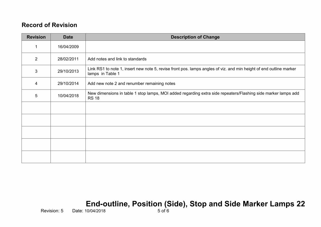
Record of Revision
Revision Date Description of Change
1 16/04/2009
2 28/02/2011 Add notes and link to standards
3 29/10/2013 Link RS1 to note 1, insert new note 5, revise front pos. lamps angles of viz. and min height of end outline marker lamps in Table 1
4 29/10/2014 Add new note 2 and renumber remaining notes
5 10/04/2018 New dimensions in table 1 stop lamps, MOI added regarding extra side repeaters/Flashing side marker lamps add RS 18

End-outline, Position (Side), Stop and Side Marker Lamps 22 Revision: 5 Date: 10/04/2018 6 of 6
This page intentionally left blank

Direction Indicators 23 Revision: 4 Date: 10/04/2018 1 of 4
23 Direction Indicators Application: All Trailers
Method of Inspection Required Standard
Carry out a visual check of all direction indicators fitted to the trailer for operation, colour, number, approval marks and correct positioning. With optional lamps check that fitment is permitted and they do not exceed the maximum number of lamps allowed to be fitted. The inspection of hazard warning lamps applies to all the obligatory direction indicator and side repeater lamps fitted to the trailer. In addition to the Required Standards, O3 & O4Trailers MAY have EITHER of (1) or (2) below: (1) Direction indicator side repeater lamps: Three category 5 side repeaters distributed as evenly as practicable along each side OR (2) Flashing Side marker lamps Mandatory amber side marker lamps may flash simultaneously with the direction-indicator lamps on the same side of the vehicle. Only one of the above specific combinations is allowed, no other combination is acceptable Where (2) above is used, there is NO requirement for the side marker lamps to be marked in addition as side repeater lamps.
Directional Indicators; 1. All lamps must be ‘e’ or ‘E’ marked and where applicable, bear the
appropriate identity marking as listed in table 1 (see note 2).
2. They must be operational.
3. The correct number must be fitted to the trailer (Table 1).
4. They must flash at a rate of between 60 and 120 times a minute (with all mandatory indicators working, and with the engine running on the towing vehicle if initially below the requirement).
5. All lamps must emit amber light.
6. They must be positioned to meet (see note 1)
a. the positional requirements of Table 1
b. the angles of visibility requirements of Table 1
Hazard Warning Lights;
7. The hazard warning device must operate all of the direction indicators simultaneously.

Direction Indicators 23 Revision: 4 Date: 10/04/2018 2 of 4
Method of Inspection Required Standard Note 1: Geometric angles of visibility and positional requirements are not required for all optional direction indicator lamps. Note 2: RS 1 is not applicable to O1 – O2 trailers imported from outside the EU.

Direction Indicators 23 Revision: 4 Date: 10/04/2018 3 of 4
Table 1
TYPE NUMBER APPLICATION COLOUR
POSITION ANGLES OF VISIBILITY
(see figure 1 & 2 of section 20)
APPROVAL MARK “E” or “e” Identity
Symbol or BS Mark / Notes
MAX DISTANCE FROM SIDE
(mm)
MAX HEIGHT (mm)
MIN HEIGHT (mm)
Direction Indicators
& Hazard Warning
Trailers On each side
Rear – One
O2,3 & 4 only -plus 2 optional
all vehicles- Rear only
Optional
Up to 3 (category 5) or
1 (Category 6) if vehicle over 9m
in length
Mandatory Amber
400 (min separation 600 unless
trailer width is less than
1300 where min
separation is 400)
1500 or if impracticable
2100
350
a. Horizontal i. 800 outwards 450 inwards. b. Vertical i. < 750mm above the ground 150 above and 50 below horizontal. ii. Otherwise 150 above and below horizontal.
Rear
2a, 2b or 12
“E” or “e”

Direction Indicators 23 Revision: 4 Date: 10/04/2018 4 of 4
Record of Revision
Revision Date Description of Change
1 16/04/2009
2 28/02/2011 Add text to MOI, link note to standards and amend maximum height figure
3 29/10/2014 Add new note 2
4 10/04/2018 MOI added regarding extra side repeaters/Flashing side marker lamps

Rear Registration Lamps 24 Revision: 3 Date: 29/10/2014 1 of 2
24 Rear Registration Lamps Application: All Trailers
Method of Inspection Required Standard
Carry out a visual check of all rear registration plate lamps fitted to the trailer for operation, colour and correct positioning. Note 1: RS 1 is not applicable to O1 – O2 trailers imported from outside the EU. Note 2: See section 4 Rear Registration Plate Space in conjunction with position of rear registration plate lamp.
Rear registration plate lamps;
1. All lamps must be ‘e’ or ‘E’ marked (see note 1).
2. They must be operational.
3. They must be able to be switched on and off with the front and rear position lights by operating one switch.
4. They must only emit white light.
5. They must be positioned sufficient to illuminate the rear registration
plate.

Rear Registration Lamps 24 Revision: 3 Date: 29/10/2014 2 of 2
Record of Revision
Revision Date Description of Change
1 16/04/2009
2 28/02/2011 Remove the reference to optional lamps
3 29/10/2014 Add new note 1 and renumber remaining notes
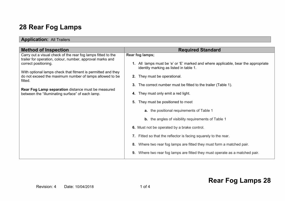
Rear Fog Lamps 28 Revision: 4 Date: 10/04/2018 1 of 4
28 Rear Fog Lamps Application: All Trailers
Method of Inspection Required Standard Carry out a visual check of the rear fog lamps fitted to the trailer for operation, colour, number, approval marks and correct positioning. With optional lamps check that fitment is permitted and they do not exceed the maximum number of lamps allowed to be fitted. Rear Fog Lamp separation distance must be measured between the “illuminating surface” of each lamp.
Rear fog lamps;
1. All lamps must be ‘e’ or ‘E’ marked and where applicable, bear the appropriate identity marking as listed in table 1.
2. They must be operational.
3. The correct number must be fitted to the trailer (Table 1).
4. They must only emit a red light.
5. They must be positioned to meet
a. the positional requirements of Table 1
b. the angles of visibility requirements of Table 1
6. Must not be operated by a brake control.
7. Fitted so that the reflector is facing squarely to the rear.
8. Where two rear fog lamps are fitted they must form a matched pair.
9. Where two rear fog lamps are fitted they must operate as a matched pair.

Rear Fog Lamps 28 Revision: 4 Date: 10/04/2018 2 of 4
Table 1
TYPE NUMBER APPLICATION COLOUR
POSITION ANGLES OF VISIBILITY
(see figure 1 & 2 of section 20)
APPROVAL MARK “E” or “e” Identity
Symbol or BS Mark / Notes
MAX DISTANCE FROM SIDE
(mm)
MAX HEIGHT
(mm) MIN HEIGHT
(mm)
Rear Fog Lamp Min 1 Max 2
All Trailers of 1300mm in width
or greater Red
At least one must be on
centre line or to offside of trailer (Min separation
distance from stop lamp 100)
see note 1
1000
or for rear fog lamps grouped with any
rear lamp, the
maximum height may
be increased
to 1,200mm.
250
a. Horizontal i. 250 inwards and outwards; if two lamps are fitted it is sufficient if one lamp (not necessarily the same lamp) – is visible throughout the range b. Vertical i. 50 above and below horizontal.
B or F “E” or “e”

Rear Fog Lamps 28 Revision: 4 Date: 10/04/2018 3 of 4
Record of Revision
Revision Date Description of Change
1 16/04/2009
2 28/02/2011 Remove the word “Optional” from application bar
3 29/10/2013 Amend RS8 & 9
4 10/04/2018 Amend maximum height requirements Table 1

Rear Fog Lamps 28 Revision: 4 Date: 10/04/2018 4 of 4
This page intentionally left blank
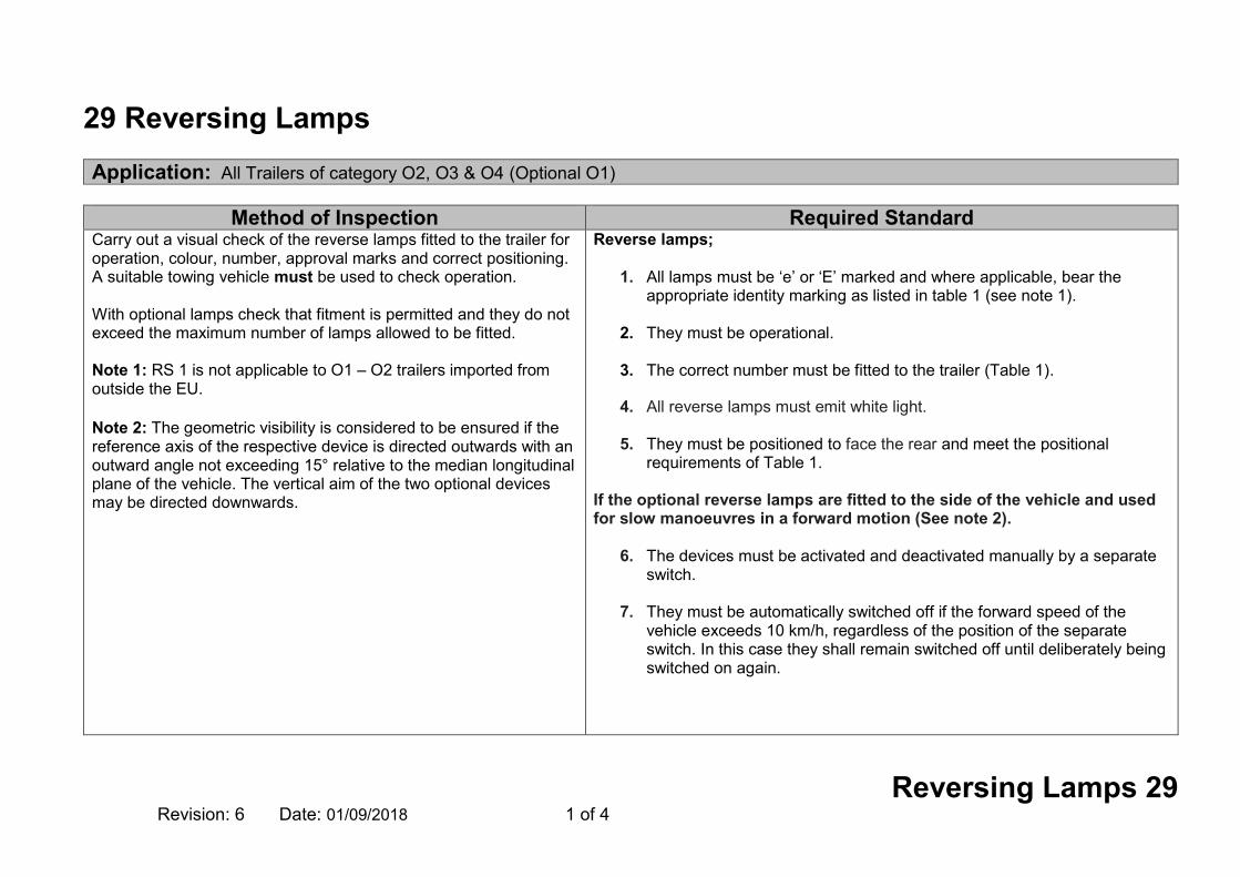
Reversing Lamps 29 Revision: 6 Date: 01/09/2018 1 of 4
29 Reversing Lamps Application: All Trailers of category O2, O3 & O4 (Optional O1)
Method of Inspection Required Standard
Carry out a visual check of the reverse lamps fitted to the trailer for operation, colour, number, approval marks and correct positioning. A suitable towing vehicle must be used to check operation. With optional lamps check that fitment is permitted and they do not exceed the maximum number of lamps allowed to be fitted. Note 1: RS 1 is not applicable to O1 – O2 trailers imported from outside the EU. Note 2: The geometric visibility is considered to be ensured if the reference axis of the respective device is directed outwards with an outward angle not exceeding 15° relative to the median longitudinal plane of the vehicle. The vertical aim of the two optional devices may be directed downwards.
Reverse lamps;
1. All lamps must be ‘e’ or ‘E’ marked and where applicable, bear the appropriate identity marking as listed in table 1 (see note 1).
2. They must be operational.
3. The correct number must be fitted to the trailer (Table 1).
4. All reverse lamps must emit white light.
5. They must be positioned to face the rear and meet the positional
requirements of Table 1. If the optional reverse lamps are fitted to the side of the vehicle and used for slow manoeuvres in a forward motion (See note 2).
6. The devices must be activated and deactivated manually by a separate switch.
7. They must be automatically switched off if the forward speed of the
vehicle exceeds 10 km/h, regardless of the position of the separate switch. In this case they shall remain switched off until deliberately being switched on again.

Reversing Lamps 29 Revision: 6 Date: 01/09/2018 2 of 4
Table 1
TYPE NUMBER APPLICATION COLOUR
POSITION
ANGLES OF VISIBILITY
APPROVAL MARK “E” or “e” Identity
Symbol or BS Mark / Notes
MAX DISTANCE FROM SIDE
(mm)
MAX HEIGHT (mm)
MIN HEIGHT (mm)
Reversing Lamps
Min 1 Max 2
Optional on O1 Mandatory O2 – O4 Trailers up to 6000mm
White
1200 250
Figure 3 Section 20
A or R “E” or “e”
Min 2 mandatory Max 2 optional
Trailers with a length exceeding 6000mm
If optional lamps are fitted to the side of the vehicle
Outwards
Maximum 15° relative to the median longitudinal plane
See Note 2

Reversing Lamps 29 Revision: 6 Date: 01/09/2018 3 of 4
Record of Revision
Revision Date Description of Change
1 16/04/2009
2 28/02/2011 Reword RS 5
3 29/10/2013 Revise table 1 Max & Min number of lamps
4 29/10/2014 Add New Note 1
5 10/04/2018 Add MOI & Note 2 revise table 1
6 01/09/2018 MOI expanded to require suitable towing vehicle.
Reversing Lamps 29 Revision: 6 Date: 01/09/2018 4 of 4
This page intentionally left blank

Heating Systems 36 Revision: 3 Date: 10/04/2018 1 of 4
36 Heating Systems Application: All Trailers (if fitted)
Method of Inspection Required Standard
Ensure that the trailer presented has satisfactory evidence of compliance to the required standard. Heating Systems must be fitted as to present no danger to passengers or other persons. Note 1 A combustion heater requires documentary evidence or an ‘E’ marked component plus an Installation Check. Note 2 A permanent notice stating that the heating system must not be used and the gas cylinder valve must be closed when the vehicle is in motion or words to that effect.
Combustion Heater
1. The trailer must be accompanied by satisfactory evidence of compliance with the required standard for “Heating Systems” .See note 1.
Combustion heater Installation Check
2. It must be positioned so that it is not likely to cause injury.
3. Heater utilising a liquid or gaseous fuel must be fitted to the manufacturer’s instructions.
4. There must be no obvious fire risk associated with the heating
system (e.g. flammable parts of the vehicle near to a source of heat or a likelihood of users placing objects liable to catch fire on a very hot surface).
5. It must be positioned so that it is not likely to cause injury.
6. It must be positioned so exhaust gases are not likely to enter
the accommodation / exhibition compartment.

Heating Systems 36 Revision: 3 Date: 10/04/2018 2 of 4
Method of Inspection Required Standard LPG heating systems for stationary use only. (See note 2)
7. Permanent warning labels/pictograms must be attached :
o on the compartment where portable LPG cylinders are stored
and
o in close proximity to the control device for the heating system,

Heating Systems 36 Revision: 3 Date: 10/04/2018 3 of 4
Record of Revision
Revision Date Description of Change
1 16/04/2009
2 29/10/2013 Insert new note 1 & RS7
3 10/04/2018 Reword Note, renumber RSs

Heating Systems 36 Revision: 3 Date: 10/04/2018 4 of 4
This page intentionally left blank

Lateral Protection System (Side Guards) 42 Revision: 6 Date: 10/04/2018 1 of 10
42 Lateral Protection System (Side Guards) Application: All Trailers of category O3 and O4
Method of Inspection Required Standard
A trailer of category O3 or O4 is not required to be fitted with a separate lateral protection device, providing the sides of the trailer are so designed and/or equipped that by their shape and characteristics their component parts together meet the requirements in standards 2 to 18. On a trailer fitted with extendible legs to provide additional stability during loading, unloading or other operations for which the trailer is designed, the side guard may be arranged with additional gaps where these are necessary to permit extension of the legs. On a trailer equipped with anchorage points for ro-ro transport, gaps shall be permitted within the side guard to accept the passage and tensioning of fixing lashings. An extendable trailer must comply with all the relevant requirements, when in its closed (non extended) position. Exempt Trailers (including STGO): Semi-trailer where the distance from the king pin to the foremost axle centre is less than 4.5m. Vehicle transporters (trailers designed to carry other vehicles loaded onto it from the rear) exempt where the chassis rails are on the extremities of the vehicle.
1. Where the side of the body does not meet the requirements, a side guard device must be fitted.
Requirements for both body sides and separate devices: Required area to be protected
2. The device or body side must have its rearward edge extended to within 300mm of the tyre on the first rear axle. (see note 1 & figure 1)
3. On a draw bar trailer the front edge of the guard must be no more than
500mm to the rear of the rearmost part of the tyre on the wheel immediately forward of the guard. (See note 1)
4. On a centre axle trailer the front edge of the guard must extend no further
than the front of the bodywork, (if any), or the chassis where the drawbar connects and must not affect normal manoeuvrability of the trailer.
5. On a semi-trailer the front edge of the guard must be no more than 250mm
to the rear of the centre line of the support legs, but in any case never more than 2.7m behind the centre of the king pin. (see figure 1)
6. The device or body side must be within 350 mm of the body line (see note
2). 7. The device or body side lower edge must be no higher than 550 mm from
the ground.

Lateral Protection System (Side Guards) 42 Revision: 6 Date: 10/04/2018 2 of 10
Method of Inspection Required Standard Low Loader if the upper surface of load platform <750mm above the ground. Gulley emptiers, where fitting of a lateral protection device prevents the use of the suction tube (not merely hinders). Trailers specially designed and constructed for the carriage of very long loads of indivisible length, such as timber, steel bars, etc. Trailers specifically designed and constructed for a purpose where the fitment of a lateral protection device would prevent the use of that equipment fitted (not merely hinders). A tank-trailer designed solely for the carriage of fluid substance in a closed tank permanently fitted to the vehicle and provided with hose or pipe connections for loading or unloading, shall be fitted with side guards which comply so far as is practicable with all the requirements of this section; strict compliance may be waived only where operational requirements make this necessary. Road Recovery Trailer (O4 trailer used under STGO). Modular trailers as defined in the foreword of this manual. Note 1: The measurement is taken to a vertical plane extending from the surface of the tread closest to the guard or relevant body work. Note 2: The ‘Body Line’ is that part of the structure of the trailer, cut or contacted by a vertical plane tangential to the outer surface of the tyres, except in the following cases: Where the plane does not cut the structure of the trailer, the upper edge shall be level with the surface of the load-carrying platform,
Within the defined area the following standards must be met 8. The device or body sides must be constructed of a suitable material and
must be of sufficient strength as to offer effective protection to unprotected road users (see note 3).
9. The device or body side must have a smooth or horizontally corrugated surface (see note 4).
10. Any external edges and corners must be rounded with a radius of at least
2.5mm. 11. There must be no projecting brackets , bolt heads or similar protrusions
(see notes 5 and 6). 12. The device or body side must be continuous in length (see note 7). 13. The device or body side must not have the rearward end more than
30mm inboard from the outermost edge of the rear tyres over at least the last 250mm of the device / body.
Where equipment is incorporated into the side guard,
14. The equipment must have a smooth substantially flat or horizontally corrugated outer surface. (See note 4).
15. There must not be a gap of more than 25 mm between it and the guard or
body side (see note 7 and 8, figure 2 & 4). 16. Where necessary the equipment must meet any required dimensional
requirement as if it was part of the device. 17. There must be no projecting brackets or hinges unless suitably radiused
from all aspects (see note 5 and 6).

Lateral Protection System (Side Guards) 42 Revision: 6 Date: 10/04/2018 3 of 10
Method of Inspection Required Standard or
950mm from the ground, whichever is the less. Where the plane cuts the structure of the trailer at a level more than 1.3m above the ground, then the upper edge of the side guard shall not be less than 950mm above the ground. Note 3: "Unprotected road users" means pedestrians, cyclists or motor cyclists using the road in such a way that they are liable to fall under the sides of the vehicle and be caught under the wheels. Note 4: Any adjacent parts may overlap providing that all overlapping edges face rearwards or downwards. Note 5: Dome shaped bolt heads and rivets, or other parts provided they are similarly rounded and smooth protruding to a maximum of 10mm in height are acceptable. Note 6: Where items protruding less than 5mm are added to the outer surface of Lateral Protection Devices, the edges only require blunting; corners will however require a radius of at least 2.5mm in two planes. Note 7: Combinations of surfaces and rails shall be considered as a continuous side guard as long as the gaps between them are no greater than 25mm. Note 8: A gap of 130mm either side of a crane / stabiliser leg is permitted (see figure 4). Note 9: “Open Space”, is defined as a gap of more than 25mm. Note 10: The inward measurement is taken at 90 degrees to the longitudinal plane of the trailer from the outer face of the guard; the
18. It must not have protruding bolt heads or similar protrusions (see note 5 and 6).
19. Any external edges and corners must be rounded with a radius of at least
2.5mm.
Additional requirements for separate devices
20. The device must be attached securely.
21. The device must consist of at least one horizontal rail (see note 2).
22. Where more than one horizontal rail is used, the rails must be not more than 300mm apart.
23. O3 trailers the horizontal rails must have a section height of at least 50 mm (figure 3A).
24. O4 trailers the horizontal rails must have a section height of at least 100 mm (figure 3B).
25. It must have a forward facing edge of at least 100 mm.
26. The side guard must be no more than 150mm inboard from the outermost plane of the trailer.
27. It must not increase the overall width of the trailer.

Lateral Protection System (Side Guards) 42 Revision: 6 Date: 10/04/2018 4 of 10
Method of Inspection Required Standard actual face of the portion turned inwards may be between 90 and 45 degrees from the same plane towards the front of the trailer.
28. The device must not be used for the attachment of air or hydraulic brake pipes.
29. Where the forward edge lies in open space (see note 9) then the following requirements must be met:-
a. There must be a continuous vertical member extending over the whole height of the device.
b. For O3 trailers, the outer and forward faces must measure at least 50 mm rearward and be turned 100 mm inwards. (See note 10 and figure 3)
c. For O4 trailer, the outer and forward faces must measure at least 100 mm rearward and be turned 100 mm inwards. (See note 10 and figure 3)

Lateral Protection System (Side Guards) 42 Revision: 6 Date: 10/04/2018 5 of 10
Figure 1
The front edge of the guard must be no more than 250mm to the rear of the centre line of the support legs
The rearward edge must extended to within 300mm of the tyre on the first rear axle
Maximum Inset is 30mm inboard from the outermost edge of the rear tyres

Lateral Protection System (Side Guards) 42 Revision: 6 Date: 10/04/2018 6 of 10
Figure 2
Gaps 25mm maximum where equipment is incorporated into the side guard

Lateral Protection System (Side Guards) 42 Revision: 6 Date: 10/04/2018 7 of 10
Figure 3A Figure 3B

Lateral Protection System (Side Guards) 42 Revision: 6 Date: 10/04/2018 8 of 10
Figure 4
Maximum permitted gap 130mm
Stabiliser Leg

Lateral Protection System (Side Guards) 42 Revision: 6 Date: 10/04/2018 9 of 10
Record of Revision
Revision Date Description of Change
1 16/04/2009
2 28/02/2011 Add exemptions, add text to required standards and add figure 4
3 30/04/2012 Amend exemptions
4 29/10/2013 Amend RS1 & 2, insert new RS4
5 29/10/2014 Add STGO Exemption
6 10/04/2018 Modular trailers added to exemptions RS 7, 9 & 11 revised, Note 9 added, figure 1,& 3 revised & RS23 & 24 reversed .

Lateral Protection System (Side Guards) 42 Revision: 6 Date: 10/04/2018 10 of 10
This page intentionally left blank

Spray Suppression 43 Revision: 5 Date: 10/04/2018 1 of 12
43 Spray Suppression Application: All Trailers of category O3 and O4
Method of Inspection Required Standard
All road wheels must be fitted with Spray Suppression devices. Exempt Trailers :
Vehicle Type Exemption Provided Trailers with tipper bodies – side tipping or rear tipping
Tippers with open-backed bodies are exempt from spray suppression, but require mud guards.
Trailers designed to carry timber, beams or girders of exceptional length
Trailers specially designed and constructed for the carriage of very long loads of indivisible length, such as timber, steel bars, etc. are exempt from spray suppression but require mudguards.
Refuse trailers (including skip),
Exemption from spray suppression, but will require mud guards.
STGO Modular Trailers Exemption from BOTH spray suppression and mudguards.
Mudguards must comply with RS 4, 5, 6 & 7 STGO Exempt Vehicles: Abnormal Indivisible Load (AIL) Trailers > 2.55m and/or > 12m long which are either Cat 2 <80T or Cat 3 <150T or >150T
Component Check
1. Every road wheel must be fitted with a Spray Suppression system. 2. All Spray Suppression material must be of an approved type. (See
note 1 and 2) 3. All components must be secured so that they perform their function.
Installation Check Mudguards (fitted in combination with energy absorption materials).
4. must fully cover the zone immediately above, ahead and behind any part of the tyre or tyres.
5. in the case of non steered wheels must have the lower front edge no
more than 45 degrees above the horizontal line of the axle (A on figure 1).
6. in the case of steered wheels must have the lower front edge no
more than 45 degrees above the horizontal line of the axle (A on figure 1).
7. must have the lower rear edge no more than 100mm above the
horizontal line of the axle (C on figure 1).

Spray Suppression 43 Revision: 5 Date: 10/04/2018 2 of 12
Method of Inspection Required Standard Definitions Mudguard Is a device to prevent as far as practical mud or water being thrown from a tyre. They may be formed using parts of the body or they may be an entirely separate unit. Outer Valances Are usually strips of material that are fitted longitudinally across a wheel space attached at one end to a rain flap to form an outer wheel arch lip, a vertical downward face that closes off what would be an open area. Rain flaps Can be a flexible extension to a mudguard or it may form the rear most vertical face of a mudguard in conjunction with the body, in this latter case it must be treated as a mudguard and be securely fixed to prevent excessive movement. Lifting axles Where a trailer is fitted with one or more lifting axles, the spray-suppression system must cover all the wheels when the axle is lowered and the remaining wheels which are in contact with the ground when the axle is raised. Self-tracking axles Where a trailer is fitted with a self-tracking axle, the spray-suppression system must satisfy the conditions applicable to non-steered wheels if mounted on the pivoting part. If not mounted on that part, it must satisfy the conditions that are applicable to steered wheels. Note 1: All spray suppression materials must be either e marked or be accompanied by an e marked sample of the material to permit the examiner to make a comparison.
8. must have Spray Suppression material fitted to the front face of the rear of the guard facing the tyre tread, complying with the dimensional requirements of figure 1. and 3.
9. that consist of several components must have no gaps between or
within individual parts when assembled that will permit the exit of spray when the trailer is in motion.
Additional standard where Separate Mudguards are fitted (in combination with air/water separation to multiple axle configurations).
10. where the distance between the tyres on adjacent axles does not exceed 300 mm the mudguards must also conform to the model shown in Figure 7.
Alternative Standards from standards 4-10 where the body forms the mudguards (and energy absorption systems are fitted).
11. must cover the zone above the tyre or tyres from the front edge of the tyre to the rain flap located behind the wheel see figure 5.
12. must have their inner faces made from or be fitted with a spray
suppression material. Outer Valances (with energy absorption Spray Suppression systems installed).
13. fitted to steered and self-steered wheels must have its vertical face within 100mm of the tyre wall (D on figure 2) see note 3.
14. fitted to non -steered wheels must have its vertical face within 75
mm of the tyre wall (D on figure 2) see note 3.
15. must have a depth of at least 45mm, at all points behind a vertical line passing through the centre of the wheel see Figure 2.

Spray Suppression 43 Revision: 5 Date: 10/04/2018 3 of 12
Method of Inspection Required Standard Note 2: ‘Spray-suppression device’ means part of the spray-suppression system, which may comprise: Air/water separator: This is a component forming part of the valance and/or of the rain flap through which air can pass whilst reducing pulverized water emissions. Or Energy absorber: This is a component forming part of the mudguard and/or valance and/ or rain flap which absorbs the energy of water spray, thus reducing pulverized water spray. Note 3: Where rope hooks are fitted the outer valance may meet the requirements of figure 6 as an alternative. Note 4: The maximum height of the bottom edge of the rain flap in relation to the ground, may be raised to 300 mm if the manufacturer deems it technically appropriate with regard to the suspension characteristics e.g. ‘road friendly’ suspension.
16. fitted to steered wheels must have the lower edge within1.8 x tyre
radius at points A,B and C as shown in Figure 4.
17. fitted to non - steered wheels must have the lower edge within1.5 x tyre radius at points A,B and C as in Figure 4.
18. must have no openings in them or between them and other parts of
the mudguard enabling spray to emerge. Alternative standards (to 13 -18 ) for Outer Valances (where the body forms the mudguard over non steered or self steering wheels and an energy absorption spray suppression system is installed).
19. must be located above each wheel of multiple axles where a rain flap is fitted between each wheel. See figure 5.
. 20. must have the entire inner surface fitted with an energy-absorption
spray-suppression material. 21. must be a minimum of 100mm high.
22. must have no openings in them or between the outer valance and
the inner part of the mud guard enabling spray to emerge. .
23. must be continuous where rain flaps are not fitted behind each wheel, they must extend between the outer edge of the rain flap and a vertical plane passing through the front edge of the tyre. See figure 5.
Outer Valances (with air/water separation Spray Suppression systems installed).
24. must have air/water separator spray-suppression devices fitted to the lower edges.

Spray Suppression 43 Revision: 5 Date: 10/04/2018 4 of 12
Method of Inspection Required Standard
25. must have a depth of at least 45mm, at all points behind a vertical
line passing through the centre of the wheel
26. fitted to steered wheels must have its lowest edge within 1.05 x tyre radius see figure 7
27. fitted to non-steered wheels must have its lowest edge within 1 x
tyre radius see figure 7
28. must have no openings in them or between them and the mudguard enabling spray to emerge
29. in the case of non steered wheels must have the lower front edge no
more than 20 degrees above the horizontal line of the axle (A on figure 1)
30. in the case of steered wheels must have the lower front edge no
more than 30 degrees above the horizontal line of the axle (A on figure 1)
Rain Flaps : (where energy absorption Spray Suppression systems are installed)
31. must be at least equal to the full width of the tyre(s) 32. must be vertical 33. must have the lower edge no more than 200 mm above the ground
(see note 4) 34. must be no more than 300 mm from a vertical plane passing through
the rearmost edge of the tyre

Spray Suppression 43 Revision: 5 Date: 10/04/2018 5 of 12
Method of Inspection Required Standard 35. must have no openings between the rain flap and the lower edge of
the wheel guard enabling spray to emerge
36. must have the whole face made of spray suppression material
37. must be fitted to the rearmost axle of multiple axles where distance between the tyres on adjacent axles is less than 250 mm
38. must be fitted behind each wheel of multiple axles when the
distance between the tyres on adjacent axles is 250 mm or greater Rain Flaps : (where the body forms the mudguard and energy absorption Spray Suppression systems are installed)
39. must extend to the lower part of the mud guard and comply with standards 29 to 36
Rain Flaps (where air/water Separation Systems are installed)
40. must be at least equal to the full width of the tyre(s) 41. must be vertical
42. must have no openings between the rain flap and the lower edge of
the wheel guard enabling spray to emerge
43. must be fitted to the rearmost axle of multiple axles where distance between the tyres on adjacent axles is less than 250 mm
44. must be fitted behind each wheel of multiple axles when the
distance between the tyres on adjacent axles is 250 mm or greater
45. must not be more than 200 mm from the rearmost edge of the tyre, measured horizontally
46. must be at least 100 mm deep

Spray Suppression 43 Revision: 5 Date: 10/04/2018 6 of 12
Method of Inspection Required Standard
1.8 X RADIUS OF TYRE (STEERED) OR 1.5 X RADIUS OF TYRE NON STEERED

Spray Suppression 43 Revision: 5 Date: 10/04/2018 7 of 12

Spray Suppression 43 Revision: 5 Date: 10/04/2018 8 of 12
The lower edge of the outer valance shall not exceed 1.8 X tyre radius on steerable wheels, or 1.5 X tyre radius on non-steerable wheels at points A, B & C

Spray Suppression 43 Revision: 5 Date: 10/04/2018 9 of 12

Spray Suppression 43 Revision: 5 Date: 10/04/2018 10 of 12

Spray Suppression 43 Revision: 5 Date: 10/04/2018 11 of 12
where R = is the radius of tyre fitted to the trailer; RV = the radial distance from the lowest edge of the outer valance to the centre of the wheel. RV < 1.05 on steered wheels RV < 1.00 on non-steered wheels
Spray Suppression 43 Revision: 5 Date: 10/04/2018 12 of 12
Record of Revision
Revision Date Description of Change
1 16/04/2009
2 28/02/2011 Add exemptions
3 29/10/2013 Amend angle of mudguard front edge in RS5 & 6 and in Figures 1, 4 & 7 insert new RS24 & 25
4 29/10/2014 Add STGO Exemption, add Note 4 and change figures 3, 4, 5 and 7
5 10/04/2018 STGO added to trailer exemptions, reword rain flaps, align RS 23 with Figure 5, amend RS 16,17,22 & 23 revise text figures 1 & 4
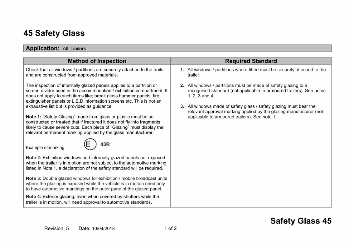
Safety Glass 45 Revision: 5 Date: 10/04/2018 1 of 2
45 Safety Glass Application: All Trailers
Method of Inspection Required Standard
Check that all windows / partitions are securely attached to the trailer and are constructed from approved materials. The inspection of internally glazed panels applies to a partition or screen divider used in the accommodation / exhibition compartment. It does not apply to such items like; break glass hammer panels, fire extinguisher panels or L.E.D information screens etc. This is not an exhaustive list but is provided as guidance. Note 1: “Safety Glazing” made from glass or plastic must be so constructed or treated that if fractured it does not fly into fragments likely to cause severe cuts. Each piece of “Glazing” must display the relevant permanent marking applied by the glass manufacturer. Example of marking Note 2: Exhibition windows and internally glazed panels not exposed when the trailer is in motion are not subject to the automotive marking listed in Note 1, a declaration of the safety standard will be required. Note 3: Double glazed windows for exhibition / mobile broadcast units where the glazing is exposed while the vehicle is in motion need only to have automotive markings on the outer pane of the glazed panel.
Note 4: Exterior glazing, even when covered by shutters while the trailer is in motion, will need approval to automotive standards.
1. All windows / partitions where fitted must be securely attached to the trailer.
2. All windows / partitions must be made of safety glazing to a
recognised standard (not applicable to armoured trailers). See notes 1, 2, 3 and 4.
3. All windows made of safety glass / safety glazing must bear the
relevant approval marking applied by the glazing manufacturer (not applicable to armoured trailers). See note 1.

Safety Glass 45 Revision: 5 Date: 10/04/2018 2 of 2
Record of Revision
Revision Date Description of Change
1 16/04/2009
2 28/02/2011 Add statement for partitions, delete note 2 and link note 1 to standards
3 30/04/2012 Add note 2 & 3, link to RS 2
4 29/10/2013 Insert new paragraph 3, shutters on windows.
5 10/04/2018 Reword RS & MOI

Tyres 46 Revision: 4 Date: 10/04/2018 1 of 6
46 Tyres Application: All Trailers
Method of Inspection Required Standard
Check each tyre for correct fitment, structure and that it has the correct markings to confirm compliance with the required standards. Where it is not possible to check markings, a declaration will be required from the applicant. Note 1: See comparable standards for O1/2 trailer tyres. Note 2: Tyres with no category of use designation (special, snow tyre etc), will be deemed to be Normal Use Tyres. Note 3: Structure means the technical characteristics of the tyres carcass, such as diagonal or bias ply, bias belted, Radial, reinforced. Note 4: Type of tyre means tyres which do not differ in such essential respects as Manufacturer’s name or trade mark, tyre size designation, category of use (special, snow tyre etc.), speed category, load capacity index and tyre cross section. Annex 1
1. Each tyre fitted to the trailer, including any spare or temporary use spare, must have the correct approval marks ‘E‘ or ‘e’, DOT or JIS (see note 1 & Annex 1).
2. The tyre must also be marked with the following information :-
Manufacturer’s name or trade mark, tyre size designation, category of use (as appropriate), speed category, load capacity index and tyre cross section. (See note 2).
3. Each of the tyres fitted to a trailer, must have the same structure.
(See note 3).
4. Each of the tyres fitted to any one axle must be of the same type. (See note 4).
5. Each tyre must have the correct load indices, speed ratings and
use markings, taking into account the vehicle to which it is fitted, and the type of use i.e. load and speeds the vehicle will be subject to. (See notes 2,3 & 4 also tables 1,2 & 4).
6. Each wheel and tyre must have sufficient room to revolve so as to
ensure that it is unlikely to foul on any part, taking into consideration the suspension and steering constraints provided by the manufacturer.
7. Tyres must be fitted in accordance with the manufacturer’s
instructions as indicated on the side wall of the tyre.

Tyres 46 Revision: 4 Date: 10/04/2018 2 of 6
Method of Inspection Required Standard
8. O1 and O2 trailers; the grooves of the tread pattern must be at least 1.6mm in depth throughout a continuous band comprising of the centre ¾ of the original breadth of the tread pattern (excluding wear indicators).
9. O3 and O4 trailers; the grooves of the tread pattern must be at least
1mm in depth throughout a continuous band comprising of at least ¾ of the original breadth of the tread pattern (excluding wear indicators).
10. O1 and O2 trailers fitted with passenger car tyres in single
formation, the maximum load rating of every tyre must be at least equal to 0.45 times the maximum mass for the most heavily loaded axle, as declared by the manufacturer of the trailer. For tyres in dual (twin) formation this factor is 0.24 (see table 3 for individual tyre load ratings).
The Minimum required speed ratings are:
Class of Trailer PERMITTED SPEED (MPH) MINIMUM SPEED SYMBOL Trailers 60 J Trailers operating under 2J or 2M tyre use conditions 40 D
Table 1
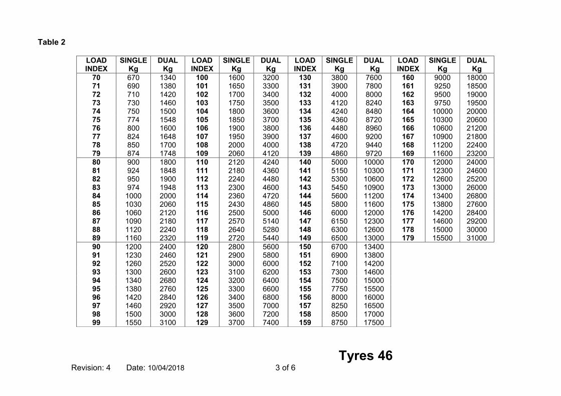
Tyres 46 Revision: 4 Date: 10/04/2018 3 of 6
Table 2
LOAD INDEX
SINGLE Kg
DUAL Kg
LOAD INDEX
SINGLE Kg
DUAL Kg
LOAD INDEX
SINGLE Kg
DUAL Kg
LOAD INDEX
SINGLE Kg
DUAL Kg
70 670 1340 100 1600 3200 130 3800 7600 160 9000 18000 71 690 1380 101 1650 3300 131 3900 7800 161 9250 18500 72 710 1420 102 1700 3400 132 4000 8000 162 9500 19000 73 730 1460 103 1750 3500 133 4120 8240 163 9750 19500 74 750 1500 104 1800 3600 134 4240 8480 164 10000 20000 75 774 1548 105 1850 3700 135 4360 8720 165 10300 20600 76 800 1600 106 1900 3800 136 4480 8960 166 10600 21200 77 824 1648 107 1950 3900 137 4600 9200 167 10900 21800 78 850 1700 108 2000 4000 138 4720 9440 168 11200 22400 79 874 1748 109 2060 4120 139 4860 9720 169 11600 23200 80 900 1800 110 2120 4240 140 5000 10000 170 12000 24000 81 924 1848 111 2180 4360 141 5150 10300 171 12300 24600 82 950 1900 112 2240 4480 142 5300 10600 172 12600 25200 83 974 1948 113 2300 4600 143 5450 10900 173 13000 26000 84 1000 2000 114 2360 4720 144 5600 11200 174 13400 26800 85 1030 2060 115 2430 4860 145 5800 11600 175 13800 27600 86 1060 2120 116 2500 5000 146 6000 12000 176 14200 28400 87 1090 2180 117 2570 5140 147 6150 12300 177 14600 29200 88 1120 2240 118 2640 5280 148 6300 12600 178 15000 30000 89 1160 2320 119 2720 5440 149 6500 13000 179 15500 31000 90 1200 2400 120 2800 5600 150 6700 13400 91 1230 2460 121 2900 5800 151 6900 13800 92 1260 2520 122 3000 6000 152 7100 14200 93 1300 2600 123 3100 6200 153 7300 14600 94 1340 2680 124 3200 6400 154 7500 15000 95 1380 2760 125 3300 6600 155 7750 15500 96 1420 2840 126 3400 6800 156 8000 16000 97 1460 2920 127 3500 7000 157 8250 16500 98 1500 3000 128 3600 7200 158 8500 17000 99 1550 3100 129 3700 7400 159 8750 17500

Tyres 46 Revision: 4 Date: 10/04/2018 4 of 6
Table 3
Load Index
Max KG Load Index
Max KG Load Index
Max KG Load Index
Max KG Load Index
Max KG Load Index
Max KG
0 45 35 121 70 335 105 925 140 2 500 168 5 600 1 46,2 36 125 71 345 106 950 141 2 575 169 5 800 2 47,5 37 128 72 355 107 975 142 2 650 170 6 000 3 48,7 38 132 73 365 108 1 000 143 2 725 171 6 150 4 50 39 136 74 375 109 1 030 144 2 800 172 6 300 5 51,5 40 140 75 387 110 1 060 145 2 900 173 6 500 6 53 41 145 76 400 111 1 090 146 3 000 174 6 700 7 54,5 42 150 77 412 112 1 120 147 3 075 175 6 900 8 56 43 155 78 425 113 1 150 148 3 150 176 7 100 9 58 44 160 79 437 114 1 180 149 3 250 177 7 300
10 60 45 165 80 450 115 1 215 150 3 350 178 7 500 11 61,5 46 170 81 462 116 1 250 151 3 450 179 7 750 12 63 47 175 82 475 117 1 285 152 3 550 180 8 000 13 65 48 180 83 487 118 1 320 153 3 650 181 8 250 14 67 49 185 84 500 119 1 360 154 3 750 182 8 500 15 69 50 190 85 515 120 1 400 155 3 875 183 8 750 16 71 51 195 86 530 121 1 450 156 4 000 184 9 000 17 73 52 200 87 545 122 1 500 157 4 125 185 9 250 18 75 53 206 88 560 123 1 550 158 4 250 186 9 500 19 77,5 54 212 89 580 124 1 600 159 4 375 187 9 750 20 80 55 218 90 600 125 1 650 160 4 500 188 10 000 21 82,5 56 224 91 615 126 1 700 161 4 625 189 10 300 22 85 57 230 92 630 127 1 750 162 4 750 190 10 600 23 87,5 58 236 93 650 128 1 800 163 4 875 191 10 900 24 90 59 240 94 670 129 1 850 164 5 000 192 11 200 25 92,5 60 250 95 690 130 1 900 165 5 150 193 11 500 26 95 61 257 96 710 131 1 950 160 4 500 194 11 800 27 97,5 62 265 97 730 132 2 000 161 4 625 195 12 150 28 100 63 272 98 750 133 2 060 162 4 750 196 12 500 29 103 64 280 99 775 134 2 120 163 4 875 197 12 850 30 106 65 290 100 800 135 2 180 164 5 000 198 13 200 31 109 66 300 101 825 136 2 240 165 5 150 199 13 600 32 112 67 307 102 850 137 2 300 160 4 500 200 14 000 33 115 68 315 103 875 138 2 360 166 5 300 34 118 69 325 104 900 139 2 430 167 5 450
Note: This indicates the maximum load each tyre can carry.

Tyres 46 Revision: 4 Date: 10/04/2018 5 of 6
Table 4 (for variation of load capacity for STGO)
Speed (km/h)
Variation of load capacity (%) All load indices Load indices
≥ 122 Load indices
≤ 121 Speed category symbol Speed
category symbol
Speed category symbol
F G J, K L, M L, M, N, P 0 + 150 + 150 + 150 + 150 + 110 5 + 110 + 110 + 110 + 110 + 90 10 + 80 + 80 + 80 + 80 + 75 15 + 65 + 65 + 65 + 65 + 60 20 + 50 + 50 + 50 + 50 + 50 25 + 35 + 35 + 35 + 35 + 42 30 + 25 + 25 + 25 + 25 + 35 35 + 19 + 19 + 19 + 19 + 29 40 + 15 + 15 + 15 + 15 + 25 45 + 13 + 13 + 13 + 13 + 22 50 + 12 + 12 + 12 + 12 + 20 55 + 11 + 11 + 11 + 11 + 17,5 60 + 10 + 10 + 10 + 10 + 15 65 + 7,5 + 8,5 + 8,5 + 8,5 + 13,5 70 + 5 + 7 + 7 + 7 + 12,5 75 + 2,5 + 5,5 + 5,5 + 5,5 + 11 80 0 + 4 + 4 + 4 + 10 85 − 3 +2 + 3 + 3 + 8,5

Tyres 46 Revision: 4 Date: 10/04/2018 6 of 6
Record of Revision
Revision Date Description of Change
1 16/04/2009
2 28/02/2011 Re word RS 08 and 09, link Table 3 to RS 10
3 29/10/2014 Add new tyre tables 1,2 and 4
4 10/04/2018 Reword section

Masses and Dimensions 48A Revision: 7 Date 10/04/2018 1 of 6
48A Masses and Dimensions Application: All Trailers
Method of Inspection Required Standard
This inspection is to ensure that the trailer as presented has satisfactory evidence of compliance to the required standard and has not been subject to modifications that may invalidate any approval held. In most cases a trailer submitted for test will be unladen and will be obviously well within the permissible weights set out in Annex 1 to section 18. However, if it seems likely that the trailer or an axle (as presented) exceeds any of these weights, the trailer should be weighed or a weight ticket requested. Trailers complying with the Road Vehicles (Authorisation of Special Types)(General) Order 2003 or the Motor Vehicles (Authorisation of Special Types) Order (Northern Ireland) 1997 are exempt from any of the standards which they are unable to comply with due to their special purpose. Plating: A Plating examination under the Goods Vehicle (Plating and Testing) Regulations 1988 must be carried out during the IVA examination, and a Plating certificate issued after the IVA certificate is issued. This does not apply in the case of trailers exempted from Plating, and trailers intended to be based in Northern Ireland. In these cases the Statutory Plate prescribed in Section 18 of this manual must have 2 columns, one for
Dimensions: 1. The trailer must not exceed the maximum authorised dimensions shown in the
table below. (See notes 1)
Category WIDTH See Annex 1
LENGTH See Annex 1
LENGTH FROM KINGPIN
O1 2550mm 7000mm (A) N/A
O2 2550mm (B) 7000mm(A) N/A
O1/2 Semi-Trailer 2550mm (B) 12200mm 2040mm
O3/O4 Rigid Trailer
2550mm (B) 12000mm N/A
O3/O4 Low Loader Semi-
Trailer
2550mm (B) 13500mm (C) 2040mm
O3/O4 Motor Vehicle
Transporter Semi-Trailer
2550mm 12500mm (C) 4190mm
Any other O3/O4 Semi-Trailer
2550mm (B) 12000mm (C) 2040mm
(A) Length of 12000mm is permitted, but only if the trailer is to be towed solely by vehicles with GVW exceeding 3500kg, in line with Regulation 7 of the Road Vehicles (Construction and Use) Regulations 1986 and in addition the trailer

Masses and Dimensions 48A Revision: 7 Date 10/04/2018 2 of 6
Method of Inspection Required Standard maximum GB/NI weights and one for maximum technically permissible weights (if different). Note 1: an O2 trailer can exceed 7000mm in length and be towed by a vehicle having a GVW of 3500kg or less if it is normally used to carry an indivisible load of exceptional length e.g. a boat or glider trailer. Note 2: Satisfactory documentary evidence or a declaration from the trailer assembler should be provided, stating that the trailer complies with this standard. Note 3: Check that the trailer combination is able to manoeuvre a complete circular trajectory of 360 degrees inside an area defined by two concentric circles, without any of the vehicles outermost points projecting outside the circumferences of the circles (See figure 1). This must be completed on both steering locks. The outer circle having a radius of 12.50 metres.
The inner circle having a radius of 5.30 metres. Note 4: A semi-trailer is deemed to comply with the requirements if its wheelbase is not greater than the sum below
22 )2/30.5()04.250.12( L The wheelbase being measured for the purpose of this section is the distance of the axis of the fifth-wheel king-pin to the centre line of the non steering axles bogie
L being the trailer width in metres
must have at least 4 wheels. (at least 2 axles) A trailer this size must be accompanied to test by a suitable towing vehicle, otherwise a refusal to test will be issued.(See note 1) (B) 2600mm for the superstructure of trailers designed for transport of goods under controlled temperatures and trailer caravans. (C) measured from the fifth-wheel king pin to the rear of the semi-trailer
2. The displayed dimensions as shown on the Dimensions plate (or
manufacturer’s plate, see section 18) must be within 5% of the trailer dimensions as presented.
Masses:
3. In the case of a trailer subject to Plating, the trailer or axle weights as presented must not exceed the maximums authorised to be issued on the Plating certificate. (See note 2)
4. In the case of a trailer not subject to Plating, the trailer or axle weights as
presented must not exceed the maximums marked on the Statutory Plate prescribed in section 18 of this manual. (See note 2).
5. For a trailer exceeding 3500kg gross weight, or a semi-trailer, it must be
verified that the trailer has a facility such that its power brakes can be operated by the towing vehicle.
Installation of retractable or loadable axles:
6. If a trailer is fitted with one or more loadable axles, satisfactory evidence must be provided stating that under all driving conditions, the axle will lower to the ground automatically when the front axle or the nearest axle of a group of axles is loaded. (See note 4).
Turning Circle Requirements: (O3 & O4 semi trailers only)

Masses and Dimensions 48A Revision: 7 Date 10/04/2018 3 of 6
Method of Inspection Required Standard Note 5: The following trailers are exempt from standard 7 A semi-trailer low loader. A semi-trailer step-frame low loader. Note 6: A Motor Vehicle transporter must comply with standard 7, except that any part of the semi-trailer forward of the transverse plane passing through the king pin may be ignored.
7. The trailer combination must be able to manoeuvre for a complete circular trajectory of 360 degrees within the defined area (with the exception of the protruding parts prescribed for the trailer width shown in Annex 1). (See notes 3 & 4,5,6 & figure 1).
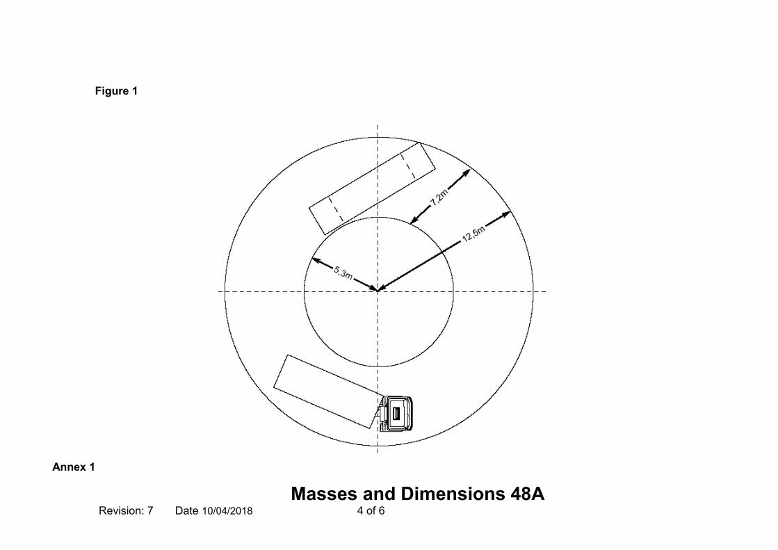
Masses and Dimensions 48A Revision: 7 Date 10/04/2018 4 of 6
Annex 1
Figure 1

Masses and Dimensions 48A Revision: 7 Date 10/04/2018 5 of 6
A - Items to be excluded when measuring Length B - Items to be excluded when measuring Width
—rear registration plates, — lighting equipment, (extendable light bars will be allowed and they are to be excluded from the overall length measurement (in there extended position) as long as these bars do not increase the load carrying capacity of the vehicle. DVSA will not accept them if they are fitted with any device that allows the attachment of a load i.e. twist locks) — access steps and hand-holds, — lifting platforms, access ramps and similar equipment in running order (i.e. in the position they would be on a moving trailer), not exceeding 300 mm, provided that the loading capacity of the trailer is not increased, see note below Note: Loading ramps of more than 300mm are permitted as long as the length of the trailer is reduced to accommodate this extra depth, (under no circumstances can these larger ramps be fitted to a trailer constructed to the maximum length as shown in table 1) i.e. An O4 semi-trailer requiring ramps of 450mm will need to reduce the maximum length from 12000mm to 11850mm. — coupling devices, - the drawbar or drawbeam can be classed as the coupling device and thus excluded when the measurement takes place (unless it has a function beyond being a coupling device - e.g. it has a box on it which carries a load). — wheel chocks on car transporters
— tyre-pressure or tyre failure indicators, — protruding flexible parts of wheel guards — lighting equipment, —access ramps in running order (i.e. in the position they would be on a moving trailer), provided that they do not exceed 10 mm from the side of the trailer, — retractable steps, — the deflected part of the tyre walls immediately above the point of contact with the ground, — handles and hinges of external lockers, — trim protruding not more than 10mm from the bodywork, — Devices for securing a tarpaulin/load cover and their protection. The edges shall be rounded to a radius of not less than 2,5 mm. — on trailer caravans: "slide-out" sections, — on trailer caravans: awnings (including their support arms), provided that any part more than 1m from the ground does not exceed 50mm, and any part more than 2m from the ground does not exceed 100mm, from the side of the vehicle.

Masses and Dimensions 48A Revision: 7 Date 10/04/2018 6 of 6
Record of Revision
Revision Date Description of Change
1 16/04/2009
2 28/02/2011 Add more items to width exemptions in Annex 1, link notes to standards and add new text to MOI
3 30/04/2012 Amend dimensions of trailer in table of RS 1
4 29/10/2012 Amend RS1 and add items to Annex 1B
5 29/10/2013 Insert new paragraph in MoI, amend notes 1, 2 & 8, update table in RS1 and Annexes 1A & B
6 29/10/2014 Rename section 48A, Amend MOI and Table 1 to accomdate the new sections 48B and 48C. Add new statement to Annex 1
7 10/04/2018 Notes 1, 2 & 7 amended, lighting equipment redefined in Annex 1, Table and notes revised

Masses and Dimensions AIL 48B Revision: 1 Date 29/10/2014 1 of 4
48B Masses and Dimensions: Over-length AIL Trailers Application: C&U trailers (P&T) of exceptional length which could also be dual plated for STGO usage as well.
Method of Inspection Required Standard
This inspection is to ensure that the trailer as presented has satisfactory evidence of compliance to the required standard and has not been subject to modifications that may invalidate any approval held. A Plating examination under the Goods Vehicle (Plating and Testing) Regulations 1988 may be carried out during the IVA examination, and a Plating certificate issued after the IVA certificate is issued. This does not apply in the case of trailers exempted from Plating, and trailers intended to be based in Northern Ireland. In these cases the Statutory Plate prescribed in Section 18 of this manual must have 2 columns, one for maximum GB/NI weights and one for maximum technically permissible weights (if different). Note 1: There is no length limit for a trailer constructed to carry indivisible loads of exceptional length, although the combination (trailer plus towing vehicle) cannot exceed 27.4m under C&U regulations. Note 2: An indivisible load is a load that cannot without undue expense or risk of damage be divided into two or more loads for the purpose of being carried on a road, and cannot on account of its length be safely carried on a trailer which is 12m long. Note 3: The Statutory Plate should contain the text at RS 7 of section 18.
Dimensions:
1. The trailer must not exceed the maximum authorised dimensions shown in the table below. (See notes 1 & 2)
Category WIDTH
See Annex 1 LENGTH
See Annex 1
Standard 2550mm 27400mm See Note 1
2. The displayed dimensions as shown on the Dimensions plate (or manufacturer’s plate, see section 18) must be within 5% of the trailer dimensions as presented, and width must not exceed 2550mm. See note 3.
Masses:
3. In the case of a trailer subject to Plating, the trailer or axle weights as presented must not exceed the maximums authorised to be issued on the Plating certificate. See note 4.
4. In the case of a trailer not subject to Plating, the trailer or axle weights as
presented must not exceed the maximums marked on the Statutory Plate prescribed in section 18 of this manual. See note 4.
5. For a trailer exceeding 3500kg gross weight, or a semi-trailer, it must be
verified that the trailer has a facility such that its power brakes can be operated by the towing vehicle.

Masses and Dimensions AIL 48B Revision: 1 Date 29/10/2014 2 of 4
Method of Inspection Required Standard Note 4: In most cases a trailer submitted for test will be unladen and will be obviously well within the permissible weights set out in Annex 1 to section 18. However, if it seems likely that the trailer or an axle (as presented) exceeds any of these weights, the trailer should be weighed or a weight ticket requested. . Note 5: Satisfactory documentary evidence or a declaration from the trailer assembler should be provided, stating that the trailer complies with this standard.
Installation of retractable or loadable axles:
6. If a trailer is fitted with one or more loadable axles, satisfactory evidence must be provided stating that under all driving conditions, the axle will lower to the ground automatically when the front axle or the nearest axle of a group of axles is loaded. See note 5.

Masses and Dimensions AIL 48B Revision: 1 Date 29/10/2014 3 of 4
Record of Revision
Revision Date Description of Change
1 29/10/2014 New Section

Masses and Dimensions AIL 48B Revision: 1 Date 29/10/2014 4 of 4
This page intentionally left blank

Masses and Dimensions: STGO 48C Revision: 1 Date 29/10/2014 1 of 2
48C Masses and Dimensions: STGO over-width or over-width and over-length Application: Wide or wide and long trailers, capable of STGO Cat 1, Cat 2 and/or Cat 3 operation. Not plated
Method of Inspection Required Standard
This inspection is to ensure that the trailer as presented has satisfactory evidence of compliance to the required standard and has not been subject to modifications that may invalidate any approval held. Note 1: For a ‘wide’ trailer the width must be 2551mm or greater. The Statutory Plate should contain the text at RS 8 of section18. Note 2: In most cases a trailer submitted for test will be unladen and will be obviously well within the permissible weights set out in Annex 1 to section 18. However, if it seems likely that the trailer or an axle (as presented) exceeds any of these weights, the trailer should be weighed or a weight ticket requested. . Note 3: Satisfactory documentary evidence or a declaration from the trailer assembler should be provided, stating that the trailer complies with this standard.
Dimensions:
1. The trailer must not exceed the maximum authorised dimensions shown in the table below.
Category WIDTH See Annex 1
LENGTH See Annex 1
Large 6100mm 30000mm
Extreme O4 (A) (A) (A)These vehicles will be assessed on a case by case basis and can be outside of the maximum dimensions requirements of ‘Large’
2. The displayed dimensions as shown on the Dimensions plate (or manufacturer’s plate, see
section 18) must be within 5% of the trailer dimensions as presented, and must not be below the regulated legal limits. See note 1.
Masses:
3. The trailer or axle weights as presented must not exceed the maximums marked on the Statutory Plate prescribed in section 18 of this manual. See note 2.
Installation of retractable or loadable axles:
4. If a trailer is fitted with one or more loadable axles, satisfactory evidence must be provided stating that under all driving conditions, the axle will lower to the ground automatically when the front axle or the nearest axle of a group of axles is loaded. See note 3.

Masses and Dimensions: STGO 48C Revision: 1 Date 29/10/2014 2 of 2
Record of Revision Revision Date Description of Change
1 29/10/2014 New Section

Masses and Dimensions: Engineering Plant 48D Revision: 1 Date 01/09/2018 1 of 2
48D Masses and Dimensions: Engineering Plant Application: All Engineering Plant Trailers
Method of Inspection Required Standard
This inspection is to ensure that the trailer as presented has satisfactory evidence of compliance to the required standard and has not been subject to modifications that may invalidate any approval held. Note 1: For a ‘wide’ trailer the width must be 2551mm or greater. The Statutory Plate should contain the text at RS 8 of section18. Note 2: In most cases a trailer submitted for test will be unladen and will be obviously well within the permissible weights set out in Annex 1 to section 18. However, if it seems likely that the trailer or an axle (as presented) exceeds any of these weights, the trailer should be weighed or a weight ticket requested. . Note 3: Satisfactory documentary evidence or a declaration from the trailer assembler should be provided, stating that the trailer complies with this standard.
Dimensions:
1. The trailer must not exceed the maximum authorised dimensions shown in the table below.
Category WIDTH
See Annex 1 LENGTH
See Annex 1 Large 6100mm 30000mm
Extreme O4 (A) (A) (A)These vehicles will be assessed on a case by case basis and can be outside of the maximum dimensions requirements of ‘Large’
2. The displayed dimensions as shown on the Dimensions plate (or manufacturer’s
plate, see section 18) must be within 5% of the trailer dimensions as presented, and must not be below the regulated legal limits. See note 1.
Masses:
3. The trailer or axle weights as presented must not exceed the maximums marked on the Statutory Plate prescribed in section 18 of this manual. See note 2.
Installation of retractable or loadable axles:
4. If a trailer is fitted with one or more loadable axles, satisfactory evidence must be provided stating that under all driving conditions, the axle will lower to the ground automatically when the front axle or the nearest axle of a group of axles is loaded. See note 3.

Masses and Dimensions: Engineering Plant 48D Revision: 1 Date 01/09/2018 2 of 2
Record of Revision
Revision Date Description of Change
1 01/09/18 New Section
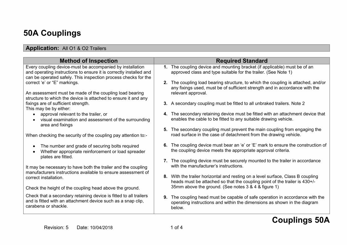
Couplings 50A Revision: 5 Date: 10/04/2018 1 of 4
50A Couplings Application: All O1 & O2 Trailers
Method of Inspection Required Standard
Every coupling device must be accompanied by installation and operating instructions to ensure it is correctly installed and can be operated safely. This inspection process checks for the correct ‘e’ or “E” markings. An assessment must be made of the coupling load bearing structure to which the device is attached to ensure it and any fixings are of sufficient strength. This may be by either:
approval relevant to the trailer, or visual examination and assessment of the surrounding
area and fixings When checking the security of the coupling pay attention to:-
The number and grade of securing bolts required Whether appropriate reinforcement or load spreader
plates are fitted. It may be necessary to have both the trailer and the coupling manufacturers instructions available to ensure assessment of correct installation. Check the height of the coupling head above the ground.
Check that a secondary retaining device is fitted to all trailers and is fitted with an attachment device such as a snap clip, carabena or shackle.
1. The coupling device and mounting bracket (if applicable) must be of an approved class and type suitable for the trailer. (See Note 1)
2. The coupling load bearing structure, to which the coupling is attached, and/or any fixings used, must be of sufficient strength and in accordance with the relevant approval.
3. A secondary coupling must be fitted to all unbraked trailers. Note 2
4. The secondary retaining device must be fitted with an attachment device that
enables the cable to be fitted to any suitable drawing vehicle.
5. The secondary coupling must prevent the main coupling from engaging the road surface in the case of detachment from the drawing vehicle.
6. The coupling device must bear an ‘e’ or ‘E’ mark to ensure the construction of
the coupling device meets the appropriate approval criteria.
7. The coupling device must be securely mounted to the trailer in accordance with the manufacturer’s instructions.
8. With the trailer horizontal and resting on a level surface, Class B coupling
heads must be attached so that the coupling point of the trailer is 430+/- 35mm above the ground. (See notes 3 & 4 & figure 1)
9. The coupling head must be capable of safe operation in accordance with the
operating instructions and within the dimensions as shown in the diagram below.

Couplings 50A Revision: 5 Date: 10/04/2018 2 of 4
Method of Inspection Required Standard Check that the coupling head can be operated safely within the free space of the coupling ball shown in diagram in standards. Note 1: Check that the correct type of coupling head is fitted to the trailer, normally this will be Class B (50mm ball), Class D (eye) but Class S (non standard) is also acceptable. Note 2: A secondary coupling can only be used on braked trailers not fitted with a breakaway cable with a maximum mass not exceeding 1.5 tonnes. This cable attaches the trailer to the towing vehicle whilst towing and provides a secondary link. A secondary coupling is a legal requirement for all unbraked trailers. Note 3: In the case of caravans and goods trailers, the horizontal position is regarded as when the floor or loading surface is horizontal. In the case of trailers without such a reference surface, the trailer manufacturer must give an appropriate reference line defining the horizontal position. Note 4: In the case of trailers designed and constructed for use with ‘off road’ vehicles this measurement does not apply (evidence will be requested). Semi Trailers Note 5: The coupling device must be accompanied by installation instructions from the trailer manufacturer and / or manufacturer of the fifth wheel pin, to ensure it is correctly installed.
10. Any over-run coupling must be positioned correctly on the drawbar to allow
the maximum travel to be achievable without obstruction. (See example in Figure 2).
Figure 1
Figure 2
Maximum Travel of slider
Extended length of slider
Semi Trailers
11.The fixing of the fifth wheel coupling pin in the mounting plate on the semi –trailer must be as instructed by the trailer manufacturer and / or manufacturer of the fifth wheel pin. (See notes 5 & 6).

Couplings 50A Revision: 5 Date: 10/04/2018 3 of 4
Method of Inspection Required Standard Note 6: It may not be possible to fully examine the installation of a fifth wheel coupling pin. In these cases documentary evidence of compliance will be required
12. Semi-trailers must be equipped with secure landing gear or other equipment to allow safe uncoupling and parking.

Couplings 50A Revision: 5 Date: 10/04/2018 4 of 4
Record of Revision
Revision Date Description of Change
1 16/04/2009
2 30/04/2012 Add Note 5, add new acceptable category of coupling head in MoI
3 29/10/2012 Amend paragraphs 2 & 3 in the MoI, revise note numbering, amend tolerance in RS7 & Figure 1 and Add Semi trailer details
4 29/10/2013 Amend RS7, insert new RS9 and Figure 2
5 10/04/2018 Insert new MOI & RS regarding structure assessment

Couplings 50B Revision: 3 Date: 10/04/2018 1 of 4
50B Couplings Application: All O3 & O4 Trailers
Method of Inspection Required Standard
This inspection is to ensure that the coupling device is of an approved type, has the correct markings, and is accompanied by manufacturer’s installation instructions. Semi trailer support gear (i.e. landing legs) and draw bar adjusting devices should be checked for compliance with RS 4 for semi trailers and RS 6 for drawbar. An assessment must be made of the coupling load bearing structure to which the device is attached to ensure it and any fixings are of sufficient strength. This may be by either:
approval relevant to the trailer, or visual examination and assessment of the surrounding area and
fixings Note 1: The coupling device must be accompanied by installation instructions from the trailer manufacturer and / or manufacturer of the fifth wheel pin, to ensure it is correctly installed. Note 2: It may not be possible to fully examine the installation of a fifth wheel coupling pin. In these cases documentary evidence of compliance will be required. Note 3: STGO - Abnormal Indivisible Load Vehicles (GTW of at least 120,000kg), the couplings are not required to be ‘e’ or ‘E’ marked. Note 4: For STGO Modular trailers only, the coupling device may be a device at either or both ends of trailer intended to attach towing/bridging devices on modular type trailers or to link modular type trailers together
1. The coupling device must bear an ‘e’ or ‘E’ mark, and be accompanied by relevant installation instructions. (See note 1, 2,3 & 4).
2. The coupling device must be designed to work safely at the Max
GB gross weight of the trailer, as identified in section 18 of this manual.
3. The coupling load bearing structure, to which the coupling is attached, and/or any fixings used, must be of sufficient strength and in accordance with the relevant approval.
Semi Trailers
4. The fixing of the fifth wheel coupling pin in the mounting plate on
the semi –trailer must be as instructed by the trailer manufacturer and / or manufacturer of the fifth wheel pin. (See note 1 & 2).
5. Semi trailers must be equipped with secure landing gear or other
equipment to allow safe uncoupling and parking. Drawbar Trailers 6. The fixing of the drawbar eye onto the drawbar frame must be as
instructed by the trailer manufacturer and / or manufacturer of the draw bar eye.

Couplings 50B Revision: 3 Date: 10/04/2018 2 of 4
Method of Inspection Required Standard
7. The drawbar eye or coupling head on hinged drawbars must rest at least 200mm from the ground when released from the horizontal position.
8. If a hinged drawbar is equipped with a device for adjusting the
drawbar to the height of the coupling. The device must be able to be operated by one person without any tools or other aids.
9. For height adjusting devices that provide adjustment for at least
300mm upwards and downwards from the horizontal then the drawbar must be adjustable in steps no greater than 50mm at the coupling or eye.
10. The height adjusting device must not interfere with easy
movement of the drawbar after coupling.

Couplings 50B Revision: 3 Date: 10/04/2018 3 of 4
Record of Revision
Revision Date Description of Change
1 16/04/2009
2 28/02/2011 Reword note 2 and link standards to notes
3 10/04/2018 Notes 3 & 4 added`& addition of coupling strength assessment

Couplings 50B Revision: 3 Date: 10/04/2018 4 of 4
This page intentionally left blank

General Construction Revision: 4 Date: 10/04/2018 1 of 2
General Construction Application: All Trailers subject to IVA requirements
Method of Inspection Required Standard
The following section assesses the trailers suitability for use under all normal operating conditions, including when it is laden to its maximum permitted axle/gross vehicle weight and considers the effects of vibrations and the forces imposed by its design speed, acceleration characteristics, braking and cornering. The trailer at all times must present no danger to other road users. All components and attachment methods will be compared to those employed on ECWVTA trailers. This does not prevent a manufacturer utilising other construction methods or materials providing they offer at least the equivalent performance of those employed on an approved trailer. Note 1 This assessment includes any form of attachments of any component or the assembly of a structure itself, the strength and suitability of materials used including pipes etc. and any fastening, welds, bonding, rivets, nuts and bolts etc. are to be assessed for their ability to perform their function as intended and must be suitable, complete and fully secured as intended. Note 2 When assessing a component for leaks the original design of the component will be taken into consideration.
Note 3: This does not apply to control leads (fly leads) used on specialised equipment i.e. power ramps and lifts.
1. All aspects of the design and construction of the trailer must be such that no Immediate danger is caused or likely to be caused to any person in the trailer or to other road users.
2. When towed, the safe control of the trailer or its towing vehicle must not be
impaired or likely to be impaired, due to a design or construction feature of characteristic.
3. The trailer structure and all components including their attachment must be
suitable and of adequate strength. (See note 1).
4. A transmission/braking component which rotates during vehicle operation, electrical component, steering or suspension component, wheel or tyre must not foul on another component, or be likely to foul under normal operating conditions.
5. Fuel and electrical components must not be subject to either a corrosive
environment or be exposed to heat sources likely to cause premature failure.
6. All steering, suspension, braking and fuel system components must not be leaking. (See note 2).
7. All electrical cables/wires must be free from chaffing and secured at intervals
of at least every 300mm unless contained in a secure hollow component. (See note 3).
8. All electrical components must be of adequate capacity and insulated as
required as to prevent short circuiting during operation.

General Construction Revision: 4 Date: 10/04/2018 2 of 2
Record of Revision
Revision Date Description of Change
1 16/04/2009
2 28/02/2011 Add new RS1 and add note 3
3 29/10/2012 Amend RS6
4 10/04/2018 Amend MOI align with N2/3

IVA O1-O4 Inspection Manual Document uncontrolled when printed
Glossary of Terms Revision: 7 Date: 01/09/2018 1 of 6
Glossary of Terms Abnormal Indivisible Load Trailer A trailer specially designed and constructed, and used only for, or empty in connection with, the conveyance of abnormal indivisible loads. Approval Authority The Vehicle Certification Agency are the UK Approval Authority. Auxiliary engine An engine not used to propel the vehicle but to drive engineering plant equipment on the vehicle. Blunted Edge An edge not likely to cause injury whatever the circumstances under finger/thumb pressure (contact is not likely to puncture the skin). Breakaway Cable A legally required safety device that activates the brakes if car and trailer / caravan become separated in transit. It works by pulling the brakes on then snapping. CNG Compressed Natural Gas. Centre Axle Trailer A trailer having only a single axle or group of axles which is positioned at or close to the centre of gravity so that, when the trailer is uniformly loaded, the static vertical load transmitted to the towing vehicle does not exceed 10 per cent of the maximum authorised weight for the axle or group of axles or 1,000kg, whichever is the less. Coupling Class Class A = Coupling balls and towing brackets Class B = Coupling heads Class C = Automatic drawbar couplings Class D = Drawbar eyes Class G = Fifth wheel Couplings Class H = Fifth wheel pin Class S = Devices and components which do not conform to any of the Classes A to H above and which are used, for example, for special heavy transport or are devices unique to some countries and covered by existing national standards.

IVA O1-O4 Inspection Manual Document uncontrolled when printed
Glossary of Terms Revision: 7 Date: 01/09/2018 2 of 6
Date of Manufacture In the case of an Amateur Built Trailer is, unless otherwise stated in the regulations or Inspection Manual: the date on which the trailer is presented for examination;
or
a date prior to the date the trailer is presented for examination if there is conclusive evidence the trailer was completed and included all the parts which it needs to comply with the prescribed requirements and was in such a condition as to be acceptable to test on that date.
Draw Bar Trailer Trailer with an inbuilt steering mechanism on the front axle. Double Glazing An assembly of two glazing panes permanently assembled in manufacture and separated by a uniform gap. Double Windows Two separate units installed in a vehicle as separate inner and outer panes. Engineering Plant Movable plant or equipment being a motor vehicle or trailer specially designed and constructed for the special purposes of engineering operations, and which cannot, owing to the requirements of those purposes comply with all the requirements. Extreme Outer Edge In relation to the side of a trailer, the vertical plane parallel with the longitudinal axis of the trailer and coinciding with its lateral outer edge, disregard the projection of
distortion of any tyre due to the weight of the trailer connections for tyre pressure gauges anti-skid devices mounted on the wheels
lamps and reflectors

IVA O1-O4 Inspection Manual Document uncontrolled when printed
Glossary of Terms Revision: 7 Date: 01/09/2018 3 of 6
custom seals and devices for securing and protecting such seals
special equipment (as listed in Annex 1 section 48) Foundation Brake
The foundation brake is the basic drum or disc brake assembly fitted to each axle or wheel which produces the braking force necessary to bring the trailer to a stop. Indivisible load Shall mean a load that cannot, for the purpose of carriage by road, be divided into two or more loads without undue expense or risk of damage. Illuminating Surface Should be taken to be the area of the “reflector” to the rear of the bulbs. Where lamps are mounted in a common housing and are “E” marked, the separation criteria should be assumed to be met.
Insecure A component or its fixing is, due to its design or a construction feature, not completely attached to the trailer structure or to another associated component as intended. Lifting Axle ‘Lifting axle’ means an axle which can be lifted from the road during normal trailer use. Longitudinal Plane A vertical plane parallel to the longitudinal axis of the trailer. Low Loader Trailer A semi-trailer which is constructed and normally used for the carriage of engineering equipment so constructed that the major part of the load platform does not extend over or between the wheels and the upper surface of which is below the height of the top most point of the tyres of those wheels. LPG Liquid Petroleum Gas Major Manufacturer

IVA O1-O4 Inspection Manual Document uncontrolled when printed
Glossary of Terms Revision: 7 Date: 01/09/2018 4 of 6
A vehicle manufacturer that produces vehicles approved to EC Whole Vehicle Type Approval standards. Manufacturer’s Plate A piece of durable material e.g. metal or plastic that is likely to last the life of the trailer and which is permanently marked with the required markings. Matched Pair For the purpose of this manual only: Lamps fitted to the vehicle must be of the same brightness, intensity, colour, shape, height and position. Obvious modification Where evidence suggests that the vehicle / component has been modified which invalidates the approval, evidence must be easily recognisable without the need of a detailed inspection. Overrun Braking The motion of the trailer with respect to the towing vehicle is used to actuate the brake. Passenger Car tyre A tyre designed primarily, but not only, for passenger cars (motor vehicles in Category M1) and their trailers (01 and 02)". Production Vehicle A vehicle of a make, model and type, mass produced by the vehicle manufacturer. Rain flap ‘Rain flap’ means a flexible component mounted vertically behind the wheel, on the lower part of the chassis or the loading surface, or on the mudguard. Rigid Draw Bar Trailer See centre axle trailer Secondary coupling This cable attaches the trailer to the towing vehicle whilst towing and provides a secondary link. A secondary coupling is a legal requirement for all un-braked trailers and braked trailers not exceeding 1500kgs. Step Frame Trailer

IVA O1-O4 Inspection Manual Document uncontrolled when printed
Glossary of Terms Revision: 7 Date: 01/09/2018 5 of 6
A semi-trailer (not being a low loader) which is constructed and normally used for the carriage of engineering equipment and is so constructed that the upper surface of the major part of the load platform is at a height of less than 1m above the ground when measured on level ground. Teardrop Trailer or Caravan A compact lightweight travel trailer which gets its name from its teardrop profile. To be considered a caravan (SPV) it must genuinely provide 'mobile living accommodation'. Unladen weight The unladen weight of any trailer is the weight of the trailer excluding, goods or other items. It includes the body and all parts normally used with the vehicle or trailer when in use on the road.

IVA O1-O4 Inspection Manual Document uncontrolled when printed
Glossary of Terms Revision: 7 Date: 01/09/2018 6 of 6
Record of Revision
Revision Date Description of Change
1 16/04/2009
2 28/02/2011 Add definitions
3 30/04/2012 Add definition for Class S coupling
4 29/10/2013 Insert new definitions identified by vertical line in the left hand column
5 29/10/2014 Insert new definitions for Low Loader and Step Frame Low Loader
6 10/04/2018 Amend/add definitions.
7 01/09/2018 Definition of Engineering Plant added.