individual construction notesdot.nebraska.gov/media/6760/construction-notes.pdf · 2016-11-23 ·...
TRANSCRIPT

INDIVIDUAL CONSTRUCTION NOTES
JANUARY 2007
ROADWAY
Nebraska Department of Roads
ESIGND

SECTION A GENERAL NOTES
SECTION B GUARDRAIL NOTES
SECTION C1
SECTION
CONCRETE NOTES
C2
SECTION D
SECTION E
SECTION F
SEWER NOTESSECTION G
REMOVAL NOTESSECTION H
J BRIDGE NOTESSECTION
INDEX OF INDIVIDUAL NOTES
CULVERT NOTES
JANUARY 2007
Attenuators, Cable Guardrail, Inertial Barriers,
Thrie-Beam Guardrail, Safety Beam Guardrail
and W-Beam Guardrail
Asphaltic Curb, Delineators, Dikes, Erosion Control
Existing Railroad, Fence and Silt Checks
Approach Slabs, Curb, Ditch Lining, Drives, Flumes,
Gutters, Islands, Patching, Repair and Retaining
Walls.
Driveway Culvert Pipe, Earth Drives and Gravel
Surfaces
Corrugated Metal Pipe, Earthwork Measured
Embankment and Temporary Surfacing
Phasing Legend
Area Inlet, Curb Inlet, Junction Box, Median Inlet,
Round Equivalent Sewer Pipe and Reinforced
Concrete Sewer Pipe
Asphaltic Surface, Abandon Well, Building, Clear Tract,
Curb, Concrete Barrier Discharge Structure, Ditch Liner,
Fence, Gutter, Guard Post, Guardrail, Pavement & Walk,
Concrete Deck, Concrete Slab, Continuous Girder
Deck Steel, Dbl. Tee Beam, Dbl. Pre stressed Girder,
Pre stressed Girder, Steel Girder, Temporary
RURAL DRIVES & INTERSECTION NOTES
Culvert Pipe, Crossovers, Flumes, Railroads, Rural
Drives, Sewers and Culvert Pipe Legend
MEDIAN X-OVERS, MAINT. TURNAROUND, TEMPORARY
ROAD’S AND TEMPORARY SURFACING NOTES
Concrete Box Culverts, Corrugated Metal Pipe,
Miscellaneous Pipe, Optional Pipe and Reinforced
Concrete Pipe, Miscellaneous Preliminary Pipe notes
PIPE POLICY NOTES

ADDITIONAL NOTES
SHEET NUMBER ADDITIONAL NOTE

GENERAL NOTES SHEET INDEX
SHEET
SHEET
SHEET
SHEET
SHEET
SECTION A GENERAL NOTES
SHEET
A01 - Existing Railroad Tracks Raised
A02 - Existing Railroad Tracks Lowered
A03 - Intercepting Dike
A04 - Earth Dike
A05 - Chain Link Fence
A06 - Delineators and Chevrons
A07 - Flexible Post Delineators
A08 - Rock Riprap
A09 - Broken Concrete Riprap
A10 - Riprap
A11 - Asphaltic Concrete Curb
A12 - Asphaltic Concrete Island Curb
A13 - Asphaltic Concrete Island Nose
A14 - Asphaltic Concrete Median Surfacing
SHEET
SHEET
SHEET
SHEET 10-A
A15 - Fabric Silt Fence
A16 - Fabric Silt Fence-High Porosity
A17 - Fabric Silt Fence, Type "Coir Fiber"
A18 - Fabric Silt Fence-Low Porosity
A19 - Fabric Silt Fence-Low Profile High Porosity
A30 - Slope Protection Netting
A31 - Area Inlet Sediment Filter
A32 - Inlet Liner
A20 - Fabric Silt Fence-Low Profile Low Porosity
A21 - Fabric Silt Fence-High Porosity, Type "ST"
A22 - Fabric Silt Fence-Low Porsity, Type "ST"
A23 - Erosion Checks
A24 - Fabric Silt Checks
A25 - Temporary Silt Checks
A26 - Erosion Control, Type "__"
A27 - Erosion Control
A28 - Erosion Control Soil Grid Confinement System
A29 - Temporary Erosion Control
BRGR STD.CEL
"DETAILS NOT SHOWN" CELLS
COMMON OMMISSIONS
ALIGNMENT INFORMATION
Erosion Control Information and Abbreviations
SHEET NO. 1-A
GENERAL NOTES LIST
GENERAL NOTES SHEET INDEX1-A
2-A
3-A
4-A
5-A
6-A
7-A
8-A
9-A

SECTION A GENERAL NOTES
GENERAL NOTES LIST
A01 - Existing Railroad Tracks Raised
A02 - Existing Railroad Tracks Lowered
A03 - Intercepting Dike
A04 - Earth Dike
A05 - Chain Link Fence
A06 - Delineators and Chevrons
A07 - Flexible Post Delineators
A08 - Rock Riprap
A09 - Broken Concrete Riprap
A10 - Riprap
A11 - Asphaltic Concrete Curb
A12 - Asphaltic Concrete Island Curb
A13 - Asphaltic Concrete Island Nose
A14 - Asphaltic Concrete Median Surfacing
A15 - Fabric Silt Fence
A16 - Fabric Silt Fence-High Porosity
A17 - Fabric Silt Fence, Type "Coir Fiber"
A18 - Fabric Silt Fence-Low Porosity
A19 - Fabric Silt Fence-Low Profile High Porosity
A20 - Fabric Silt Fence-Low Profile Low Porosity
A21 - Fabric Silt Fence-High Porosity, Type "ST"
A22 - Fabric Silt Fence-Low Porosity, Type "ST"
A23 - Erosion Checks
A24 - Fabric Silt Checks
A25 - Temporary Silt Checks
A26 - Erosion Control, Type "__"
A27 - Erosion Control
A28 - Erosion Control Soil Grid Confinement System
A29 - Temporary Erosion Control
A30 - Slope Protection Netting
A31 - Area Inlet Sediment Filter
A32 - Inlet Liner
SHEET NO. 2-A

ALIGNMENT INFORMATION ONLY
DNSL
STD.CEL
STD.CEL
BRGR
COMMON OMISSION:
INFORMATION ONLY CELL NAME
SECTION A GENERAL NOTES
STD.CEL
2H
DNSNSTD.CEL
DNSTSTD.CEL
DNSC
STD.CEL
DNSH
STD.CEL
All horizontal curves of 0^ 30’ or
greater requires a superelevation.
For small deflection angles, curves
should be long enough to avoid the
appearances of kinks and should
be at least 500 ft. long. The
degree of curvature should not be
less than 0^ 15’.
Include the boxed note "DNSL" on any Plan or Plan &
Profile Sheets when 2-L Sheets are covering an area in
more detail.
Include the boxed note "DNSN" on any Plan or Plan &
Profile Sheets when more information or a sketch is
located on the 2-N (General Info.) Sheet.
Where new pavement becomes contiguous with existing
pavement, it is not necessary to note on the plans:
’’Match Existing Grades’’.
Any change in direction with a deflection angle of 1^
or greater will require a horizontal curve.
NOTE: When modifying any of these "DNS" notes, do not
change the width of the box, instead, add another line
of text and adjust the height of the box.
If a Temporary Road is visible on a Mainline Plan &
Profile Sheet, and it has it’s own Plan & Profile
Sheet, include the boxed note "DNST".
If an Intersecting or Adjacent Highway is visible on a
Mainline Plan & Profile Sheet, and it has it’s own
Plan & Profile Sheet, include the boxed note "DNSH".
If an Intersecting or Adjacent County Road is visible
on a Mainline Plan & Profile Sheet, and it has it’s
own Plan & Profile Sheet, include the boxed note "DNSC".
STD.CEL
DNDT Current NDOR policy requires
a 14 ft. width (2 ft. pavement
widening) for inside lane of
horizontal curves if:
- The degree of curvature is greater than 3^;
- The operating speed is 45 mph or greater;
- The roadway does not have surfaced shoulders;
- Projected average daily truck traffic is more
than 50 per day.
For Details not shown see Sheet 2-L
For Details not shown see Sheet 2-N
On the Plan & Profile Sheet, show the profile
for the Bridge Rail & below bridge for:
the existing channel
the new embankment
the new grading
Include the boxed note "BRGR" on the Plan & Profile
Sheets when embankment is detailed on the Bridge Plans
2-N Sheet: Add "Curb Inlet Detail" if there are curb
inlets on the project.
2-T Sheet: Add "Concrete Pavement Repair Details" if
applicable.
SHEET NO. 3-A
Place Horizontally on Plan Portion
of Plan & Profile Sheet.
Place Horizontally on Plan Portion
of Plan & Profile Sheet.
Place Horizontally on Plan Portion of Sheet.
Place Horizontally on Plan Portion
of Plan & Profile Sheet.
Place Horizontally on Plan Portion
of Plan & Profile Sheet.
Place Horizontally on Plan Portion of Sheet.
Place Horizontally on Profile Portion
of Plan & Profile Sheet. (Where applicable)
Place Horizontally on Plan Portion
of Plan & Profile Sheet.
For Details of Grading Section at
Bridge Site, see Special Plan *.
For Details not shown see Temporary
Road Plan & Profile Sheet
For Details not shown see County Road
Plan & Profile Sheet
For Details not shown see Highway __
Plan & Profile Sheet
Information for all stationed Horizontal
Alignments are shown on Sheet 2-H.
STA. ___+__ TO STA. ___+__ ON RT.
DO NOT DISTURB TREES.

INFORMATION ONLY CELL NAME
A01
A02
A03
A04
A05
A06
Sta. ___+__ to
Sta. ___+__ Rt.
Build Intercepting Dike, as
Shown by Sketch on
Sheet 2-N.
Sta. ___+__
The Existing R.R. Tracks are
to Be Lowered __’ By Others.
Sta. ___+__
The Existing R.R. Tracks are
to Be Raised __’ By Others.
Sta. ___+__
Build Earth Dike to
Elev. ___.__, as Shown by
Sketch on Sheet 2-N.
Sta. ___+__ to
Sta. ___+__ Lt.
Build Highway Delineators,
Type __. S=__’; __-Each
& Install __-Chevrons.
Plan 901-R_.
Sta. ___+__ to
Sta. ___+__ Lt.
Build __ Lin. Ft. of _’ Chain
Link Fence. Plan 710-R_.
SECTION A GENERAL NOTES
An Intercepting Dike parallels the roadway and
an Earth Dike is transverse to a ditch.
Inform Drafting if a sketch will be required on the
2-T Sheet showing a longitudinal section of the
highway at the R.R. X-ing. It may be req’d. to show
Pavement Haunches if Concrete is less than 11"
(Asphalt projects do not require a sketch).
See Standard Detail 8350 5 E 01 for an example.
Normally, Delineators and Chevrons will not
be required on curves of less than 1^.
Refer to Standard Plan 901-R_, for spacing and
locations of chevrons and delineators.
DIKE TYPICAL SECTION DETAILS
For an "Earth Dike" use the "edike" cell.
For an Intercepting Dike use the "dike" cell.
Both cells are found in the mast.cel cell library.
Sheet 2-N is a General Information Sheet.
(Shows Legend for Survey Symbols, Standard Notes,
Sketches, Etc.)
A07Sta. ___+__ to
Sta. ___+__ Rt.
Build Flexible Post Delineators
S=__’, __-Each. Plan 901-R_
and Special Plan _C.
SHEET NO. 4-A
Refer to Standard Detail 1920 5 E
"Design of Intercepting Dike".

Type A
Type B
Type C
INFORMATION ONLY CELL NAME
Sta. ___+__ to
Sta. ___+__
Build Asphaltic Concrete
Median Surfacing.
See Sheet 2-T.
Sta. ___+__
Build ___ Tons Broken
Concrete Riprap, as Shown
by Sketch on Sheet 2-N.
Sta. ___+__
Place ___ Tons Riprap, as
Shown by Sketch on
Sheet 2-N.
Sta. ___+__ to
Sta. ___+__
Build ____ Lin. Ft. of
Asphaltic Concrete Curb, as
Shown by Sketch on
Sheet 2-T.
Sta. ___+__ to
Sta. ___+__
Build ____ Lin. Ft. of
Asphaltic Concrete Island
Curb. See Sheet 2-T.
Sta. ___+__
Build __ Tons Rock Riprap,
Type __, as Shown by
Sketch on Sheet 2-N.
SECTION A GENERAL NOTES
Broken Concrete Riprap does not have a type.
It is not necessary to show Sq. Yds.
(Asphalt is paid for by the ’TON’)
If for some reason, a Sq. Yd. quantity is included in
the note, the note will need a "For Information Only" Label
Note A09: Edit to read Station to Station and Side when
used longitudinally along roadway, NOT at pipe ends.
Note A10: Use this note when Existing Riprap material
is being removed and replaced. Applies to both Rock
Riprap and Broken Concrete Riprap. Removal Note is
NOT Required.
Note A13: (Asphaltic Concrete Island Nose) the Pay
Item is "EACH". (___ Lin. Ft is for info. to build)
PATTERN NAME: DORRIP
PATTERN SCALE = 1
AA = 0^
WT = 0
LEVEL = 29
CO = 73
ST = 3
WT = 2
Add the Type of Rock Riprap to the note. See Chart
below & the English Specification Book.
Riprap outline
Sta. ___+__ to
Sta. ___+__
Build _____’ of Asphaltic
Concrete Island Nose.
L= __. See Sheet 2-T.
A14
A08
A09
A10
A11
A12
A13
ROCK RIPRAP
GRADATION REQUIREMENTS
150 lb.
35 lb.
2 lb.
100
50
Not to exceed 10
300 lb.
80 lb.
5 lb.
100
50
Not to exceed 10
700 lb.
150 lb.
10 lb.
100
50
Not to exceed 10
Percent of Total
Weight Smaller
than the Given Size
Size
of
Rock
Standard
Item
Number
Standard
Reference
Number
6105.01 00914
6105.02 00914
6105.03 00914
SHEET NO. 5-A

SECTION A GENERAL NOTES
Straw or Excelsior Blanket
Synthetic Material Blanket
Synthetic Material Blanket
Synthetic Material Blanket
Temporary Erosion Control Phased Construction
Erosion Control, Type B-1
Erosion Control, Type B-2
EROSION CONTROL INFORMATION
Final Erosion Control
Culvert Discharge Areas
Straw or Excelsior Blanket Protect Shoulders
Coconut Netting Protect Shoulders
Protect ShouldersCoconut Netting
Coconut Blanket Final Erosion Control
High Velocity Straw or Excelsior Final Erosion Control
Synthetic Netting Over Mulch In Sand
Erosion Checks Bales of Hay/Straw Ditches
Ditches
Erosion Checks, Type ST
Ditches
Erosion Checks, Class ST-2B
Erosion Checks, Class ST-2C
Erosion Checks, Class ST-1D
Fabric Silt Fence - Low Porosity
Filtration Material to stop silt During Construction
Fabric Silt Fence - High Porosity
Fabric Silt Fence - Low Profile Low Porosity
Fabric Silt Fence - Low Profile High Porosity
Fabric Silt Fence - Low Porosity, Type ST
Fabric Silt Fence - High Porosity, Type ST
During Construction
Fabric Silt Fence, Type COIR Fiber
DitchesFabric Silt Check Speed Bumps For Water
DitchesSoil Grid (Celluliar) Confinement Heavy Duty Ditch Protection
Area Inlet Sediment Filter Keeps Silt Out Of Area Inlet Grate Inlets
Inlet Liner Silt Protection For An Inlet Inlet Protection
Slope Protection Netting - Class 1A
Erosion Control - Class 1E
Erosion Control - Class 1D
Erosion Control - Class 2A
Erosion Control - Class 2B
Erosion Control - Class 2C
Erosion Control - Class 1B
Erosion Control - Class 1F
Erosion Checks - Class 2A
Erosion Checks - Class 2B
Erosion Checks - Class 2C
Erosion Checks - Class 1B
Erosion Checks - Class 1F
Erosion Checks - Class 1D
Erosion Checks - Class 1E
Erosion Checks, Class ST-1E
Erosion Checks, Class ST-2A
Erosion Checks, Class ST-1B
Erosion Checks, Class ST-1F
Articulated Concrete
ABBREVIATIONS:
HV = High Velocity
ST = Silt Trap
Coconut/Coir Fabric Final Erosion Control
Heavy Duty Ditch Protection Ditches
SHEET NO. 6-A
EROSION CONTROL PAY ITEM DESCRIPTION WHERE USED
Bales of Hay/Straw with a
Particular Erosion Control Fabric
Bales of Hay/Straw with a
Particular Erosion Control Fabric
With Silt Traps (ST)
Filtration Material to stop silt
with Silt Traps (ST)
Biodegradable Coconut
Fabric Silt Fence
Final Erosion Control(Slope Only)
Wetland Protection
During Construction
PLAN NUMBERS
Special Plan 5100 1
"Erosion Checks (All Types)
and Fabric Silt Checks"
Special Plan 5108 1
"Temporary Silt Checks"
Standard Detail 5480 5
"Inlet Liner Details"
Standard Plan 501-R_
"Erosion Control"
Standard Plan 502
"Silt Fence Details"

INFORMATION ONLY CELL NAME
SECTION A GENERAL NOTES
Generally Silt Fence only needs to be shown on the
plans when protecting Wetlands, a Golf Course, Park
Grounds or if located in an Urban area.
Unique situations, as determined by the NDOR
Agronomist, may dictate that the Silt fence be shown
on the plans.
Typically, for Rural Projects, Erosion Control Tabular
Notes placed on the the 2-N Sheet will be sufficient.
FABRIC SILT FENCE
A18
A19
A15
A16
A17
Sta. ___+__ to
Sta. ___+__ Rt.
Build ___ Lin. Ft. of Fabric
Silt Fence. Plan 502.
Sta. ___+__ to
Sta. ___+__ Rt.
Build ___ Lin. Ft. of Fabric
Silt Fence-High Porosity.
Plan 502.
Sta. ___+__ to
Sta. ___+__ Rt.
Build ___ Lin. Ft. of Fabric
Silt Fence, Type "Coir Fiber".
Plan 502
Sta. ___+__ to
Sta. ___+__ Rt.
Build ___ Lin. Ft. of Fabric
Silt Fence-Low Porosity.
Plan 502
Sta. ___+__ to
Sta. ___+__ Rt.
Build ___ Lin. Ft. of Fabric
Silt Fence-Low Profile High
Porosity. Plan 502
SHEET NO. 7-A
Standard Plan 502
"Silt Fence Details"

INFORMATION ONLY CELL NAME
SECTION A GENERAL NOTES
FABRIC SILT FENCE
Sta. ___+__ to
Sta. ___+__ Rt.
Build Erosion Checks,
Type __. Spacing = __’,
__-Bales Each, w/__-Bales
Total. Special Plan _C.
A20
A21
A22
A23
A24Sta. ___+__ to
Sta. ___+__ Rt.
Build __ Lin. Ft. of Fabric
Silt Checks. Special Plan _C.
Sta. ___+__ to
Sta. ___+__ Rt.
Build ___ Lin. Ft. of Fabric
Silt Fence-Low Profile Low
Porosity. Plan 502
Sta. ___+__ to
Sta. ___+__ Rt.
Build ___ Lin. Ft. of Fabric
Silt Fence-High Porosity,
Type "ST". Plan 502
Sta. ___+__ to
Sta. ___+__ Rt.
Build ___ Lin. Ft. of Fabric
Silt Fence-Low Porosity,
Type "ST". Plan 502
SHEET NO. 8-A
EROSION CHECKS
Special Plan 5100 1
"Erosion Checks (All Types) and Fabric Silt Checks"
Standard Plan 502
"Silt Fence Details"
INFORMATION ONLY CELL NAME
Sta. ___+__ to
Sta. ___+__ Rt.
Build __ Lin. Ft. of
Temporary Silt Checks.
Special Plan _C.
SECTION A GENERAL NOTES
A25
A26
A27
A28
A29
TEMPORARY:
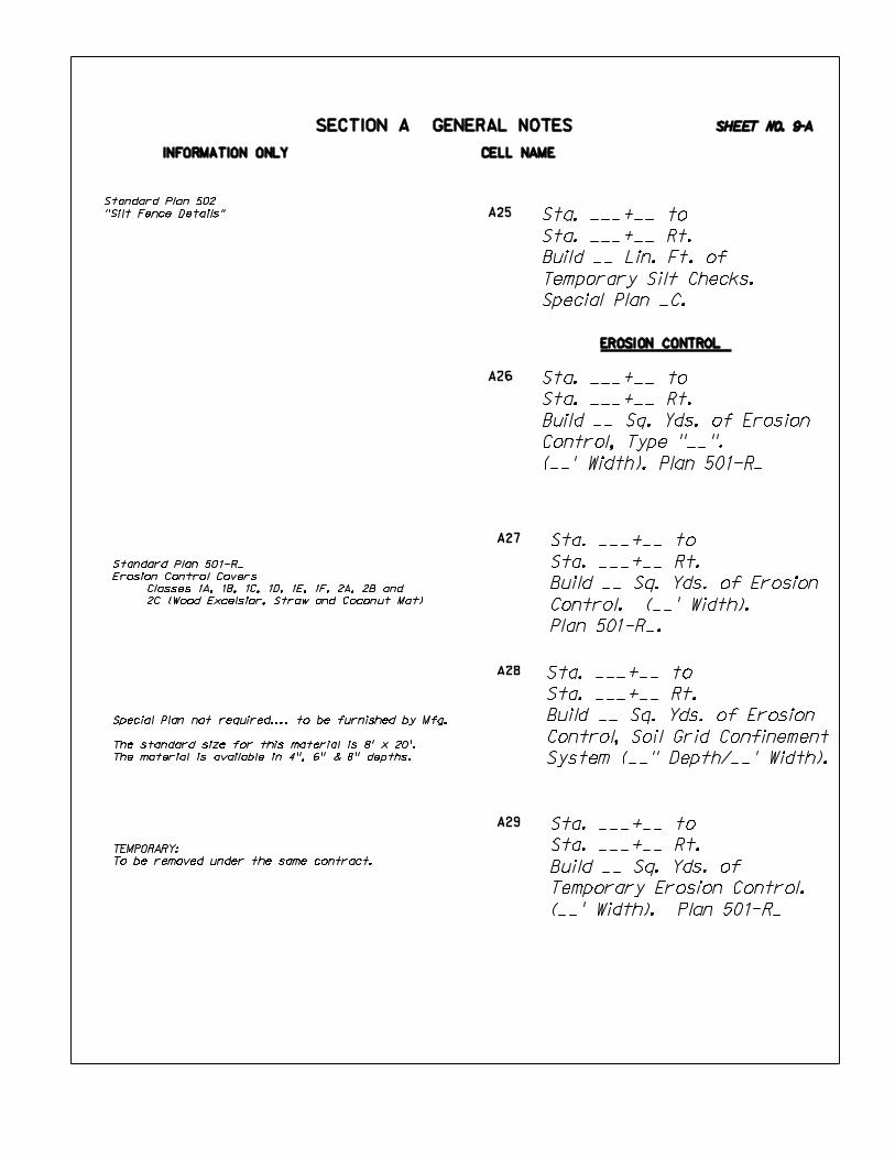
To be removed under the same contract.
Special Plan not required.... to be furnished by Mfg.
The standard size for this material is 8’ x 20’.
The material is available in 4", 6" & 8" depths.
Sta. ___+__ to
Sta. ___+__ Rt.
Build __ Sq. Yds. of
Temporary Erosion Control.
(__’ Width). Plan 501-R_
Sta. ___+__ to
Sta. ___+__ Rt.
Build __ Sq. Yds. of Erosion
Control, Soil Grid Confinement
System (__" Depth/__’ Width).
Sta. ___+__ to
Sta. ___+__ Rt.
Build __ Sq. Yds. of Erosion
Control, Type "__".
(__’ Width). Plan 501-R_
Sta. ___+__ to
Sta. ___+__ Rt.
Build __ Sq. Yds. of Erosion
Control. (__’ Width).
Plan 501-R_.
SHEET NO. 9-A
EROSION CONTROL
Standard Plan 501-R_
Erosion Control Covers
Classes 1A, 1B, 1C, 1D, 1E, 1F, 2A, 2B and
2C (Wood Excelsior, Straw and Coconut Mat)
Standard Plan 502
"Silt Fence Details"

INFORMATION ONLY CELL NAME
SECTION A GENERAL NOTES
Sta. ___+__ Rt.
Build Area Inlet Sediment
Filter.
Detail furnished by Mfg. Contractor.
A30
A31
A32
Sta. ___+__ to
Sta. ___+__ Rt.
Build __ Sq. Yds. of
Slope Protection Netting.
(__’ Width). Plan 501-R_
Sta. ___+__ Rt.
Build Inlet Liner.
See Sketch on Sheet 2-N.
SHEET NO. 10-A
Standard Detail 5480 5
"Inlet Liner Details"
Standard Plan 501-R_
"Erosion Control"
SHEET
SHEET
SHEET
SHEET
SHEET
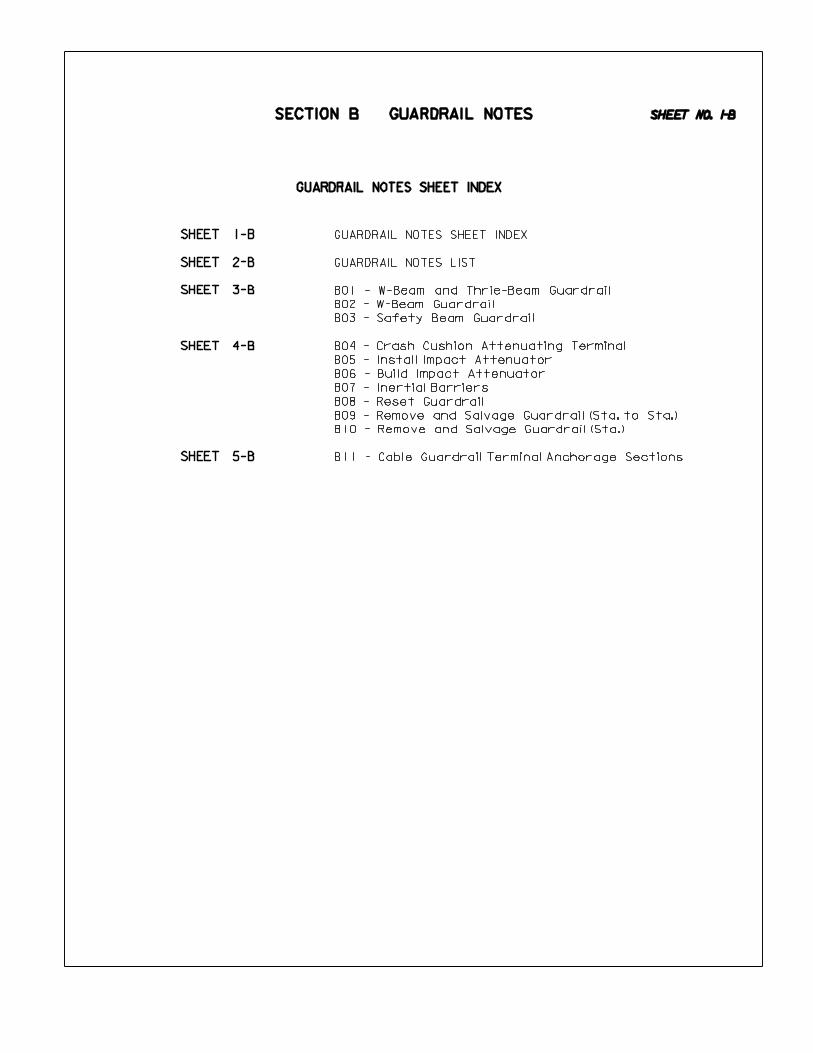
GUARDRAIL NOTES SHEET INDEX
SECTION B GUARDRAIL NOTES
B04 - Crash Cushion Attenuating Terminal
B05 - Install Impact Attenuator
B06 - Build Impact Attenuator
B07 - Inertial Barriers
B08 - Reset Guardrail
B09 - Remove and Salvage Guardrail (Sta. to Sta.)
B10 - Remove and Salvage Guardrail (Sta.)
B11 - Cable Guardrail Terminal Anchorage Sections
B01 - W-Beam and Thrie-Beam Guardrail
B02 - W-Beam Guardrail
B03 - Safety Beam Guardrail
SHEET NO. 1-B
GUARDRAIL NOTES SHEET INDEX
GUARDRAIL NOTES LIST
1-B
2-B
3-B
4-B
5-B

SECTION B GUARDRAIL NOTES
GUARDRAIL NOTES LIST
B01 - W-Beam and Thrie-Beam Guardrail
B02 - W-Beam Guardrail
B03 - Safety Beam Guardrail
B04 - Crash Cushion Attenuating Terminal
B05 - Install Impact Attenuator
B06 - Build Impact Attenuator
B07 - Inertial Barriers
B08 - Reset Guardrail
B09 - Remove and Salvage Guardrail (Sta. to Sta.)
B10 - Remove and Salvage Guardrail (Sta.)
B11 - Cable Guardrail Terminal Anchorage Sections
SHEET NO. 2-B

INFORMATION ONLY CELL NAME
B02
B03
B01Sta. ___+__
Build ___ Lin. Ft. of W-Beam
Guardrail & ___ Lin. Ft. of
Thrie-Beam Guardrail.
Special Plan _C.
SAFETY BEAM GUARDRAIL INFORMATION
Sta. ___+__
Build Safety Beam Guardrail.
_-Bridge Approach Sections.
_-Guardrail End Treatment,
Type I
_-Guardrail End Treatment,
Type II.
Special Plan _C.
SECTION B GUARDRAIL NOTES
End Treatments for W-Beam Guardrail (Paid, 1-Each)
Guardrail End Treatment, Type I - Used for 65 mph and above
for parallel installations or 25:1 Taper Rates. All rectangular
heads on the ends of parallel or 25:1 tapers.
ET-2000 (LET or PLUS) - Extruding Terminal
BEST - Beam Eating Safety Terminal
SKT 350 - Sequential Kinking Terminal
Guardrail End Treatment, Type II - Used for 65 mph and
lower and on 15:1 Taper Rates.
SRT 350 - Curved Slotted Rails
FLEAT - Flared Energy Absorbing Terminal, a tangent
(Rectangular Head, Tapered)
SRT 75 - Three short Slots in the Rail
For more information refer to the Nebraska Department
of Roads’ "Guide to Guardrail Pay Items" document.
Sta. ___+__
Build ____ Lin. Ft. of
W-Beam Guardrail.
_-Bridge Approach Sections.
_-Special Bridge Approach
Section.
_-Guardrail End Treatment,
Type I.
_-Guardrail End Treatment,
Type II.
_-Bullnose End Treatment
(Tapered)
_-Bullnose End Treatment
(Parallel)
_-W-Thrie Beam Transition
Section.
_-End Anchorage Assemblies.
_-Alternate End Anchorage
Assemblies.
_-Culvert Mounted Guardrail
Posts.
_-Concrete Anchor Blocks.
_-Controlled Releasing
Terminal Posts (CRT).
Special Plan _C.
When building a Cable to Safety Beam Guardrail
Transition Section, you do not need a special build
note. This will show up on the Guardrail Installation
Plan.
If you are describing only one corner of a bridge this
note should read Sta. to Sta. (Rt. or Lt.)
Include totals of all Guardrail items in one note for
each bridge. If there is a Guardrail Installation
Special Plan, you do not need (Table ’’*’’) in the
construction note. Tables will be identified on
Guardrail Installation Special Plan. In overpass
situations, use 1-Guardrail note for the stationed
centerline over the bridge and 1-Guardrail note for
the stationed centerline that goes under the bridge to
protect abutments or piers.
When dealing with "Nested Guardrail", include the additional
length in the "Build __ Lin. Ft. of W-Beam Guardrail" note
and let the Guardrail Installation Special Plan show the
details of the "nesting".
REMODEL BRIDGE CURB note should be addressed with the
Bridge note.
If you do not have a Pay Length, the Guardrail note
should be written as note B03.
If CONCRETE ANCHOR BLOCKS are required, they should be
included with the guardrail note.
Installation of Impact Attenuator System
INSTALL - when furnished by the state.
BUILD - when furnished by the contractor.
Inertial Barriers (Fitch Barrels) TEMPORARY
installation by Traffic Engineer.
SHEET NO. 3-B
SAFETY BEAM GUARDRAIL SPECIAL PLANS
Plan Plan Description
Guardrail Location Tables
End Anchorage Assemblies
W-Thrie Beam Transition Section (Paid for as 1-Ea. when separate from B.A.S.)
Special Bridge Approach Section (Thrie-Beam Rail)
M.E.L.T. (Used by permission only) (Not normally used on State highways)
Bridge Approach Section (Includes W-Thrie Beam Transition Section)
Hardware Details (Includes W-Thrie Beam Transition Section)
Design Guide 7774 6 Guardrail End Treatment, Type 1 (ET-2000)
Design Guide 7775 6 Guardrail End Treatment, Type 1 (BEST)
Design Guide 7776 6 Guardrail End Treatment, Type 1 ( SKT-350)
Design Guide 7773 6 Guardrail End Treatment, Type II (SRT-350)
Design Guide 7779 6 Guardrail End Treatment, Type II (FLEAT)
Design Guide 7772 6 Guardrail End Treatment, Type II (SRT-75)
Bull Nose (12.5’ Tapered)
Bull Nose (12.5’ Parallel)
Special Plan 7040 1
Special Plan 7044 1
Special Plan 7041 1
Special Plan 7043 1
Special Plan 7771 1
Special Plan 7075 1
Special Plan 7044 1
Special Plan 7045 1
Special Plan 7071 1

IMPACT ATTENUATORS
INERTIAL BARRIERS
RESETTING CABLE GUARDRAIL ONLY
CRASH CUSHION ATTENUATING TERMINAL
INFORMATION ONLY CELL NAME
B04
B05
B06
B07
B08
B09
Sta. ___+__ to
Sta. ___+__ Lt.
Reset __ Lin. Ft. of
Guardrail. Special Plan _C.
(Includes _-Terminal
Anchorage Sections).
Sta. ___+__
Build Inertial Barriers.
Special Plan _C.
Sta. ___+__
Install _- Crash Cushion
Attenuating Terminal.
Special Plan _C.
Sta. ___+__ to
Sta. ___+__ Lt.
Remove and Salvage _ Lin. Ft.
of Guardrail.
Sta. ___+__
Remove and Salvage _ Lin. Ft.
of Guardrail.
SECTION B GUARDRAIL NOTES
Sta. ___+__
Install _-Impact Attenuators.
Special Plan _C.
Sta. ___+__
Build _-Impact Attenuators.
Special Plan _C.
SYRO-CRASH-CUSHION ATTENUATING TERMINAL
SENTRE-CRASH-CUSHION ATTENUATING TERMINAL
QUADGUARD
TRACC
REACT 350
Fitch Barrels - See Examples in Drafting Room.
The old Standard Plan No. must be blocked
out and made into a Special Plan __C with
the words ’FOR INFORMATION ONLY’ placed
above the title.
Regarding the Standard Plan that was used to
build the existing installation :
Installation of Impact Attenuator System
INSTALL - when furnished by the state.
BUILD - when furnished by the contractor.
Inertial Barriers (Fitch Barrels) TEMPORARY
installation by Traffic Engineer.
Refer to Fitch Barrels as "Inertial Barrier".
"Temporary Inertial Barrier" Does not need a note as
it will be handled on plans from TRAFFIC ENGINEERING.
To reset Guardrail, the stationing includes the End
Sections, if reusing the existing T.A.S.
Guardrail Lengths must be the same to combine in one
note, otherwise you need separate notes.
The Special Plan used to Reset the cable guardrail is
our current Cable Guardrail Plan.
Additional Guardrail Removal Notes are found in the
Removal Note Section:
H13 - Remove Guardrail (Station)
H14 - Remove Guardrail (Station to Station)
H15 - Remove Guard Posts
Two notes are required for Remove and Reset Guardrail:
1-Note to Remove & Salvage Guardrail, and
1-Note to Reset Guardrail.
If you are going to ’Salvage" Guardrail, do so for the
entire installation, not just part of the installation.
"SN25" from the ’std.cel’ cell library:
B10
SHEET NO. 4-B
The existing Cable Guardrail was
constructed in accordance with the
details shown on "For Information
Only Special Plan *C". The Contractor
shall reset the guardrail in accordance
with Standard Plan 702-R_.

INFORMATION ONLY CELL NAME
INTERMEDIATE ANCHORAGE SECTION
SECTION B GUARDRAIL NOTES
Intermediate Anchorage Section is required when pay
length is over 2000 Lin. Ft.
When building Guardrail Sta. to Sta., the length will
not include the Terminal Anchorage Sections.
Sta. ___+__ to
Sta. ___+__ Lt.
Build __ Lin. Ft. of
Cable Guardrail. _-Terminal
Anchorage Sections.
_-Intermediate Anchorage
Section. Special Plan _C.
B11
SHEET NO. 5-B

SHEET
SHEET
SHEET
SHEET
SHEET
SHEET
SHEET
SHEET
SHEET
SHEET
SHEET
1-C1
2-C1
3-C1
4-C1
5-C1
6-C1
7-C1
8-C1
9-C1 PPE24 - Lay Driveway Culvert Pipe & Build Earth Drive
PPE25 - Lay Driveway Culvert Pipe & Build Earth Drive & Surface.
See Sheet 2-S
PPE26 - Build Culvert Pipe for Crossover
PPE27 - Install Twin Culvert Pipe for Temporary Road
PPE28 - Build Twin Culvert Pipe for Temporary Road
PPE29 - Build Culvert Pipe & Extend w/Temp. Culvert Pipe
PPE30 - Build Round Equivalent Storm Sewer Pipe
PPE31 - Build Storm Sewer Pipe
PPE32 - Build Sanitary Sewer Pipe
PPE05 - Build Jacked Culvert Pipe, Type 1 or 2, Class "_"
PPE06 - Build Culvert Pipe as Median Structure
PPE07 - Remove Bridge & Build Culvert Pipe
PPE08 - Build Culvert Pipe w/F.E.S. on Inlet & Outlet in Exist. C.B.C. (Tap)
PPE09 - Build Culvert Pipe w/Headwall & w/Overhang
PPE10 - Build Culvert Pipe w/Headwall & w/Splash Basin
PPE11 - Build Round Equivalent Culvert Pipe w/F.E.S.
PPE12 - Build Round Equivalent Culvert Pipe w/Headwalls
PPE13 - Build Culvert Pipe & Headwalls
PPE14 - Build Twin Culvert Pipe & Headwalls
PPE15 - Build Twin Culvert Pipe w/Flared End Sections
PPE16 - Build Twin Culvert Pipe on Skew & Headwalls
PPE17 - Remove R.C.P. & Build Culvert Pipe w/F.E.S.’s
PPE18 - Build Culvert Pipe w/F.E.S.’s & Bar Grate
PPE19 - Build Culvert Pipe w/F.E.S. on Inlet & Outlet in Stubout
PPE20 - Build Culvert Pipe w/F.E.S.’s and Build Culvert Pipe as Stubout
PPE21 - Build Culvert Pipe for Median Structure w/F.E.S., Bar Grate &
Stubout
PPE22 - Build Culvert Pipe as Irrigation Structure
PPE23 - Build Concrete Flume Type "_" w/Culvert Pipe
PPE01 - Build Culvert Pipe, Type 2, Class "_", Class "_" Bedding (Railroad)
PPE02 - Build Culvert Pipe, Type 2, Jacked (Railroad)
PPE03 - Build Culvert Pipe w/F.E.S.’s
PPE04 - Build Culvert Pipe w/F.E.S. on Inlet & Outlet in Conc. Box Culv.
CULVERT PIPE LEGEND
SHEET NO. 1-C1
PIPE POLICY NOTES LIST
10-C1
11-C1
POLICY NOTES SHEET INDEX
SECTION C1 PIPE POLICY NOTES
PIPE POLICY NOTES SHEET INDEX

PPE01 - Build Culvert Pipe, Type 2, Class "_", Class "_" Bedding
PPE02 - Build Culvert Pipe, Type 2, Jacked
PPE03 - Build Culvert Pipe w/F.E.S.’s
PPE04 - Build Culvert Pipe w/F.E.S. on Inlet & Outlet in Conc. Box Culv.
PPE05 - Build Jacked Culvert Pipe, Type 1 or 2, Class "_"
PPE06 - Build Culvert Pipe as Median Structure
PPE07 - Remove Bridge & Build Culvert Pipe
PPE08 - Build Culvert Pipe w/F.E.S. on Inlet & Outlet in Exist. C.B.C. (Tap)
PPE09 - Build Culvert Pipe w/Headwall & w/Overhang
PPE10 - Build Culvert Pipe w/Headwall & w/Splash Basin
PPE11 - Build Round Equivalent Culvert Pipe w/F.E.S.
PPE12 - Build Round Equivalent Culvert Pipe w/Headwalls
PPE13 - Build Culvert Pipe & Headwalls
PPE14 - Build Twin Culvert Pipe & Headwalls
PPE15 - Build Twin Culvert Pipe w/Flared End Sections
PPE16 - Build Twin Culvert Pipe on Skew & Headwalls
PPE17 - Remove R.C.P. & Build Culvert Pipe w/F.E.S.’s
PPE18 - Build Culvert Pipe w/F.E.S.’s & Bar Grate
PPE19 - Build Culvert Pipe w/F.E.S. on Inlet & Outlet in Stubout
PPE20 - Build Culvert Pipe w/F.E.S.’s and Build Culvert Pipe as Stubout
PPE21 - Build Culvert Pipe for Median Structure w/F.E.S., Bar Grate & Stubout
PPE22 - Build Culvert Pipe as Irrigation Structure
PPE23 - Build Concrete Flume Type "_" w/Culvert Pipe
PPE24 - Lay Driveway Culvert Pipe & Build Earth Drive
PPE25 - Lay Driveway Culvert Pipe & Build Earth Drive & Surface. See Sheet 2-S
PPE26 - Build Culvert Pipe for Crossover
PPE27 - Install Twin Culvert Pipe for Temporary Road
PPE28 - Build Twin Culvert Pipe for Temporary Road
PPE29 - Build Culvert Pipe & Extend w/Temp. Culvert Pipe
PPE23 - Build Round Equivalent Storm Sewer Pipe
PPE31 - Build Storm Sewer Pipe
PPE32 - Build Sanitary Sewer Pipe
SHEET NO. 2-C1
PIPE POLICY NOTES LIST
SECTION C1 PIPE POLICY NOTES

CULVERT PIPE
RAILROAD CULVERT PIPE
INFORMATION ONLY CELL NAME
PPE01
PPE02
PPE03
PPE04
__
__
__
Sta. ___+__
DA=___Ac.,Q =__cfs,HW=__’
Build __" ‘ __’ Culvert Pipe
Type 2, 3, 4, 5, 7 or 8
w/Flared End Section on Inlet
& Outlet in Concrete Box
Culvert, _-__^ Elbow.
Plans 410-R_, 425-R_ &
Special Plan _C. Fill= __’.
Exc.=__ Cu. Yds.
Sta. ___+__
DA=___Ac.,Q =__cfs,HW=__’
Build __’’ ‘ __’ Culvert Pipe
Pipe, Type 2. Class _ ,
Class "_" Bedding w/Flared
End Sections. Plan 410-R_ &
Special Plan _C. Fill= __’.
Exc.=__ Cu. Yds.
Length of Pipe Partially Jacked
Designer should review Design Pipe Material Policy Flow
Chart for Pipe Type and placement restrictions
The Culvert Pipe notes are typical and cover several
situations. Edit out information that does not apply.
NOTE: Q__, D.A. and H.W. required on all crossroad
culvert construction notes.
Q__ - Design Discharge (c.f.s.)
Subscript indicates storm frequency used.
D.A. - Drainage Area in Acres.
H.W. - Design Headwater, depth of flow measured
from the flow line of the inlet.
If drainage information cannot be determined, the
following note should be used:
Design Discharge (Q) and Drainage Area (D.A.) cannot
be determined by office means unless otherwise noted
on the plans.
REQUIRED PIPE LENGTHS UNDER R.R. TRACKS
(Jacking may be required)
< R.R. to end of pipe - 15’ Minor Tracks
< R.R. to end of Pipe - 25’ Major Tracks
Class IV or Class V Pipe may be required in areas of
excessive fill or under R.R. tracks.
Bedding Sketch is required on Culvert X-Sec.
Class IV or Class V Pipe may be required in areas of
excessive fill or under Railroad Tracks
NOTE:
Broken back reference will NOT be made on new pipes.
B.B. - Broken Back
DBL. B.B. - Double Broken Back
A bend on a concrete pipe can be either Vertical or
Horizontal. However, DO NOT specify Horizontal or
Vertical when calling for an elbow or a collar with a bend.
Sta. ___+__
Build __’’ ‘ __’ Culvert Pipe
Type 2, (Includes __’ Jacked
Culvert Pipe, Type 2
Class __).
Special Plans _C & _C.
Fill= __’. Exc.=__ Cu. Yds.
Sta. ___+__
DA=___Ac.,Q =__cfs,HW=__’
Build __" ‘ __’ Culvert Pipe
Type 2, 3, 4, 5, 7 or 8
w/Flared End Sections.
Plan 410-R_ & Special Plan _C.
Fill= __’. Exc.=__ Cu. Yds.
SHEET NO. 3-C1SECTION C1 PIPE POLICY NOTES
BOX CULVERTS with Bends or Breaks:
- Bends are horizontal
- Breaks are vertical.
You DO NOT have to call out the ^ of Bend or Break
on preliminary culvert notes.

CULVERT PIPE
INFORMATION ONLY CELL NAME
PPE05
PPE06
PPE07
PPE08
__
__
Sta. ___+__
Build __’’ ‘ __’ Culvert Pipe
Type 2, 3, 4, 5, 7 or 8 as
Median Structure with Flared
End Sections. Plan 410-R_ &
Special Plan _C. Fill= __’.
Sta. ___+__
DA=__Ac.,Q =__cfs,HW=__’
Build __’’ ‘ __’ Culvert Pipe,
Type 2, 3, 4, 5, 7 or 8 with
Flared End Section on Inlet,
and Outlet in Existing
Conc. Box Culvert. _-Tap,
_-__^ Elbow. Plans 410-R_,
425-R_, 428-R_ &
Special Plan _C. Fill= __’.
Exc.=__ Cu. Yds.
Full Length of Pipe Jacked.
If R.C.P. Class __ is to be Jacked, it must be stated
in the note.
No Excavation Quantity is required for Median
Structures in new embankment.
Structures in existing medians DO require excavation.
If you remove pipe from an ’Existing’ Median Structure,
you need to pay for excavation.
Only pay for a tap if tapping into an existing Inlet,
Culvert or Box Culvert.
Sta. ___+__
Build __’’ ‘ __’ Jacked
Culvert Pipe, Type 1 or 2
Class __. Special Plan _C
Fill= __’. Exc.=__ Cu. Yds.
NOTE:
WHEN USING EXTEND PIPE NOTES, WHEN FILL IS GREATER THAN 10’,
THE NOTE SHOULD INCLUDE:
Fill=__’.
Excavation is not to be paid for when installing new Flared
End Sections directly on existing pipes.
DA=__Ac.,Q =__cfs, HW=__’
Remove & Build __’’ ‘ __’
Culvert Pipe, Type 2, 3, 4, 5,
7 or 8 and Headwalls.
_-__^ Elbow. Plan 425-R_
& Special Plans _C & _C.
Fill= __’. Exc.=__ Cu. Yds.
STA. ___+__
__-__’ SPAN TIMBER BRIDGE
WD. FLOOR, W/__’ CLEAR RDWY.
SHEET NO. 4-C1SECTION C1 PIPE POLICY NOTES

CULVERT PIPE
INFORMATION ONLY CELL NAME
PPE10
PPE11
PPE12
PPE09
__
__
__
__
Sta. ___+__
DA=__Ac.,Q =__cfs, HW=__’
Build __’’ ‘ __’ Round
Equivalent Culvert Pipe,
Type 2, 3, 4 or 5 with Flared
End Sections. Plan 410-R_ &
Special Plan _C. Fill= __’.
Exc.=__ Cu. Yds.
Sta. ___+__
DA=__Ac.,Q =__cfs, HW=__’
Build __’’ ‘ __’ Culvert Pipe,
Type 2, 3, 4, 5, 7 or 8 and
Headwall on Inlet, _-__^
Elbow, with Splash Basin on
Outlet, as Shown by Sketch
on Sheet 2-N. Plan 425-R_ &
Special Plan _C & _C.
Fill= __’. Exc.=__ Cu. Yds.
Sta. ___+__
DA=__Ac.,Q =__cfs, HW=__’
Build __’’ ‘ __’ Culvert Pipe,
Type 2, 3, 4, 5, 7 or 8 and
Headwall on Inlet, with
Overhang on Outlet,Type "_".
Special Plans _C & _C.
Fill= __’. Exc.=__ Cu. Yds.
Sta. ___+__
DA=__Ac.,Q =__cfs, HW=__’
Build __’’ ‘ __’ Round
Equivalent Culvert Pipe, Type
2, 3, 4 or 5 & Headwalls.
Special Plans _C & _C.
Fill= __’. Exc.=__ Cu. Yds.
Designer should review Design Pipe Material Policy Flow
Chart for Pipe Type and placement restrictions
The Round Equivalent notes are typical and cover several
situations. Edit out any Pipe type that does not apply.
Refer to Sheet 3-C2 for Pipe-Arch to Round Equivalent
conversion table and example notes.
If the Headwall Special Plan allows for the construction of
different types of Headwalls, the type must be addressed
in the note.
If you are phasing the construction of a drainage
structure, handle on the drainage cross sections, with
dimensions, stating Phase 1, Phase 2.
DO NOT phase the construction notes in the plans.
Round Equivalent Pipe:
Pipe-Arch: Concrete & Corrugated Metal
Elliptical Pipe: Concrete only
SHEET NO. 5-C1SECTION C1 PIPE POLICY NOTES

CULVERT PIPE
INFORMATION ONLY CELL NAME
PPE13
PPE14
PPE15
PPE16
__
__
__
__
If Headwall Type is required, please note after
the word Headwalls.
Sta. ___+__
DA=__Ac., Q =__cfs, HW=__’
Build __’’ ‘ __’ Culvert Pipe,
Type 2, 3, 4, 5, 7 or 8
and Headwalls.
Special Plans _C & _C.
Fill= __’. Exc.=__ Cu. Yds.
Sta. ___+__
DA=__Ac.,Q =__cfs, HW=__’
Build Twin __’’ ‘ __’ Culvert
Pipe, Type 2, 3, 4, 5, 7 or 8
and Headwalls.
Special Plans _C & _C.
Fill= __’. Exc.=__ Cu. Yds.
Sta. ___+__
DA=__Ac.,Q =__cfs, HW=__’
Build Twin __’’ ‘ __’ Culvert
Pipe, Type 2, 3, 4, 5, 7 or 8
w/Flared End Sections. Plan
410-R_ & Special Plan _C.
Fill= __’. Exc.=__ Cu. Yds.
Sta. ___+__
DA=__Ac.,Q =__cfs, HW=__’
Build Twin __’’ ‘ __’ Culvert
Pipe, Type 2, 3, 4, 5, 7 or 8
on __^ Skew and Headwalls.
Special Plans _C & _C.
Fill= __’. Exc.=__ Cu. Yds.
Multiple Pipes having Flared End Sections require a
sketch showing the dimensions between the pipes
(usually on drainage cross-sections).
WHEN DESCRIBING MULTIPLE PIPES:
Use the ’word’ for the number of pipes,
NOT the number. (i.e. Twin, Triple, etc.)
SHEET NO. 6-C1SECTION C1 PIPE POLICY NOTES

INFORMATION ONLY CELL NAME
PPE17
PPE18
PPE19
__
__
CULVERT PIPE
Sta. ___+__
DA=__Ac.,Q =__cfs, HW=__’
Build ___’’ ‘ __ Culvert Pipe,
Type 2, 3, 4, 5, 7 or 8 with
Flared End Sections & Build
Bar Grate on Inlet. Plans
410-R_, 413-R_ & Special
Plan _C. Fill= __’.
Exc.=__ Cu. Yds.
DA=__Ac.,Q =__cfs, HW=__’
Remove & Build __’’ ‘ __’
Culvert Pipe, Type 2, 3, 4, 5,
7 or 8 with Flared End
Sections. Plan 410-R_ &
Special Plan _C.
Fill= __’. Exc.=__ Cu. Yds.
Sta. ___+__ Lt. to
Sta. ___+__ Lt.
Build __’’ ‘ __’ Culvert Pipe,
Type 2, 3, 4, 5, 7 or 8 with
Flared End Section on
Inlet & Outlet in Stubout,
_-__^ Elbow, _- Concrete
Collar. Plans 410-R_, 425-R_
& Special Plan _C.
Fill= __’. Exc.=__ Cu. Yds.
STA. ___+__
___’’ ‘ __’ REINF. CONC.
PIPE W/HDWLS.
SHEET NO. 7-C1SECTION C1 PIPE POLICY NOTES

CULVERT PIPE FOR FLUMES
CULVERT PIPE
INFORMATION ONLY CELL NAME
PPE20
PPE21
PPE22
PPE23
__
Sta. ___+__
Build __’’ ‘ __’ Culvert Pipe,
Type 2, 3, 4, 5, 7 or 8 for
Median Structure,with Flared
End Section & Build Bar
Grate on Inlet with Outlet in
Stubout, 1-Concrete Collar.
Plans 410-R_, 413-R_, 425-R_.
& Special Plan _C. Fill= __’.
Sta. ___+__ Lt.
Build Concrete Flume, Type __
with ___’’ ‘ __’ Culvert Pipe,
Type 3, 4, 5 or 6.
Special Plans _C & _C.
Sta. ___+__
Build __’’ ‘ __’ Culvert Pipe,
Type 2, 3, 4, 5, 7 or 8
as Irrigation Structure on
__^ Skew w/Siphon Headwalls.
Plan 414 & Special Plan _C.
Fill= __’. Exc.=__ Cu. Yds.
If it is an Irrigation Pipe, it needs to be
stated in the note.
The Culvert Pipe for Flumes need to have
a corrugated interior.
Sta. ____+__
DA=__Ac.,Q =__cfs, HW=__’
Build __’’ ‘ __’ Culvert Pipe,
Type 2, 3, 4, 5, 7 or 8 with
Flared End Sections and
Build __’’ ‘ __’ Culvert Pipe,
Type 2, 3, 4, 5, 7 or 8, as
Stubout. Plan 410-R_ &
Special Plan _C.
Fill= __’. Exc.=__ Cu. Yds.
SHEET NO. 8-C1SECTION C1 PIPE POLICY NOTES

CULVERT PIPE FOR RURAL DRIVE
CULVERT PIPE FOR CROSSOVERS
INFORMATION ONLY CELL NAME
PPE24
Sta. ___+__
Install Twin __’’ ‘ __’
Culvert Pipe, Type 2, 3, 4, 5,
7 or 8. Special Plan _C.
Fill= __’.
Sta. ___+__
Build Twin __’’ ‘ __’
Culvert Pipe, Type 2, 3, 4, 5,
7 or 8. Special Plan _C.
Fill= __’.
Sta. ___+__ to
Sta. ___+__
Build __’’ ‘ _’ Culvert Pipe,
Type 2, 3, 4, 5, 7 or 8.
Special Plan _C. Fill= __’.
If Temporary Culvert Pipe is to be furnished by the
State, use the term ’Install’ rather than ’Build’.
The Designer should check with the District when
specifying type.
If Temporary Culvert Pipe is to be Salvaged and Removed,
the Designer should check with the District for Culvert Type.
Remove Temporary Road with item
Excavation (Established Quantity). Pipe removal is
subsidiary to "Excavation Established Quantity".
DO NOT call for the Temporary Pipes to be removed.
The removal of pipes will be subsidiary to the obliteration
of the Temporary Road. It will be noted in the Spec’s
if it is to be Salvaged.
Show Embankment Quantity required to build
Temporary Road with Earthwork Note.
Use the term ’Install’ if the pipe is to be furnished
by the State.
Use the term ’Build’ if the pipe is to be furnished
by the Contractor.
The Temporary Road < is shown, and labeled on the project
plan & profile sheet. Temporary Road details should NOT
be shown on the mainline plans.
Add this note to the mainline plans:
DNST
STD.CEL
CULVERT PIPE FOR TEMPORARY ROADS
Sta. ___+__ Lt.
Lay __’’ ‘ __’ Driveway
Culvert Pipe, Type 2, 3, 4, 5,
6, 7 or 8 & Build Earth Drive
(__’ Wide) on __% Grade.
Sta. ___+__ Lt.
Lay __’’ ‘ __’ Driveway
Culvert Pipe, Type 2, 3, 4, 5,
6, 7 or 8 & Build Earth
Drive (__’ Wide) on __%
Grade & Surface.
See Sheet 2-S.
"Lay" Driveway Pipes &
"Build" Road/Crossroad Pipes.
Do NOT place build note for Temporary Road surfacing on
plans. Details may be shown on the 2-T Sheet.
Normally a Temporary Road will have it’s own unique <
stationing (i.e. 7000), also it’s own plan & profile sheet
and has a Typical Section drawn on the 2-T Sheets.
PPE25
PPE26
PPE27
PPE28
Place Horizontally on Plan Portion
of Plan & Profile Sheet.
For Details not shown see Temporary
Road Plan & Profile Sheet
SHEET NO. 9-C1SECTION C1 PIPE POLICY NOTES

CULVERT PIPE FOR SEWERS
INFORMATION ONLY CELL NAME
Sta. ___+__
Build ___’’ ‘ __’ Round
Equivalent Storm Sewer Pipe,
Type 1 with Inlet & Outlet in
Curb Inlet. Special Plan _C.
Fill= __’.
Sta. ___+__
Build ___’’ ‘ __’ Storm
Sewer Pipe, Type 1, 7 or 8
with Inlet & Outlet in Curb
Inlet. Special Plan _C.
Fill= __’.
Sta. ___+__
Build __’’ ‘ __’ Sanitary
Sewer Pipe, Type 1, 7 or 8
with Inlet and Outlet in
Junction Box. Fill= __’.
CULVERT PIPE FOR TEMPORARY ROADS
Sta. ___+__
Build ___’’ ‘ __’ Culvert
Pipe, Type 2, 3, 4, 5, 7 or 8,
with Flared End Sections,
Plan 410-R_. Special Plan _C.
Fill= __’. Exc.=__ Cu. Yds.
(Extend with __’ Temp. Culv.
Pipe, Type 2, 3, 4, 5, 7 or 8
on Lt. Special Plan _C.
Fill= __’.)
Pay quantity for new pipe extends to center of new
pipe or M.H., Inlet, etc.
Excavation is subsidiary for Sewers, Junction Boxes,
Catch Basins, Inlets, Retaining Walls & Steps.
Utility Companies can specify the culvert type required.
PPE29
PPE30
PPE31
PPE32
SHEET NO. 10-C1SECTION C1 PIPE POLICY NOTES

TYPE DESCRIPTION
1
2
3
4
5
6
7
8
RCSP
RCP
GCCMP
ACCMP
PCCMP
HDPE-CI
HDPE-SI
PVC
Reinforced Concrete Sewer Pipe
Reinforced Concrete Pipe
High Density Polyethylene (corrugated Interior)
High Density Polyethylene (smooth Interior)
Polyvinyl Chloride Pipe
CULVERT PIPE LEGEND
Galvanized (zinc) Coated Corrugated Metal Pipe
Aluminum Coated Corrugated Metal Pipe
Polymer Coated Corrugated Metal Pipe
CULVERT PIPE LEGEND
CPL
STD.CEL
The Culvert Pipe Legend (CPL) is found in the "STD.CEL" cell library
SHEET NO. 11-C1SECTION C1 PIPE POLICY NOTES

CULVERT NOTES SHEET INDEX
SHEET
SHEET
SHEET
SHEET
SHEET
SHEET
SHEET
SHEET
SHEET
SHEET
SHEET
SHEET
SHEET
SECTION C2 CULVERT NOTES
SHEET
SHEET
1-C2
2-C2
C17 - C.M Pipe - Remove and Install Flared End Sections
C18 - Rd. Equiv. Pipe - Remove Headwall and Extend
C19 - C.M. Pipe w/Hdwls. - Remove Hdwls. & Build F.E.S.
C20 - Build Culvert Pipe & Hdwls.
C21 - Build Twin Culvert Pipe w/F.E.S.
C22 - Build Twin Culvert Pipe on Skew
C23 - Remove R.C.P. and Build Culvert Pipe
C24 - Build Culvert Pipe w/F.E.S’s. & Bar Grate on Inlet
C25 - (Salvage) Remove & Relay C.M. Pipe & Build Conc. Pipe w/F.E.S.’s
C26 - Remove C.M Pipe & Build Conc. Box Culv.
C27 - Conc. Box Culv. - Remove Endwalls & Extend
C28 - Conc. Box Culv. - Remove Endwalls and Extend
C29 - Conc. Box Culv. - Plug Ends and Abandon
C30 - Conc. Box Culv. - Sandfill
C31 - Build Conc. Box Culv.
C32 - Conc. Box Culv. - Remove Endwalls & Extend
C33 - Build Concrete Box Culvert w/C.M.P. Stubout
C34 - Build C.M. Pipe w/Metal F.E.S. on Inlet and Outlet in Stubout
C35 - Build R.C.P. w/Conc. F.E.S.’s & Build R.C.P. Stubout
C36 - Build R.C.P. for Median Structure w/Conc. F.E.S. & Outlet in Stubout
C37 - Build R.C.P. as Irrigation Structure
C38 - Build Steel Irrigation Structure (Permit No.)
C39 - Original Design/Alternate Design Conc. Box Culv.
3-C2
4-C2
5-C2
6-C2
7-C2
8-C2
EXAMPLE NOTES FOR PIPE-ARCH OR ELLIPTICAL PIPES
GENERAL INFORMATION
C01 - Build R.C.P. w/F.E.S.’s
C02 - Build R.C.P. w/F.E.S. on Inlet & Outlet in Conc. Box. Culv.
C03 - R.C.P. - Remove Headwalls, Build Concrete F.E.S.’s
C04 - Build R.C.P. - Class "_" Bedding w/Concrete F.E.S.’s
C13 - Build C.M. Pipe w/Headwall on Inlet & Overhang on Outlet
C14 - Build C.M Pipe w/Headwall on Inlet & Splash Basin on Outlet
C15 - Remove C.M. Pipe w/Drop Inlet
C16 - Build Round Equivalent
C47 - Rd. Equiv. C.M. Pipe-Arch w/Hdwls.
C48 - Rd. Equiv. Culv. Pipe w/F.E.S.
C49 - Rd. Equiv. Culv. Pipe w/Hdwls.
C50 - Rd. Equiv. R.C. Pipe-Arch w/F.E.S.
C51 - Rd. Equiv. R.C. Pipe-Arch w/Hdwls.
C52 - Conc. Box Culv.
PRELIMINARY PIPE NOTES:
C40 - C.M. Pipe w/Hdwls.
C41 - C.M. Pipe w/F.E.S.
C42 - C.M. Pipe w/Drop Inlet
C43 - R.C.P. w/Hdwls.
C44 - R.C.P. w/F.E.S.
C45 - B.B. R.C.P. w/Hdwls.
C46 - Rd. Equiv. C.M. Pipe-Arch w/F.E.S.
C05 - Build R.C.P (Includes Jacked R.C.P.)
C06 - Build Jacked R.C.P.
C07 - Build R.C.P. As Median Structure
C08 - Remove Bridge and Build R.C.P.
C09 - Build Round Equivalent R.C.P.
C10 - Build R.C.P. w/F.E.S. on Inlet & Outlet in Conc. Box Culv.
C11 - Extend R.C.P. & Build Concrete F.E.S.
C12 - C.M. Pipe w/Hdwls. - Remove Headwalls & Extend
SHEET NO. 1-C2
GENERAL NOTES SHEET INDEX
GENERAL NOTES LIST
10-C2
11-C2
12-C2
13-C2
14-C2
15-C2
9-C2

SECTION C2 CULVERT NOTES
CULVERT NOTES LIST
C01 - Build R.C.P. w/F.E.S.’s
C02 - Build R.C.P. w/F.E.S. on Inlet & Outlet in Conc. Box. Culv.
C03 - R.C.P. - Remove Headwalls, Build Concrete F.E.S.’s
C04 - Build R.C.P. - Class "_" Bedding w/Concrete F.E.S.’s
C05 - Build R.C.P (Includes Jacked R.C.P.)
C06 - Build Jacked R.C.P.
C07 - Build R.C.P. As Median Structure
C08 - Remove Bridge and Build R.C.P.
C09 - Build Round Equivalent R.C.P.
C10 - Build R.C.P. w/F.E.S. on Inlet & Outlet in Conc. Box Culv.
C11 - Extend R.C.P. & Build Concrete F.E.S.
C12 - C.M. Pipe w/Hdwls. - Remove Headwalls & Extend
C13 - Build C.M. Pipe w/Headwall on Inlet & Overhang on Outlet
C14 - Build C.M Pipe w/Headwall on Inlet & Splash Basin on Outlet
C15 - Remove C.M. Pipe w/Drop Inlet
C16 - Build Round Equivalent
C17 - C.M Pipe - Remove and Install Flared End Sections
C18 - Rd. Equiv. Pipe - Remove Headwall and Extend
C19 - C.M. Pipe w/Hdwls. - Remove Hdwls. & Build F.E.S.
C20 - Build Culvert Pipe & Hdwls.
C21 - Build Twin Culvert Pipe w/F.E.S.
C22 - Build Twin Culvert Pipe on Skew
C23 - Remove R.C.P. and Build Culvert Pipe
C24 - Build Culvert Pipe w/F.E.S’s. & Bar Grate on Inlet
C25 - (Salvage) Remove & Relay C.M. Pipe & Build Conc. Pipe w/F.E.S.’s
C26 - Remove C.M Pipe & Build Conc. Box Culv.
C27 - Conc. Box Culv. - Remove Endwalls & Extend
C28 - Concrete Box Culvert - Remove Endwalls & Extend
C29 - Conc. Box Culv. - Plug Ends and Abandon
C30 - Conc. Box Culv. - Sandfill
C31 - Build Conc. Box Culv.
C32 - Conc. Box Culv. - Remove Endwalls & Extend
C33 - Build Concrete Box Culvert w/C.M.P. Stubout
C34 - Build C.M. Pipe w/Metal F.E.S. on Inlet and Outlet in Stubout
C35 - Build R.C.P. w/Conc. F.E.S.’s & Build R.C.P. Stubout
C36 - Build R.C.P. for Median Structure w/Conc. F.E.S. & Outlet in Stubout
C37 - Build R.C.P. as Irrigation Structure
C38 - Build Steel Irrigation Structure (Permit No.)
C39 - Original Design/Alternate Design Conc. Box Culv.
C40 - C.M. Pipe w/Hdwls.
C41 - C.M. Pipe w/F.E.S.
C42 - C.M. Pipe w/Drop Inlet
C43 - R.C.P. w/Hdwls.
C44 - R.C.P. w/F.E.S.
C45 - B.B. R.C.P. w/Hdwls.
C46 - Rd. Equiv. C.M. Pipe-Arch w/F.E.S.
C47 - Rd. Equiv. C.M. Pipe-Arch w/Hdwls.
C48 - Rd. Equiv. Culv. Pipe w/F.E.S.
C49 - Rd. Equiv. Culv. Pipe w/Hdwls.
C50 - Rd. Equiv. R.C. Pipe-Arch w/F.E.S.
C51 - Rd. Equiv. R.C. Pipe-Arch w/Hdwls.
C52 - Concrete Box Culvert
SHEET NO. 2-C2

CORRUGATED METAL PIPE
DESIGN PRELIM
Sta. *
Exc.= * Cu. Yds.
CONCRETE PIPE
CULVERT PIPE (OPTIONAL)
Examples of notes for Pipe-Arch or Elliptical Pipes.
Build 48’’ x 72’ Round Equivalent
1 1
2
TABLE
Pipe-Arch Specification Requirements2/3
arch to the lowest portion of the base.
2
1
All dimensions are measured from the inside crests of the corrugations.
þÿ�P�i�p�e�-�A�r�c�h�e�s�-�-�-�2� � � � �
FORMULA: a.) Subtract rise from span. b.) Divide by 2. c.) Add to rise to obtain the equivalent diameter.
C.M. Pipe-Arch Culvert with Metal
Flared End Sections. Plan 410-R_.
Allowable tolerance of + or - 1’’, or 2% of equivalent circular dia., whichever is greater.
SECTION C2 CULVERT NOTES
GENERAL INFORMATION
B Is defined as the vertical dimension from a horiz. line across the widest portion of the
This chart allows you to convert ’’SPAN x RISE’’ to the Round Equivalent dimension
(This applies to the Prelim. as well as the Design Notes)
SHEET NO. 3-C2
17x13
21x15
24x18
28x20
35x24
42x29
49x33
57x38
64x43
71x47
77x52
83x57
Pipe-Arch
Size In.
Equiv.
Dia. In.
15
18
21
24
30
36
42
48
54
60
66
72
17
21
24
28
35
42
49
57
64
71
77
83
13
15
18
20
24
29
33
38
43
47
52
57
Rise
In.
Span
In.
Min. Corner
Radius In.
3
3
3
3
3
þÿ�
4
5
6
7
8
9
Max.
B In.
þÿ�
6
þÿ�
8
þÿ�
þÿ�1
þÿ�1
þÿ�1
15
þÿ�1
18
20
Sta. *
Build 48’’ x 72’ Round Equivalent
Reinf. Concrete Elliptical Pipe with Conc.
Flared End Sections. Plan 410-R_.
Exc.= * Cu. Yds.
Sta. *
Build 48’’ x 72’ Round Equivalent
Reinf. Concrete Pipe-Arch with Conc.
Flared End Sections. Plan 410-R_.
Exc.= * Cu. Yds.
Sta. *
Build 48’’ x 72’ Round Equivalent
Culvert Pipe with Flared End Sections.
Plan 410-R_. Exc.= * Cu. Yds.
STA.*
48’’ x 72’ RD. EQUIV. C.M. PIPE-ARCH
W/F. E. S.
STA.*
48’’ x 72’ RD. EQUIV. REINF. CONC.
ELLIPTICAL PIPE W/F. E. S.
STA.*
48’’ x 72’ RD. EQUIV. REINF. CONC.
PIPE-ARCH W/F. E. S.
STA.*
48’’ x 72’ RD. EQUIV. CULV. PIPE
W/F. E. S.

SECTION C2 CULVERT NOTES
GENERAL INFORMATION
Stationing - Nearest Foot
Length of Pipe - Nearest Foot
Skew Angle - Nearest Degree
Elbows - Nearest Degree
Collar w/_^ Bend - Nearest Degree
Preliminary Notes:
Use Upper and Lower Case letters. Spell out all of the words when possible.
(Exceptions include: Lt., Rt., Conc. Collar, Conn. Band, Cu. Yds., Sq. Yds., Lin. Ft.)
Use all Upper Case letters.
Okay to abbreviate.
STATION
LEFT
RIGHT
CONCRETE
CONNECTING
CORRUGATED METAL
DRIVEWAY
HEADWALLS
FIELD ENTRANCE
FLARED END SECTION(S)
REINFORCED
BROKEN BACK
DOUBLE BROKEN BACK
EQUIVALENT
CULVERT
ROADWAY
BRIDGE
WITH
MANHOLE
STA.
LT.
RT.
CONC.
CONN.
C.M.
DRIVE (PREFERRED) OR DR.
HDWLS.
F.E.
F.E.S.
REINF.
B.B.
DBL. B.B.
EQUIV.
CULV.
RDWY.
BR.
W/
M.H.
SHEET NO. 4-C2
SURVEY/PLAN ACCURACY FOR DRAINAGE PIPES:
PRELIMINARY PIPE NOTE ABBREVIATIONS
ABBREVIATIONWORD
Construction Notes:

CONCRETE PIPE
INFORMATION ONLY CELL NAME
C01
C02
C03
C04
__
__
__
__
SECTION C2 CULVERT NOTES
Sta. ___+__
D.A.=__Ac.,Q =__cfs,H.W.=__’
Build __’’ ‘ __’ Reinforced
Concrete Pipe, Class _,
Class ’’_’’ Bedding w/Concrete
Flared End Sections.
Plan 410-R_.
Exc.=__ Cu. Yds.
Sta. ___+__
D.A.=__Ac.,Q =__cfs,H.W.=__’
Build __" ‘ __’ Reinforced
Concrete Pipe with Concrete
Flared End Sections.
Plan 410-R_.
Exc.=__ Cu. Yds.
D.A.=__Ac.,Q =__cfs,H.W.=__’
Remove Headwalls. Extend
__’ Lt. & __’ Rt. Build
Concrete Flared End Sections.
Plan 410-R_. 2-Conc. Collars
with __^ Bend. Plan 425-R_.
Exc.=__ Cu. Yds.
NOTE: Q__, D.A. and H.W. required on all crossroad
culvert construction notes.
Q__ - Design Discharge (c.f.s.)
Subscript indicates storm frequency used.
D.A. - Drainage Area in Acres.
H.W. - Design Headwater, depth of flow measured
from the flow line of the inlet.
If drainage information cannot be determined, the
following note should be used:
Design Discharge (Q) and Drainage Area (D.A.) cannot
be determined by office means unless otherwise noted
on the plans.
Elbows for a C.M. Pipe do not require Plan 425-R_.
REQUIRED PIPE LENGTHS UNDER R.R. TRACKS
(Jacking may be required)
< R.R. to end of pipe - 15’ Minor Tracks
< R.R. to end of Pipe - 25’ Major Tracks
Class IV or Class V Pipe may be required in areas of
excessive fill or under R.R. tracks.
Bedding Sketch is required on Culvert X-Sec.
Safety Sloped End Sections (Special Plan 4120 1) can be
used in lieu of Flared End Sections.
Sta. ___+__
D.A.=__Ac.,Q =__cfs,H.W.=__’
Build __" ‘ __’ Reinforced
Concrete Pipe with Concrete
Flared End Section on Inlet
& Outlet in Concrete Box
Culvert. Plan 410-R_.
_-__^ Elbow. Plan 425-R_.
Exc.=__ Cu. Yds.
Pay quantity for new pipe, extends to center of
intersecting pipe, M.H. or Inlet, etc.
Always abbreviate Concrete Collars as Conc. Collars.
NEW PIPES - Space dictates whether the note should say
"with" or "w/" Flared End Section(s)
EXTEND PIPE - Note should say "Build" Flared End Section(s)
SHEET NO. 5-C2
STA. ___+__
__" ‘ __’ B.B. REINF. CONC. PIPE
W/HDWLS.
NOTE:
Broken back reference will NOT be made on new pipes.
B.B. - Broken Back
DBL. B.B. - Double Broken Back
A bend on a concrete pipe can be either Vertical or
Horizontal. However, DO NOT specify Horizontal or
Vertical when calling for an elbow or a collar with a bend
on preliminary pipe notes.
NOTE:
DO NOT call out the type of material for Flared
End Sections ANYWHERE on the project.
DO call out the type of pipe on the "Horse Blanket".

INFORMATION ONLY CELL NAME
C06
C07
C08
C09
C05
Sta. ___+__
Build __" ‘ __’ Reinforced
Concrete Pipe as Median
Structure w/Concrete Flared
End Sections. Plan 410-R_.
__
CONCRETE PIPE
Sta. ___+__
Build __" ‘ __’ Jacked
Reinforced Concrete Pipe,
Class __. Exc.=__ Cu. Yds.
SECTION C2 CULVERT NOTES
Sta. ___+__
D.A.=__Ac.,Q =__cfs,H.W.=__’
Build __" ‘ __’ Round
Equivalent Reinforced Conc.
Pipe and Headwalls. Special
Plan _C. Exc.=__ Cu. Yds.
Sta. ___+__
Build __’’ ‘ __’ Reinforced
Concrete Pipe (Includes __’
Jacked R.C.P. Class __).
Exc.=__ Cu. Yds.
Length of Pipe Partially Jacked.
Class IV or Class V Pipe may be required in areas of
excessive fill or under Railroad Tracks.
Full Length of Pipe Jacked.
If R.C.P. Class __ is to be Jacked, it must be stated
in the note.
No Excavation Quantity is required for Median Structures
in new embankment.
If you remove pipe from an ’Existing’ Median Structure
you need to pay for excavation.
Excavation & Concrete Collars are NOT to be paid
for when only installing new Flared End Sections directly
on existing pipes.
If a Headwall Type is required, please note after the
word Headwalls.
__
STA. ___+__
_-____’ SPAN TIMBER BR. WD.
FLOOR, W/___’ CLEAR RDWY.
D.A.=__Ac.,Q =__cfs,H.W.=__’
Remove & Build __" ‘ __’
Reinforced Concrete Pipe &
Headwalls. Special Plan _C.
_-__^ Elbow. Plan 425-R_.
Exc.=__ Cu. Yds.
SHEET NO. 6-C2
CORRUGATED METAL PIPE
CONCRETE PIPE
INFORMATION ONLY CELL NAME
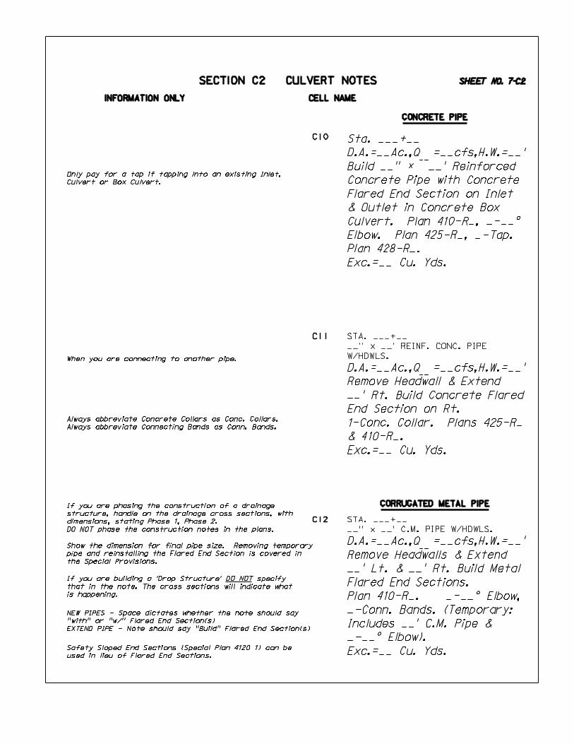
C10
C11
C12
__
__
__
SECTION C2 CULVERT NOTES
Sta. ___+__
D.A.=__Ac.,Q =__cfs,H.W.=__’
Build __" ‘ __’ Reinforced
Concrete Pipe with Concrete
Flared End Section on Inlet
& Outlet in Concrete Box
Culvert. Plan 410-R_, _-__^
Elbow. Plan 425-R_, _-Tap.
Plan 428-R_.
Exc.=__ Cu. Yds.
D.A.=__Ac.,Q =__cfs,H.W.=__’
Remove Headwall & Extend
__’ Rt. Build Concrete Flared
End Section on Rt.
1-Conc. Collar. Plans 425-R_
& 410-R_.
Exc.=__ Cu. Yds.
D.A.=__Ac.,Q =__cfs,H.W.=__’
Remove Headwalls & Extend
__’ Lt. & __’ Rt. Build Metal
Flared End Sections.
Plan 410-R_. _-__^ Elbow,
_-Conn. Bands. (Temporary:
Includes __’ C.M. Pipe &
_-__^ Elbow).
Exc.=__ Cu. Yds.
When you are connecting to another pipe.
Only pay for a tap if tapping into an existing Inlet,
Culvert or Box Culvert.
Show the dimension for final pipe size. Removing temporary
pipe and reinstalling the Flared End Section is covered in
the Special Provisions.
If you are building a ’Drop Structure’ DO NOT specify
that in the note. The cross sections will indicate what
is happening.
Safety Sloped End Sections (Special Plan 4120 1) can be
used in lieu of Flared End Sections.
If you are phasing the construction of a drainage
structure, handle on the drainage cross sections, with
dimensions, stating Phase 1, Phase 2.
DO NOT phase the construction notes in the plans.
Always abbreviate Concrete Collars as Conc. Collars.
Always abbreviate Connecting Bands as Conn. Bands.
NEW PIPES - Space dictates whether the note should say
"with" or "w/" Flared End Section(s)
EXTEND PIPE - Note should say "Build" Flared End Section(s)
SHEET NO. 7-C2
STA. ___+__
__’’ x __’ REINF. CONC. PIPE
W/HDWLS.
STA. ___+__
__’’ x __’ C.M. PIPE W/HDWLS.

INFORMATION ONLY CELL NAME
C13
C14
C15
C16
__
__
__
CORRUGATED METAL PIPE
SECTION C2 CULVERT NOTES
Remove.
Sta. ___+__
D.A.=__Ac.,Q =__cfs,HW..=__’
Build __" ‘ ___’ Round
Equivalent Corrugated Metal
Pipe-Arch Culvert &
Headwalls. Special Plan _C.
Exc.=__ Cu. Yds.
Sta. ___+__
D.A.=__Ac.,Q =__cfs,H.W.=__’
Build __" ‘ __’ Corrugated
Metal Pipe with Headwall on
Inlet & Overhang on Outlet.
Special Plan _C.
Exc.=__ Cu. Yds.
Sta. ___+__
D.A.=__Ac.,Q =__cfs,H.W.=__’
Build __" ‘ __’ Corrugated
Metal Pipe with Headwall on
Inlet. Special Plan _C.
_-__^ Elbow & Splash Basin
on Outlet, as Shown by
Sketch on Sheet 2-N.
Exc.=__ Cu. Yds.
SHEET NO. 8-C2
STA. ___+__
__" ‘ __’ C.M. PIPE W/DROP
INLET.

OPTIONAL PIPE
INFORMATION ONLY CELL NAME
C17
C18
__
Sta. ___+__
D.A.=__Ac.,Q =__cfs,H.W.=__’
Build Twin __" ‘ __’ Culvert
Pipe w/Flared End Sections.
Plan 410-R_.
Exc.=__ Cu.Yds.
__
CORRUGATED METAL PIPE
SECTION C2 CULVERT NOTES
Remove Headwalls & Extend
__’ Lt. & __’ Rt. Build Metal
Flared End Sections.
Plan 410-R_. _-Conn. Bands.
Exc.=__ Cu. Yds.
Sta. ___+__
D.A.=__Ac.,Q =__cfs,H.W.=__’
Build __" ‘ __’ Culvert Pipe
& Headwalls. Special Plan _C.
Exc.=__ Cu. Yds.
Remove Headwalls & Extend
__’ Lt. & __’ Rt. Build Metal
Flared End Sections.
Plan 410-R_. _-Conc. Collars.
Plan 425-R_.
Exc.=__ Cu. Yds.
Remove Flared End Sections &
Extend __’ Lt. & __’ Rt.
Reinstall Flared End Sections.
_-Conn. Bands.
Exc.=__ Cu. Yds.
DO NOT remove 2 ft. of pipe unless the existing
pipe end is mitered.
If the Headwall Special Plan allows for the construction
of different types of Headwalls, the type must be
addressed in the note.
Multiple Pipes having Flared End Sections require a
sketch showing the dimensions between the pipes.
(Usually on drainage cross-sections).
Safety Sloped End Sections (Special Plan 4120 1) can be
used in lieu of Flared End Sections.
DO NOT specify the type of material when
"Reinstalling" a Flared End Section.
If extending Rd. Equiv. pipe, call for Special Conc.
Collars, regardless of pipe material.
C19
C20
C21
SHEET NO. 9-C2
STA. ___+__
__’’ ‘ ___’ RD. EQUIV. C.M. PIPE-
ARCH W/HDWLS.
STA. ___+__
__’’ ‘ ___’ C.M. PIPE W/F.E.S.
STA. ___+__
__’’ ‘ ___’ C.M. PIPE W/HDWLS.

INFORMATION ONLY CELL NAME
__
__
__
__
OPTIONAL PIPE
SECTION C2 CULVERT NOTES
Sta. ___+__
D.A.=__Ac.,Q =__cfs,H.w.=__’
Build Twin __" ‘ __’ Culvert
Pipe on __^ Skew &
Headwalls. Special Plan _C.
Exc.=__ Cu. Yds.
D.A.=__Ac.,Q =__Cfs,H.W.=__’
Remove & Build __" ‘ __’
Culvert Pipe with Flared End
Sections. Plan 410-R_.
Exc.=__ Cu. Yds.
Sta. ___+__
D.A.=__Ac.,Q =__cfs,H.W.=__’
Build __" ‘ __’ Culvert Pipe
with Flared End Sections
& Build Bar Grate on Inlet.
Plan 410-R_ & 413-R_.
Exc.=__ Cu. Yds.
D.A.=__Ac.,Q =__cfs,H.W.=__’
(Salvage). Remove & Relay at
Sta. ___+__.
Build __" ‘ ___’ Concrete
Pipe with Flared End Sections.
Plan 410-R_.
Exc.=__ Cu.Yds
Safety Sloped End Sections (Special Plan 4120 1) can be
used in lieu of Flared End Sections.
WHEN DESCRIBING MULTIPLE PIPES:
Use the ’word’ for the number of pipes,
NOT the number. (i.e. Twin, Triple, etc.)
If a ROADWAY PIPE is going to be removed and reused, or
sent to the Maintenance Yard for future use, we should
call for (Salvage) in the note.
If pipe is to be reused at a new location, the note should
state ’’Relay __’’x __’ Pipe from Sta. __+__.’’
You DO NOT need to specify (Salvage) for DRIVEWAY PIPES,
even if pipe is to be kept.
Standard Plan 413-R_ (Bar Grate for Flared End Sections)
is located in the Standard/Special Plan Book.
C22
C23
C24
C25
SHEET NO. 10-C2
STA. ___+__
__’’ ‘ ___’ REINF. CONC. PIPE
W/HDWLS.
STA. ___+__ LT.
__’’ ‘ ___’ C.M. PIPE

INFORMATION ONLY CELL NAME
__
Plug Ends & Abandon.
Plan 428-R_.
__
CONCRETE BOX CULVERTS
Remove Endwalls.
Sandfill __Cu. Yds.
Plug Ends and Abandon.
Plan 428-R_.
SECTION C2 CULVERT NOTES
D.A.=__Ac.,Q =__cfs,H.W.=__’
Remove Endwalls & __’ of
Barrel. Extend __’ Lt.
_-__^ Bend. Plans ___ &
403-R_. Fill=__’.
Exc.=__ Cu. Yds.
D.A.=__Ac.,Q =__cfs,H.W.=__’
Remove Endwalls & __’ of
Barrel. Extend __’ Lt. &
__’ Rt. _-__^ Bend.
Plans ___ & 403-R_.
Fill=__’. Exc.=__ Cu. Yds.
A Box culvert will need a structure number when the
span exceeds 20’.
SURVEY/PLAN ACCURACY FOR DRAINAGE BOX CULVERTS:
Stationing - Nearest Foot
Height & Width of Box - As Surveyed
Length of Box - As Surveyed
Skew Angle - Nearest Degree
Sandfill note example:
Note C29:
If the size of the Barrel(s) is not covered in the chart
that is located on Standard Plan 428-R_, you will need to
have a Special Plan made up by the Bridge Dept.
Plug Ends & Sandfill.
NO SANDFILL
SANDFILL
If only removing Endwalls & 2’ of Barrel on one side,
the note should read:
"Remove Endwalls on Rt. (or Lt.) & 2’ of Barrel."
Note C30:
If a Sandfill Sketch is to be shown on the Drainage
X-Sections, label subsidiary. You do not need to refer
to the Sketch in the note.
If there is not room for the Sandfill Sketch on the
drainage X-Sections, the sketch may be placed on the 2-N
Sheet, but it must be noted ’See Sketch on Sheet 2-N’.
If a Box Culvert requires a Conrete Apron, you do not need
to call it out in the Construction Note. The Special Plan
will show how the Box Culvert is to be built.
When removing these walls, use the term "Endwalls".
Example:
"Remove Endwalls & 2’ of Barrel."
The term ENDWALLS in this case applies to straight wall,
wingwalls and the parapet.
(All walls at the end of the Box Culvert)
When describing a Box Culvert in the Preliminary Pipe Note,
ALWAYS use the term "Wingwalls" regardless if the wingwalls
are straight or flared.
Keep in mind that not all Box Culverts have wingwalls. Some
are just Box Culverts.
A Box Culvert will NEVER have Headwalls. Likewise a
Culvert Pipe will NEVER have Wingwalls.
__
STA. ___+__
__’’ ‘ ___’ C.M. PIPE W/HDWLS.
D.A.=__Ac.,Q =__cfs,H.W.=__’
Remove. Build __’ ‘ __’
‘ ___’ Concrete Box Culvert
on __^ Skew. Plan __.
__- Control Joints.
Plan 404-R_. Fill=__’.
Exc.=__ Cu. Yds.
C26
C27
C28
C29
C30
SHEET NO. 11-C2
STA. ___+__ #(S______)
TWIN __’ ‘ __’ ‘ ___’ CONC. BOX
CULV. ON __^ SKEW W/WINGWALLS.
STA. ___+__ #(S_______)
TWIN __’ ‘ __’ ‘ ___’ CONC. BOX
CULV. ON __^ SKEW W/WINGWALLS.
STA. ___+__ #(S_______)
__’ ‘ __’ ‘ ___’ CONC. BOX CULV.
STA. ___+__ #(S_______)
__’ ‘ __’ ‘ ____’ CONC. BOX CULV.
BOX CULVERTS with Bends or Breaks:
- Bends are horizontal
- Breaks are vertical.
You DO NOT have to call out the ^ of Bend or Break
on preliminary culvert notes.

INFORMATION ONLY CELL NAME
__
__
__
CONCRETE BOX CULVERTS
STUBOUT PIPES
Sta. ___+__
D.A.=__Ac.,Q =__cfs,H.W.=__’
Build __’ ‘ __’ ‘ __’
Concrete Box Culvert with
__" ‘ __’ Corrugated Metal
Pipe Stubout. Plan ___.
Fill=__’. Exc.=__ Cu. Yds.
SECTION C2 CULVERT NOTES
Sta. ___+__
D.A.=__Ac.,Q =__cfs,H.W.=__’
Build __’ ‘ __’ ‘ __’
Concrete Box Culvert.
Plan ___. Fill=__’.
Exc.=__ Cu. Yds.
D.A.=__Ac.,Q =__cfs,H.W.=__’
Remove Endwalls & __’ of
Barrel. Extend __’ Lt. &
__’ Rt. Plan ___ &
Special Plan _C. Fill= __’.
Exc.=__ Cu. Yds.
Sta. ___+__ Lt. to
Sta. ___+__ Lt.
Build __" ‘ ___’ Corrugated
Metal Pipe with Metal Flared
End Section on Inlet & Outlet
in Stubout. Plan 410-R_.
_-__^ Elbow. _-Conn. Bands.
Exc.=__ Cu. Yds.
This note should be boxed & leadered.
This note should NOT be boxed & leadered.
If you do NOT remove the endwalls, but will be doweling
the Highway structure to the Railroad structure.
Remove Endwalls.
Example of a Railroad Structure to a Roadway Structure:
Make no deduction for concrete in Box Culverts
where stubouts are built.
Endwall Removed
Endwall Intact
C31
C32
C33
C34
SHEET NO. 12-C2
STA. ___+__ #(S_______)
__’ ‘ __’ ‘ ___’ CONC. BOX CULV.
STA. ___+__: _’ LT.
__’ ‘ __’ ‘ ___’ CONC. RR BOX CULV.
W/ENDWALLS.
STA. ___+__: _’ LT.
__’ ‘ __’ ‘ ___’ CONC. RR BOX CULV.
W/ENDWALLS.

INFORMATION ONLY CELL NAME
__
Sta. ___+__
Build __" ‘ ___’ Reinforced
Concrete Pipe for Median
Structure w/Conc. Flared End
Section & Build Bar Grate on
Inlet. Outlet in Stubout.
Plan 410-R_ & 413-R_.
STUBOUT PIPES
MISCELLANEOUS STRUCTURES
SECTION C2 CULVERT NOTES
Sta. ___+__ (Permit No. __)
Build __" ‘ __’ Steel
Irrigation Structure with
__" ‘ __’ Steel Casting.
_-__^ Elbow & _-Coupling
Connectors.
Exc.=__ Cu. Yds.
Sta. ___+__
D.A.=__Ac.,Q =__cfs,H.W.=__’
Build __’’ ‘ __’ Reinforced
Concrete Pipe with Concrete
Flared End Sections.
Plan 410-R_ & Build __" ‘ __’
Reinforced Concrete Pipe
Stubout. Exc.=__ Cu. Yds.
Sta. ___+__
Build __" ‘ __’ Reinforced
Concrete Pipe as Irrigation
Structure on __^ Skew
w/Siphon Headwalls. Plan 414
& Special Plan __C.
Exc.=__ Cu. Yds.
If it is an Irrigation Pipe it needs to be
stated in the note.
(Permit No. __) Refer to permit issued by
Maintenance Division.
C35
C36
C37
C38
SHEET NO. 13-C2
INFORMATION ONLY CELL NAME
__
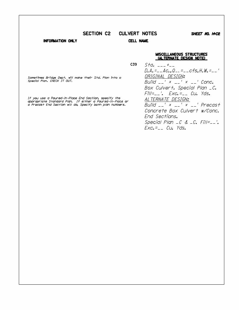
SECTION C2 CULVERT NOTES
Sta. ___+__
D.A.=__Ac.,Q =__cfs,H.W.=__’
ORIGINAL DESIGN:
Build __’ ‘ __’ ‘ __’ Conc.
Box Culvert. Special Plan _C.
Fill=__’. Exc.=__ Cu. Yds.
ALTERNATE DESIGN:
Build __’ ‘ __’ ‘ __’ Precast
Concrete Box Culvert w/Conc.
End Sections.
Special Plan _C & _C. Fill=__’.
Exc.=__ Cu. Yds.
Sometimes Bridge Dept. will make their Std. Plan into a
Special Plan. CHECK IT OUT.
If you use a Poured-in-Place End Section, specify the
appropriate Standard Plan. If either a Poured-in-Place or
a Precast End Section will do, Specify both plan numbers.
C39
SHEET NO. 14-C2
MISCELLANEOUS STRUCTURES
(ALTERNATE DESIGN NOTE)

INFORMATION ONLY CELL NAME
SECTION C2 CULVERT NOTES
C40
C41
C42
C43
C45
C46
C47
C48
C49
C50
C51
C52
Examples of PRELIMINARY PIPE NOTES
(See Section "J" for Existing Bridge note examples)
Preliminary Pipe Notes use all Capital letters.
CO = 4
WT = 1
TX = 10 (100 scale)
These Preliminary Pipe Note Cells are starting points for
the notes. They may need to be modified to fit the
actual situation. The following are some examples of
modified notes:
STA. 123+45
24" ‘ 60’ REINF. CONC. PIPE
W/INLET IN CURB INLET &
HDWL. ON OUTLET
STA. 123+45
24" ‘ 60’ REINF. CONC. PIPE
W/INLET & OULET IN CURB INLET
STA. 123+45
24" ‘ 60’ REINF. CONC. PIPE
W/INLET IN CURB INLET &
F.E.S. ON OUTLET
STA. 123+45
24" ‘ 60’ REINF. CONC. PIPE
W/INLET IN CURB INLET &
OUTLET IN MANHOLE
STA. 123+45
24" ‘ 60’ REINF. CONC. PIPE
W/INLET & OUTLET IN MANHOLE
STA. 123+45
24" ‘ 60’ REINF. CONC. PIPE
W/HDWL. ON INLET &
F.E.S. ON OUTLET
When describing a pipe under a driveway, we need to
say that it is a "DR. PIPE".
If we know the type of material, we need to say it in the
note. (i.e. C.M. DR. PIPE or CONC. DR. PIPE)
If the material is unknown, the note should say "DR. PIPE".
Refer to note cell E02 or E05 for a "C.M. DR. PIPE".
C44
See Sheet No. 4-C2 for Preliminary Pipe Note abbreviations.
STA. ___+__
__" ‘ __’ REINF. CONC. PIPE
W/F.E.S.
STA. ___+__
__" ‘ __’ C.M. PIPE W/DROP INLET
STA. ___+__
__" ‘ __’ C.M. PIPE W/HDWLS.
STA. ___+__
__" ‘ __’ C.M. PIPE W/F.E.S.
STA. ___+__
__" ‘ __’ REINF. CONC. PIPE
W/HDWLS.
STA. ___+__
__" ‘ __’ B.B. REINF. CONC. PIPE
W/HDWLS.
STA. ___+__
__" ‘ __’ RD. EQUIV. C.M. PIPE-
ARCH W/F.E.S.
STA. ___+__
__" ‘ __’ RD. EQUIV. C.M. PIPE-
ARCH W/HDWLS.
STA. ___+__
__" ‘ __’ RD. EQUIV. CULV. PIPE
W/F.E.S.
STA. ___+__
__" ‘ __’ RD. EQUIV. CULV. PIPE
W/HDWLS.
STA. ___+__
__" ‘ __’ RD. EQUIV. REINF.
CONC. PIPE-ARCH W/F.E.S.
STA. ___+__
__" ‘ __’ RD. EQUIV. REINF.
CONC. PIPE-ARCH W/HDWLS.
STA. __+__
__’ ‘ __’ ‘ ___’ CONC. BOX CULV.
SHEET NO. 15-C2
If a pipe is a B.B. (Broken Back) or a DBL. B.B. (Double
Broken Back), you DO NOT have to call out the ^ of Elbow(s)
on preliminary pipe notes.

CONCRETE NOTES SHEET INDEX
SHEET
SHEET
SHEET
SHEET
SHEET
SHEET
SECTION D CONCRETE NOTES
D08 - Build Concrete Terrace Steps
D09 - Build Reinforced Concrete Steps
D10 - Build Concrete Retaining Wall
D11 - Build MSE Wall
D12 - Build Concrete Ditch Lining
D13 - Build Concrete Island Nose
D14 - Remove Pavement and Build Concrete Island Nose
D15 - Build Concrete Median Surfacing
D16 - Remove and Build Concrete Sidewalk
D17 - Build Curb Ramp
D18 - Build Concrete Curb, Type "_"
D19 - Build Concrete Median Curb
D20 - Build Concrete Barrier Curb
D21 - Build Combination Concrete Curb and Gutter
D22 - Build Concrete Base Course
D23 - Build Concrete Pavement Repair
D24 - Build Asphalt Patching of Concrete Pavement
D25 - Build Pavement Repair
D26 - Build Concrete Pavement
D27 - Build Dowelled Concrete Pavement
CONCRETE NOTES LIST
D01 - Build Pavement Approach Slab Type"_"
D02 - Build Pavement Approach Slab
D03 - Build Concrete Flume Type "_"
D04 - Build Concrete Flume Type "_" w/C.M.P.
D05 - Remove and Build Concrete Drive
D06 - Build Concrete Drive
D07 - Drop Curb for Driveway
CONCRETE NOTES SHEET INDEX
SHEET NO. 1-D
1-D
2-D
3-D
4-D
5-D
6-D

SECTION D
CONCRETE NOTES LIST
SECTION D CONCRETE NOTES
D01 - Build Pavement Approach Slab Type"_"
D02 - Build Pavement Approach Slab
D03 - Build Concrete Flume Type "_"
D04 - Build Concrete Flume Type "_" w/C.M.P.
D05 - Remove and Build Concrete Drive
D06 - Build Concrete Drive
D07 - Drop Curb for Driveway
D08 - Build Concrete Terrace Steps
D09 - Build Reinforced Concrete Steps
D10 - Build Concrete Retaining Wall
D11 - Build MSE Wall
D12 - Build Concrete Ditch Lining
D13 - Build Concrete Island Nose
D14 - Remove Pavement and Build Concrete Island Nose
D15 - Build Concrete Median Surfacing
D16 - Remove and Build Concrete Sidewalk
D17 - Build Curb Ramp
D18 - Build Concrete Curb, Type "_"
D19 - Build Concrete Median Curb
D20 - Build Concrete Barrier Curb
D21 - Build Combination Concrete Curb and Gutter
D22 - Build Concrete Base Course
D23 - Build Concrete Pavement Repair
D24 - Build Asphalt Patching of Concrete Pavement
D25 - Build Pavement Repair
D26 - Build Concrete Pavement
D27 - Build Dowelled Concrete Pavement
SHEET NO. 2-D

INFORMATION ONLY CELL NAME
D01
D03
D04
D05
D02
D06
D07
Sta. ___+__ to
Sta. ___+__
Build Pavement Approach Slab.
Special Plan _C.
SECTION D CONCRETE NOTES
Sta. ___+__ Lt.
Build Concrete Flume, Type _
w/__" ‘ ___’ Corrugated
Metal Pipe. Special Plan _C.
Note D05 use for Urban Drives only
One note needed at each end of Bridge (or as required).
One note cannot cover both slabs.
The Bridge Approach Slabs may be part of the bridge plan,
however you still need the Pavement Approach Slab note
for each end of the bridge.
Special Plan or Special Plan C to match Bridge
Naming conventions.
FLUME TYPE
I
II
IV
V
VI
VII
VIII
SPECIAL PLAN NUMBER
4341-1
4342-1
4344-1
4345-1
4346-1
4347-1
4348-1
For Urban jobs show normal driveway geometrics on plans.
There are 7-Types of Flume Special Plans that are approved.
Flume Types IV, V, VI, VII & VIII are 2-sheet plans.
The second sheet is similar to an Area Inlet. Although Flume
Types IV, V, VII & VIII show Elbows on the Special Plan, they
are not called for in the construction note. They should be
shown in Comp’s. and also on Cross Sections, if applicable.
(FLUME TYPE III HAS BEEN VOIDED)
Sta. ___+__ Lt.
Build Concrete Flume, Type _.
L=__’. Special Plan _C.
Note D07 is used at driveway locations when building
Combination Curb & Gutter in front of the driveway.
Stationing for Combination Concrete Curb & Gutter can
continue through driveway locations.
Sta. ___+__ to
Sta. ___+__
Build Pavement Approach Slab
Type __, (__’ Wide).
Special Plan _C.
The note may call out for a type of Bridge Approach
Section if more than one type is detailed on the plan.
Sta. ___+__ Lt.
Remove __ Sq. Yds. of
Driveway & Build __ Sq. Yds.
of Concrete Drive.
Plan 301-R_.
Sta. ___+__ Lt.
Build __ Sq. Yds. of
Concrete Drive. Plan 301-R_.
Sta. ___+__ to
Sta. ___+__ Lt.
Drop Curb for Driveway.
Plan 301-R_.
SHEET NO. 3-D
For reference only.

INFORMATION ONLY CELL NAME
D09
D10
D08Sta. ___+__ Lt.
Build __’ Concrete Terrace
Steps. __-Risers, __ Lin. Ft.
of Handrail. Special Plan _C.
Sta. ___+__ to
Sta.___+__
Build __ Lin. Ft. of
__’ Concrete Retaining Wall,
__ Surface. __-Entrance
Corners and __-Wall Corners.
Special Plan _C.
Sta. ___+__ Lt.
Build Reinforced Concrete
Steps. __’ Wall, __-Risers,
__ Lin. Ft. of Handrail.
Special Plan _C.
Sta. ___+__
Build __ Lin. Ft. of Concrete
Ditch Lining with Type ’’__’’
Inlet. Plan 455.
Sta. ___+__ to
Sta.___+__ Rt.
Build MSE Wall.
Special Plan _C.
SECTION D CONCRETE NOTES
Remove ’Ditch Liner’ by Sq. Yds.
Build ’Ditch Lining’ by Lin. Ft.
Nose integral and subsidiary with Concrete Pavement.
Excavation Subsidiary. Obtain plan from Bridge Dept.
Obtain plan from Bridge Dept.
(*) Define Level or Surcharge Surface.
Excavation is Subsidiary.
Obtain plan from See Bridge Dept.
Sta. ___+__ to
Sta. ___+__
Build __’ Concrete Island
Nose. Plan 301-R_.
Sta. ___+__ to
Sta. ___+__
Remove __ Sq. Yds. of
Pavement & Build Concrete
Island Nose. Plan 301-R_.
D11
D12
D13
D14
SHEET NO. 4-D

INFORMATION ONLY CELL NAME
Sta. ___+__ Rt.
Build Curb Ramp, Type __.
Special Plan _C.
SECTION D CONCRETE NOTES
Do not specify type of material when removing walk.
State the width of the New Sidewalk in the note.
When new Conc. Pavement is placed adjacent to
existing concrete, it is necessary to install Tie Bars.
It is NOT necessary to show the Tie Bars in
plan view. (Sheet 2-T is sufficient).
DO NOT place ’INSTALL TIE BAR’ note on the plans.
But, you DO have to submit a Tie Bar summary of
quantities for the 2-S Sheet.
COMBINATION CONCRETE CURB & GUTTER
Min. width = 2’-0’’, Max. width = 3’-6’’
NO joints. . . NO steel. . . NO subgrade Prep.
Curb Ramps are subsidiary to ’SIDEWALK CONSTRUCTION’
Curb Ramp Areas (Sq. Yds.) included in Sidewalk quantity.
Sta. ___+__ to
Sta. ___+__
Build __ Sq. Yds. of
Concrete Median Surfacing.
Plan 301-R_.
Sta. ___+__ to
Sta. ___+__ Lt.
Remove __ Sq. Yds. of Walk &
Build __ Sq. Yds. of __’
Concrete Sidewalk.
Plan 301-R_.
Sta. ___+__ to
Sta. ___+__
Build __ Lin. Ft. of Concrete
Curb, Type __. Plan 301-R_.
Sta. ___+__ to
Sta. ___+__
Build __ Lin. Ft. of Concrete
Median Curb. Plan 301-R_.
Sta. ___+__ to
Sta. ___+__ Rt.
Build __ Lin. Ft. of Concrete
Barrier Curb. Plan 301-R_.
Sta. ___+__ to
Sta. ___+__ Rt.
Build __ Lin. Ft. of
__’ Combination Concrete
Curb & Gutter. Plan 301-R_.
D15
D16
D17
D18
D19
D20
D21
SHEET NO. 5-D

INFORMATION ONLY CELL NAME
Sta. ___+__
Build __ Sq. Yds. of
Pavement Repair.
Sta. ___+__ to
Sta. ___+__
Build __ Sq. Yds. of
Concrete Pavement.
See Sheet 2-T.
SECTION D CONCRETE NOTES
’CONCRETE BASE COURSE’
With curb. . .joints ARE required
W/O curb. . .joints are NOT required.
If built in more than 1-longitudinal pour, you must show
the additional longitudinal joint and the Tie Bars on the
2-T Sheet.
DO NOT call out widening in the note. Yes you may be
widening the pavement, but the ’Pay Item’ is Base Course.
Sta. ___+__ to
Sta. ___+__
Build __ Sq. Yds. of
Dowelled Concrete Pavement.
See Sheet 2-T.
FOR PATCHING CONCRETE WITH CONCRETE:
FOR PATCHING CONCRETE WITH ASPHALT:
FOR PATCHING ASPHALT WITH ASPHALT:
Paid for as Equipment Rental.
When you have this situation, a note is NOT
needed on the plans. However, the 2-S Sheet
will have a quantity for ’Asphaltic Concrete
(or Bituminous) for Patching.’
1-note for each lane of traffic.
2-5 Sq. Yds.= Type ’’A’’
6-15 Sq. Yds. = Type ’’B’’
over 15 Sq. Yds. = Type ’’C’’
NOTE: A removal note is not needed (Subsidiary).
1-note for each lane of traffic.
2-5 Sq. Yds.= Type ’’A’’
6-15 Sq. Yds. = Type ’’B’’
over 15 Sq. Yds. = Type ’’C’’
Sta. ___+__ to
Sta. ___+__ Lt.
Build __ Sq. Yds. of Asphalt
Patching of Concrete
Pavement, Type __.
Sta. ___+__ to
Sta. ___+__ Rt.
Build __ Sq. Yds. of Conc.
Base Course. Plan 301-R_.
D22
D23
D24
D25
D26
D27
Sta. ___+__Build __ Sq. Yds. ofConcrete Pavement Patching,Type __. SHEET NO. 6-D

SHEET
SHEET
SHEET
SHEET
RURAL DRIVES & INTERSECTIONS NOTES SHEET INDEX
SECTION E RURAL DRIVE AND INTERSECTIONS NOTES
E01 - Lay Driveway Pipe & Build Earth Drive
E02 - Driveway Pipe - Remove. Relay & Extend & Build Earth Drive
E03 - Build Earth Drive & Surface
E04 - Build Earth Drive
E05 - Remove & Relay C.M. Drive Pipe
E06 - Relay C.M. Drive Pipe
E07 - Surface 3-Way Intersection
E08 - Surface 4-Way Intersection
E09 - Surface Driveway
E10 - Build 3-Way Intersection
E11 - Build 4-Way Intersection
E12 - Build __ Tons of Gravel Surface Course
E13 - Build __ Cu. Yds. of Gravel Surface Course
E14 - Build __Tons of Crushed Rock Surface Course
E15 - Build __Cu. Yds. of Crushed Rock Surface Course
RURAL DRIVES & INTERSECTIONS NOTES LIST
RURAL DRIVES AND INTERSECTIONS NOTES SHEET INDEX
SHEET NO. 1-E
1-E
2-E
3-E
4-E

SECTION E RURAL DRIVE AND INTERSECTIONS NOTES
RURAL DRIVES & INTERSECTONS NOTES LIST
E01 - Lay Driveway Pipe & Build Earth Drive
E02 - Driveway Pipe - Remove, Relay & Extend & Build Earth Drive
E03 - Build Earth Drive & Surface
E04 - Build Earth Drive
E05 - Remove & Relay C.M. Drive Pipe
E06 - Relay C.M. Drive Pipe
E07 - Surface 3-Way Intersection
E08 - Surface 4-Way Intersection
E09 - Surface Driveway
E10 - Build 3-Way Intersection
E11 - Build 4-Way Intersection
E12 - Build __ Tons of Gravel Surface Course
E13 - Build __ Cu. Yds. of Gravel Surface Course
E14 - Build __Tons of Crushed Rock Surface Course
E15 - Build __Cu. Yds. of Crushed Rock Surface Course
SHEET NO. 2-E

INFORMATION ONLY CELL NAME
E01
E02
E03
E04
E05
E06
Sta. ___+__ Lt.
Build Earth Drive (__’ Wide)
on __% Grade & Surface.
See Sheet 2-S.
Sta. ___+__ Lt.
Build Earth Drive (__’ Wide)
on __% Grade for __’ then
__%.
Remove and Relay at
Sta. ___+__ Rt.
Surface 4-Way Intersection.
See Sheet 2-S.
Sta. ___+__ Rt.
Relay __" ‘ __’ Corrugated
Metal Drive Pipe from
Sta. ___+__ Lt., Extend __’
1-Conn. Band & Build Earth
Drive (__’ Wide) on
__% Grade.
Surface 3-Way Intersection.
See Sheet 2-S.
Sta. ___+__ Lt.
Lay __" ‘ __’ Driveway
Culvert Pipe & Build Earth
Drive (__’ Wide) on __%
Grade & Surface.
See Sheet 2-S.
Remove. Relay & Extend __’,
1-Conn. Band & Build Earth
Drive (__’ Wide) on
__% Grade.
SECTION E RURAL DRIVE AND INTERSECTIONS NOTES
You DO NOT need to note (Salvage) when
"Removing and Relaying" a driveway pipe.
Concrete, Asphalt & Gravel are all types of surfacing.
Use Note E01 for Rural Drives.
"Surface Intersection" notes are for Resurfacing Projects.
"Lay" Driveway Pipes &
"Build" Road/Crossroad Pipes.
The width shown in the note is for an Earth Drive.
The 2-S Sheet will show the width of the surfacing
(Normally 24’).
E07
E08
SHEET NO. 3-E
STA. ___+__ RT.
__" ‘ __’ C.M. DR. PIPE
STA. ___+__ RT.
__" ‘ __’ C.M. DR. PIPE

INFORMATION ONLY CELL NAME
Build 4-Way Intersection.
See Sheet 2-S.
Sta. ___+__ to
Sta. ___+__
Build __ Tons of Gravel
Surface Course.
Sta. ___+__ to
Sta. ___+__
Build __ Cu. Yds. of Gravel
Surface Course.
Build 3-Way Intersection.
See Sheet 2-S.
SECTION E RURAL DRIVE AND INTERSECTIONS NOTES
If it is intended for the contractor to spread the gravel,
the designer must include a note with the Comp. File for a
Special Provision to be written.
E14
E15
Sta. ___+__ to
Sta. ___+__
Build __ Tons of Crushed
Rock Surface Course.
Sta. ___+__ to
Sta. ___+__
Build __ Cu. Yds. of Crushed
Rock Surface Course.
SURFACE COURSE:
Paid by the Ton for Districts 1, 2 & 3.
Paid by Cu. Yds. for the other Districts.
"Build Intersection" notes are for Full Grading
Projects, or Intersections that are new.
Sta. ___+__ Rt.
Surface Driveway.
See Sheet 2-S.
E09
E10
E11
E12
E13
SHEET NO. 4-E

SHEET
SHEET
SHEET
SHEET
SHEET
MEDIAN CROSSOVERS, MAINT. TURNAROUNDS &
TEMPORARY ROADS NOTES SHEET INDEX
MEDIAN CROSSOVERS, MAINT. TURNAROUNDS &
TEMPORARY ROADS NOTES SHEET INDEX
SECTION F MEDIAN CROSSOVERS,
MAINTENANCE TURNAROUNDS
AND TEMPORARY NOTES
MEDIAN CROSSOVERS, MAINT. TURNAROUNDS &
TEMPORARY ROADS NOTES LIST
Temporary Surfacing - Phasing Legend
F01 - Build Corrugated Metal Pipe
F02 - Build Median Crossover
F03 - Surface Maintenance Turnaround
F04 - Build Maintenance Turnaround
F05 - Install Twin Corrugated Metal Pipe
F06 - Build Twin Corrugated Metal Pipe
F07 - Build C.M. Pipe w/Temp. C.M. Pipe Extension
SHEET NO. 1-F
1-F
2-F
3-F
4-F
5-F

SECTION F
SECTION F MEDIAN CROSSOVERS,
MAINTENANCE TURNAROUNDS
AND TEMPORARY NOTES
MEDIAN CROSSOVERS, MAINT. TURNAROUNDS &
TEMPORARY ROADS NOTES LIST
F01 - Build Corrugated Metal Pipe
F02 - Build Median Crossover
F03 - Surface Maintenance Turnaround
F04 - Build Maintenance Turnaround
F05 - Install Twin Corrugated Metal Pipe
F06 - Build Twin Corrugated Metal Pipe
F07 - Build C.M. Pipe w/Temp. C.M. Pipe Extension
SHEET NO. 2-F

TEMPORARY SURFACING - (PHASING)
LEGEND
(or Concrete whichever is specified)
(or Concrete whichever is specified)
LEGEND
LEGEND
Temporary Surfacing
"Temporary Surfacing" includes Asphalt or Concrete
(Contractors Option).
The removal of temporary surfacing is included in the
cost of placing the Temporary Surfacing.
(Same contractor that put it in - removes it)
NOTE: It is only Temporary if it is removed under the
same project as it was built.
Show Construction with symbology and legend.
The symbol selected must be unique to project.
Typical Section is NOT required if this Legend is used.
A Construction Note on plans is NOT required.
Typical Section is required if this Legend is used.
A Construction Note on plans is NOT required.
Need Excavation of established quantity for Temporary
Road removal shown in Earthwork notes.
The Comps. need to state removal quantity and whether
or not it is to be removed by milling.
The Special Provisions will tell how to pay for the removal
of the surfacing and the embankment.
INFORMATION ONLY
__’’ Temporary Asphaltic Concrete
Pavement (on prepared subgrade)
SECTION F MEDIAN CROSSOVERS,
MAINTENANCE TURNAROUNDS
AND TEMPORARY NOTES SHEET NO. 3-F
Temporary Asphaltic Concrete Pavement

CROSSOVERS
MAINTENANCE TURNAROUNDS
INFORMATION ONLY CELL NAME
F01
F02
F03
F04
Sta. ___+__
Build Median Crossover.
Special Plan _C.
Sta. ___+__
Surface Maintenance
Turnaround. See Sheet 2-T.
Sta. ___+__ to
Sta. ___+__
Build __" ‘ __’ Corrugated
Metal Pipe. Special Plan _C.
Sta. ___+__
Build Maintenance Turnaround.
See Sheet 2-T.
Median Drainage & Crossovers:
If the pipe is to be furnished by the State,
use the term "Install" rather than "Build"
Special Plan _C and/or See Sheet 2-T.
When Building a new Maintenance Turnaround
(Includes Surfacing)
When only surfacing an existing Maintenance Turnaround.
SECTION F MEDIAN CROSSOVERS,
MAINTENANCE TURNAROUNDS
AND TEMPORARY NOTES SHEET NO. 4-F

__
INFORMATION ONLY CELL NAME
F05
F06
F07
Sta. __+__
Install Twin __" ‘ __’
Corrugated Metal Pipe.
Sta. __+__
Build Twin __" ‘ __’
Corrugated Metal Pipe.
Sta. ___+__
Build __’’ ‘ __’ Corrugated
Metal Pipe w/Metal Flared
End Sections. Plan 410-R_.
Exc. = __ Cu. Yds.
(w/__’ Temp. C.M. Pipe
Extension, _-Conn. Band).
D.A.=__Ac.,Q =__cfs,H.W.=__’
Remove Headwalls & Extend
___’ Lt. & ___’ Rt. Build
Metal Flared End Sections,
Plan 410-R_. _-__^ Elbow,
_-Conn. Bands. (Temporary:
Includes __’ C.M. Pipe &
_-__^ Elbow)
Exc.=__ Cu. Yds.
Show Embankment Quantity required to build
Temporary Road with Earthwork Note.
Use the term ’Install’ if the pipe is to be furnished
by the State.
Use the term ’Build’ if the pipe is to be furnished
by the Contractor.
Add this note to the mainline plans:
DNST
STD.CEL
The Temporary Road < is shown, and labeled on the project
plan & profile sheet. Temporary Road details should NOT
be shown on the mainline plans.
DO NOT call for the Temporary Pipes to be removed.
The removal of pipes will be subsidiary to the obliteration
of the Temporary Road. It will be noted in the Spec’s
if it is to be Salvaged.
Do NOT place build note for Temporary Road surfacing on
plans. It is covered on the 2-T Sheet.
Normally a Temporary Road will have it’s own unique <
stationing (i.e. 7000), also it’s own plan & profile sheet
and has a Typical Section drawn on the 2-T Sheets.
TEMPORARY ROADS
Show the dimension for final pipe size. Removing Temp. Pipe and
reinstalling the F.E.S. is covered in the Special Provisions.
Remove Temporary Road with item Excavation (Established
Quantity). Pipe removal is subsidiary to "Excavation
Established Quantity".
If you are phasing the construction of a drainage
structure, handle on the drainage cross sections, with
dimensions, stating Phase 1, Phase 2.
DO NOT phase the construction notes in the plans.
STA. +
’’X ’ C.M. PIPE W/HDWLS.
EXAMPLE: (EXTENDING EXISTING PIPE)
TEMPORARY ROAD (W/TEMP. PIPE)
(SEE NOTE C12)
SECTION F MEDIAN CROSSOVERS,
MAINTENANCE TURNAROUNDS
AND TEMPORARY NOTES SHEET NO. 5-F
Place Horizontally on Plan Portion
of Plan & Profile Sheet.
For Details not shown see Temporary
Road Plan & Profile Sheet
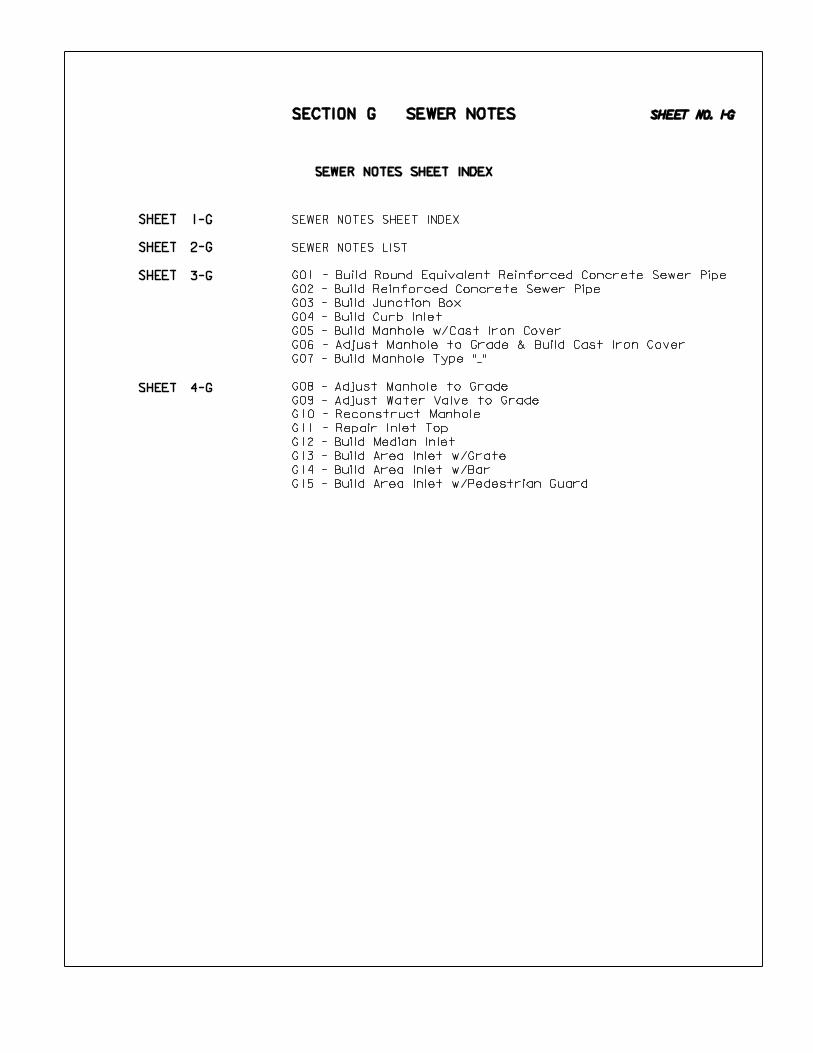
SHEET
SHEET
SHEET
SHEET
SECTION G SEWER NOTES
G08 - Adjust Manhole to Grade
G09 - Adjust Water Valve to Grade
G10 - Reconstruct Manhole
G11 - Repair Inlet Top
G12 - Build Median Inlet
G13 - Build Area Inlet w/Grate
G14 - Build Area Inlet w/Bar
G15 - Build Area Inlet w/Pedestrian Guard
G01 - Build Round Equivalent Reinforced Concrete Sewer Pipe
G02 - Build Reinforced Concrete Sewer Pipe
G03 - Build Junction Box
G04 - Build Curb Inlet
G05 - Build Manhole w/Cast Iron Cover
G06 - Adjust Manhole to Grade & Build Cast Iron Cover
G07 - Build Manhole Type "_"
SEWER NOTES SHEET INDEX
SEWER NOTES SHEET INDEX
SEWER NOTES LIST
SHEET NO. 1-G
1-G
2-G
3-G
4-G

SECTION G
SECTION G SEWER NOTES
G08 - Adjust Manhole to Grade
G09 - Adjust Water Valve to Grade
G10 - Reconstruct Manhole
G11 - Repair Inlet Top
G12 - Build Median Inlet
G13 - Build Area Inlet w/Grate
G14 - Build Area Inlet w/Bar
G15 - Build Area Inlet w/Pedestrian Guard
G01 - Build Round Equivalent Reinforced Concrete Sewer Pipe
G02 - Build Reinforced Concrete Sewer Pipe
G03 - Build Junction Box
G04 - Build Curb Inlet
G05 - Build Manhole w/Cast Iron Cover
G06 - Adjust Manhole to Grade & Build Cast Iron Cover
G07 - Build Manhole Type "_"
SEWER NOTES LIST
SHEET NO. 2-G

INFORMATION ONLY CELL NAME
G01
G02
G03
G04
G05
Sta. ___+__
Build __" ‘ __’ Round
Equivalent Reinforced
Concrete Sewer Pipe w/Inlet
& Outlet in Curb Inlet.
1
Sta. ___+__
Build Curb Inlet.
Plan 443-R_. X = __’-__’’,
A = __’-__’’, Y = __’-__’’
Sta. ___+__
Build Manhole w/Cast Iron
Cover, Type __, Frame &
Flange. Plan 435-R_.
Sta. ___+__
Adjust Manhole to Grade &
Build Cast Iron Cover,
Type __ Frame & Flange.
Plan 435-R_.
Sta. ___+__
Build __" ‘ __’
Reinforced Concrete Sewer
Pipe w/Inlet in Curb Inlet
& Outlet in Junction Box.
Sta. ___+__
Build Junction Box,
Plan 443-R_. X = __’-__",
Y = __’-__" ‘ Y = __’-__"
Sta. ___+__
Build Manhole, Type _ with
Cast Iron Cover, Type _ &
Frame, Type _. Plan 435-R_.
SECTION G SEWER NOTES
TYPES OF MANHOLE: ’’A’’, ’’B’’ AND ’’C’’
Types "A" & "B" are round
Type "C" is square
Excavation is subsidiary for Sewers, Junction Boxes,
Catch Basins, Inlets, Retaining Walls & Steps.
Refer to Sheet 3-C2 for Pipe-Arch to Round Equivalent
conversion table and example notes.
Keep Pipe notes separate from Junction Box notes.
Junction Box may require either a Special Plan or
a Standard Plan.
This example indicates the Type of Manhole is optional.
The Type of Cast Iron Cover will be specified as:
Type A - (Storm Sewer)
or
Type B (Sanitary Sewer)
Telescopic Type: Frame & Flange, Type I
Non-Telescopic Type: Frame only, Type II Ring
Type III : Normally used outside of pavement.
Use Type of Manhole only if you want to eliminate
the Contractors option.
G06
G07
SHEET NO. 3-G

INFORMATION ONLY CELL NAME
Sta. ___+__
Build Area Inlet w/Pedestrian
Guard. Special Plan _C.
Sta. ___+__
Adjust Manhole to Grade.
Sta. ___+__
Adjust Water Valve to Grade.
Sta. ___+__
Reconstruct Manhole.
Plan 435-R1.
Sta. ___+__
Repair Inlet Top.
Special Plan _C.
Sta. ___+__
Build Area Inlet with Bar.
Special Plan _C. X= __’-__"
Sta. ___+__
Build Median Inlet.
Special Plan _C. X = __’-__"
SECTION G SEWER NOTES
Obtain these Special Plans from Drafting Dept.:
Special Plan 4330 1 "Area Inlet with Bar"
Special Plan 4333 1 "Area Inlet with Grate"
Obtain Median Inlet Special Plan from Bridge Dept.
Sta. ___+__
Build Area Inlet with Grate,
Type __. Special Plan _C.
X= __’-__"
G08
G09
G10
G11
G12
G13
G14
G15
SHEET NO. 4-G

SHEET
SHEET
SHEET
SHEET
SHEET
SECTION H REMOVAL NOTES
H18 - Abandon Well
H19 - Remove Curb Inlet
H20 - Remove Retaining Wall
H21 - Remove __ Lin. Ft. of Retaining Wall
H22 - Remove __ Lin. Ft. of Concrete Barriers
H23 - Remove Sign, Post & Footing
Delineator Removal Information
H01 - Remove Fence
H02 - Remove Discharge Structure
H03 - Remove Concrete Ditch Liner
H04 - Remove Driveway
H05 - Remove Asphalt Surface
H06 - Remove Concrete Median Surfacing
H07 - Remove Pavement
H08 - Remove Concrete Pavement & Crush
H09 - Remove Walk
H10 - Remove Combination Curb and Gutter
H11 - Remove Curb See Sheet 2-T
H12 - Remove Curb
H13 - Remove Guardrail (Sta.)
H14 - Remove Guardrail (Sta. to Sta.)
H15 - Remove Guard Posts
H16 - Clear Tract
H17 - Remove Building
REMOVAL NOTES SHEET INDEX
REMOVAL NOTES SHEET INDEX
REMOVAL NOTES LIST
SHEET NO. 1-H
1-H
2-H
3-H
4-H
5-H
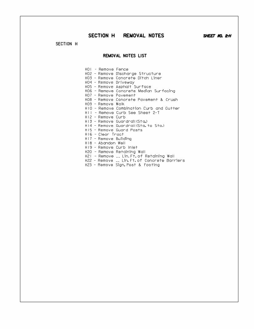
SECTION H
SECTION H REMOVAL NOTES
H01 - Remove Fence
H02 - Remove Discharge Structure
H03 - Remove Concrete Ditch Liner
H04 - Remove Driveway
H05 - Remove Asphalt Surface
H06 - Remove Concrete Median Surfacing
H07 - Remove Pavement
H08 - Remove Concrete Pavement & Crush
H09 - Remove Walk
H10 - Remove Combination Curb and Gutter
H11 - Remove Curb See Sheet 2-T
H12 - Remove Curb
H13 - Remove Guardrail (Sta.)
H14 - Remove Guardrail (Sta. to Sta.)
H15 - Remove Guard Posts
H16 - Clear Tract
H17 - Remove Building
H18 - Abandon Well
H19 - Remove Curb Inlet
H20 - Remove Retaining Wall
H21 - Remove __ Lin. Ft. of Retaining Wall
H22 - Remove __ Lin. Ft. of Concrete Barriers
H23 - Remove Sign, Post & Footing
REMOVAL NOTES LIST
SHEET NO. 2-H

INFORMATION ONLY CELL NAME
H01
H02
H09
Sta. ___+__
Remove __ Lin. Ft. of Fence.
Remove.
Sta. ___+__
Remove __ Sq. Yds. of
Driveway.
Sta. ___+__
Remove __ Sq. Yds. of
Asphalt Surface.
Sta. ___+__
Remove __ Sq. Yds. of
Concrete Median Surfacing.
Sta. ___+__ to
Sta. ___+__
Remove __ Sq. Yds. of
Pavement.
Sta. ___+__ to
Sta. ___+__ Lt.
Remove __ Sq. Yds. of
Concrete Ditch Liner.
Sta. ___+__ to
Sta. ___+__ Lt.
Remove __ Sq. Yds. of Walk.
SECTION H REMOVAL NOTES
Sta. ___+__ to
Sta. ___+__
Remove __ Sq. Yds. of
Concrete Pavement & Crush.
Asphalt Median surfacing is removed as
’ASPHALT SURFACE’.
The Existing Topography should indicate the type of
Fence (such as Wood, Chain Link, or Ornamental) IF
it requires a special removal note.
Remove Ditch ’LINER’ by Sq. Yds.
Build Ditch ’LINING’ by Lin. Ft.
Discharge Structure is removed as 1-each.
This note can be used to remove "Approach Slab Drains".
It can include the Inlet and also the Outlet Pipe. The
Crossraod Pipe needs to be removed separately.
For removing Concrete or Asphalt driveway DO NOT specify
the type of material to be removed. If asphalt can be
buried in vicinity of driveway, a note is NOT required
(Full Grading or Safety Section).
For the exception to this note, see Temporary Road
Removal information in Section F.
’PAVEMENT’ includes Concrete, Asphalt & Brick.
If ’BRICK SURFACE’ is to be removed a Special Provision
is required.
Do NOT show the thickness of the pavement to be removed
on the plans.
(Intergral Curb can also be removed with the Rdwy. Pvm’t)
This applies to Existing Asphalt. If asphalt surface is to
be removed by ’Milling’ it will be shown on the 2-T sheet
and addressed in the Special Provisions. In this case a
removal note on the Plans is NOT required.
NOTE:
Removing Earth Drives does NOT require a note.
On a rural project, you do not need a note if all of the
roadway is being removed, nor do you need to cross hatch
the roadway. But, if the roadway is being partially removed,
or various segments are being removed, a note is required
and the roadway area should show removal cross hatching.
H03
H04
HO5
H06
H07
H08
STA. ___+__
DISCHARGE STRUCTURE.
SHEET NO. 3-H
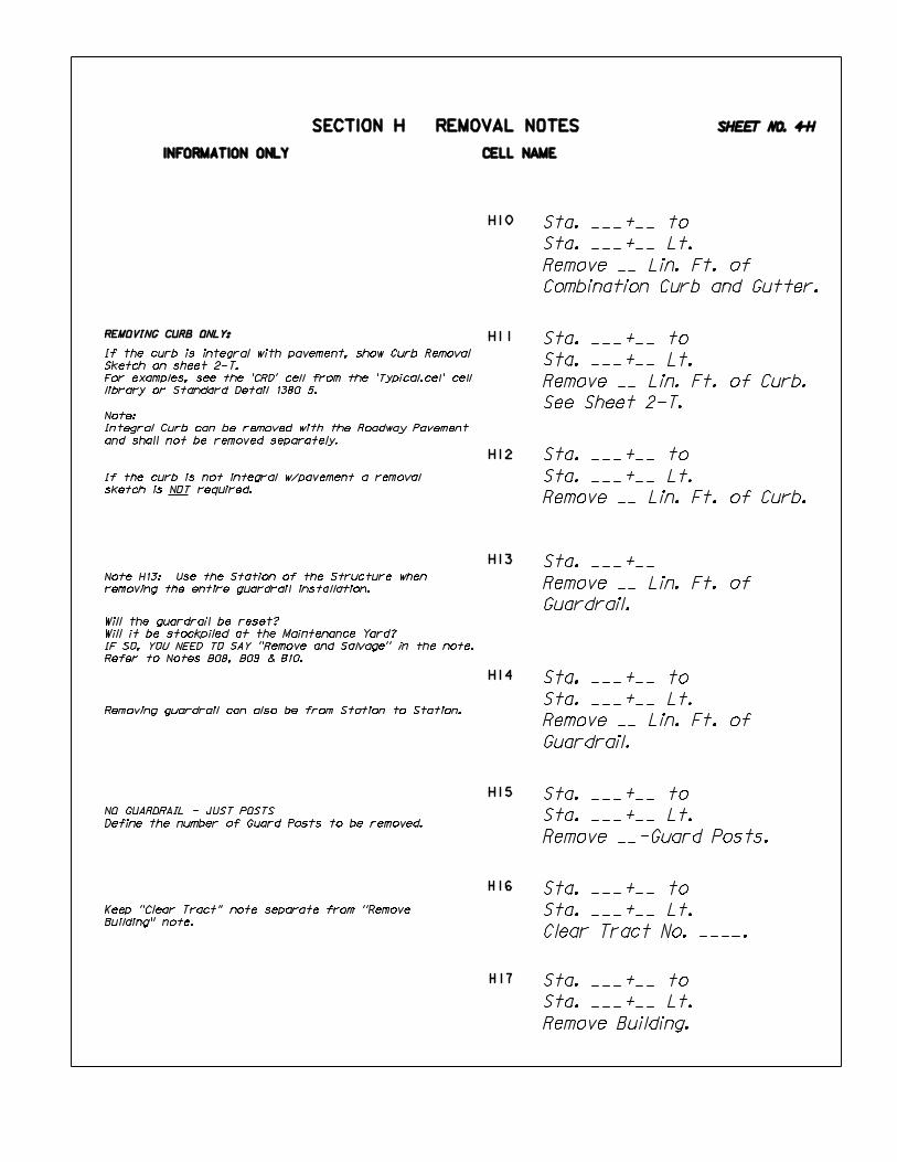
INFORMATION ONLY CELL NAME
Sta. ___+__ to
Sta. ___+__ Lt.
Remove __ Lin. Ft. of Curb.
Sta. ___+__ to
Sta. ___+__ Lt.
Remove __ Lin. Ft. of
Guardrail.
Sta. ___+__ to
Sta. ___+__ Lt.
Remove __-Guard Posts.
Sta. ___+__ to
Sta. ___+__ Lt.
Clear Tract No. ____.
Sta. ___+__ to
Sta. ___+__ Lt.
Remove Building.
Sta. ___+__ to
Sta. ___+__ Lt.
Remove __ Lin. Ft. of
Combination Curb and Gutter.
Sta. ___+__ to
Sta. ___+__ Lt.
Remove __ Lin. Ft. of Curb.
See Sheet 2-T.
SECTION H REMOVAL NOTES
If the curb is not integral w/pavement a removal
sketch is NOT required.
Note H13: Use the Station of the Structure when
removing the entire guardrail installation.
Removing guardrail can also be from Station to Station.
NO GUARDRAIL - JUST POSTS
Define the number of Guard Posts to be removed.
Will the guardrail be reset?
Will it be stockpiled at the Maintenance Yard?
IF SO, YOU NEED TO SAY "Remove and Salvage" in the note.
Refer to Notes B08, B09 & B10.
Sta. ___+__
Remove __ Lin. Ft. of
Guardrail.
REMOVING CURB ONLY:
Note:
Integral Curb can be removed with the Roadway Pavement
and shall not be removed separately.
If the curb is integral with pavement, show Curb Removal
Sketch on sheet 2-T.
For examples, see the ’CRD’ cell from the ’Typical.cel’ cell
library or Standard Detail 1380 5.
Keep "Clear Tract" note separate from "Remove
Building" note.
H10
H11
H12
H13
H14
H15
H16
H17
SHEET NO. 4-H

SN20
INFORMATION ONLY CELL NAME
Sta. ___+__ Lt.
Remove Curb Inlet.
Sta. ___+__ to
Sta. ___+__ Lt.
Remove Retaining Wall.
Sta. ___+__ to
Sta. ___+__ Lt.
Remove __ Lin. Ft. of
Retaining Wall.
Sta. ___+__ to
Sta. ___+__ Lt.
Remove __ Lin. Ft. of
Concrete Barriers.
Sta. ___+__ Lt.
Abandon Well.
SECTION H REMOVAL NOTES
FOR INFORMATION ONLY
When Barriers were placed in Lieu of Guardrail
on a previous project. (Note H22)
When removing a Curb Inlet, if a pipe is to be abandoned,
you DO NOT need to call for the Plug & Abandon Special
Plan, as it is subsidiary. See Std. Spec Book Section 203.
Paid for as 1-Each when removing the entire wall.
Paid for as Lin. Ft. when partially removing the wall.
WHEN THE CONTRACTOR REMOVES DELINEATORS
A note is NOT needed for removing delineators.
This information will be given on the Computation Sheet
and in a Special Provision.
DELINEATOR REMOVAL INFORMATION
STD.CEL
WHEN STATE FORCES REMOVE DELINEATORS
Use Standard Note SN20 from the ’std.cel’ cell library.
Sta. ___+__ Lt.
Remove Sign, Post & Footing.
H23
H18
H19
H20
H21
H22
SHEET NO. 5-H
All existing delineators on this project
will be removed by state forces.

SHEET
SHEET
SHEET
SHEET
SHEET
SECTION J BRIDGE NOTES
BRIDGE NOTES SHEET INDEX
BRIDGE NOTES LIST
BRIDGE NOTES SHEET INDEX
J01 - Dbl. Tee Beam Bridge (Prelim. Note)
J02 - Conc. Deck Bridge (Prelim. Note)
J03 - Build Steel Girder Bridge
J04 - Build Welded Plate Bridge
J05 - Transverse Joist Bridge (Prelim. Note)
J06 - Build Continuous Girder Bridge
J07 - Prestressed Girder Bridge (Prelim. Note)
J08 - Dbl. Prestressed Girder Bridge (Widen)
J09 - Build Multi-Span Deck Steel Girder Bridge
J10 - Treated Timber Bridge (Prelim. Note)
J11 - Pony Truss Bridge (Prelim. Note)
J12 - Prestressed Concrete Girder Bridge (Prelim. Note)
J13 - Deck Steel Girder & Timber Bridge (Prelim. Note)
J14 - Cont. Concrete Slab Bridge (Prelim. Note)
J15 - Build Conc. Slab Bridge on Skew
J16 - Build Continous Conc. Slab Bridge
J17 - Build Temporary Bridge
J18 - Erect Temporary Bridge
SHEET NO. 1-J
1-J
2-J
3-J
4-J
5-J

SECTION J BRIDGE NOTES
BRIDGE NOTES LIST
J01 - Dbl. Tee Beam Bridge (Prelim. Note)
J02 - Conc. Deck Bridge (Prelim. Note)
J03 - Build Steel Girder Bridge
J04 - Build Welded Plate Bridge
J05 - Transverse Joist Bridge (Prelim. Note)
J06 - Build Continuous Girder Bridge
J07 - Prestressed Girder Bridge (Prelim. Note)
J08 - Dbl. Prestressed Girder Bridge (Widen)
J09 - Build Multi-Span Deck Steel Girder Bridge
J10 - Treated Timber Bridge (Prelim. Note)
J11 - Pony Truss Bridge (Prelim. Note)
J12 - Prestressed Concrete Girder Bridge (Prelim. Note)
J13 - Deck Steel Girder & Timber Bridge (Prelim. Note)
J14 - Cont. Concrete Slab Bridge (Prelim. Note)
J15 - Build Conc. Slab Bridge on Skew
J16 - Build Continous Conc. Slab Bridge
J17 - Build Temporary Bridge
J18 - Erect Temporary Bridge
SHEET NO. 2-J

INFORMATION ONLY CELL NAME
J01
J02
J03
J04
J05
J06
J07
J08
Sta. ___+__ #(S______)
Build _-__’-__’’ & _-__’-__’’
Spans Deck Steel Girder
Bridge (__’ Roadway).
Special Plan _.
Sta. ___+__ #(S_____)
Build _-__’-__" & _-__’-__"
Spans Continuous Girder
Bridge (__’ Roadway).
Special Plan _.
(Widen to __’ Roadway).
Special Plan _.
Sta. ___+__ #(S______)
Build _-__’-__’’ & _-__’-__’’
Spans Continuous Welded
Plate Bridge Composite Type.
(__’ Rdwy). Special Plan _.
SECTION J BRIDGE NOTES
Include the Structure No. with the Bridge Note.
BRIDGE PLANS ONLY
Note that the Special Plan No. is NOT followed by
the character ’’C’’.
STA. ___+__ #(S _____ )
_-___’-__" & _-___’-__" SPANS.
DBL. TEE BEAM BR. W/___’ RDWY.
STA. ___+__ #(S_______)
_-___’-__’’ SPANS TRANSVERSE
JOIST BRIDGE.
STA. ___+__ #(S_______)
_-___’-__’’ & _-___’-__’’ SPANS
DBL. PRESTRESSED GIRDER BR.
W/__’ RDWY.
STA. ___+__ #(S_______)
_-___’ - __’ & _-___’ - __" SPANS
DBL. PRESTRESSED GIRDER BR.
W/__’ RDWY.
STA. ___+__ #(S_______)
_-___’-__’’ SPANS CONC. DECK BR.
W/__’ RDWY.
ABBREVIATIONWORD
Bridge
Tee
Double
Concrete
Deck
Steel
Continuous
Plate
Viaduct
Wood
Girder
Roadway
BR.
’’T’’
DBL.
CONC.
DK.
STL.
CONT.
PL.
VIA.
WD.
GRD.
RDWY.
ABBREVIATIONS FOR EXISTING BRIDGE NOTES
SHEET NO. 3-J

INFORMATION ONLY CELL NAME
J09
J11
J12
J13
J14
J15
J16
J10
Sta. ___+__ #(S______)
Build _-__’__" & _-__’__"
Spans Concrete Slab Bridge
on __^ Skew (__’ Roadway).
Special Plan _.
Sta. ___+__ #(S______)
Build _-__’__" & _-__’__"
Spans Concrete Slab
Bridge Continous Type.
Special Plan _.
SECTION J BRIDGE NOTES
Sta. ___+__ #(S______)
Build Multi-Span Deck Steel
Girder Viaduct Continuous
Composite Type (__’ Roadway).
Special Plan _.
STA. ___+__ #(S_______)
_-___’-__’’ & _-___’-__’’ SPANS
TREATED TIMBER BR. W/__’ RDWY.
STA. ___+__ #(S_______)
_-___’-__’’ SPANS PONY TRUSS BR.
STA. ___+__ #(S_______)
_-___’-__’’ SPANS PRESTRESSED
CONC. GIRDER BR. W/__’ RDWY.
STA. ___+__ #(S_______)
_-___’-__’’ SPANS DECK STEEL
GIRDER & _-___’-__’’ SPANS
TIMBER BR. W/__’ RDWY.
STA. ___+__ #(S_______)
_-___’-__’’ SPANS CONT. CONC.
SLAB BR. ON __^ SKEW W/__’ RDWY.
SHEET NO. 4-J

INFORMATION ONLY CELL NAME
J17
J18
Sta. ___+__
Build Temporary Bridge.
Special Plan _.
Sta. ___+__
Erect Temporary Bridge.
Special Plan _.
TEMPORARY BRIDGES
SECTION J BRIDGE NOTES
NO Removal note - It is handled by Special Provision.
You do not call out the size, it is addressed
in the Special Provisions.
Use ’Build’ when the Temp. Bridge is furnished
by the Contractor.
Use ’Erect’ when the Temp. Bridge is furnished
by the State.
SHEET NO. 5-J