increasing drilling rate in deep …ttinc10.qwestoffice.net/papers/arma2000.pdfincreasing drilling...
TRANSCRIPT

INCREASING DRILLING RATE IN DEEP BOREHOLES BY IMPULSIVE DEPRESSURIZATION
© Tempress Technologies Inc. 2000
J.J. Kollé,
Abstract Drilling rates decrease continuously with depth in a fluid-filled borehole. The mechanical shearing of rock during drilling causes pore volume dilatation at the cutting face. Since pore water is relatively incompressible and boreholes are pressurized, dilatation leads to diffusion-limited confining pressures, which strengthen low permeability rock. Impulsive depressurization of the borehole can result in effective tensile stresses in the rock face that overcome the confining pressure. Pore pressure diffusion and lithostatic compressive stresses reduce the magnitude of the effective tensile stress pulse. A series of small-scale pressure drilling experiments were carried out using a prototype flow cycling valve. Tests were carried out in shale, sandstone, and granite, which is not. Suction pressure pulses cause a large increase in drilling rates in shale; and significant increases in drilling rates in sandstone and granite. The results reflect a combination of reduced pressure and hydraulic impulsive loading effects.
Introduction Conventional rotary drilling is slowed by the confining pressure exerted by the column of mud in the borehole. The bottom hole pressure in a hole drilled for oil or gas is typically maintained at a value which is equal to, or slightly higher than the pore pressure of fluids (water, oil or natural gas) in the formation being drilled. The confinement associated with this static differential pressure causes an increase in the drilling strength of rock. During drilling, the rock ahead of the cutter is rapidly deformed. The dilatation associated with rock deformation leads to a dynamic pressure differential, between the borehole fluid and the pores in the rock being cut, that can equal the total borehole pressure. This dynamic confinement pressure increases the strength and plasticity of rock, reducing the efficiency of indentation and shear cutting (Detournay and Atkinson 1991, Kollé, 1993). The greatest effect of confining pressure occurs in shale, which account for over 75% of the rock encountered during oil and gas drilling, so this behavior can account for much of the decline in drilling rate observed in deep wells.
Drilling experience has demonstrated that significant increases in drilling rate can be achieved by underbalanced drilling (in which the borehole pressure during drilling is smaller than the formation pressure). This is achieved by reducing the amount of weighting material added to the drilling mud or by using light-weight drilling fluids such as gas or foam to drill. Underbalanced drilling exposes the entire open hole section to low pressure, which reduces borehole stability and formation fluid control.
An ideal drilling system would create a low-pressure region that is limited to the hole bottom while normal or overbalanced conditions are maintained above the bit to control formation fluids. The mud jet on a modern jet bit accomplishes this because of turbulent pressure fluctuations on the hole bottom around the jet impact. Wells (1985) has shown that the magnitude of pressure fluctuations can be 20% of the jet pressure and that these pressures will lift cuttings held to the hole bottom by differential hold-down pressures. The size of the low pressure region in turbulence is limited by the eddy size and is typically limited to a small annular region around the jet. Pressure reduction over the entire bit face should have a greater effect on chip removal. There have been attempts to achieve this using reverse flow bits, however the bottom hole pressure reductions achieved have been relatively minor (Bizanti 1987). Ruhle (1996) describes a downhole suction pump designed to generate low pressure around a drill bit in order to induce
1

rock spallation. The pump is actuated by vertical oscillation of a drill string, which may be impractical in deep boreholes.
Drilling mud is normally pumped through a drill bit to remove cuttings from the hole bottom and transport them to the surface. When directed through high-speed flow courses, the mud flow contains significant kinetic energy, which can be converted into a suction pressure pulse by momentarily interrupting the flow with a valve as shown in Figure 1. This generates a positive pressure pulse upstream of the flow interruption and a suction pulse downstream. The suction pulse magnitude can be quite high because of the low compressibility of water-based drilling mud.
Valve Open Valve Closed
Enhanced
Seismic Pulse
PDC orTricone Bit
Flow CyclingValve
High-SpeedFlow
Poppet
Rock Breaking
Pulse
Hydraulic Thrust
PressureSuction
Exhaust
Figure 1. Generation of suction pulses using a mud flow-cycling valve. An analysis of the mechanics of suction pulse propagation into poro-elastic rock was carried out to determine the pulse magnitude, rise time and duration required to benefit the drilling process. The effective stress around a borehole subject to differential pressure pulses is compared with the tensile strength of rock in order to estimate of the pressure magnitude required to induce damage. Pore pressure diffusion considerations are used to determine the rate at which pressure changes in the rock in order to determine an appropriate pulse time history. Finally, the lithostatic stress around a borehole is evaluated to see how the effective stress varies with depth into the rock surface in order to estimate the depth of the damage zone. The rock mechanics analysis is followed by a discussion of suction pulse generation using a flow interuption valve. A small-scale prototype flow-cycling valve was built and used to demonstrate the effects of suction pulses on drilling rates in shale, sandstone and granite. The analysis and pressure drilling tests provided the basis for the development of a full-scale drilling tool, shown in Figure 2.
2
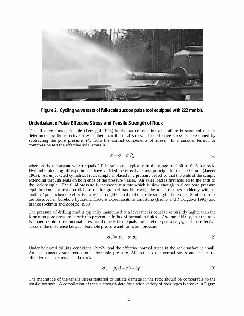
Figure 2. Cycling valve tests of full-scale suction pulse tool equipped with 222 mm bit.
Underbalance Pulse Effective Stress and Tensile Strength of Rock The effective stress principle (Terzaghi 1943) holds that deformation and failure in saturated rock is determined by the effective stress rather than the total stress. The effective stress is determined by subtracting the pore pressure, Po, from the normal components of stress. In a uniaxial tension or compression test the effective axial stress is
σ σ α'= − Po , (1)
where α is a constant which equals 1.0 in soils and typically in the range of 0.80 to 0.95 for rock. Hydraulic pinching-off experiments have verified the effective stress principle for tensile failure. (Jaeger 1963). An unjacketed cylindrical rock sample is placed in a pressure vessel so that the ends of the sample extending through seals on both ends of the pressure vessel. An axial load is first applied to the ends of the rock sample. The fluid pressure is increased at a rate which is slow enough to allow pore pressure equilibration. In tests on diabase (a fine-grained basaltic rock), the rock fractures suddenly with an audible “pop” when the effective stress is roughly equal to the tensile strength of the rock. Similar results are observed in borehole hydraulic fracture experiments in sandstone (Bruno and Nakagawa 1991) and granite (Schmitt and Zoback 1989).
The pressure of drilling mud is typically maintained at a level that is equal to or slightly higher than the formation pore pressure in order to prevent an influx of formation fluids. Assume initially, that the rock is impermeable so the normal stress on the rock face equals the borehole pressure, pb, and the effective stress is the difference between borehole pressure and formation pressure.
obn pp ' ασ −= (2)
Under balanced drilling conditions, Pb=Po, and the effective normal stress in the rock surface is small. An instantaneous step reduction in borehole pressure, ΔP, reduces the normal stress and can cause effective tensile stresses in the rock.
ppbn Δ−−=′ )1( ασ . (3)
The magnitude of the tensile stress required to initiate damage in the rock should be comparable to the tensile strength. A compilation of tensile strength data for a wide variety of rock types is shown in Figure
3

2 (Lockner 1995). The plot indicates the range of observed strength values about a median value for each rock type. The upper limit for tensile strength of sedimentary rocks is about 35 MPa and most of these rock types have strength which is much lower. All of the shales and sandstones tested have a tensile strength of under 22 MPa. Shale accounts for over 75% of the formations drilled for oil and gas (Steiger and Leung 1992) so underbalance pressure pulses of 20 MPa should be effective for drilling most shale, sandstone and limestone.
Figure 3. Distribution of tensile strength in rock (Lockner 1995). The effect of pressure reductions on fixed cutter drilling rates can be estimated from data on the effect of fluid pressure on drilling rate. Figure 3 shows the drilling strength – defined as indentation load divided by cut area – for Mancos Shale (Kollé 1996). At 20 MPa ambient pressure the drilling strength is three times greater than at zero ambient pressure. Suction pulses of 20 MPa magnitude should therefore cause a threefold increase in drilling rate.
0
200
400
600
800
1000
0 20 40 60 8Pressure, MPa
Dril
ling
Stre
ngth
, MP
a
0
0.1 0.3 0.5
Cut Depth, mm
Figure 4. Mancos Shale drilling strength versus pressure and cut depth, data from Kollé (1996).
4

Pore Pressure Diffusion We have so far assumed that the suction pressure pulse is applied instantaneously and that the rock is impermeable. In permeable rock, the suction pulse will diffuse and the tensile stress magnitude will be a function of time and depth. The one-dimensional problem of planar diffusion of a pressure pulse into an infinite half space has the same form as the familiar heat diffusion equation (Bear 1972). The transient problem is described by the partial differential equation
Dpz
pt
∂∂
∂∂2 = (4)
where D is the is the formation pore pressure diffusivity, given by
Dk
=μ φ β
; (5)
k is permeability, μ is pore fluid viscosity and β is the pore fluid compressibility. For boundary conditions we assume a step change in pore pressure
t p z pt p t p
o
o p= => =
0 00 0 : :
( , )( , ) Δ−
. (6)
These equations have a solution, given in Churchill (1972),
p p p erfczDto= − ⋅
⎛
⎝⎜
⎞
⎠⎟Δ
2 (7)
where erfc(x) is the co-error function defined as
erfc x dx
( ) exp( )= − −∫12 2
0πζ ζ (8)
A characteristic pore pressure diffusion depth can be defined as the depth at which the pressure will change 10% and is given by
z t( ) .10%, 2 3= Dt . (9)
Table 1 lists the 10% pore pressure diffusion depth at a time of 1 millisecond for a variety of rock types. For the most part, the pore pressure diffusion depth is limited to a few millimeters. This means that if the pressure drop time is less than 1 millisecond, the differential pressure would be 90% of the applied pressure drop at a depth of a few millimeters. This depth scale is comparable to the depth of cut of a typical fixed cutter, or roller cone drill bit. In rocks with very low permeability the diffusion depth is much smaller. In a rock such as Berea Sandstone, which has high permeability the characteristic diffusion depth is over 100 mm and pressure pulses should have little effect on drilling.
5

Table 1. Pore pressure diffusion and strength data for rock.
Rock Type Tensile Strength, MPa
D, m2/s z(10%, .001s), mm
Carthage Marble 10 9.0 x 10⁻³ 7
Sierra White Granite 13 10-2 - 10-5 7 - 0.2
Colton Sandstone 7 1.0 x 10⁻² 7
Berea Sandstone 6 3.3 132
Mancos Shale 8 1.4 x 10⁻³ 2.3
The more general case of a transient change in pressure F(t) at the rock surface is provided by Churchill (1972). The boundary conditions for the pore pressure, p(z,t) are:
p t F t p z t p zz
( , ) ( ) lim ( , ) ( , )0 0= 0 0= =→∞
, , and (10)
The general solution is
p z t F tz
Dd( , ) exp( )= −
⎛
⎝⎜
⎞
⎠⎟ −
∞
∫24
2
22
π ζζ ζ
λ
, (11)
which reduces to the co-error function when F(t) is a constant. Since F(t) describes the variation in pressure at the surface, the differential pore pressure is
)(),( tFtzpp −=Δ . (12)
Figure 5 shows the differential pressure at depths of 1-mm and 5-mm in Mancos Shale when the surface is subject to a pressure drop with a triangular pulse profile and a rise time of 1 millisecond. The differential pressure at a depth of 5-mm mirrors the surface pressure pulse exactly. The effects of pore pressure diffusion are seen as a smaller differential pressure followed by an overshot in pressure at a depth of 1-mm.
6

0 0.001 0.002 0.003 0.004 0.0050.5
0
0.5
1
Time, s
Differential Pressure
5-mm
1-mm
Figure 5. Differential pore pressure at a depth of 1- and 5-mm from the surface of Mancos Shale subject to an underbalance pressure pulse with a linear rise time of 1 ms and a linear drop of 1 ms. The pressure pulse should be followed by a longer period of normal pressure during which the pore pressure re-equilibrates. The pore pressure diffusion time also determines the spacing between pressure pulses. The time required for the pore pressure to re-equilibrate is an order of magnitude greater than the time associated with a 10% pressure change. The pressure pulses should thus be separated by a time which is 10 milliseconds or greater to ensure that the pore pressure re-equilibrates prior to the next pulse.
Suction Pulse Generation The analysis of suction pulse mechanics indicates that pressure profiles should have the following characteristics in order to enhance drilling rates:
1. Amplitude of over 10 MPa
2. A rapid drop in pressure occurring in a time of less than a millisecond
3. A return to normal borehole pressures for a period of 10 milliseconds or more
These pulse characteristics can be generated by interrupting the flow of water-based drilling mud in a conduit downstream of the drill bit. Water-hammer occurs when the kinetic energy of flow in a closed conduit is converted into the elastic energy of compression/decompression of the fluid. If the initial flow velocity is v, the magnitude of the water-hammer pressure pulse is approximated by
βρvp =Δ , (13)
here β is the compressibility of the fluid and ρ is the density (cf. Trostmann 1996). The compressibility and density of water are not constant with pressure, however this equation is accurate to within 8% at pressures of up to 30 MPa.
The duration of the pressure pulse is determined by the two-way travel time of acoustic waves in the flow conduit. The speed of sound in water is about 1500 m/s so the duration of a pressure pulse in a conduit with a length of 1 m would be about 1.0 milliseconds. The suction pulse drill would incorporate a flow course length of at least 1 m to ensure that the pressure pulses have a duration on the order of 2 ms.
7

The suction pulse drilling test stand is shown in Figure 6. High pressure water is supplied to the test stand from a triplex pump. A poppet inside the flow cycling valve periodically interrupts the flow from the drill to the bit and diverts it to the valve exhaust port. Closing the poppet causes a secondary valve to shift, which then shifts the poppet back to the open position. When the cycling valve poppet is open, flow enters through the drill rod and is discharged through open ports on the bit. The high speed flow is directed through flow courses around the bit into an annular area and out through the seal housing into the suction pressure line with a length that can be varied from 100-mm to 1.5-m. The intensity of the pressure pulse is related to the flow velocity in the suction pulse line while the pulse duration is related to the length of the line. High pressure is maintained in the pressure vessel by directing the flow from the suction pressure line and cycling valve exhaust through an adjustable choke. Hydraulic controls allow the cycling to be turned on and off in order to compare drilling rates with and without the suction pressure pulses.
Figure 6. Small-scale pressure drilling test stand layout. Rock samples are 50-mm in diameter and the drill bit is 8.7-mm in diameter. The pressure vessel is designed to operate at 35 MPa.
Figure 6 shows an example of a series of suction pressure pulses generated in a borehole in shale by the prototype flow cycling valve. The pressure pulses occur at a cycle rate of 47 Hz. The hydraulic power associated with each pulse is .75 J and the power level is 35 W in this example.
8

Pulse 10, Pi=21 MPai
-20.0
-15.0
-10.0
-5.0
0.0
5.0
0 50 100 150 200Time, milliseconds
Pres
sure
, MPa
Figure 7. Example of 35 W suction pulse train generated by a flow interruption valve in combination with a high speed flow course. (1000 psi = 6.9 MPa).
Application of a suction pressure pulse results in a mechanical thrust on the bit that is related to the area of the drill rod (drod = 8 mm) and the pulse magnitude. The impulsive thrust is
(14) ppAF rodh Δ×=Δ= −6102.50
At a suction pulse pressure of 21 MPa the thrust force is 1050 N, which is about much higher than the constant thrust level of 200 N used for most of the drilling tests.
DRILLING TEST RESULTS The drilling experiments were carried out in Mancos Shale, Colton Sandstone and Sierra White Granite. The nominal properties of these rock types are listed in Table 1. The tensile strengths are assumed to be 10% of compressive strength (c.f. Jaeger and Cook 1976 p. 190). The tensile strength of Sierra White Granite is from a Brazil test.
Rock Disruption Tests An initial series of tests involved the application of pressure pulses while the bit was fixed about 1 mm above the rock surface. These tests were designed to determine whether it was possible to remove rock by pressure pulses alone. Rock disruption tests carried out on Colton Sandstone, Mancos Shale and Sierra White Granite indicated no apparent surface damage resulting from pulse magnitudes of up to 20 MPa (2890 psi). These pressure pulse magnitude are significantly greater than the tensile strength of either the shale or sandstone.
Some surface disruption was observed on the upper surface of the shale samples following subsequent suction pulse drilling test. Figure 7 shows an example of a pit on the sample surface. This pit appears to be the result of rock spalling from a flaw located at a depth of 1 mm beneath the surface. The number and size of naturally occurring flaws increases with the scale of the rock so this phenomenon may become more pronounced when suction pulses are applied over a full-scale borehole.
9

Figure 8. Surface pit in Mancos Shale sample after suction pulse drilling experiment. Pit is above and to the right of the 8.7 mm diameter borehole.
Drilling Tests with Backrake Cutter Drilling tests were carried out using a 20 degree negative backrake carbide cutter bit shown in Figure 8. Drilling tests in Mancos Shale were carried out at two thrust levels, and at varying pulse amplitudes. The drilling rates are shown in Figure 9. The drilling rate with 200 N thrust shows an increase by a factor of three at around 10 MPa. When suction pulses are applied at zero thrust, the penetration rate of the backrake cutter is essentially the same as with 200 N thrust.
Figure 9. 8.7-mm diameter, 20 degree backrake cutter microbit used for Mancos Shale and Colton Sandstone drilling tests.
10

0.0
0.1
0.2
0.3
0.4
0.5
0.6
0 5 10 15 20 25
Suction Pulse Magnitude, MPa
Pen
etra
tion
Rat
e, m
m/re
v200
0
Thrust, N
Figure 10. Mancos Shale drilling with backrake cutter at 60 rpm, 21 MPa ambient pressure. Figure 10 shows the drilling strength data for Mancos Shale plotted as a function of the ambient pressure (21 MPa) minus the pulse magnitude. The drilling strength drops from around 200 MPa to 50 MPa when the pulse magnitude exceeds 10 MPa. Referring to Figure 3, we see that these reductions in drilling strength are consistent with the effect of reducing dynamic confining pressures by an amount equal to the pulse amplitude.
A single drilling test was carried with the backrake cutter out in a sample of Colton Sandstone. This rock drilled rapidly with a drilling strength of only 13 MPa at an ambient pressure of 21 MPa. The application of 16 MPa suction pulses reduced the drilling strength to 4 MPa – a factor of three.
0
50
100
150
200
250
300
0 5 10 15 20 25
Ambient - Pulse, MPa
Dril
ling
Stre
ngth
, MP
a
Figure 11. Mancos Shale drilling strength variation with pulse magnitude.
11

Indentor Bit in Granite Drilling tests in Sierra White Granite were carried out with a 120 degree included-angle carbide indentor bit as shown in Figure 10. Drilling was carried out in intervals with the suction pulses turned on and off in sequence. Drilling rates with and without pressure cycling are indicated in Figure 12. The highest drilling rate was obtained in the frst interval; drilling rates declined continuously thereafter. Examination of the indentor following the tests shows blunting of the tip as seen in Figure 11. Pressure cycling at 22 MPa causes a persistent threefold increase in drilling rate; while the drilling strength decreases from 3600 MPa to 1250 MPa. Suction pressures of 10 MPa had little effect on drilling rate in this rock.
Figure 12. Worn 8.7-mm diameter indentor bit with 120 degree carbide.
0.000.010.020.030.040.050.060.070.080.09
0 5 10 15 20 25
Pulse Magnitude, MPa
Dril
ling
Rat
e, m
m/re
v
Figure 13. Indentor bit drilling rates in Sierra White Granite. Ambient pressure = 23 MPa.
Conclusions An analysis of borehole pressure effects on rock drilling strength has shown that suction pressure pulses can be used to increase drilling rates in rock by relieving dynamic confinement pressures. Pore pressure diffusion considerations indicate that the pulse rise times should be less than a millisecond and that an interval of 10 milliseconds should be provided to allow the pore pressure to re-equilibrate. Pulse magnitudes of over 10 MPa should have a significant effect on drilling strength – the analysis predicts that drilling rates should double or triple in low-permeability rock types such as shale that are subject to
12
large dynamic confinement pressure effects. The pulses should have little or no effect on the drilling strength of a high-strength, low porosity rock such as granite.
Intense suction pressure pulses can be generated with a flow-cycling valve that periodically interrupts the flow of fluid through a high-speed flow course that is downstream of the drill bit. A prototype flow cycling valve has been built and used to generate 10 to 20 MPa pulses at a cycle rate of 20 to 50 Hz during microbit pressure drilling tests. These tests have verified a significant increase in drilling rate in Mancos Shale, Colton Sandstone and Sierra White Granite when suction pulse amplitudes are greater than rock tensile strength. The Mancos Shale and Colton Sandstone results are consistent with a reduction in dynamic confinement pressure that is equal to the pulse magnitude.
Drilling tests in the Sierra White Granite were carried out with an indentor bit that is designed for percussive drilling. The application of suction pressure pulses introduces an impulsive load on the cutter that provides an effective drilling mechanism in this brittle rock type. The impulsive load is accompanied by a simultaneous borehole pressure reduction that should effectively remove the rock chips from the bottom.
Acknowledgement The work described here was funded by the U.S. Department of Energy, Federal Energy Technology Laboratory through Cooperative Development Agreement No. DE-FC26-97FT34367 under the able direction of Mr. William Gwilliam.
Nomenclature All equations are in consistent SI units except where explicitly stated. Conversions are listed for some alternative units used in the text.
Arod – drill rod section area, m2
D – pore pressure diffusivity, m2/s Fh – hydraulic thrust, N g = 9.8 m/s2 - acceleration due to gravity k – permeability, m2 (1mD = 9.869233 x 10⁻¹⁶ m2 ) ΔP – water hammer pressure, Pa Pb – borehole pressure, Pa Po – pore pressure, Pa v – water velocity z – depth into borehole surface, m α – effective stress constant β – pore fluid compressibility Pa-1
φ – porosity μ – pore fluid viscosity, Pa-s ρ – density, kg/m3
σ – stress, Pa
σ’ – effective stress, Pa
13

References Bridgman (1912) “Breaking tests under hydrostatic pressure and conditions of rupture,” Phil. Mag., 24,
pp 63-80. Bear, J. (1972) Dynamics of Fluids in Porous Media, Dover Publications, New York. Bruno, M.S. and F.M. Nakagawa (1991) “Pore pressure influence on tensile fracture propagation in
sedimentary rock,” Int. J. Rock. Mech. Mining. Sci., 28 (4), pp. 261-273. Churchill, R.V. (1972) Operational Mathematics, 3rd Edition, McGraw-Hill, New York. Detournay, E. and C. Atkinson (1991) "Influence of pore pressure on the drilling response of PDC bits,"
Rock Mechanics as a Multidisciplinary Science, Ed. by J.C. Roegiers, 539-547, Balkema Rotterdam. Glenn, L.A. (1974) “On the dynamics of hypervelocity liquid jet impact on a flat rigid surface. Zeitschrift
für Angewandte Mathematike und Physik, 25, 383-398. Jaeger, J.C. (1963) “Extension failures in rocks subject to fluid pressure, J. Geophys. Res., 68, pp. 6066-
6067. Jaeger, J.C. and N.G.W. Cook (1976) Fundamentals of Rock Mechanics, Chapman and Hall, London. Kollé, J.J (1996) “The effects of pressure and rotary speed on the drag bit drilling strength of deep
formations,” SPE 36434, Proceedings of the 71st Annual Technical Conference and Exhibition, Denver, May 6-11, Society of Petroleum Engineers, Richardson, Texas.
Lockner D.A. (1995) “Rock failure,” in Rock Physics and Phase Relations: A Handbook of Physical Constants, ed. by T.J. Ahrens, pp. 127-147, American Geophysical Union, Washington, DC.
Secor D.T. and V. Montenyohl (1972) “The effective tensile strength of rocks, EOS Trans. Amer. Geophys. Union, 53, p. 1125.
Terzaghi, K. (1943) Theoretical Soil Mechanics, John Wiley and Sons, New York.
Trostmann E. (1996) Water Hydraulics Control Technology, Marcel Dekker, Inc., New York.
14