in1608 xi series setup guide - extron electronics · audio wiring wire the audio input and output...
TRANSCRIPT
1
IMPORTANT:
Go to www.extron.com for the complete
user guide, installation instructions, and
specifications before connecting the
product to the power source.
IN1608 xi Series • Setup Guide
The Extron IN1608 xi Scaling Presentation Switcher is an eight input, HDCP-compliant video scaler that accepts a wide variety of audio and video formats and provides HDMI and DTP/HDBaseT video outputs. This guide provides instructions for an experienced user to set up and configure IN1608 xi, IN1608 xi SA, IN1608 xi MA 70, IN1608 xi IPCP SA, and IN1608 xi IPCP MA 70 scalers. It covers how to perform basic operations using the front panel controls and selected Simple Instruction Set (SIS™) commands.
NOTES: • For full installation, configuration, menus, connector wiring, and operation details, see the IN1608 xi Series User Guide
at www.extron.com. For installation, configuration, and operation details of the IPCP Pro dual-NIC embedded control processor, see the IPCP Pro Series User Guide.
• The IN1608 xi Series products can also be configured via the Extron Product Configuration Software (PCS), available at www.extron.com. For information on using PCS, see the IN1608 xi Series Help file
Installation
IN1608 xi Series Rear Panel Connectors
100-240V ~ 1.5 A MAX
1
2CONFIGURABLE
HDMI HDMI
5
6
7 8
1C
RS-232 IR
RS-232 IR
Tx Rx Tx RxG
Tx Rx Tx RxG Tx Rx Tx RxG
HDMI
1A
1B
3
4
INPUTS OUTPUTS
Tx Rx
RS-232
G
2x25W(8Ω)/2x50W(4Ω)
RESET
AUDIO INPUTS OUTPUTS REMOTE
L L1 R R
L 2 R
L
3
R
CLASS 2 WIRING
L 4 R
L 5 R
+48V
+48V
1 2
L R
VARIABLE
IN1608 xi IPCP SA
2
MIC/LINE
L 6 R
SIG LINK
DTP IN
SIG LINK
DTP IN
SIG LINK
OUT
50/60 Hz
RS-232 IR
OVER DTPOVER TP
AMPLIFIED OUTPUT
DTP
HDBT
Tx Rx RTS CTSG Tx Rx G Tx Rx G
LAN
AV LAN 2 AV LAN 3
AV LAN 1
R
1 2 3 4 G
DIGITAL I/OCOM 3COM 2COM 1
S SG G
11 22 C 3 4 C -S G+S+V
PWR OUT = 6W
IR/SERIAL eBUSRELAYS
A B C D G H E F J LI
KM
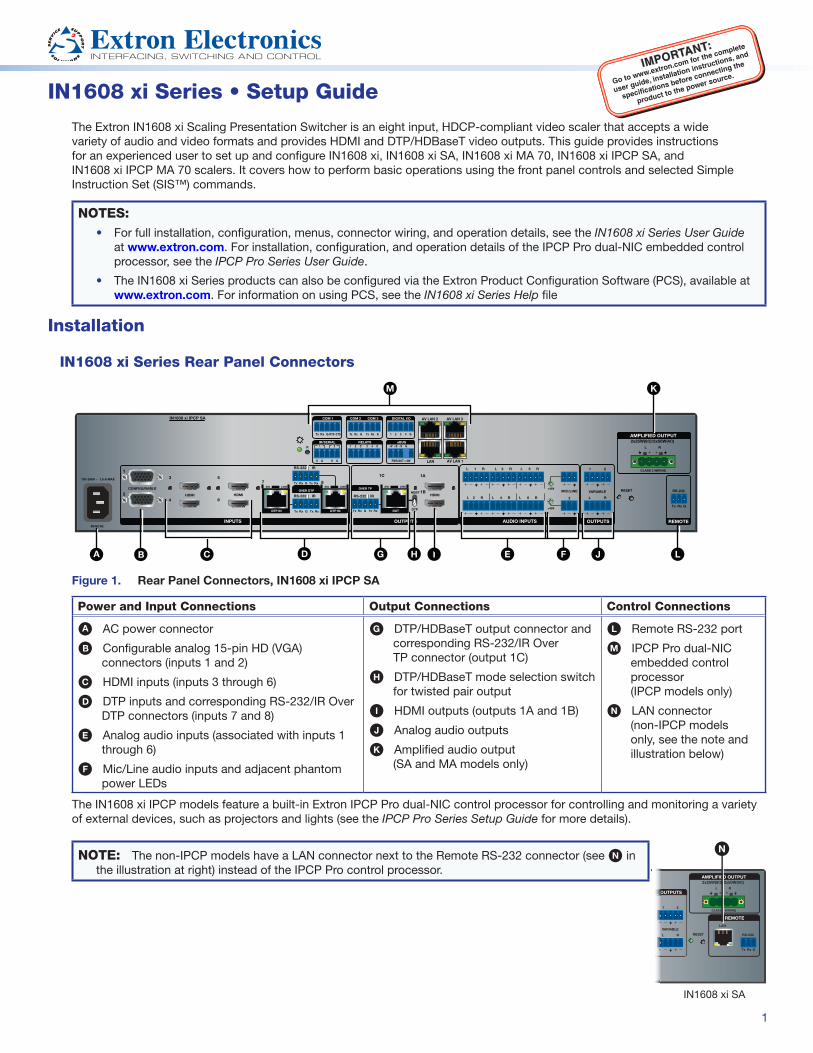
Figure 1. Rear Panel Connectors, IN1608 xi IPCP SA
Power and Input Connections Output Connections Control Connections
A AC power connector
B Configurable analog 15-pin HD (VGA) connectors (inputs 1 and 2)
C HDMI inputs (inputs 3 through 6)
D DTP inputs and corresponding RS-232/IR Over DTP connectors (inputs 7 and 8)
E Analog audio inputs (associated with inputs 1 through 6)
F Mic/Line audio inputs and adjacent phantom power LEDs
G DTP/HDBaseT output connector and corresponding RS-232/IR Over TP connector (output 1C)
H DTP/HDBaseT mode selection switch for twisted pair output
I HDMI outputs (outputs 1A and 1B)
J Analog audio outputs
K Amplified audio output (SA and MA models only)
L Remote RS-232 port
M IPCP Pro dual-NIC embedded control processor (IPCP models only)
N LAN connector (non-IPCP models only, see the note and illustration below)
The IN1608 xi IPCP models feature a built-in Extron IPCP Pro dual-NIC control processor for controlling and monitoring a variety of external devices, such as projectors and lights (see the IPCP Pro Series Setup Guide for more details).
NOTE: The non-IPCP models have a LAN connector next to the Remote RS-232 connector (see N in the illustration at right) instead of the IPCP Pro control processor.
Tx Rx
RS-232
G
LAN
2x25W(8Ω)/2x50W(4Ω)
RESET
OUTPUTS
REMOTE
L R
CLASS 2 WIRING1 2
L R
VARIABLE
AMPLIFIED OUTPUT
O
N
IN1608 xi SA

2
IN1608 xi • Setup Guide (Continued)
Mounting and Cabling
Step 1 — Mount the device
a. Turn off or disconnect all equipment power.
b. Mount IN1608 xi scaler to a rack using the pre-installed rack ears, or use an optional mounting kit for under-desk mounting (see the two images at right).
The IN1608 xi comes in a 1U, full rack width enclosure (shown in the examples at right). All other IN1608 xi models come in 2U, full rack width enclosures.
Step 2 — Connect inputs
a. Connect analog video sources to the VGA connectors (see figure 1, B, on the previous page).
b. Connect digital HDMI or DVI (with an appropriate adapter) sources to the HDMI connectors (C).
c. Connect a DTP transmitter to the DTP input connectors (D). For cable wiring and recommendations, see Twisted Pair Recommendations for DTP and HDBaseT Communication on the next page.
Signal LED — Lights green when the unit is receiving an active video signal from a DTP transmitter.
Link LED — Lights amber when a valid link is established to a DTP transmitter.
d. To pass serial or infrared data, connect the control device to the RS-232 and IR Over DTP captive screw connectors (see RS-232 and IR Over TP Wiring on the next page). Alternatively, insert RS-232 communication to a DTP/HDBaseT endpoint via Ethernet (see the IN1608 xi Series User Guide for more information).
e. Connect analog audio sources to the inputs via the 5-pole captive screw connectors (E). See Audio Wiring on the next page for more information.)
f. Connect Mic/Line audio sources to the inputs via the 3-pole captive screw connectors (F).
Step 3 — Connect outputs
a. Set the twisted pair switch (H) to one of the following positions:
• HDBT — Set the twisted pair switch to the Up position to set the twisted pair connector for HDBaseT communication. The switch returns to the middle position after.
• DTP — Set the twisted pair switch to the Down position to set the twisted pair connector for DTP communication.
b. Connect an DTP/HDBaseT-compatible device to the HDBT output connector (G). For cable wiring and recommendations, see Twisted Pair Recommendations for DTP and HDBaseT Communication.
Signal LED — Lights green when the scaler is outputting active video.
Link LED — Lights amber when a valid link is established between the scaler and the DTP/HDBaseT sink.
c. To pass serial or infrared data, connect a control device to the RS-232 and IR Over DTP captive screw connector (see RS-232 and IR Over TP Wiring on the next page). Alternatively, insert RS-232 communication to a DTP/HDBaseT endpoint via Ethernet (see the IN1608 xi Series User Guide for more information).
d. Connect suitable video displays to the HDMI connectors (I).
e. Connect analog audio devices to the outputs via the 3.5 mm, 5-pole captive screw connectors (J). See Audio Wiring on the next page for more information.
f. For SA and MA models, connect speakers to the Amplified Output via the 5 mm 4-pole or 2-pole captive screw connector (K).
Step 4 — Connect control devices
a. To control non-IPCP models through Ethernet, connect a LAN or WAN to the LAN connector (see N on page 1). For the IPCP models, connect a LAN or WAN to any of the LAN connectors on the IPCP Pro control processor (M). The default IP address of the scaler is 192.168.254.254. The default subnet mask is 255.255.255.0.
b. For serial RS-232 control, connect a host device to the 3-pole captive screw connector (L). The default baud rate is 9600.
c. For control through USB, connect a host device to the front panel USB mini-B port (see figure 2, A on page 4).
#8 Screw(4) PlacesEach Side MBU 149
Mounting Bracket
Mounting Screws(2) PlacesEach Side
Furniture Mounting
Rack Ears
Rack Mounting

3
Step 5 — Set up the IPCP Pro 355 control processor (IPCP models only)
See the IPCP Pro Series Setup Guide, available at www.extron.com, for installation details.
Step 6 — Connect power
Connect a 100 to 240 VAC, 50-60 Hz power source to the AC power connector (see figure 1, A, on page 1).
Twisted Pair Recommendations for DTP and HDBaseT Communication
Extron recommends using the following practices to achieve full transmission distances and reduce transmission errors:
• Use Extron XTP DTP 24 SF/UTP cable for the best performance. At a minimum, Extron recommends 24 AWG, solid conductor, STP cable with a minimum bandwidth of 400 MHz.
• Terminate cables with shielded connectors to the TIA/EIA-T568B standard (shown at right).
• Limit the use of more than two pass-through points, which may include patch points, punch down connectors, couplers, and power injectors. If these pass-through points are required, use shielded couplers and punch down connectors.
ATTENTION:
• Do not connect these connectors to a computer or telecommunications network.
• Ne connectez pas ces ports à des données informatiques ou à un réseau de télécommunications.
• DTP remote power is intended for indoor use only. No part of the network that uses DTP remote power should be routed outdoors.
• L’alimentation DTP à distance est destiné à une utilisation en intérieur seulement. Aucune partie du réseau qui utilise l’alimentation DTP à distance ne peut être routée en extérieur.
NOTE: When using shielded twisted pair cable in bundles or conduits, consider the following:
• Do not exceed 40% fill capacity in conduits.
• Do not comb the cable for the first 20 meters, where cables are straightened, aligned, and secured in tight bundles.
• Loosely place cables and limit the use of tie wraps or hook-and-loop fasteners.
• Separate twisted pair cables from AC power cables.
RS-232 and IR Over TP WiringTo pass bidirectional serial command signals between DTP or HDBaseT-compatible devices, connect a control device to the three leftmost poles (Tx, Rx, and G) of the 5-pole captive screw connector. To transmit and receive IR signals, connect a control device to the three rightmost poles (G, Tx, and Rx).
NOTE: Alternatively, RS-232 data can be inserted via Ethernet (see the IN1608 xi Series User Guide for details).
Audio WiringWire the audio input and output connectors as shown at right. Use the supplied tie wrap to strap the audio cable to the extended tail of the connector. This does not apply to the amplified audio output connector on the SA and MA models.
ATTENTION: For unbalanced outputs, do not connect wires to the “-” poles (see the Extron Audio Wiring Card).
ATTENTION : Pour les sorties asymétriques, ne connectez pas de câbles aux pôles « - » (voir le Audio Wiring Card d’Extron).
NOTE: The length of exposed wires is critical. The ideal length is 3/16 inch (5 mm).
Balanced Audio Output
TipRing
TipRing
Sleeves
Unbalanced Audio Output
Tip
No Ground Here
No Ground Here
TipSleeves
LR
LR
Unbalanced Audio InputBalanced Audio Input
Tip
Ring
TipRing
SleevesTip
Sleeve
SleeveTip
LR
LR
Do not tin the wires!
TIA/EIA-T568B
Pin Wire Color
1 White-orange
2 Orange
3 White-green
4 Blue
5 White-blue
6 Green
7 White-brown
8 Brown
12345678
RJ-45Connector
Insert TwistedPair Wires
Pins:
Pin
1
2
3
4
5
6
7
8
Wire color
White-green
Green
White-orange
Blue
White-blue
Orange
White-brown
Brown
Wire colorT568A T568B
White-orange
Orange
White-green
Blue
White-blue
Green
White-brown
Brown

4
Front Panel Overview
VOLUME
SCALING PRESENTATION SWITCHER
IN1608 xi
INPUTS
1
HDCP
SIGNAL
OUTPUTS
ENTER
MENU
E
2 3 4 5 6 7 8 1A 1B 1C
CONFIG
1 2 3 4 5 6 7 8INPUTS
eBUS
OVER
LIMITSTx
Rx
RTS
1 2
1
3
1
4
2
3
1
4
2CTS
2 3
COM
IR/S I/O RELAYS
A B C D E F
G
Figure 2. Front Panel Features, IN1608 xi IPCP SA
A Front panel configuration port — Connect a host device to the USB mini-B port for device configuration, control, and firmware upgrades.
B Input selection buttons (1-8) — Press one of these buttons to select an input. The buttons light amber for audio and video, green for video only, or red for audio only.
C Status LED indicators
• Input signal LEDs — Light green for each input when active video content is detected.
• Output signal LEDs — Remain lit green when active video is being output or blink amber when output video and sync are disabled.
• Input HDCP LEDs — Light green for each input signal that is HDCP-encrypted. Analog inputs 1 and 2 cannot be HDCP-encrypted.
• Output HDCP LEDs — Light green for an output when it is currently HDCP-encrypted.
D Menu and Enter buttons — Press these buttons to access and navigate the on-screen display menu system.
E Navigation buttons — Press these buttons to navigate through the on-screen display menu system or change selected settings.
F Volume knob and LED indicators — Rotate the Volume knob to adjust the program, microphone, or output volume. The eight Volume LED indicators light according to the volume level. The LEDs light in order from bottom to top to indicate steps from 1% (-99 dB) to 99% (-1 dB). The bottom LED blinks when the volume is muted. The top LED blinks when the volume is at 100% (0 dB).
G IPCP Pro LED indicators — IPCP Pro models only (see the IPCP Pro Series Setup Guide for details).
IN1608 xi Series ConfigurationTo configure IN1608 xi scalers, use the front panel controls and the on-screen display (OSD) menu, the internal web pages, PCS, or SIS commands.
On-screen Display (OSD) Menu SystemTo configure IN1608 xi scalers using the OSD menu, connect a display to either HDMI output or to a DTP/HDBaseT device. The OSD menu consists of nine submenus accessed using the front panel Menu or Enter button (see the example above, right).
NOTE: Press and hold the Enter button for 10 seconds to edit settings in the Communication submenu.
Internal Web PagesTo configure IN1608 xi scalers using the factory-installed web pages in a web browser (see the example at right), connect the Ethernet port on the device to a LAN or WAN. The default IP address is 192.168.254.254.

5
Extron Product Configuration SoftwareTo configure IN1608 xi scalers using PCS, install the software (available on the Extron website, www.extron.com) to a PC connected to the scaler via Ethernet or front panel USB Config port. After the installation, start the program. For full instructions, press <F1> on the keyboard or click the ? button in the software and select Help File.
Basic SIS Command TableTo configure IN1608 xi scalers with specific SIS commands via an RS-232, USB, or Ethernet connection, use the Extron DataViewer utility or a control system to send and receive SIS commands. The table below lists a selection of SIS commands. For a full list of SIS commands and variables, see the IN1608 xi Series User Guide at www.extron.com.
Command ASCII Command Response Additional Description
Select audio and video input X!! InX!•All] Selects audio and video input X!.
Select video input only X!& InX!•RGB] Selects the video only input X!.
Select audio input only X!$ InX!•Aud] Selects the audio only input X!.
Execute Auto-Image™ A Img0] Executes an Auto-Image on the current input.
Execute Auto-Image and fill 1*A Img1] Executes an Auto-Image and fills the output.
Execute Auto-Image and follow 2*A Img2] Executes an Auto-Image and maintains the aspect ratio of the current input.
Mute video to black 1B Vmt1] Mutes the video and displays a black output.
Mute video and sync 2B Vmt2] Mutes the video and sync output.
Unmute video and sync 0B Vmt0] Unmutes the video.
NOTE: By default, setting the audio mute with the following commands affects all outputs (configurable through group masters).
Set master audio mute ED7*X(GRPM GrpmD07*X(] Enable or disable master audio mute.
View master audio mute status ED7GRPM X(] View the current master audio mute status.
Enable executive mode 1 1X Exe1] Locks the entire front panel.
Enable executive mode 2 2X Exe2] Locks the front panel except for input selection and volume control.
Disable executive modes 0X Exe0] Allows all front panel adjustments and selections.
Set scaler IP address EX4)CI Ipi•X4)] Specifies a new scaler IP address.
Set scaler DHCP mode EX(DH IdhX(] Enables or disables DHCP (0 = default).
Set subnet mask EX4!CS Ips•X4!] Specifies a new subnet mask.
Set gateway IP address EX4@CG Ipg•X4@] Specifies a new gateway IP address.
Reboot network E2BOOT Boot2] Restarts the network connection after IP or DHCP changes.
NOTE: IP settings do not take effect until the E2BOOT command is executed.
View DTP vs. HDBT Switch Position
EO3HDBT X6&]HdbtO3*X6&]
View the DTP/HDBT mode switch position X6& on output 1C (verbose mode 2/3 response).
NOTES: X! = Input selection (1-8) X( = Enable or disable: 0 = off or disabled, 1 = on or enabled) X4) = IP address (nnn.nnn.nnn.nnn), 192.168.254.254 = default) X4! = Subnet mask (nnn.nnn.nnn.nnn), 255.255.255.0 = default) X4@ = Gateway address (nnn.nnn.nnn.nnn), 0.0.0.0 = default) X6& = TP format: 0 = DTP format (default), 1 = HDBaseT format
Firmware Updates
Download firmware updates from the Extron website and upload them via the internal web pages, PCS, or the Extron Firmware Loader program.

668-1916-53 Rev. A
11 17
Copyright© 2017 Extron Electronics. All rights reserved.
TrademarksAll trademarks mentioned in this guide are the properties of their respective owners.The following registered trademarks(®), registered service marks(SM), and trademarks(TM) are the property of RGB Systems, Inc. or Extron Electronics (see the current list of trademarks on the Terms of Use page at www.extron.com):
Registered Trademarks (®)
Extron, Cable Cubby, ControlScript, CrossPoint, DTP, eBUS, EDID Manager, EDID Minder, Flat Field, FlexOS, Global Configurator, Global Scripter, GlobalViewer, Hideaway, HyperLane, IP Intercom, IP Link, Key Minder, LinkLicense, LockIt, MediaLink, MediaPort, NetPA, PlenumVault, PoleVault, PowerCage, PURE3, Quantum, SoundField, SpeedMount, SpeedSwitch, System INTEGRATOR, TeamWork, TouchLink, V-Lock, VideoLounge, VN-Matrix, VoiceLift, WallVault, WindoWall, XTP, XTP Systems, and ZipClip
Registered Service Mark(SM) : S3 Service Support Solutions
Trademarks (™)
AAP, AFL (Accu-Rate Frame Lock), ADSP (Advanced Digital Sync Processing), Auto-Image, CableCover, CDRS (Class D Ripple Suppression), Codec Connect, DDSP (Digital Display Sync Processing), DMI (Dynamic Motion Interpolation), Driver Configurator, DSP Configurator, DSVP (Digital Sync Validation Processing), eLink, Entwine, EQIP, Everlast, FastBite, FOX, FOXBOX, IP Intercom HelpDesk, MAAP, MicroDigital, Opti-Torque, ProDSP, QS-FPC (QuickSwitch Front Panel Controller), Room Agent, Scope-Trigger, ShareLink, Show Me, SIS, Simple Instruction Set, Skew-Free, SpeedNav, StudioStation, Triple-Action Switching, True4K, Vector™ 4K , WebShare, XTRA, and ZipCaddy
Extron Headquarters+800.633.9876 Inside USA/Canada Only
Extron USA - West Extron USA - East+1.714.491.1500 +1.919.850.1000
+1.714.491.1517 FAX +1.919.850.1001 FAX
Extron Europe+800.3987.6673
Inside Europe Only
+31.33.453.4040
+31.33.453.4050 FAX
Extron Asia+65.6383.4400
+65.6383.4664 FAX
Extron Japan+81.3.3511.7655
+81.3.3511.7656 FAX
Extron China+86.21.3760.1568
+86.21.3760.1566 FAX
Extron Middle East+971.4.299.1800
+971.4.299.1880 FAX
Extron Australia+61.8.8113.6800+61.8.8351.2511 FAX
Extron India1800.3070.3777
(Inside India Only)
+91.80.3055.3777
+91.80.3055.3737 FAX
© 2017 Extron Electronics All rights reserved. All trademarks mentioned are the property of their respective owners. www.extron.com