extron mediaport 200 audio application...
TRANSCRIPT

User Guide
MediaPort 200Audio Application Tutorial
USB Switchers and Bridges
68-2755-02 Rev. A 12 15

Conventions Used in this Guide
NotificationsThe following notifications are used in this guide:
NOTE: A note draws attention to important information.
Extron Glossary of TermsA glossary of terms is available at http://www.extron.com/technology/glossary.aspx.
Copyright© 2015 Extron Electronics. All rights reserved.
TrademarksAll trademarks mentioned in this guide are the properties of their respective owners.
The following registered trademarks®, registered service marks(SM), and trademarks(TM) are the property of RGB Systems, Inc. or Extron Electronics:
Registered Trademarks (®)
Extron, AVTrac, Cable Cubby, CrossPoint, DTP, eBUS, EDID Manager, EDID Minder, Flat Field, FlexOS, Global Configurator, GlobalViewer, Hideaway, Inline, IP Intercom, IP Link, Key Minder, LinkLicense, LockIt, MediaLink, NetPA, PlenumVault, PoleVault, PowerCage, PURE3, Quantum, SoundField, SpeedMount, SpeedSwitch, System INTEGRATOR, TeamWork, TouchLink, V‑Lock, VersaTools, VN‑Matrix, VoiceLift, WallVault, WindoWall, XTP, and XTP Systems
Registered Service Mark (SM) : S3 Service Support Solutions
Trademarks (™)
AAP, AFL (Accu‑Rate Frame Lock), ADSP (Advanced Digital Sync Processing), Auto‑Image, CableCover, CDRS (Class D Ripple Suppression), DDSP (Digital Display Sync Processing), DMI (Dynamic Motion Interpolation), Driver Configurator, DSP Configurator, DSVP (Digital Sync Validation Processing), eLink, EQIP, FastBite, FOX, FOXBOX, IP Intercom HelpDesk, MAAP, MicroDigital, ProDSP, QS‑FPC (QuickSwitch Front Panel Controller), Room Agent, Scope‑Trigger, ShareLink, SIS, Simple Instruction Set, Skew‑Free, SpeedNav, Triple‑Action Switching, True4K, Vector™ 4K, WebShare, XTRA, ZipCaddy, ZipClip

iiiMediaPort 200 Audio Application Tutorial • Contents
Contents
Audio Application Setup ............................1Overview ............................................................. 1
Line Inputs ....................................................... 1USB Communications Input............................. 2Mic Input ......................................................... 2Line Output...................................................... 3Ref/Aux Out ..................................................... 3
Application Setup Examples ................................ 4Application 1 – Standalone MediaPort 200 ...... 4Application 2 – MediaPort 200 with DSP Processor with AEC ........................................ 5
Application 3 – MediaPort 200 with Hardware and Software Codecs ..................................... 7
Application 4 – MediaPort 200 with Hardware and Software Codecs and DSP Processor ..... 8
Using the Mix Tab .............................................. 10Set Room Volume .......................................... 10Set Mix to Far End ......................................... 10
Mix Tab Details .................................................. 11Program Mix .................................................. 11From Far End ................................................. 11Near End ....................................................... 12Mix to Far End ............................................... 12
MediaPort 200 Signal Flow ......................13Matrix Routing ................................................... 13Mixing and Control ............................................ 15
Program and Far End Mix .............................. 15Master Volume Controls ................................. 17Room Volume (Near End) ............................... 18Mix to Far End ............................................... 20AEC Ref and Aux Outs .................................. 21
Configurations for DMP 128 ....................22Routing for Application #2 ................................. 22
Mic Inputs 1 – 8 ............................................. 22Program L/R Inputs 9 and 10 ........................ 22USB Communications Input 11...................... 23
Routing for Application #4 ................................. 24Mic Inputs 1 – 8 ............................................. 24Program L/R Inputs 9 and 10 ........................ 24USB Communications Input 11...................... 24Video Codec Input 12 ................................... 25
Control – Application #2 .................................... 26Program — Master Volume ............................ 26Program — Master Mute ............................... 26Far End — Master Volume ............................. 26Far End — Master Mute ................................ 26Privacy Mute — Master Mute......................... 26Group Masters............................................... 27
Control – Application #4 .................................... 28Program — Master Volume ............................ 28Program — Master Mute ............................... 28Far End — Master Volume ............................. 28Far End — Master Mute ................................ 28Video Codec — Master Volume ..................... 28Video Codec — Master Mute ........................ 28Privacy Mute — Master Mute......................... 29Group Masters............................................... 29
Gain and DSP Processing ................................. 30Input Signal Chain (Microphones) ................... 30Input Signal Chain (Line Level Devices) .......... 31Output Signal Chain ....................................... 31

MediaPort 200 Audio Application Tutorial • Contents iv
Gain Structure .........................................32MediaPort 200 ................................................... 32
Input tab ........................................................ 32Mix tab .......................................................... 32Output tab ..................................................... 33
External Processors ........................................... 34Peak Meters in dBFS ..................................... 34Peak Meters in dBu ....................................... 34RMS Meters in dBu ....................................... 34
Sound Reinforcement System ........................... 34

MediaPort 200 Audio Application Tutorial • Audio Application Setup 1
Audio Application Setup
The MediaPort 200 is designed to integrate seamlessly into a variety of applications. This section contains tutorials for how to set up the MediaPort 200 in the following applications:
• Application 1 – MediaPort 200 (standalone)
• Application 2 – MediaPort 200 + DSP matrix processor with AEC
• Application 3 – MediaPort 200 + hardware video codec
• Application 4 – MediaPort 200 + DSP matrix processor with AEC + hardware video codec
In applications 2 and 4, specific inputs or outputs are defined for use with the Extron DMP 128 C models as the external DSP matrix processor (herein referred to as “DSP processor”). DSP Configurator template files with the routing and configurations described are available for use with all DMP 128 C models, and can be downloaded from the Extron website. These pre‑configured files facilitate and greatly simplify the integration of the MediaPort 200 with Extron DMP 128 C model products. See section, Configurations for DMP 128 on page 22 for more information on using the DSP Configurator template files.
OverviewThis section contains a general discussion on MediaPort inputs and outputs and their intended uses. All of the principals described in this section are put into practice in the application setup tutorials that follow.
Line InputsThe following MediaPort 200 line inputs are typically used for program audio:
• USB Playback — The MediaPort is the computer USB audio playback device.
• HDMI — Accepts 2‑channel PCM signals from this digital connection.
• Line Input (Analog) — Accepts balanced or unbalanced line level signals.
USB Playback Input
The local PC may be used as a program source via the USB connection. This is independent of the far end USB Communication audio sent from the computer to the MediaPort 200.

MediaPort 200 Audio Application Tutorial • Audio Application Setup 2
HDMI Input
The HDMI input may be fed from a camera, a computer, or from a switcher or other HDMI source. The loop out may be connected to a local display, or to a hardware codec in applications that utilize a hardware codec (such as Applications #3 and #4). The HDMI source may be a video conference or document camera without audio, or may be another program source such as a PC or switcher output that includes embedded audio. If the HDMI input is used with a camera that includes microphone audio, the HDMI audio input should be muted.
The HDMI input may alternatively be connected to a matrix switcher. In this case, the loop out may be used to connect to a hardware codec. For additional flexibility, an output from the matrix switcher may be connected to the hardware codec. Connecting an output from the matrix switcher to the hardware codec allows for different content to be sent to software codec and the hardware codec, as needed.
Line Input (Analog)
Connect an analog program source to the line input. This could be the output of a switcher, or an auxiliary program source such as a CD/DVD player, mobile device, media player, etc.
These line inputs are mixed to the USB output and sent to the far end, and are also sent to the analog line output. The analog line output path also mixes in the USB Communications audio (from the far end), while USB audio output path does not. See section, MediaPort 200 Signal Flow on page 13 for more information.
USB Communications InputUSB “Communications,” or far end audio, is mixed with the line inputs to the analog line output for local sound reinforcement. It is also summed and sent by itself to the AEC Ref Out. When the MediaPort 200 is used with a DSP processor, USB far end audio should be muted to the line output, and received at the DSP processor from the MediaPort Ref Out instead.
Mic InputThe mic input may be connected to a dynamic or condenser microphone that will serve as the conferencing mic. Alternatively, a mic mixer—generally, a DSP processor with AEC—may be connected to the mic input. The mic input is sent to the USB output to the computer to be sent to the far end of a soft codec conference, but not to the line outputs. The mic input is also sent to the Aux Output and can be connected to a hardware codec for the application of soft codec + hardware codec conferencing (Application #3), or to a sound reinforcement “voicelift” system if needed.

MediaPort 200 Audio Application Tutorial • Audio Application Setup 3
Line OutputThe line output is used to connect to a local sound reinforcement system. All line input program sources, plus the USB Communications audio from the far end, are mixed to the line output. In an application that uses a DSP processor in conjunction with the MediaPort 200, the analog line output will be connected to the DSP processor as an AEC reference for the program material, and then sent to local sound reinforcement from the DSP processor. In this case, USB communications audio (far end) will be muted to the line output and sent to the DSP processor via the AEC reference output (see section, Using the Mix Tab on page 10 for more information).
USB Communications audio from the far end is always routed to the AEC Out. This is intended for use with a DSP processor, so that far end USB Communications audio can be used as an AEC reference in the DSP, and then sent to the local sound reinforcement system from the DSP processor. When USB Communications audio is muted to the line output, the line output will send only program audio to the DSP processor. This allows program audio to be managed separately from USB Communications audio. Program audio may also be used as an AEC reference, and either mixed to the same sound system as USB Communications audio or sent to a separate sound system.
Ref/Aux OutThe AEC “Ref” output is used in conjunction with a DSP processor using multiple microphones with distributed AEC (i.e., an AEC processor on every microphone channel). Only USB far end audio is routed directly to the AEC reference output. Alternatively, the AEC output can be used to send USB Communications audio to a separate sound system from program audio mixed to the line output. In this case, USB Communications audio would be muted to the line output.
The Aux Out contains only the mic input signal from the MediaPort 200. This facilitates connecting both the MediaPort 200 and a hardware codec when the same mic applied to the MediaPort 200 is to be simultaneously used as the mic source for the hardware codec.

MediaPort 200 Audio Application Tutorial • Audio Application Setup 4
Application Setup Examples
Application 1 – Standalone MediaPort 200This is an application for soft codec conferencing, where the MediaPort 200 operates as a standalone device.
Med
iaP
ort
200
100-240V - - A MAX
50/60 Hz
HDMI
LOOP OUT
MIC/LINE
+48V
LINEL R LINEL R
REMOTEOUTPUT
LANUSB
REF AUX
RESETRS-232 +12V
I/O
Tx
0.1AMAX
Rx �
I1 I2 � O 1 O2
INPUT
iPod 9:45 AM
•P HUS
•
POWER STANDBY
Table Microphone
iPodCamera
PC
Audio
Video/AudioMediaPort 200
XPA 1002XPA 1002
1 2
LIMITER/PROTECT
SIGNAL
OVERTEMP
'
Figure 1. Application 1 — Standalone MediaPort 200 for Soft Codec Conferencing
1. Connect an HDMI source to the MediaPort input. For this example, an HDMI video camera is used.
2. Connect a program source to the MediaPort Line Input (as needed).
3. Connect a microphone to the MediaPort Mic Input.
4. Connect the MediaPort Line Output to a sound reinforcement system.
5. Connect a USB cable to the MediaPort rear panel USB connector and your PC or Mac computer. Make sure that the drivers are configured.
6. Set the MediaPort 200 to enumerate as a Speakerphone device.

MediaPort 200 Audio Application Tutorial • Audio Application Setup 5
Application 2 – MediaPort 200 with DSP Processor with AECThis is an application for soft codec conferencing, where the MediaPort 200 operates in conjunction with a DSP processing device with AEC (acoustic echo cancellation). The MediaPort AEC Ref output sends far end USB communications audio to the DSP processor as an AEC reference. The line output from the MediaPort 200 sends program audio to the DSP processor, where it’s routed for AEC reference and for sound reinforcement. The send to the sound reinforcement system, which includes program and far end audio, comes from the DSP processor output.
Med
iaP
ort
200
100-240V - - A MAX
50/60 Hz
HDMI
LOOP OUT
MIC/LINE
+48V
LINEL R LINEL R
REMOTEOUTPUT
LANUSB
REF AUX
RESETRS-232 +12V
I/O
Tx
0.1AMAX
Rx G
I1 I2 G O1 O2
INPUT
100-240V ~ 0.7A MAX
50/60 Hz LANEXP
RS-232
Tx Rx G
RESET
MIC +48V
5 6 7 8
1 2 3 4 8
4 1
1 2 3 4 5 G 61 2 3 4
7 8 9 10 G
11 12 13 14 15 G 16 17 18 19 20 G
2 3 4
5 6 7 8
9 10
11 127
3
6
2
5
1
MIC
/LIN
E IN
PU
TS
OU
TP
UT
S
DIG
ITA
L I/
O
RE
MO
TE
AT
DMP 128 C AT
DMP 128 C AT
iPod 9:45 AM
XPA 1002XPA 1002
1 2
LIMITER/PROTECT
SIGNAL
OVERTEMP
•PHU
S• •P
HUS
• •PHU
S• •P
HUS
• •PHU
S•
POWER STANDBY
Table Microphones
iPodHD Camera
Audio
Video/AudioMediaPort 200
PC
Figure 2. Application 2 — MediaPort 200 with a DMP 128 DSP Processor for Soft Codec
For this application the MediaPort must be configured for use with an external AEC processing device. In Extron PCS, navigate to the General Settings page, and under Audio Mode, select External DSP with AEC.
Connect to the MediaPort 200
1. Connect an HDMI source to the MediaPort input. For this example, an HDMI video camera is used.
2. Connect a program source to the MediaPort Line Input (as needed).
3. Connect a USB cable to the MediaPort rear panel USB connector and your PC or Mac computer. Make sure that the drivers are configured properly.
4. Set the MediaPort 200 to enumerate as a Speakerphone device with AEC.

MediaPort 200 Audio Application Tutorial • Audio Application Setup 6
Connect MediaPort 200 to the DSP matrix processor
1. Connect the line output of the MediaPort 200 to line inputs on the DSP processor [DMP 128 Input 9 (“MP Program L”) and Input 10 (“MP Program R”)].
The MediaPort line output sends the program mix signal to the DSP processor. In this application, select the “AEC Ref Only” radio button for USB Communications audio, located on the Mix tab in PCS. This signal is used in the DSP processor as an AEC reference on each microphone input, and also routed to the sound reinforcement system from the DSP processor.
2. Connect the AEC Ref output of the MediaPort 200 to a line input on the DSP processor [DMP 128 Input 11 (“MP Far End”)].
The AEC Ref output sends the USB Communications signal (far end audio) from the MediaPort to the DSP processor. This signal is used in the DSP processor as an AEC reference on each microphone input, and also routed to the sound reinforcement system from the DSP processor.
3. Connect a line output on the DSP processor to the mic input of the MediaPort 200 [DMP 128 Output 3 (“To MP Mic In”)].
This line output sends a mix of the microphones connected to the DSP processor.
Connect from the DSP processor
1. Connect line outputs on the DSP processor to the local sound reinforcement system [DMP 128 Output 1 (“SP Spkr L”) and Output 2 (“SP Spkr R”)].
This line output will contain a mix of the local program material routed from the MediaPort Line Out plus the USB Communications audio that had been routed to the DSP processor from the MediaPort AEC Ref Out.
Connect to the DSP processor
1. Connect up to eight microphones to DMP 128 Inputs 1 – 8. Once the microphone types are selected, Extron Building Blocks can be used to configure the mic channels for gain and processor settings (see the DMP 128 User Guide or DSP Configurator Help File for information about Building Blocks).

MediaPort 200 Audio Application Tutorial • Audio Application Setup 7
Application 3 – MediaPort 200 with Hardware and Software CodecsThis is an application for soft codec conferencing in a room that also has a hardware video codec. Either may be used independently at any time. This application uses the single microphone input on the MediaPort 200 for both conferencing devices.
Med
iaP
ort
200
100-240V - - A MAX
50/60 Hz
HDMI
LOOP OUT
MIC/LINE
+48V
LINEL R LINEL R
REMOTEOUTPUT
LANUSB
REF AUX
RESETRS-232 +12V
I/O
Tx
0.1AMAX
Rx �
I1 I2 � O 1 O2
INPUT
•P HUS
•
POWER STANDBY
Table Microphone
Video Codec
Camera
PC
Display
Audio
Video/AudioMediaPort 200
XPA 1002XPA 1002
1 2
LIMITER/PROTECT
SIGNAL
OVERTEMP
HDMI DA
'
Figure 3. Application 3 — MediaPort 200 with Hardware and Software Codecs
Connect to and from the MediaPort 200
1. Connect an HDMI source to the MediaPort input. For this example, an HDMI video camera is used.
2. Connect the HDMI loop out on MediaPort to the camera or content input on the hardware video codec. If a matrix switcher is being used an output of the switcher, it may alternatively be connected to the hardware video codec.
3. Connect the MediaPort Line Output to a sound reinforcement system.
4. Connect a microphone to the Mic Input.
5. Connect a USB cable to the rear USB connector and your PC or Mac computer. Make sure that the drivers are configured properly.
6. Set the MediaPort 200 to enumerate as a Speakerphone device.

MediaPort 200 Audio Application Tutorial • Audio Application Setup 8
Connect MediaPort to/from the hardware video codec
1. Connect the Aux Out of the MediaPort to the input of the video codec. This may be the microphone input of the video codec, although preferably it should be able to receive a line level signal. Check the user guide of the video codec to find the appropriate input and settings.
The MediaPort Aux Out sends the microphone signal to the video codec. Doing so allows the same microphone to be used with the MediaPort only, the video codec only, or both simultaneously.
2. Connect the line output of the video codec to the MediaPort line input. This will route the hardware codec audio to the sound reinforcement system in the room, and also to the far end of the soft codec conference in the case where hardware and software conferences are bridged.
Application 4 – MediaPort 200 with Hardware and Software Codecs and DSP Processor
This is an application for soft codec conferencing in a room that also has a hardware video codec, in addition to a DSP processor that adds multiple microphones with distributed AEC. Either software or hardware conferencing may be used independently at any time, or both may be used simultaneously bridging both hardware and software codecs into the same conference.
Med
iaP
ort
200
100-240V - - A MAX
50/60 Hz
HDMI
LOOP OUT
MIC/LINE
+48V
LINEL R LINEL R
REMOTEOUTPUT
LANUSB
REF AUX
RESETRS-232 +12V
I/O
Tx
0.1AMAX
Rx G
I1 I2 G O1 O2
INPUT
100-240V ~ 0.7A MAX
50/60 Hz LANEXP
RS-232
Tx Rx G
RESET
MIC +48V
5 6 7 8
1 2 3 4 8
4 1
1 2 3 4 5 G 61 2 3 4
7 8 9 10 G
11 12 13 14 15 G 16 17 18 19 20 G
2 3 4
5 6 7 8
9 10
11 127
3
6
2
5
1
MIC
/LIN
E IN
PU
TS
OU
TP
UT
S
DIG
ITA
L I/
O
RE
MO
TE
AT
DMP 128 C AT
DMP 128 C AT
XPA 1002XPA 1002
1 2
LIMITER/PROTECT
SIGNAL
OVERTEMP
•PHU
S• •P
HUS
• •PHU
S• •P
HUS
• •PHU
S•
POWER STANDBY
Table Microphones
HD Camera
Audio
Video/AudioMediaPort 200
PC
Video Codec
Display
HDMI DA
iPod 9:45 AM
iPod
Figure 4. Application 4 — MediaPort 200 with Hardware and Software Codecs and a DSP Processor
For this application, the MediaPort must be configured for use with an external AEC processing device. In Extron PCS, navigate to the General Settings page, and under Audio Mode, select External DSP with AEC.

MediaPort 200 Audio Application Tutorial • Audio Application Setup 9
Connect to the MediaPort 200
1. Connect an HDMI source to the MediaPort input. For this example, an HDMI video camera is used.
2. Connect the HDMI loop out on MediaPort to the camera input or content input on the hardware video codec.
3. Connect a program source to the MediaPort Line Input (as needed).
4. Connect a USB cable to the MediaPort rear panel USB connector and your PC or Mac computer. Make sure that the drivers are configured properly.
5. Set the MediaPort 200 to enumerate as a Speakerphone device with AEC.
Connect MediaPort to the DSP matrix processor
1. Connect the line output of the MediaPort 200 to line inputs on the DSP processor [DMP 128 Input 9 (“MP Program L”) and Input 10 (“MP Program R”)].
2. Connect the AEC Ref output of the MediaPort 200 to a line input on the DSP processor [DMP 128 Input 11 (“MP Far End”)].
The AEC Ref output sends the USB Communications signal (far end audio) from the MediaPort to the DSP processor. This signal is used in the DSP processor as an AEC reference on each microphone input, and also routed to the sound reinforcement system from the DSP processor.
3. Connect a line output on the DSP processor to the mic input of the MediaPort 200 [DMP 128 Output 3 (“To MP Mic In”)].
This line output sends a mix of the microphones connected to the DSP processor to the MediaPort.
Connect the video codec to the DSP processor:
1. Connect a line output on the DSP processor (DMP 128 output 4) to the input of the video codec. This may be the microphone input of the video codec, although preferably it should be able to receive a line level signal. Check the user guide of the video codec to find the appropriate input and settings. This line output also sends a mix of the microphones connected to the DSP processor to the video codec.
2. Connect the mono line output of the video codec to line inputs on the DSP processor [DMP 128 Input 12 (“Video Codec”)].
Connect from the DSP processor:
1. Connect line outputs on the DSP processor to the local sound reinforcement system. (DMP 128 outputs 1 & 2.)
This line output will contain a mix of the local program material routed from the MediaPort Line Out plus the USB Communications audio that had been routed to the DSP processor from the MediaPort AEC Ref out.
Connect to the DSP processor:
1. Connect up to eight microphones to DMP 128 Inputs 1 – 8. Once the microphone types are selected, Extron Building Blocks can be used to configure the mic channels for gain and processor settings (see the DMP 128 User Guide or DSP Configurator Help File for information about Building Blocks).

MediaPort 200 Audio Application Tutorial • Audio Application Setup 10
Using the Mix TabNavigate to the Mix tab in PCS. Once the MediaPort 200 inputs are set up for optimal levels, and the outputs are set according to the signal level needed at the receiving devices (such as amplifiers, DSP processor, and video codecs), MediaPort 200 mix and listening levels may be controlled from the Mix tab.
Figure 5. PCS Mix Tab
Set Room VolumeSet the Room Volume master (2) in the Near End section of the Mix tab to −20dB. This is a safe level to start playback. One by one, play your program sources. Switch between them and set the individual levels of the line input sources with the faders in the Program Mix section 1 so that each program source plays back at about the same level. Next, adjust the Room Volume master fader to a comfortable listening level for the room. A final setting of −10 for the Program master leaves a bit of “headroom” if room volume needs to be increased (this will depend very much on the size of the amplifier in the room and its input sensitivity setting).
The USB Communications fader has an additional setting, AEC Ref Only, which will mute the USB communications or “far end” audio to the line output, while continuing to route this audio to the AEC Ref output. When using a DSP processor for microphones and AEC, the AEC Ref Only option should be selected. Doing so isolates the USB far end audio from the program audio, so that they can be handled independently in the DSP processor.
Set Mix to Far EndAdjustments to the Mix to Far End section of the Mix tab are made during a soft codec conference. The Mic and Program faders create the mix of program and mic audio that is sent to the far end over the USB output. They can be used if the conference participants at the far end comment that one is louder than the other, for instance. Adjust the Mic master (3) and Program master (4) in the Mix to Far End section to achieve a proper blend of mic and program material, providing clear, undistorted audio. Set this mix level while the talkers at the near end and far end are speaking at a normal levels for conferencing, and when program material is being played at the far end.

MediaPort 200 Audio Application Tutorial • Audio Application Setup 11
Mix Tab DetailsThis section provides a more detailed description of the Mix tab controls and the signal flow being affected. The Mix tab is divided into four sections:
• Program Mix
• From Far End
• Near End
• Mix to Far End
Program MixThe line inputs that typically carry program material are the USB Playback, HDMI, and analog Line Input. There is a gain point in the Input tab for setting input gain for each input. There are additional gain points that are post‑input gain, which are used for setting Program Mix. The program mix set in this section of the Mix tab is sent to the Line Output, and also to the USB Out. By setting the program mix levels at the post‑input gain point, the same mix will be sent to both outputs.
The mix of line input sources made in the Program Mix section is also sent to the Far End, with the exception that the Level to Far End Program mix does not include far end communications audio from the computer. The Room Volume master and the Mix to Far End master faders are independent of each other. Adjusting the Room Volume will not affect the level sent to the Far End, but adjusting the individual program faders will affect the mix going to both the room and the far end.
From Far EndThe USB Communications input receives the far end audio signal from the soft codec conference. This audio is then sent to the MediaPort analog line output, so that it can be heard in the near end room through the sound reinforcement system. The USB Communications audio is mixed with the program audio and sent to the line output, by default.
Within this section there is a “Send to:” sub‑section that contains the following two radio buttons that determine the routing of the USB Communications audio.
• Line Out + AEC Ref
• AEC Ref Only
Line Out + AEC Ref out
This is the default setting, intended for applications #1 and #3, where the MediaPort is in “standalone” mode without an additional DSP processor. When this is selected, USB Communications audio is routed to the line output, and controlled by the Room Volume master control in the Near End section.
AEC Ref Only out
This setting is intended for applications #2 and #4, where a DSP processor is in use. When selected, USB Communications audio is muted to the line output, and sent to the AEC Ref out only. This setting allows USB Communications audio and program audio to be routed separately to the DSP processor, with USB Communications audio sent only to the AEC Out and program audio sent only to the line out.

MediaPort 200 Audio Application Tutorial • Audio Application Setup 12
Near EndThis section of the Mix tab contains the Room Volume master control for audio sent to the line output. It is a master fader for the Program Mix audio and the USB Communications audio in the near end room.
When the USB Communications is sent to AEC Ref Out only, the application is using a DSP processor in conjunction with the MediaPort 200. In this case, volume control will be performed in the DSP processor. It is recommended that in such an application, the Room Volume fader is set to 0 dB, or unity gain, which essentially leaves both the Program Mix and USB Communications levels unaffected by the Room Volume fader.
Mix to Far EndThis section of the Mix tab contains controls for mic level and program level, which create the mix that goes to the far end. These levels must be set during a soft conference call, utilizing verbal feedback from an individual (or individuals) located at the far end. The signal level of this audio mix can be viewed from the Output tab, using the meters on the USB Output path.
Program audio can be set at the same level as mic audio, or slightly lower. In the case that program audio is played at the same time someone is talking, ducking can be used to lower the program audio level while talking (speech) occurs, and return the program audio to its original level when talking stops.

MediaPort 200 Audio Application Tutorial • MediaPort 200 Signal Flow 13
MediaPort 200 Signal Flow
This section provides a more advanced understanding of the MediaPort signal flow. As stated, MediaPort is designed to fit seamlessly into a number of common conferencing applications, with little or no additional configuration other than setting proper gain structure and adjusting run‑time mix level controls.
Matrix RoutingFigure 6 is a basic signal flow block diagram showing the MediaPort default configuration and available processing. The Matrix Routing Table is a truth table that illustrates MediaPort 200 routing. Viewing the mix matrix routing from the perspective of the outputs:
• USB Out
• Set to Dual Mono mode (default), left and right signals are summed. The following line inputs are routed to the USB Out L/R:
• USB Playback
• HDMI In
• Line In
• Mic/Line In is routed to USB Out L/R
NOTE: USB Communications audio is never routed to USB Out.
• Line Out
• Set to Stereo Mode (default). Line input left is routed to Line Out L; Line input right is routed to Line Out R. The following line inputs are routed to Line Out L/R:
• USB Playback
• HDMI In
• Line In
• USB Communications – there is an option to mute this signal to the line output
• Includes both line input signals and USB communications signal
NOTE: Mic/Line input is not routed to Line Out
• AEC Ref Out — only the USB Communications signal, summed to mono, is routed to the Ref Out
• Aux Out — only the Mic/Line Input signal is routed to the Aux Out

MediaPort 200 Audio Application Tutorial • MediaPort 200 Signal Flow 14
Matrix Routing Table
USB Out Line Out Ref Out Aux Out
USB Playback Y Y
HDMI Y Y
Line In Y Y
USB Communications Y/N* Y
Mic/Line In Y Y
*Y = Routing with USB Communications set to “Line Out + Ref Out” N = Routing with USB Communications set to “Ref Out Only”
HDMI IN R
LINE IN L
GAIN
GAIN
GAIN
GAIN
USB COMMUNICATIONS L
USB COMMUNICATIONS R
GAIN
GAIN
GAIN
GAIN
LINE IN R GAIN GAIN
GAIN
DUCKER
DUCKER
HDMI IN L GAIN
USB PLAYBACK L
USB PLAYBACK R
GAIN
GAIN
GAIN
GAIN
COMP
COMP
COMP
COMP
FLT
FLT
FLT
FLT
COMP
COMP
FLT
FLT
COMP
COMP
FLT
FLT
MIC/LINE IN GAIN DUCKER GAINCOMPFLT
USB OUT L
USB OUT R
LINE OUT L
LINE OUT R
LIM
LIM
LIM
LIM
FLT
FLT
FLT
FLT
ATT
ATT
ATT
ATT
SIGGEN
SIGGEN
SIGGEN
SIGGEN
REF OUTATTSIGGEN
AUX OUTATTSIGGEN
Figure 6. Basic Signal Flow Diagram (Example)

MediaPort 200 Audio Application Tutorial • MediaPort 200 Signal Flow 15
Mixing and ControlAs stated in the Audio Application Setup section on page 1, once the input gain controls are set for optimal signal levels, mixing and further run‑time level control can be performed from the Mix Tab.
Program and Far End MixIn Figure 7, gain control locations are shown for the following mix controls:
Program Mix
• USB Playback
• HDMI
• Line In
From Far End
• USB Communications
USB COMMUNICATIONS
HDMI IN R
LINE IN L
GAIN
GAIN
GAIN
GAIN
USB COMMUNICATIONS L
USB COMMUNICATIONS R
GAIN
GAIN
GAIN
GAIN
LINE IN R GAIN GAIN
GAIN
DUCKER
DUCKER
HDMI IN L GAIN
USB PLAYBACK L
USB PLAYBACK R
GAIN
GAIN
GAIN
GAIN
COMP
COMP
COMP
COMP
FLT
FLT
FLT
FLT
COMP
COMP
FLT
FLT
COMP
COMP
FLT
FLT
MIC/LINE IN GAIN DUCKER GAINCOMPFLT
PROGRAM MIX
USB PLAYBACK HDMI LINE IN
MUTE MUTE MUTE MUTE
FROM FAR END
AEC Ref + Line Out
AEC Ref Only
SEND TO
Figure 7. Gain Control Locations
The signals associated with these four controls comprise the mix that is sent to the MediaPort Line Out. The Program Mix audio, minus the From Far End audio (USB Communications), comprise the mix that is sent to the USB Out.

MediaPort 200 Audio Application Tutorial • MediaPort 200 Signal Flow 16
In Figure 8, the green circled area illustrates the absence of USB Communications audio being sent to the USB Out, while the red circled area illustrates USB Communications audio routed to the Line Out. (USB Communications audio is also routed to the AEC Ref Out, which will be discussed later.)
HDMI IN R
USB OUT L
USB OUT R
LINE OUT L
LINE OUT R
LIM
LIM
LIM
LIM
FLT
FLT
FLT
FLT
LINE IN L
GAIN
GAIN
GAIN
GAIN
ATT
ATT
ATT
ATT
TRIM
TRIM
TRIM
TRIM
USB COMMUNICATIONS L
USB COMMUNICATIONS R
GAIN
GAIN
GAIN
GAIN
LINE IN R GAIN GAIN
REF OUTATTTRIM
GAIN
DUCKER
DUCKER
HDMI IN L GAIN
USB PLAYBACK L
USB PLAYBACK R
GAIN
GAIN
GAIN
GAIN
COMP
COMP
COMP
COMP
FLT
FLT
FLT
FLT
COMP
COMP
FLT
FLT
COMP
COMP
FLT
FLT
AUX OUTATTTRIM
MIC/LINE IN GAIN DUCKER GAINCOMPFLT
= enabled
= disabled
Figure 8. USB Communication (Example)

MediaPort 200 Audio Application Tutorial • MediaPort 200 Signal Flow 17
Master Volume ControlsA master volume is a control that adjusts multiple sub‑controls, and is used to set a listening level that is appropriate for the end‑user. In the illustration below, master volume controls are color‑coded to associate the master control with the sub‑controls that are affected. In this case, all of the sub‑controls are points in the mix matrix, or “mix‑points.” Master Volume controls shown are as follows:
Near End
• Room Volume (red)
Mix to Far End
• Mic (purple)
• Program (green)
MIC PROGRAM
PROGRAM MIX MIX TO FAR END
USB PLAYBACK
NEAR END
HDMI LINE IN
MUTE MUTE MUTE MUTE MUTE MUTE MUTE
USB COMMUNICATIONS
STEREO
DUAL MONO
STEREO
DUAL MONO
FROM FAR END
ROOM VOLUME
AEC Ref + Line Out
AEC Ref Only
SEND TO
HDMI IN R
LINE IN L
GAIN
GAIN
GAIN
GAIN
USB COMMUNICATIONS L
USB COMMUNICATIONS R
GAIN
GAIN
GAIN
GAIN
LINE IN R GAIN GAIN
GAIN
DUCKER
DUCKER
HDMI IN L GAIN
USB PLAYBACK L
USB PLAYBACK R
GAIN
GAIN
GAIN
GAIN
COMP
COMP
COMP
COMP
FLT
FLT
FLT
FLT
COMP
COMP
FLT
FLT
COMP
COMP
FLT
FLT
MIC/LINE IN GAIN DUCKER GAINCOMPFLT
USB OUT L
USB OUT R
LINE OUT L
LINE OUT R
LIM
LIM
LIM
LIM
FLT
FLT
FLT
FLT
ATT
ATT
ATT
ATT
SIGGEN
SIGGEN
SIGGEN
SIGGEN
REF OUTATTSIGGEN
AUX OUTATTSIGGEN
Figure 9. Volume Controls

MediaPort 200 Audio Application Tutorial • MediaPort 200 Signal Flow 18
Room Volume (Near End)The master volume control is shown in red and the mix‑points it controls are also shown in red. This control is used to set the master volume or “listening level” in the local, or “near” room.
When the MediaPort is used with an external DSP processor, the Line Out is no longer connected to a sound reinforcement system, but is instead connected to the DSP processor. In this case, volume control is handled in the DSP processor. Since the Room Volume control in the MediaPort would no longer be used for room volume, the Room Volume control should be set to the 0 dB setting, or unity gain, to achieve the best signal to noise ratio between the MediaPort and the DSP processor.
Also in this case, the “Send to” setting in the USB Communications section should be set to alter the signals being routed to the line output. The illustrations below show those settings and the routing that corresponds to those settings.
Figure 5 shows the USB Communications control from the PCS software Mix page, and the two “Send to” selections:
• AEC Ref + Line Out (default)
• AEC Ref Only
Figure 10, A and B, on page 19 show the routing scheme for each selection. When AEC Ref + Line Out is selected, the USB Communications signal is routed to the Line Out (and the Ref Out, which is unused in this scenario). This setting is used when the Line Out is connected to a sound system, and not to a DSP processor.
When AEC Ref Only is selected, USB Communications is not routed to the Line Out, and is sent only to the Ref Out. This setting is used when the Line Out is connected to a DSP processor, and not to a sound system. This is so that program audio and USB communications audio can be managed separately in the DSP processor. (Alternatively, this setting can also be used to send program and USB Communications audio to separate sound systems.)
MUTE
USB COMMUNICATIONS
FROM FAR END
AEC Ref + Line Out
AEC Ref Only
SEND TO

MediaPort 200 Audio Application Tutorial • MediaPort 200 Signal Flow 19
A AEC Ref + Line Out B AEC Ref Only
GAIN
GAIN
GAIN
GAIN
GAIN
GAIN
GAIN
GAIN
GAIN
GAIN
GAIN
GAIN
GAIN
GAIN
GAIN
GAIN
GAIN
GAIN
Figure 10. AEC Ref + Line Out and AEC Ref Only Routing (Example)

MediaPort 200 Audio Application Tutorial • MediaPort 200 Signal Flow 20
Mix to Far EndThe following controls facilitate a mix of mic and program audio that is sent to the far end via USB to the computer. See Figure 11, below.
• Mic Volume — The master volume control is shown in purple and the mix‑points it controls are also shown in purple. The mono mic signal is routed to both the left and right paths of the USB Out.
• Program Volume — The master volume control is shown in green and the mix‑points it controls are also shown in green.
MIC PROGRAM
PROGRAM MIX MIX TO FAR END
USB PLAYBACK
NEAR END
HDMI LINE IN
MUTE MUTE MUTE MUTE MUTE MUTE MUTE
USB COMMUNICATIONS
STEREO
DUAL MONO
STEREO
DUAL MONO
FROM FAR END
ROOM VOLUME
AEC Ref + Line Out
AEC Ref Only
SEND TO
Figure 11. Mix Controls
Typically, mic volume will be set louder than program. It is recommended that the Mic Volume control be set to 0 dB, or unity gain, which is the optimal level sent to the USB Out and received by the computer. Program Volume is then set relative to the mic volume, providing a good listening level such that the far end does not need to make an adjustment to their volume control to compensate for discrepancies between mic and program volume levels.
NOTE: The ducker can be used so that when the microphone (a talker) and program material are active simultaneously, speech takes precedence over program so that speech can remain intelligible.

MediaPort 200 Audio Application Tutorial • MediaPort 200 Signal Flow 21
AEC Ref and Aux OutsThese two outputs provide special routing capabilities that make it easy to use the MediaPort 200 with an external DSP matrix processor and/or a hardware video conferencing device (video codec). The AEC Ref Out carries the only far end USB Communications audio, while the Aux Out carries only the audio signal from the MediaPort Mic/Line In.
The illustration below highlights the routing to these two outputs. There are no master controls for these signal paths. Level is set on the input gain controls and the output attenuation controls.
Set the input gain for optimal signal levels. Settings for AEC Ref and Aux Out attenuation controls may remain at 0 dB for unity gain in most cases. Adjust the output controls if the device connected to these outputs requires a lower signal level, though it is recommended to adjust the input level of the connected device in this case.
HDMI IN R
LINE IN L
GAIN
GAIN
GAIN
GAIN
USB COMMUNICATIONS L
USB COMMUNICATIONS R
GAIN
GAIN
GAIN
GAIN
LINE IN R GAIN GAIN
GAIN
DUCKER
DUCKER
HDMI IN L GAIN
USB PLAYBACK L
USB PLAYBACK R
GAIN
GAIN
GAIN
GAIN
COMP
COMP
COMP
COMP
FLT
FLT
FLT
FLT
COMP
COMP
FLT
FLT
COMP
COMP
FLT
FLT
MIC/LINE IN GAIN DUCKER GAINCOMPFLT
USB OUT L
USB OUT R
LINE OUT L
LINE OUT R
LIM
LIM
LIM
LIM
FLT
FLT
FLT
FLT
ATT
ATT
ATT
ATT
SIGGEN
SIGGEN
SIGGEN
SIGGEN
REF OUTATTSIGGEN
AUX OUTATTSIGGEN
Figure 12. AEC Ref and Aux Out Routing (Example)

MediaPort 200 Audio Application Tutorial • Configurations for DMP 128 22
Configurations for DMP 128
Applications #2 and #4, described in the Audio Application Setup section on page 1 of the user guide, utilize a DSP matrix processor with AEC to add additional microphones to a conferencing system. Detailed instructions for using an Extron DMP 128 C model DSP processor with the MediaPort 200 are provided in this section. A DSP Configurator template file with pre‑configured routing and control points is available on the Extron website, making it extremely easy to configure and use a DMP 128 C (herein referred to as DMP 128). Troubleshooting will also be simplified, should it be necessary to contact Extron.
Routing for Application #2
Mic Inputs 1 – 8• Microphone inputs are routed to the Virtual Send A, using the “Include Automixing”
routing option.
• From Virtual Return A, the Mic Mix is routed to Output 3. DMP 128 Output 3 is connected to the MediaPort 200 Mic/Line Input.
• In the DMP 128 AEC processing dialog, “AEC Ref (Virtual Return #H)” is assigned as the AEC reference for mic inputs 1 – 8.
Program L/R Inputs 9 and 10Program content comes from the MediaPort 200 Line Output L/R, which is a mix of the USB Playback, HDMI, and Line Input signals.
• MediaPort 200 Line Output L/R is connected to the DMP 128 Inputs 9 and 10 “MP Program L/R.”
• DMP 128 Inputs 9 and 10 are routed to Outputs 1 and 2, and then connected to a stereo sound reinforcement system in the room.
• DMP 128 Inputs 9 and 10 are routed to Virtual Send H for the AEC reference.
MediaPort 200 Audio Application Tutorial • Configurations for DMP 128 23
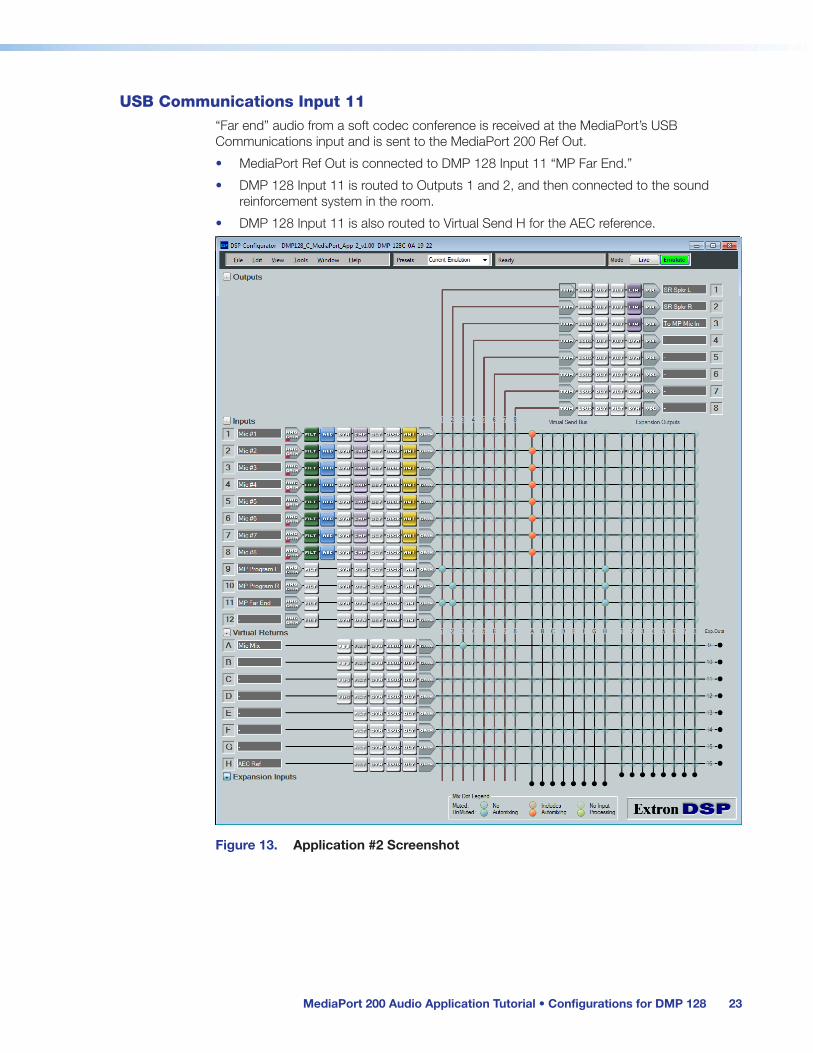
USB Communications Input 11“Far end” audio from a soft codec conference is received at the MediaPort’s USB Communications input and is sent to the MediaPort 200 Ref Out.
• MediaPort Ref Out is connected to DMP 128 Input 11 “MP Far End.”
• DMP 128 Input 11 is routed to Outputs 1 and 2, and then connected to the sound reinforcement system in the room.
• DMP 128 Input 11 is also routed to Virtual Send H for the AEC reference.
Figure 13. Application #2 Screenshot

MediaPort 200 Audio Application Tutorial • Configurations for DMP 128 24
Routing for Application #4
Mic Inputs 1 – 8• Microphone inputs are routed to the Virtual Send A, using the “Include Automixing”
routing option.
• From Virtual Return A, the Mic Mix is routed to Output 3. DMP 128 Output 3 is connected to the MediaPort 200 Mic/Line Input.
• In the DMP 128 AEC processing dialog, “AEC Ref (Virtual Return #H)” is assigned as the AEC reference for mic inputs 1 – 8.
• Virtual Return A is also routed to Output 4, connected to the video codec.
Program L/R Inputs 9 and 10Program content comes from the MediaPort 200 Line Output L/R, which is a mix of the USB Playback, HDMI, and Line Input signals.
• MediaPort 200 Line Output L/R is connected to the DMP 128 Inputs 9 and 10 “MP Program L/R.”
• DMP 128 Inputs 9 and 10 are routed to Output 4, summed to mono. Output 4 is connected to the video codec.
The mix‑points that connect Inputs 9 and 10 to Output 4 are set to ‑12dB. This is to compensate for summing, which can add up to 6dB of gain, and also to set a mix level for program audio to the video codec far end. This gain setting can be adjusted further during a test call to the video codec.
• DMP 128 Inputs 9 and 10 are routed to Virtual Sends B and C.
• From Virtual Returns B and C, program audio is routed to Outputs 1 and 2, and then connected to a stereo sound reinforcement system in the room. Virtual Returns B and C are also routed to Virtual Send H for the AEC reference.
USB Communications Input 11“Far end” audio from a soft codec conference is received at the MediaPort’s USB Communications input and is sent to the MediaPort 200 Ref Out.
• MediaPort Ref Out is connected to DMP 128 Input 11 “MP Far End.”
• DMP 128 Input 11 is routed to Output 4. Output 4 is connected to the video codec.
• DMP 128 Input 11 is routed to Virtual Send D.
• From Virtual Return D, USB Communcations is routed to Outputs 1 and 2, and then connected to the sound reinforcement system in the room. Virtual Return D is also routed to Virtual Send H for the AEC reference.

MediaPort 200 Audio Application Tutorial • Configurations for DMP 128 25
Video Codec Input 12 “Far end” audio from a hardware video codec conference line output is connected to DMP 128.
• Video codec line out is connected to DMP 128 Input 12 “Video Codec.”
• DMP 128 Input 12 is routed Output 3. Output 3 is connected to the MediaPort 200 Mic/Line Input.
• DMP 128 Input 12 is routed to Virtual Send E.
• From Virtual Return E, the video codec is routed to Outputs 1 and 2, which is connected to the sound reinforcement system in the room. Virtual Return E is also routed to Virtual Send H for the AEC reference.
Figure 14. Application #4 Screenshot

MediaPort 200 Audio Application Tutorial • Configurations for DMP 128 26
Control – Application #2Control points are pre‑configured in DSP Configurator. These controls can be adjusted from the DSP Configurator application, and designed into a control system for end‑user control. Control points are created from group master controls, which provide a single point of control, with the ability to adjust soft limits.
Program — Master VolumeA master control for the program mix is located at the input pre‑mixer gain point, labeled “MP Program L/R.” This control will adjust the volume level for program content in the room. Because the master control is located before the routing to the AEC reference, it will also affect the level going to the AEC reference so that the reference level will track with the room listening (volume) level for program content.
Program — Master MuteA master volume control for the program mix is located at the Input 9 and 10 pre‑mixer gain points, for input channels “MP Program L/R.” This control will mute the program content to both the local room and the far end
Far End — Master VolumeA master control for the far end audio from MediaPort is located at the input pre‑mixer gain point, labeled “MP Far End.” This control will adjust the volume level for far end audio reinforced in the local room. Because the master control is located before the routing to the AEC reference, it will also affect the level going to the AEC reference so that the reference level will track with the room listening (volume) level for far end audio.
Far End — Master MuteA master mute control for the “MP Far End” feed is located at the Input 11 pre‑mixer gain points. This control will mute the MediaPort USB Communications “far end” signal to the local room.
Privacy Mute — Master MuteA master mute control for the microphone mix is located at the Virtual Return A pre‑mixer gain point, labeled “Privacy Mute.” This control mutes the mic mix routed to Output #3, connected to the MediaPort 200 Mic/Line Input, and ultimately to the far end of a soft codec conference. This control can be used for privacy during a conference call, to mute the near end mics going to the far end while still being able to hear the far end.

MediaPort 200 Audio Application Tutorial • Configurations for DMP 128 27
Group MastersThe following is a list of groups for Application #2. Groups are created and ordered in this fashion so that mute groups will align vertically with the corresponding gain group that controls volume.
Group Name Group Number
Description
Program (fader) 2 Volume control for program audio to local room
Program (mute) 13 Mute control for program audio to local room
Far End (fader) 3 Volume control for far end audio (from MediaPort) to local room
Far End (mute) 14 Mute control for far end audio (from MediaPort) to local room
Privacy Mute 12 Mutes local mics for private discussion
Figure 15. Application #2 Group Controls

MediaPort 200 Audio Application Tutorial • Configurations for DMP 128 28
Control – Application #4Control points are pre‑configured in DSP Configurator. These controls can be adjusted from the DSP Configurator application, and designed into a control system for end‑user control. Control points are created from group master controls, which provide a single point of control, with the ability to adjust soft limits.
Program — Master VolumeA master volume control for the program mix is located at the Virtual Return B and C pre‑mixer gain points, for channels “MP Program L/R.” This control will adjust the volume level for program content in the local room, while not affecting the level to the far end. Because the master control is located before the routing to the AEC reference, it will also affect the level going to the AEC reference so that the reference level will track with the room listening (volume) level for program content.
Program — Master MuteA master mute control for the program mix is located at the Input 9 and 10 pre‑mixer gain points, for input channels “MP Program L/R.” This control will mute the program content to both the local room and the far end.
Far End — Master VolumeA master control for the far end audio from MediaPort is located at the input pre‑mixer gain point, labeled “MP Far End.” This control will adjust the volume level for far end audio reinforced in the local room. Because the master control is located before the routing to the AEC reference, it will also affect the level going to the AEC reference so that the reference level will track with the room listening (volume) level for far end audio.
Far End — Master MuteA master mute control for the USB Communications feed (labeled “MP Far End”) is located at the Input 11 pre‑mixer gain point. This control will mute the far end signal to both the local room and the video codec.
Video Codec — Master VolumeA master control for the far end audio from the hardware video codec is located at the Virtual Return B pre‑mixer gain point, labeled “Video Codec.” This control will adjust the volume level for far end audio in the room. Because the master control is located before the routing to the AEC reference from Virtual Send H, it will also affect the level going to the AEC reference so that the reference level will track with the room listening (volume) level for far end audio from the hardware video codec (only).
Video Codec — Master MuteA master mute control for the Video Codec feed is located at the Input 12 pre‑mixer gain point. This control will mute the Video Codec signal to both the local room and the MediaPort 200.

MediaPort 200 Audio Application Tutorial • Configurations for DMP 128 29
Privacy Mute — Master MuteA master mute control for the microphone mix is located at the Virtual Return A pre‑mixer gain point, labeled “Privacy Mute.” This control mutes the mic mix routed to Output #3, connected to the MediaPort 200 Mic/Line Input, and ultimately to the far end of a soft codec conference. This control can be used for privacy during a conference call, to mute the near end mics going to the far end while still being able to hear the far end.
Group MastersThe following is a list of groups for Application #4. Mute groups align vertically with the corresponding gain group that controls volume.
Group Name Group Number
Description
Program (fader) 2 Volume control for program audio to local room
Program (mute) 13 Mute control for program audio to local room
Far End (fader) 3 Volume control for far end audio (from MediaPort) to local room
Far End (mute) 14 Mute control for far end audio (from MediaPort) to local room
Video Codec (fader) 4 Volume control for video codec audio to local room
Video Codec (mute) 15 Mute control for far end audio to local room and MediaPort
Privacy Mute 12 Mutes local mics for private discussion
Figure 16. Application #4 Group Controls

MediaPort 200 Audio Application Tutorial • Configurations for DMP 128 30
Gain and DSP ProcessingThe templates provide the necessary routing as it applies to Applications #2 and #4 described in the Audio Application Setup section on page 1 of this user guide, as well as control hooks for use with a control system. Certain processing blocks have also been pre‑configured within the DSP Configurator templates. Adjustments may be needed for specific source devices and microphones, while gain settings will need to be made to achieve optimal gain structure. Extron Building Blocks can be used to configure any of the following signal chains for gain and processor settings (see the DMP 128 User Guide or DSP Configurator Help File for information about Building Blocks).
Input Signal Chain (Microphones)Microphone input channels contain basic filter and compressor processors for microphone signals. Eight microphone channels are configured. Unused channels can be reset to defaults, or hidden.
Gain
The default input gain setting is 0 dB, muted, with phantom power off. Gain and phantom power must be set for each individual microphone, according to mic sensitivity, mic type, proximity to the talker, talker characteristics, etc. Extron Building Blocks will make these settings for an extensive list of microphones. See the DSP Configurator Help File for more information on inserting Building Blocks.
Wireless microphones typically have a line level output. A setting of 0 dB may work for a balanced, pro line level output of +4 dBu, while an input gain setting of +11.8 dB will bring an unbalanced, consumer level output of −10 dBV up to pro (+4 dBu) line level. Some additional adjustment may be necessary, depending on the talker and other settings on the mic receiver.
Filters
A high‑pass filter is present to attenuate rumble and pops. A bass and treble filter is also inserted, but with no gain settings.
Dynamics Processing
A compressor is present with a gentle ratio and high threshold that will engage the compressor at higher gain levels. This will have the effect of normalizing the microphone levels for louder talkers.
AEC and Automixer
AEC and Automixer are processors that are essential to conferencing. These processors are not part of the Building Block set of input processors, and will remain unaffected if Building Blocks are used.
The AEC is set to a reference channel that is part of the template configuration, and should not be changed. If input gain and reference levels are set properly, often no further adjustments to the AEC settings will need to be made.
An Automixer has been inserted into the mic input signal path, controlling the number of microphones that can be open at any time during a conference. The use of an automixer will greatly contribute to intelligibility. The default settings are used. Therefore, it should be verified that microphones are turning on at the proper time while the system is in use or being tested. If microphones are not gating on and off properly, adjustments to the threshold and other parameters may need to be made. For more information, see the DMP 128 User Guide.

MediaPort 200 Audio Application Tutorial • Configurations for DMP 128 31
Input Signal Chain (Line Level Devices)The default input gain setting is 0 dB. For devices with a line level output, a setting of 0 dB may work for a balanced, pro line level output of +4 dBu, while an input gain setting of +11.8 dB will bring an unbalanced, consumer level output of −10 dBV up to pro (+4 dBu) line level. Some additional adjustment may be necessary, depending on other settings on the device.
Output Signal Chain
Gain
All output gain controls are set to 0 dB, or “unity gain.” For outputs 1 and 2, connected to a sound system, input sensitivity should be set on the receiving amplifier such that clipping on the amp does not occur. Many amplifiers have an input sensitivity of +4 dBu; therefore, a setting of –17 dBu works well. Often, the 12:00 position on the amplifier input knob is close to this setting, and will work well while providing an easily repeatable position for input sensitivity.
For output 3, no adjustment should be necessary for the input to the MediaPort Mic/Line In. The unity gain setting should work well for output 4, though an input gain setting may be necessary on the hardware video codec.
Limiter
A limiter is placed on the output signal chain to prevent clipping and protect connected devices. The threshold for the limiter is set to –3 dBFS. If the output signal stays at the –3 dBFS point for extended periods of time, you might hear the limiting of the dynamic range of the signal. In this case, you may want to lower the output gain control by 5 dB.

MediaPort 200 Audio Application Tutorial • Gain Structure 32
Gain Structure
Proper gain structure is essential to achieving optimal performance from the MediaPort 200 and related equipment. Refer to the Extron white paper, Audio Gain Structure for Pro AV Systems, for detailed information.
NOTE: To view the white paper, an Extron Insider account is required.
MediaPort 200Extron Product Configuration Software (PCS) provides a tabbed interface for setting audio gain and mixing audio levels within the MediaPort 200.
Input tabSetting proper input gain is fundamental to any audio device, and therefore, the Input tab is placed first in the Audio Config section of PCS. The MediaPort 200 uses digital peak meters, referenced to 0 dBFS, or “full scale.” The strongest level that can be achieved without clipping is the optimal signal level, in other words, approaching 0 dBFS yet with sufficient headroom to never reach 0 dBFS, which is clipping. Clipping a digital audio device produces immediately audible and undesirable distortion.
In order to achieve this optimal level without clipping, a strong yet safe target signal level must be established. To derive a dBu equivalent on the MediaPort peak meter referenced to 0 dBFS, the MediaPort max input level of +21 dBu must be considered. Subtracting 17 dB from +21 dBu gives us +4 dBu. Therefore, −17 dBFS on the MediaPort input meters is the approximate equivalent to +4 dBu.
With −17 dBFS as a target, the average audio signal will be −17 dBFS while varying approximately ±10 dB above or below that level. That would put the strongest, or “hottest” signal at about −6 to −8 dBFS. This is a safe level for program or microphone signals.
Mix tabWhen input gain is properly set, all listening levels can be set and run‑time operation can then be performed from the mix tab. Line Inputs and USB Communications levels have a range of −100 to +12 dB, but it is recommended to avoid going above 0 dB as this may cause clipping. There may be cases where the extra gain is needed. The Mix tab contains a Room Volume control, which may be the only control that needs adjustment once other controls are properly set. See section, Using the Mix Tab on page 10 in the user guide.

MediaPort 200 Audio Application Tutorial • Gain Structure 33
Output tabOn the Output tab, levels are set relative to the destination device. In most cases, the default setting of 0 dB is proper (no adjustment), which is why the Output tab is the last audio control tab in the Audio Config section.
Adjusting the Output Levels
Since the USB output and the line output contains mixes of different audio signals, it is important here to test the system and monitor these outputs to ensure that the signal level approaches 0 dBFS, yet with enough headroom to avoid clipping. If the meters show clipping, the fader control on the output can be lowered to bring the signal down below 0 dBFS. If the clipping is occurring at the input, however, lowering the output fader control will not eliminate the clipping. The input gain control must be lowered in this case.
If the output meter shows clipping and there is no clipping occurring at the input, then lowering the output fader control will eliminate the clipping in most cases. Within the MediaPort digital signal path, there is a certain amount of headroom, such that a signal or mix of signals that is too hot at the output can be lowered at the output fader control to eliminate clipping.
If lowering the output fader control prevents clipping at the output meter, but clipping is still audible (and there is no clipping present at the input meters), then levels must be lowered in the Mix tab to eliminate clipping. The Room Volume in the Near End section (and the Mic and Program controls in the Mix to Far End section) are all master controls that include soft limit controls. Setting the soft limit so that the fader cannot go above a level that causes clipping is a method of controlling clipping from the Mix tab. Otherwise, it will be necessary to lower faders in the Program Mix section and/or the USB Communications fader. Check the output meter often to verify that clipping does not appear on the meter.
Connecting to a DSP Processor
The USB Out is a digital level sent to the computer, so if your signal is optimal at this output, no attenuation should be needed. The AEC REF and Aux outs are intended to be sent to an external DSP processor. The MediaPort line level out is connected to the DSP processor line level in, and as long as the MediaPort max output level is the same or very similar to the DSP processor mix input level, little or no adjust to the MediaPort output level may be needed. This is also true of the MediaPort line output if connected to a DSP processor.
Connecting to an Amplifier
When the line output is connected to a sound reinforcement system, the amplifier of the sound system must be set to accommodate the output level of the MediaPort. If adjusting the amplifier input sensitivity instead of the MediaPort line output level, the Line Out attenuation control set to 0 dB will give the best signal to noise results. See section, Sound Reinforcement System on page 34 for more information.

MediaPort 200 Audio Application Tutorial • Gain Structure 34
External ProcessorsThe gain structure principals for MediaPort 200 can be directly applied to an external processor such as a DSP matrix processor or hardware video codec. In either case, strong signal levels that approach but do not exceed clipping levels are considered optimal. Maintaining these signal levels can be expressed as keeping “unity gain” throughout the system. Proper gain structure will consistently maintain the best signal‑to‑noise ratio within and between devices.
Peak Meters in dBFSIf the external device uses the same type of metering as the MediaPort 200, then maintaining unity gain between devices becomes simpler. For instance, if the MediaPort line output has a maximum level at −10 dBFS, then set the line input of the external device to have a maximum level of −10 dBFS.
Some devices, however, may use a scale that matches a dBu scale, with the highest point being the maximum input or output level of that device, such as +20 dBu. Additionally, that meter may be a peak meter, or it may show an average or RMS value. It is important to identify the type of meters that the external device is using.
Peak Meters in dBuIf the device uses a dBu scale with peak meters, the math is fairly simple. If, for example, the MediaPort shows a maximum level of −10 dBFS (10 dB below clipping), and the external device has a scale with 20 dBu as the maximum level, then a meter level of +10 dBu (10 dB below clipping) on the external device would be unity gain.
RMS Meters in dBuThe conversion from peak to RMS is not as straightforward. “Crest factor” is the ratio of peak to RMS values, and for music it is considered to have a range of 4 to 10, which converts to 12 to 20 dB differential. Using the maximum crest factor (20 dB) as a safe level, a common calibration used is to match +4 dBu to −20 dBFS. This can be done using a sine wave from a signal generator, where a reading of −20 dBFS on the MediaPort should equal +4 dBu on an RMS meter. This can also be done visually using program material, comparing the peak and RMS meters at a specific point in time.
Sound Reinforcement SystemA typical sound reinforcement system includes a power amplifier and speakers. In most cases, the input sensitivity of an amplifier has a maximum of +4 dBu. The max output of the MediaPort is +21 dBu, so attenuation of the amplifier input sensitivity is recommended. An input sensitivity of −12 to −17 dB on the amplifier should work well, but this may require testing the system and the fine‑tuning the settings. The target SPL level for the application must also be taken into consideration.
The gain structure article referenced at the beginning of this section suggests an amplifier input setting of 12 o’clock, which usually falls in the aforementioned range. The 12 o’clock setting is convenient and, most importantly, easily repeatable, and therefore, highly recommended as a best practice.

Extron Headquarters+1.800.633.9876 (Inside USA/Canada Only)
Extron USA - West Extron USA - East +1.714.491.1500 +1.919.850.1000 +1.714.491.1517 FAX +1.919.850.1001 FAX
Extron Europe+800.3987.6673 (Inside Europe Only)
+31.33.453.4040 +31.33.453.4050 FAX
Extron Asia+65.6383.4400+65.6383.4664 FAX
Extron Japan+81.3.3511.7655+81.3.3511.7656 FAX
Extron China+86.21.3760.1568 +86.21.3760.1566 FAX
Extron Middle East+971.4.299.1800+971.4.299.1880 FAX
Extron Korea+82.2.3444.1571+82.2.3444.1575 FAX
Extron India1800.3070.3777 Inside India Only
+91.80.3055.3777 +91.80.3055.3737 FAX
© 2015 Extron Electronics All rights reserved. www.extron.com
Contact Information
Extron Warranty
Extron Electronics warrants this product against defects in materials and workmanship for a period of three years from the date of purchase. In the event of malfunction during the warranty period attributable directly to faulty workmanship and/or materials, Extron Electronics will, at its option, repair or replace said products or components, to whatever extent it shall deem necessary to restore said product to proper operating condition, provided that it is returned within the warranty period, with proof of purchase and description of malfunction to:
USA, Canada, South America, and Central America: Extron Electronics 1230 South Lewis Street Anaheim, CA 92805 U.S.A.
Japan: Extron Electronics, Japan Kyodo Building, 16 Ichibancho Chiyoda‑ku, Tokyo 102‑0082 Japan
Europe and Africa: Extron Europe Hanzeboulevard 10 3825 PH Amersfoort The Netherlands
China: Extron China 686 Ronghua Road Songjiang District Shanghai 201611 China
Asia: Extron Asia Pte Ltd 135 Joo Seng Road, #04‑01 PM Industrial Bldg. Singapore 368363 Singapore
Middle East: Extron Middle East Dubai Airport Free Zone F13, PO Box 293666 United Arab Emirates, Dubai
This Limited Warranty does not apply if the fault has been caused by misuse, improper handling care, electrical or mechanical abuse, abnormal operating conditions, or if modifications were made to the product that were not authorized by Extron.
NOTE: If a product is defective, please call Extron and ask for an Application Engineer to receive an RA (Return Authorization) number. This will begin the repair process. USA: 714.491.1500 or 800.633.9876 Europe: 31.33.453.4040 Asia: 65.6383.4400 Japan: 81.3.3511.7655
Units must be returned insured, with shipping charges prepaid. If not insured, you assume the risk of loss or damage during shipment. Returned units must include the serial number and a description of the problem, as well as the name of the person to contact in case there are any questions.
Extron Electronics makes no further warranties either expressed or implied with respect to the product and its quality, performance, merchantability, or fitness for any particular use. In no event will Extron Electronics be liable for direct, indirect, or consequential damages resulting from any defect in this product even if Extron Electronics has been advised of such damage.
Please note that laws vary from state to state and country to country, and that some provisions of this warranty may not apply to you.