in this issue parts of a rocket - apogee rocketsin this issue parts of a rocket. about this...
TRANSCRIPT

ISSUE 426 September 20th 2016
www.apogeerockets.com/Rocket_Kits/Skill_Level_2_Kits/Magnum_Sprint
I N T H I S I S S U E
Parts of a Rocket

Continued on page 3About this NewsletterYou can subscribe to receive this e-zine FREE at the Apogee Components website www.ApogeeComponents.com, or by clicking the link
here Newsletter Sign-Up
Newsletter StaffWriter: Tim Van MilliganLayout/Cover Artist: Chris DuranProofreader: Michelle Mason
Parts of a RocketBy Tim Van Milligan
What is that thingy called? You know, it attach-es to the tube at the bottom of the rocket?
Every day new people enter the hobby of mod-el rocketry, and they get discouraged and they may feel embarrassed when they start talking to more seasoned flyers because they don’t know the proper names of the various parts in a rocket. We see this every day with students and teach-ers.
In this issue, I thought we’d review the basics of rocketry and go over the names of parts. In particular, I’m going to use a TARC style model rocket because I think it will help students when they are designing their own rockets. I’m sure that if they know the common names of parts, it will make it easier to search their favorite suppli-er’s web site to find the components they need for their design.
The first image shows the overall layout of a typical model rocket (Figure 1).
Nose Cone - Even though it is not “conical,” we still call it the nose ‘cone.’ The shape can vary, and in this image, it has an elliptical shape. This is the top most part of the model rocket.
Body Tube - This is a generic name for the tubes of the rocket. Typically the tubes are made from spiral wound paper. Here at Apogee Com-ponents, we call the paper tubes “airframe tubes” because they make up the frame of the rocket, and they travel through the air. We use the abbre-viation “AT” in the names of our own tubes. For example, an AT-24/18 is an Airframe Tube that is 24mm in diameter and 18 inches long. Sorry about mixing metric and English units, but since motors are measured in mm, we thought it would be better for customers.
Other manufacturers and suppliers use the BT designation for “body tube.” Then they use weird naming systems like BT-60. The number “60” doesn’t really stand for any particular mea-surable dimension. It is more like a numbering system. It is confusing, but that is life in rocketry. The naming of tubes is definitely an impediment to finding the parts that fit together. We recognize this at Apogee, and if you come to our web site you’ll find that we have actual dimensions for all the tubes we sell, and links to other products that mate with them. And if you search our web site for the name “body tubes,” you’ll find them easily enough.
Some tubes have special names, depending on where they are used in the rocket. For exam-ple:
Payload Tube - This is the airframe tube that the payload is put into. For a TARC rocket, the payload is the egg. Sometimes it might be elec-tronics, and then the specific tube is called an electronics-bay, or “e-bay” for short. Other people might call an e-bay an “avionics bay.”Figure 1: The basic part names of a typical model rocket.
Issue 426 | September 20th, 2016Page 2
www.ApogeeRockets.com/Rocket_Kits/Scale_Rockets
Continued on page 4
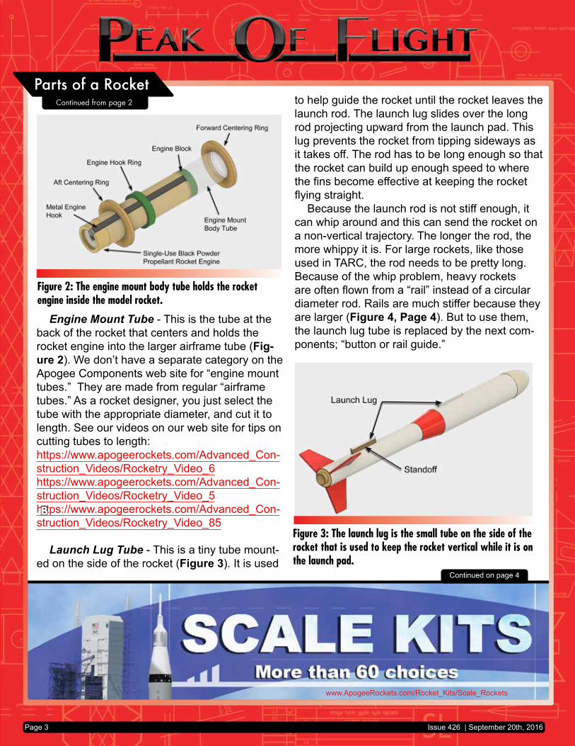
Engine Mount Tube - This is the tube at the back of the rocket that centers and holds the rocket engine into the larger airframe tube (Fig-ure 2). We don’t have a separate category on the Apogee Components web site for “engine mount tubes.” They are made from regular “airframe tubes.” As a rocket designer, you just select the tube with the appropriate diameter, and cut it to length. See our videos on our web site for tips on cutting tubes to length:https://www.apogeerockets.com/Advanced_Con-struction_Videos/Rocketry_Video_6https://www.apogeerockets.com/Advanced_Con-struction_Videos/Rocketry_Video_5https://www.apogeerockets.com/Advanced_Con-struction_Videos/Rocketry_Video_85
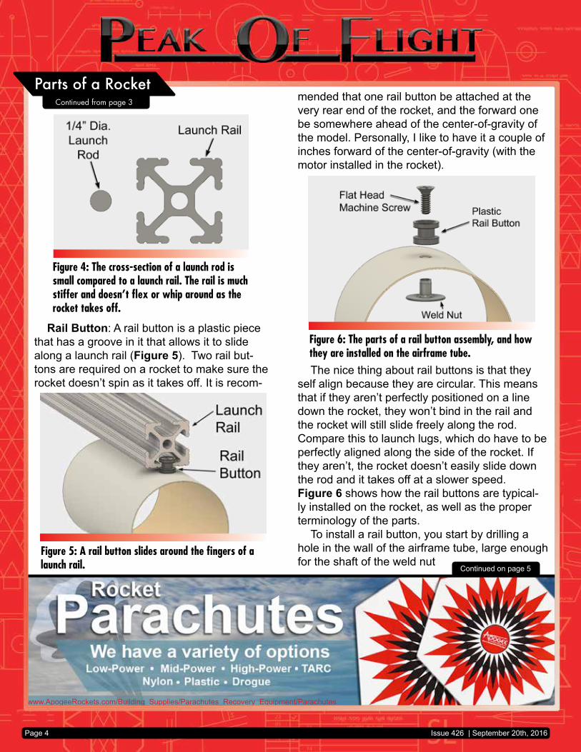
Launch Lug Tube - This is a tiny tube mount-ed on the side of the rocket (Figure 3). It is used
to help guide the rocket until the rocket leaves the launch rod. The launch lug slides over the long rod projecting upward from the launch pad. This lug prevents the rocket from tipping sideways as it takes off. The rod has to be long enough so that the rocket can build up enough speed to where the fins become effective at keeping the rocket flying straight.
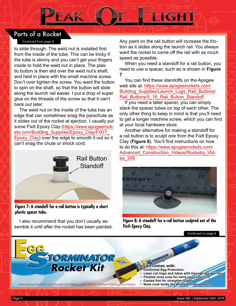
Because the launch rod is not stiff enough, it can whip around and this can send the rocket on a non-vertical trajectory. The longer the rod, the more whippy it is. For large rockets, like those used in TARC, the rod needs to be pretty long. Because of the whip problem, heavy rockets are often flown from a “rail” instead of a circular diameter rod. Rails are much stiffer because they are larger (Figure 4, Page 4). But to use them, the launch lug tube is replaced by the next com-ponents; “button or rail guide.”
Figure 3: The launch lug is the small tube on the side of the rocket that is used to keep the rocket vertical while it is on the launch pad.
B
Figure 2: The engine mount body tube holds the rocket engine inside the model rocket.
Parts of a Rocket
Issue 426 | September 20th, 2016Page 3
Continued from page 2
www.ApogeeRockets.com/Building_Supplies/Parachutes_Recovery_Equipment/Parachutes
Page 4
Continued on page 5
Rail Button: A rail button is a plastic piece that has a groove in it that allows it to slide along a launch rail (Figure 5). Two rail but-tons are required on a rocket to make sure the rocket doesn’t spin as it takes off. It is recom-
mended that one rail button be attached at the very rear end of the rocket, and the forward one be somewhere ahead of the center-of-gravity of the model. Personally, I like to have it a couple of inches forward of the center-of-gravity (with the motor installed in the rocket).
The nice thing about rail buttons is that they self align because they are circular. This means that if they aren’t perfectly positioned on a line down the rocket, they won’t bind in the rail and the rocket will still slide freely along the rod. Compare this to launch lugs, which do have to be perfectly aligned along the side of the rocket. If they aren’t, the rocket doesn’t easily slide down the rod and it takes off at a slower speed.Figure 6 shows how the rail buttons are typical-ly installed on the rocket, as well as the proper terminology of the parts.
To install a rail button, you start by drilling a hole in the wall of the airframe tube, large enough for the shaft of the weld nut
Figure 4: The cross-section of a launch rod is small compared to a launch rail. The rail is much stiffer and doesn’t flex or whip around as the rocket takes off.
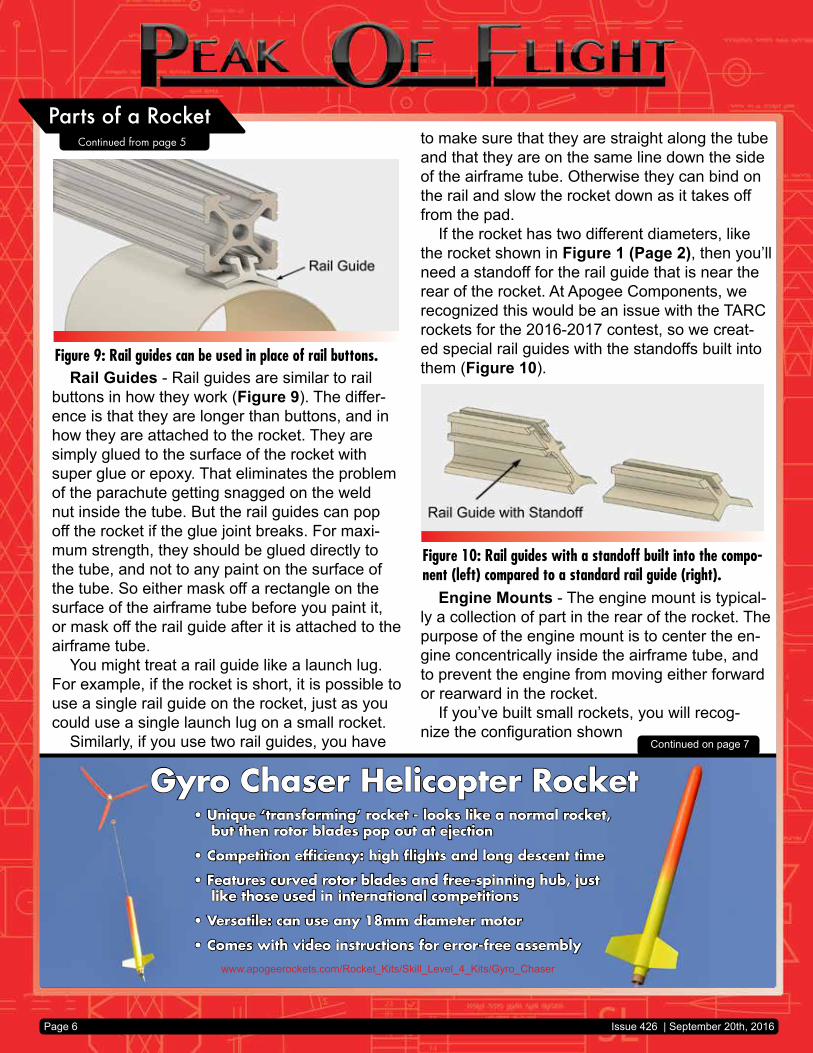
Figure 5: A rail button slides around the fingers of a launch rail.
Figure 6: The parts of a rail button assembly, and how they are installed on the airframe tube.
Parts of a Rocket
Issue 426 | September 20th, 2016
Continued from page 3
www.apogeerockets.com/Rocket-Kits/Skill-Level-4-Model-Rocket-Kits/EggStorminator
Page 5
to slide through. The weld nut is installed first from the inside of the tube. This can be tricky if the tube is skinny and you can’t get your fingers inside to hold the weld nut in place. The plas-tic button is then slid over the weld nut’s shaft, and held in place with the small machine screw. Don’t over tighten the screw. You want the button to spin on the shaft, so that the button will slide along the launch rail easier. I put a drop of super glue on the threads of the screw so that it can’t back out later.
The weld nut on the inside of the tube has an edge that can sometimes snag the parachute as it slides out of the rocket at ejection. I usually put some FixIt Epoxy Clay (https://www.apogeerock-ets.com/Building_Supplies/Epoxy_Clay/FIXIT_Epoxy_Clay) over the edge to smooth it out so it can’t snag the chute or shock cord.
I also recommend that you don’t usually as-semble it until after the rocket has been painted.
Any paint on the rail button will increase the fric-tion as it slides along the launch rail. You always want the rocket to come off the rail with as much speed as possible.
When you need a standoff for a rail button, you need to use a spacer, such as is shown in Figure 7.
You can find these standoffs on the Apogee web site at: https://www.apogeerockets.com/Building_Supplies/Launch_Lugs_Rail_Buttons/Rail_Buttons/5_16_Rail_Button_Standoff.
If you need a taller spacer, you can simply stack the spacer tubes on top of each other. The only other thing to keep in mind is that you’ll need to get a longer machine screw, which you can find at your local hardware store.
Another alternative for making a standoff for a rail button is to sculpt one from the FixIt Epoxy Clay (Figure 8). You’ll find instructions on how to do this at: https://www.apogeerockets.com/Advanced_Construction_Videos/Rocketry_Vid-eo_206
Continued on page 6
Figure 7: A standoff for a rail button is typically a short plastic spacer tube.
Figure 8: A standoff for a rail button sculpted out of the FixIt Epoxy Clay.
Parts of a Rocket
Issue 426 | September 20th, 2016
Continued from page 4
Gyro Chaser Helicopter Rocket• Unique ‘transforming’ rocket - looks like a normal rocket,
but then rotor blades pop out at ejection
• Competition efficiency: high flights and long descent time
• Features curved rotor blades and free-spinning hub, just like those used in international competitions
• Versatile: can use any 18mm diameter motor
• Comes with video instructions for error-free assembly
www.apogeerockets.com/Rocket_Kits/Skill_Level_4_Kits/Gyro_Chaser
Page 6
to make sure that they are straight along the tube and that they are on the same line down the side of the airframe tube. Otherwise they can bind on the rail and slow the rocket down as it takes off from the pad.
If the rocket has two different diameters, like the rocket shown in Figure 1 (Page 2), then you’ll need a standoff for the rail guide that is near the rear of the rocket. At Apogee Components, we recognized this would be an issue with the TARC rockets for the 2016-2017 contest, so we creat-ed special rail guides with the standoffs built into them (Figure 10).
Engine Mounts - The engine mount is typical-ly a collection of part in the rear of the rocket. The purpose of the engine mount is to center the en-gine concentrically inside the airframe tube, and to prevent the engine from moving either forward or rearward in the rocket.
If you’ve built small rockets, you will recog-nize the configuration shown
Continued on page 7
Rail Guides - Rail guides are similar to rail buttons in how they work (Figure 9). The differ-ence is that they are longer than buttons, and in how they are attached to the rocket. They are simply glued to the surface of the rocket with super glue or epoxy. That eliminates the problem of the parachute getting snagged on the weld nut inside the tube. But the rail guides can pop off the rocket if the glue joint breaks. For maxi-mum strength, they should be glued directly to the tube, and not to any paint on the surface of the tube. So either mask off a rectangle on the surface of the airframe tube before you paint it, or mask off the rail guide after it is attached to the airframe tube.
You might treat a rail guide like a launch lug. For example, if the rocket is short, it is possible to use a single rail guide on the rocket, just as you could use a single launch lug on a small rocket.
Similarly, if you use two rail guides, you have
Figure 9: Rail guides can be used in place of rail buttons.
Figure 10: Rail guides with a standoff built into the compo-nent (left) compared to a standard rail guide (right).
Parts of a Rocket
Issue 426 | September 20th, 2016
Continued from page 5
Electronics Hardware Installation KitThink of the convenience of getting everything to professionally install your dual-deployment or other electronic payload into a e-bay of your rocket!
https://www.apogeerockets.com/Electronics_Payloads/Electronics_Accessories/Electronics_Mounting_Kit
Includes: nylon stand-offs, screws & nuts, wire, push-switch, drill & tap, ejection charge cannisters, barrier strips, wire ties, and step-by-step DVD instructions.
Page 7
Continued on page 8
previously in Figure 2 (Page 3). It is typical of an engine mount used mostly for single-use black powder rocket engines. Here are some descrip-tions of some of the components.
Centering rings - The rings fit snugly over the engine mount body tube and inside the outer airframe tube. For small rockets, they are often made from paper that has been wound up in layers to provide the correct thickness. If the wall thickness gets much greater than around ¼-inch, the rings are cut from a flat sheet of material be-cause they are difficult to cut to the right length.Flat rings can be made from a variety of differ-ent rigid materials. Here at Apogee, we sell rings from foam-core poster board, cardstock, plywood and fiberglass (https://www.apogeerockets.com/Building_Supplies/Centering_Rings). That list is in order of lightest to heaviest weight. If you want to make your own rings, you’ll find a video on our web site at: https://www.apogeerockets.com/Ad-vanced_Construction_Videos/Rocketry_Video_24
Engine Block - The engine block is basically a centering ring that is glued into the engine mount body tube directly in front of the rocket engine. Its purpose is to prevent the rocket engine from sliding forward into the inside of the rocket.
Metal Engine Hook - The engine hook is a stiff piece of metal that is used to prevent the
engine from sliding rearward out the back end of the rocket. When the ejection charge fires after the motor has burned out, the force of the charge tries to push the motor out the back. If the motor is not restrained, then the parachute will not be blown out the front end and the rocket will come down ballistically.
Engine hooks are generally used in small and mid-size model rockets. They are typically not being used in large or high power rockets because they are not foolproof. The kick of the ejection charge can be so forceful that the hook might spring upward allowing the motor to be pushed out. What I do is wrap a piece of masking tape around the rear of the rocket engine over the top of the metal engine hook. This gives extra protection to make sure the motor stays in place throughout the entire flight.
I try to position all the parts in the engine mount so that the engine hangs out 1/2 -inch from the back edge of the engine mount tube. And the back edge of the aft centering ring is forward of the edge of the tube by ½ inch. This will allow the engine hook to be easily lifted up to allow a motor to be inserted easily into the engine mount tube.
Engine Hook Ring - If your rocket has an en-gine hook, there is a good chance that it has an engine hook ring too. This is a centering ring that fits over the top of the engine tube, but doesn’t fit all the way to the inside wall
Parts of a Rocket
Issue 426 | September 20th, 2016
Continued from page 6
Quick-Change Motor Adapters• Allows you to use smaller diameter motors in
your rocket kits (adds versatility)• Change out motors in seconds• Works with all single-use and re-loadable motors • Four sizes available
www.ApogeeRockets.com/Building_Supplies/Motor_Mount_Kits_Adapters/Ready-to-use_Motor_Adapters
Page 8
Continued on page 9
of the outer airframe tube. The purpose of the en-gine hook ring is to hold the engine hook and pre-vent it from pivoting side-to-side along the engine mount tube. The aft centering ring, if it is tight on the engine mount tube, can serve the same func-tion, so the extra ring isn’t always needed.
If my rocket has an aft centering ring, I’ll tem-porarily hold the engine hook to the engine mount tube with some masking tape. This will prevent it from pivoting and shifting on the tube until the aft ring has been glued into place. It is OK to leave the tape in place when the engine mount is in-stalled into the rocket. It doesn’t hurt the rocket at all.
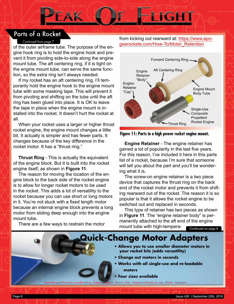
When your rocket uses a larger or higher thrust rocket engine, the engine mount changes a little bit. It actually is simpler and has fewer parts. It changes because of the key difference in the rocket motor. It has a “thrust ring.”
Thrust Ring - This is actually the equivalent of the engine block. But it is built into the rocket engine itself, as shown in Figure 11.
The reason for moving the location of the en-gine block to the back side of the rocket engine is to allow for longer rocket motors to be used in the rocket. This adds a lot of versatility to the rocket because you can use short or long motors in it. You’re not stuck with a fixed length motor because an internal engine block prevents a long motor from sliding deep enough into the engine mount tube.
There are a few ways to restrain the motor
from kicking out rearward at: https://www.apo-geerockets.com/How-To/Motor_Retention
Engine Retainer - The engine retainer has gained a lot of popularity in the last five years. For this reason, I’ve included it here in this parts list of a rocket, because I’m sure that someone will tell you about the part and you’ll be wonder-ing what it is.
The screw-on engine retainer is a two piece device that captures the thrust ring on the back end of the rocket motor and prevents it from shift-ing rearward out of the rocket. The reason it is so popular is that it allows the rocket engine to be switched out and replaced in seconds.
This type of retainer has two pieces as shown in Figure 11. The “engine retainer body” is per-manently attached to the aft end of the engine mount tube with high-tempera-
Figure 11: Parts in a high power rocket engine mount.
Parts of a Rocket
Issue 426 | September 20th, 2016
Continued from page 7
Page 9
Continued on page 10
ture epoxy. For this reason, you have to let the engine mount tube hang out the back at least ⅜ of an inch (9.5mm) for smaller motors, and even more for larger ones.
The “engine retainer cap” is removable and simply screws over the body when you want to hold the rocket engine in the rocket. The parts are either made from plastic or aluminum. You’ll find them on the Apogee website at: https://www.apogeerockets.com/Building_Supplies/Motor_Re-tainers_Hooks/.
Additional PartsI’d like to point out the names of some of the
additional parts you’ll come across. Again, the purpose is so that you’ll be able to speak to other rocketeers with clarity.
Fins - I really don’t need to point out the fin, but sometimes there is a portion on the fin that passes inside the body and is glued to the en-gine mount tube. This hidden portion of the fin is called the “fin tab.”
The reason to have a fin tab is to make a stronger fin attachment. By using this tab, you’ll have glue on two parts of the fin, not just one if you were to use a simple “butt-joint.” The butt-joint is common in smaller rockets. But as you
have probably experienced, the fins that are joined this way are easily snapped off after a hard landing. The “through-the-wall” fins, as fins are called when they have the fin tab, are much stronger and are used on rockets that require extra dura-bility or on higher powered rockets.
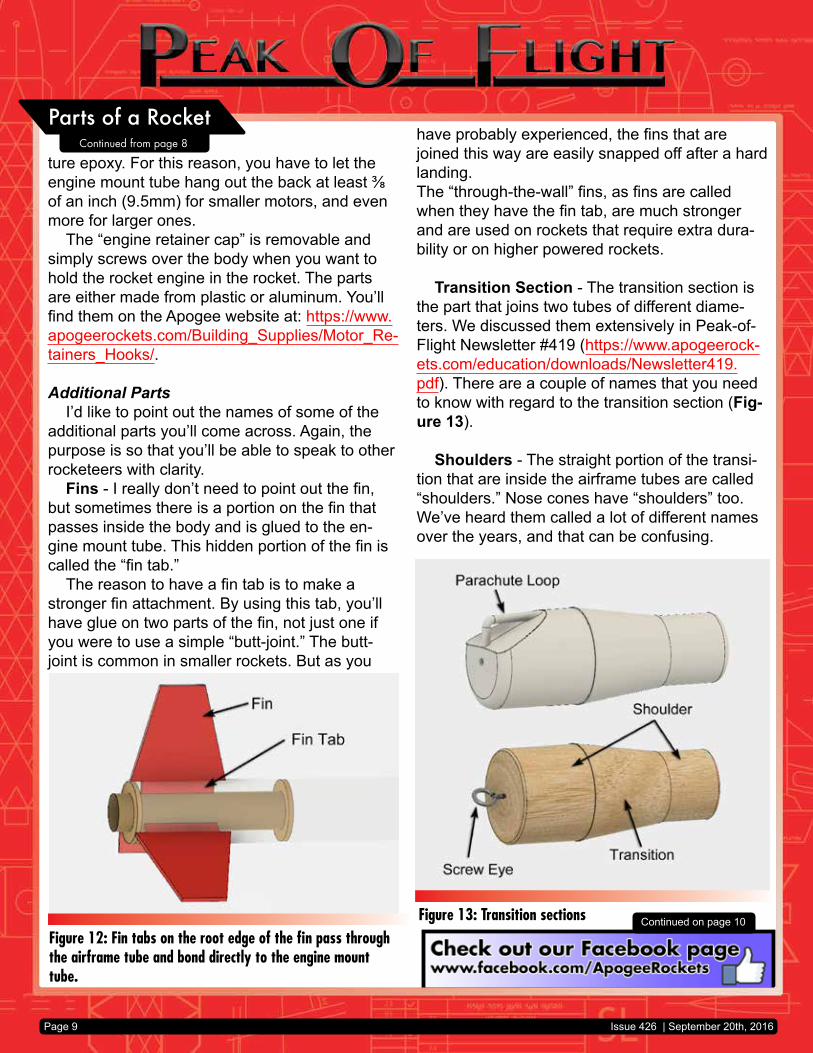
Transition Section - The transition section is the part that joins two tubes of different diame-ters. We discussed them extensively in Peak-of-Flight Newsletter #419 (https://www.apogeerock-ets.com/education/downloads/Newsletter419.pdf). There are a couple of names that you need to know with regard to the transition section (Fig-ure 13).
Shoulders - The straight portion of the transi-tion that are inside the airframe tubes are called “shoulders.” Nose cones have “shoulders” too. We’ve heard them called a lot of different names over the years, and that can be confusing.
Figure 12: Fin tabs on the root edge of the fin pass through the airframe tube and bond directly to the engine mount tube.
Figure 13: Transition sections
Parts of a Rocket
Issue 426 | September 20th, 2016
Continued from page 8

www.ApogeeRockets.com/Building_Supplies/Parachutes_Recovery_Equipment/Shock_Cord
You get:(4) AT 29/13(4) AT 41/18(2) AT 56/18(2) AT 66/18(1) AC-56(1) AC-66
You get:(6) AT 13/18(6) AT 18/18(6) AT 24/18(6) AT 33/18
www.ApogeeRockets.com/Building_Supplies/Body_Tubes
Page 10
is the owner of Apogee Components (http://www.apogeerockets.com) and also the author of the books: “Model Rocket Design and Construction,” “69 Simple Science Fair Projects with Model Rockets: Aeronautics” and publisher of the “Peak-of-Flight” newsletter, a FREE e-zine newsletter about model rockets. You can email him by using the contact form at: https://www.apogeerockets.com/Contact.
The place where the parachute and shock cords are attached have a couple of different names depending on how they are constructed. If it is a balsa wood transition, it will usually have a metal “screw eye” (Figure 13, Page 9) that is inserted directly into the wood.
Plastic nose cones and transitions have the attachment point molded as an integral part of the component. This attachment point is called the “parachute loop.” For transitions, there may be a parachute loop on both shoulder ends.
ConclusionThis list is really just the beginning of the ter-
minology used in rocketry. If you’re just getting started, it is probably enough to get you to the next level. But if you have any questions, please feel free to contact us at Apogee Components.
About The Author:Tim Van Milligan (a.k.a. “Mr. Rocket”) is a real
rocket scientist who likes helping out other rock-eteers. He is an avid rocketry competitor, and is Level 3 high power certified. He is often asked what is the biggest rocket he’s ever launched. His answer is that before he started writing arti-cles and books about rocketry, he worked on the Delta II rocket that launched satellites into orbit. He has a B.S. in Aeronautical Engineering from Embry-Riddle Aeronautical University in Daytona Beach, Florida, and has worked toward a M.S. in Space Technology from the Florida Institute of Technology in Melbourne, Florida. Currently, he
Parts of a Rocket
Issue 426 | September 20th, 2016
Continued from page 9