in-space. percutaneous interspinous distraction.synthes.vo.llnwd.net/o16/llnwmb8/int...
TRANSCRIPT

In-Space. Percutaneous interspinousdistraction.
Technique Guide

Synthes 1
WarningThis description is not sufficient for immediate application of the instrumentation. Instruction by a surgeon experiencedin handling this instrumentation is highly recommended.
Table of Contents
Image intensifier control
Introduction
Surgical Technique
Product Information
Features and Benefits 2
Indications and Contraindications 4
Preoperative Planning 5
Patient Positioning 6
Surgical Technique for Percutaneous Lateral Approach 7
Optional Technique in Case of Increased Insertion Forces 19
Technique for Removal of Outer Distraction Sleeve 21
Implant Removal 22
Implants 23
Instruments for Percutaneous Lateral Approach 24
Set List Instruments for Percutaneous Lateral Approach 28

Percutaneous lateral approachNo stripping of the paraspinal muscles
Tissue sparing procedureStabilizing anatomical structures arepreserved:– Supraspinous ligament is left intact– Interspinous ligament is only
pierced to the size of the implant– No bone needs to be trimmed
to facilitate the insertion of the implant
In-Space. Percutaneous interspinous distraction.

2
1
In-Situ deployment of theanchorageWhen turning the screw (1), the im-plant closes and the wings (2) are deployed along the spinous processes
Intrinsic stability– The wings prevent ventral and lateral
migration of the implant– The intact supraspinous ligament
prevents dorsal displacement

Contraindications– Severe Osteoporosis – Conus/Cauda syndrome– Severe structural spinal stenosis lacking a dynamic compo-
nent– Fractures – Spondylolisis– Degenerative spondylolisthesis at index level of grade > I
according to Meyerding– Scoliotic deformity at index level– DDD with fixed retrolisthesis– Sequestrated disc herniation– Previous surgery at the operative level– Spinous process and/or lamina dysplasia– Infection– Morbid obesity (BMI >40)
CautionThe stability of the In-Space relies on the presence of the following structures:– Supraspinous ligament– Laminae – Spinous processes – Facet joints
Complete or significant removal of those structures may re-sult in device migration.
4 Synthes In-Space Technique Guide
Intended useIn-Space is intended to stop the segmental extension and todistract the interspinous space at a symptomatic level be-tween L1 to L5. In-Space acts as a space-holder and protectsmainly the posterior elements by– maintaining the foraminal height,– opening up the area of the spinal canal,– reducing stress on the facet joints and– relieving pressure on the posterior annulus.
IndicationsIn-Space can be implanted at one or two levels from L1 to L5.
Based on the intended use, In-Space can be used for the following indications:– Central, lateral and foraminal lumbar spinal stenosis with
leg, buttock or groin pain, which can be relieved duringflexion
– Soft disc protrusions with discogenic low back pain– Facet syndrome due to facet osteoarthritis– Degenerative spondylolisthesis up to grade I with
hyperlordotic curve– Degenerative Disc Disease (DDD) with retrolisthesis– Interspinous pain arising from Baastrup syndrome
(“kissing spines”)
In-Space can also be used as a temporary implant in condi-tions which require a temporary unloading of the disc and/or facet joints.
Indications and Contraindications

Synthes 5
Preoperative Planning
In addition to routine preoperative investigations (X-rays APand lateral; MRI), flexion/extension views are strongly recom-mended. They provide a better understanding of the activeinterspinous flexibility and can rule out gross translational instability (e.g spondylolisthesis > grade I) or rigid retrolis the-sis.
A preoperative CT reconstruction is recommended in the following situations:– Suspicion of spinous process and/or lamina dysplasia– At L1–L3 to exclude that abdominal contents are located
posteriorly in trajectory of percutaneous approach.

6 Synthes In-Space Technique Guide
The use of a Wilson-like frame is recommended to decreasethe lordosis of the patient and to ensure that the abdomen isnot put under increased pressure. The table must be tiltableand radiolucent in both planes.
Place the patient in a comfortable prone position. It is advis-able to tilt the pelvis by inclining the table at the level ofthe pelvis. This will intraoperatively increase the segmentalkyphosis and achieve natural distraction of the interspinousspace.
Patient Positioning

Synthes 7
1Localize entry level
Define anatomical landmarks in projection to the skin level.
Under AP fluoroscopy, mark the midline projection of thespinous processes of the index level.
Under lateral fluoroscopy mark the projection of– the inferior rim of the superior spinous process (line in red),– the superior rim of the inferior spinous process
(line in blue),– and the posterior contour of the facet joint (line in green).
The entry point for the instruments (marked by a cross onthe drawing) is in the middle of the inferior and superior lineand just above the posterior contour line.
Surgical Technique forPercutaneous Lateral Approach

2 cm
1
2 2
8 Synthes In-Space Technique Guide
Surgical Technique for Percutaneous Lateral Approach
2Insert guide wire
Instruments
03.630.103 Guide Wire � 3.2 mm, length 260 mm
03.630.022 Aiming Device, radiolucent
03.630.104 Extension � 1.5 mm, length 400 mm
Make a longitudinal or transverse incision of approximately2 cm at the previously defined entry level.
Connect the guide wire to the aiming device. Introduce theguide wire into the aiming device until it reaches the stop.Tighten the set screw.
Introduce the guide wire through the incision. Under lateralfluoroscopy, carefully advance the guide wire between thespinous processes, keeping it parallel to the coronal plane.For an optimal ventral placement of the In-Space, the guidewire must be placed as far anterior as possible.
Note: The interspinous ligament gives a slightly increased resistance and must be perforated with the guide wire.
Under AP fluoroscopy, push the guide wire about 2 cmacross the midline (1).
Verify its correct position in both AP and lateral view.
Note: Under lateral fluoroscopy, the radiolucent aiming de-vice shows an aiming ring. This aiming ring can be used as apositioning guide. When the guide wire appears as a point,it is parallel to the fluoroscopy beam path (2).

3
3
Synthes 9
Release the set screw and remove the aiming device. To ex-tend the guide wire, push the extension for guide wire firmlyall the way down into the guide wire (3). Ensure that theguide wire cannot advance any further.
1
2
1
2
10 Synthes In-Space Technique Guide
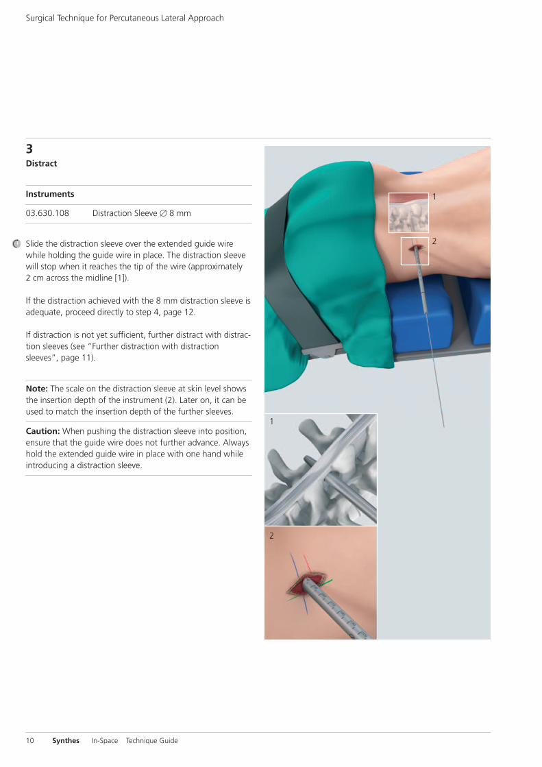
3Distract
Instruments
03.630.108 Distraction Sleeve � 8 mm
Slide the distraction sleeve over the extended guide wirewhile holding the guide wire in place. The distraction sleevewill stop when it reaches the tip of the wire (approximately2 cm across the midline [1]).
If the distraction achieved with the 8 mm distraction sleeve isadequate, proceed directly to step 4, page 12.
If distraction is not yet sufficient, further distract with distrac-tion sleeves (see “Further distraction with distractionsleeves”, page 11).
Note: The scale on the distraction sleeve at skin level showsthe insertion depth of the instrument (2). Later on, it can beused to match the insertion depth of the further sleeves.
Caution: When pushing the distraction sleeve into position,ensure that the guide wire does not further advance. Alwayshold the extended guide wire in place with one hand whileintroducing a distraction sleeve.
Surgical Technique for Percutaneous Lateral Approach

1
2
1
2 3
Synthes 11
Further distraction with distraction sleeves
Instruments
03.630.080 Distraction Sleeve � 10 mm
03.630.082 Distraction Sleeve � 12 mm
03.630.084 Distraction Sleeve � 14 mm
03.630.086 Distraction Sleeve � 16 mm
Slide the 10 mm distraction sleeve over the 8 mm distractionsleeve while holding the extended guide wire in place.
Note: Oscillating movements may ease the insertion of thedistraction sleeves through the soft tissues. However, full revolutions may wind up soft tissue around the instrumentsand should be avoided.
The tip of the distraction sleeve is designed to ease insertionof the sleeve between the spinous processes. When the tipof the distraction sleeve reaches the interspinous space (1),orient it in cranio-caudal direction: Rotate the sleeve until thewhite lines at its proximal end are parallel to the patient’scoronal plane (2).
The 10 mm distraction sleeve stops when it reaches the tipof the 8 mm distraction sleeve (3).
Repeat with sequentially larger distraction sleeves until thedesired distraction is achieved. The last inserted distractionsleeve should have a press fit contact to the cranial and caudal rim of the inferior and superior spinous processes.Verify the correct amount of distraction under fluoroscopy.
12 Synthes In-Space Technique Guide
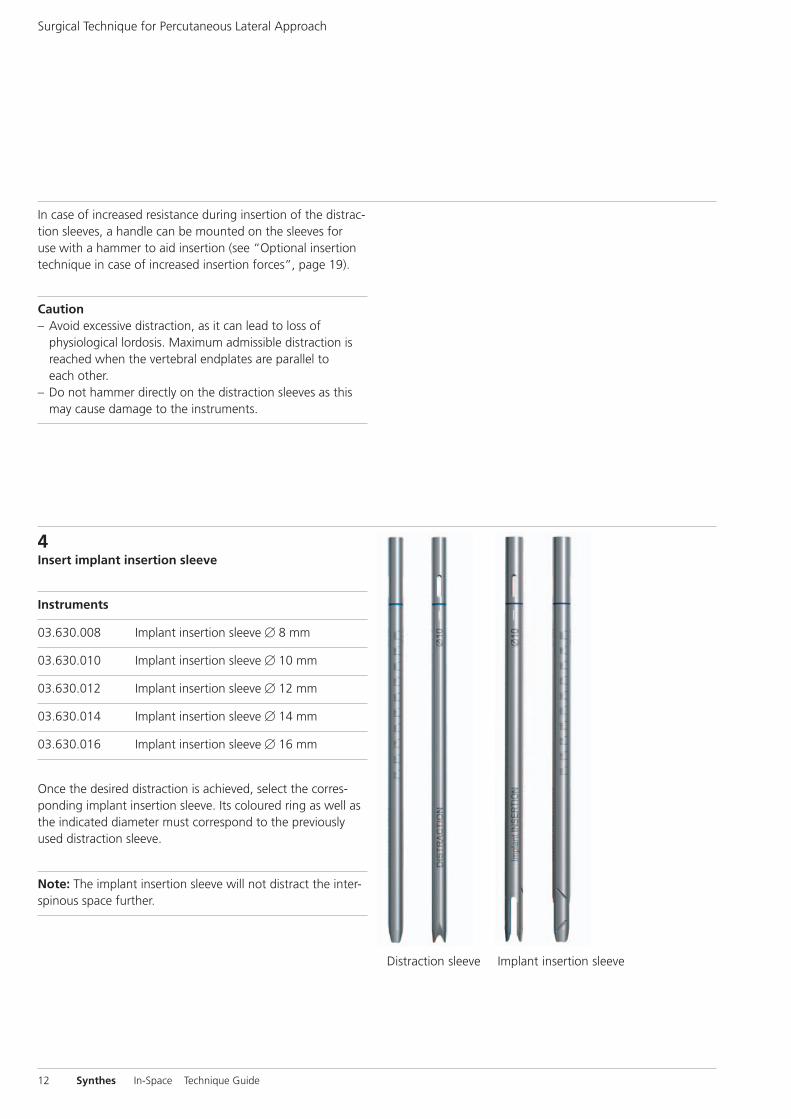
4Insert implant insertion sleeve
Instruments
03.630.008 Implant insertion sleeve � 8 mm
03.630.010 Implant insertion sleeve � 10 mm
03.630.012 Implant insertion sleeve � 12 mm
03.630.014 Implant insertion sleeve � 14 mm
03.630.016 Implant insertion sleeve � 16 mm
Once the desired distraction is achieved, select the corres-ponding implant insertion sleeve. Its coloured ring as well asthe indicated diameter must correspond to the previouslyused distraction sleeve.
Note: The implant insertion sleeve will not distract the inter-spinous space further.
Distraction sleeve Implant insertion sleeve
In case of increased resistance during insertion of the distrac-tion sleeves, a handle can be mounted on the sleeves foruse with a hammer to aid insertion (see “Optional insertiontechnique in case of increased insertion forces”, page 19).
Caution– Avoid excessive distraction, as it can lead to loss of
physiological lordosis. Maximum admissible distraction isreached when the vertebral endplates are parallel toeach other.
– Do not hammer directly on the distraction sleeves as thismay cause damage to the instruments.
Surgical Technique for Percutaneous Lateral Approach

2
1
2
1 3
4
3 mm
Synthes 13
Slide the implant insertion sleeve over the outer distractionsleeve while holding the extended guide wire in place.
Verify that the white lines at the proximal end of the implantinsertion sleeve (1) are oriented in cranio-caudal direction,parallel to the patient’s coronal plane. This will ease the inser-tion between the spinous processes (2).
The maximal insertion depth is reached when the transitionin diameter seen under AP fluoroscopy is approximately3 mm from the border of the spinous processes (3). Do notexceed this insertion depth (4).
Remove all the inner distraction sleeves. To do so, simply pullon the extended guide wire.
CautionIt is important to correctly orient the implant insertion sleevein the cranio-caudal direction. Incorrect orientation may result in:– Overdistraction of the interspinous space– Deployment of the implant wings in antero-posterior
direction.

14 Synthes In-Space Technique Guide
Under AP fluoroscopy, place the implant insertion sleeve inits final insertion depth. Visualize the 2 holes at the distalend of the sleeve. The virtual midpoint between these2 points defines the midline of the In-Space implant and hasto be in line with the spinous processes.
Surgical Technique for Percutaneous Lateral Approach
2
1
1
Synthes 15
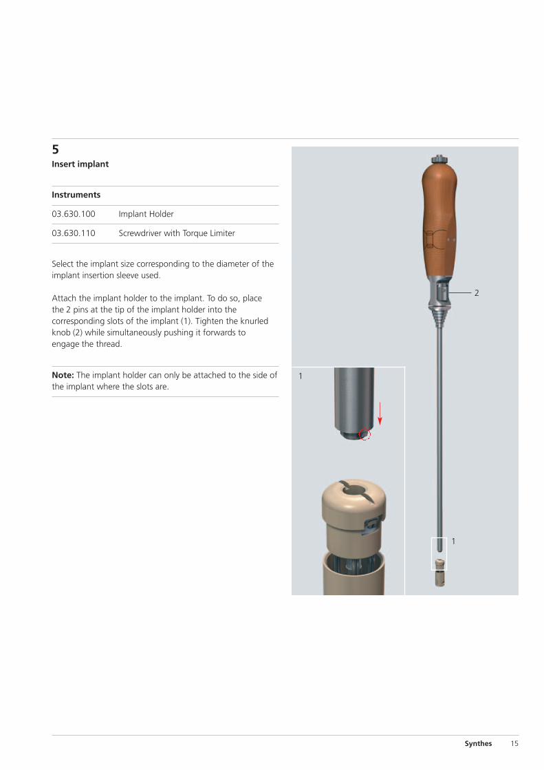
5Insert implant
Instruments
03.630.100 Implant Holder
03.630.110 Screwdriver with Torque Limiter
Select the implant size corresponding to the diameter of theimplant insertion sleeve used.
Attach the implant holder to the implant. To do so, placethe 2 pins at the tip of the implant holder into the corresponding slots of the implant (1). Tighten the knurledknob (2) while simultaneously pushing it forwards toengage the thread.
Note: The implant holder can only be attached to the side ofthe implant where the slots are.

1⁄4 turn
16 Synthes In-Space Technique Guide
Insert the implant holder into the implant insertion sleeve.Turn the holder slightly until the spherules of the holder snapinto the corresponding notch inside the insertion sleeve.Push the holder forwards and simultaneously rotate it by aquarter turn. This locks the implant holder into the sleeve.
Caution: Make sure not to adjust the insertion depth or the cranio-caudal orientation of the implant insertion sleevewhile inserting the implant holder.
Surgical Technique for Percutaneous Lateral Approach

1
2
1
Synthes 17
Introduce the screwdriver into the implant holder until theholding mechanism snaps in.
Turn the screwdriver clockwise to deploy the wings of theimplant. Under AP fluoroscopy, verify proper deploymentof the wings. When the wings are fully deployed, a distinctincrease in resistance is felt. A green coloured ring onthe screwdriver shaft must appear at the proximal end of theimplant holder (1).
Loosen the knurled knob (2) of the implant holder to detachit from the implant. Simultaneously remove the implantholder, the insertion sleeve and the screwdriver by pulling onthe implant holder.
Note: To avoid damaging the implant do not detach the im-plant holder from the insertion sleeve while removing them.

1
3
2
2
18 Synthes In-Space Technique Guide
Caution: Soft tissues or bone can hinder proper deployment of thewings. To avoid injury to these structures, a torque limiter hasbeen integrated in the screwdriver. If the maximally achiev-able torque is reached before the above mentioned greencoloured ring appears on the screwdriver shaft, this impliesthat the wings are not fully deployed and that the implant isnot completely closed. The distraction effect might be lostand migration could occur.
In this case it is recommended to remove and reposition theimplant. Turn the screwdriver anti-clockwise (1) until an increase in resistance is felt. Control under AP fluoroscopythat the wings are completely retracted. Pull back the collarof the implant holder (2) and turn the holder by a quarterturn (3) to release the implant holder from the insertionsleeve. Retract the holder together with the implant from theinsertion sleeve.
Ensure that no soft tissues are entrapped in the implant ob-structing proper deployment. Slightly adjust the positionof the insertion sleeve. Reintroduce the holder together withthe implant into the insertion sleeve and deploy the wirescorrectly.
Collar
1⁄4 turn
Surgical Technique for Percutaneous Lateral Approach

1
1
3
2
43
Synthes 19
Optional Technique in Case ofIncreased Insertion Forces
Instruments
03.630.024 Handle, for Distraction and InsertionSleeves
03.630.031 Hammer
In case of increased resistance during insertion of the distrac-tion and implant insertion sleeves a handle can be attachedto ease the insertion.
Loosen the knurled knob of the handle until the red line appears in the opening (1). This is the maximum open posi-tion. Make sure not to loosen past this point or the knob will disassemble from the handle.
Press the knob (2) to open the prongs of the handle (3). Slidethe handle over the sleeve and release the knob.
Note: Make sure that the ridges (3) in the handle aresnapped into the corresponding slots of the instrument. Usethe white lines (3) on the handle and on the sleeve for cor-rect rotational alignment of the two instruments.
Firmly tighten the knurled knob by hand (4).

20 Synthes In-Space Technique Guide
Slide the assembly over the sleeve.
Rotate the handle until the white lines are parallel to the patient’s coronal plane. This will guarantee the correctcranio-caudal orientation of the instruments and ease theirsmooth insertion between the spinous processes.
Gentle hammering on the handle with the slotted hammerallows a controlled, step by step insertion between the spinous processes. To do so, slide the hammer from the sidedirectly on the extension of the guide wire and rotate the instrument in the axis of the guide wire. Gently hammer.
Caution:– Do not hammer directly on the distraction sleeves or the
implant insertion sleeves (may cause damage to the instru-ments).
– Extreme care should be taken to avoid any injury of thespinous processes by excessive and/or heavy hammering.
Optional Technique in Case of Increased Insertion Forces
1 2
Synthes 21
Instruments
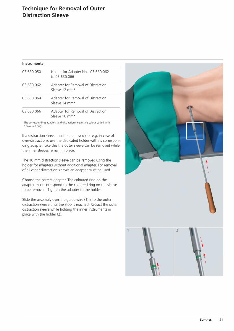
03.630.050 Holder for Adapter Nos. 03.630.062to 03.630.066
03.630.062 Adapter for Removal of Distraction Sleeve 12 mm*
03.630.064 Adapter for Removal of Distraction Sleeve 14 mm*
03.630.066 Adapter for Removal of Distraction Sleeve 16 mm*
*The corresponding adapters and distraction sleeves are colour coded witha coloured ring.
If a distraction sleeve must be removed (for e.g. in case ofover-distraction), use the dedicated holder with its correspon-ding adapter. Like this the outer sleeve can be removed whilethe inner sleeves remain in place.
The 10 mm distraction sleeve can be removed using theholder for adapters without additional adapter. For removalof all other distraction sleeves an adapter must be used.
Choose the correct adapter. The coloured ring on theadapter must correspond to the coloured ring on the sleeveto be removed. Tighten the adapter to the holder.
Slide the assembly over the guide wire (1) into the outer distraction sleeve until the stop is reached. Retract the outerdistraction sleeve while holding the inner instruments inplace with the holder (2).
Technique for Removal of OuterDistraction Sleeve

22 Synthes In-Space Technique Guide
Implant Removal
The implant can be removed through a conventional poste-rior approach. First, cut the wires and then remove the implant by pushing it on the side, displacing it from betweenthe spinous processes.
Synthes 23
Implants
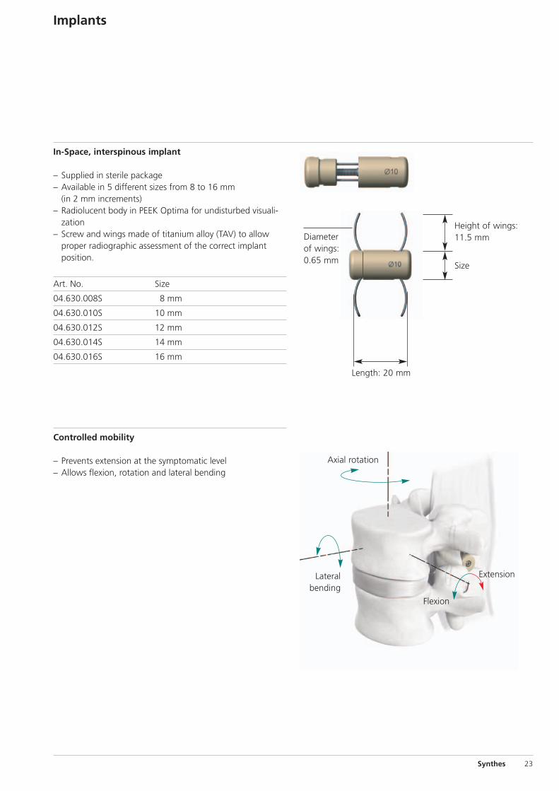
In-Space, interspinous implant
– Supplied in sterile package– Available in 5 different sizes from 8 to 16 mm
(in 2 mm increments)– Radiolucent body in PEEK Optima for undisturbed visuali-
zation– Screw and wings made of titanium alloy (TAV) to allow
proper radiographic assessment of the correct implant position.
Art. No. Size
04.630.008S 8 mm
04.630.010S 10 mm
04.630.012S 12 mm
04.630.014S 14 mm
04.630.016S 16 mm
Size
Height of wings:11.5 mm
Length: 20 mm
Diameterof wings:0.65 mm
Controlled mobility
– Prevents extension at the symptomatic level– Allows flexion, rotation and lateral bending
Lateralbending
Axial rotation
Extension
Flexion
24 Synthes In-Space Technique Guide
Instruments for Percutaneous LateralApproach
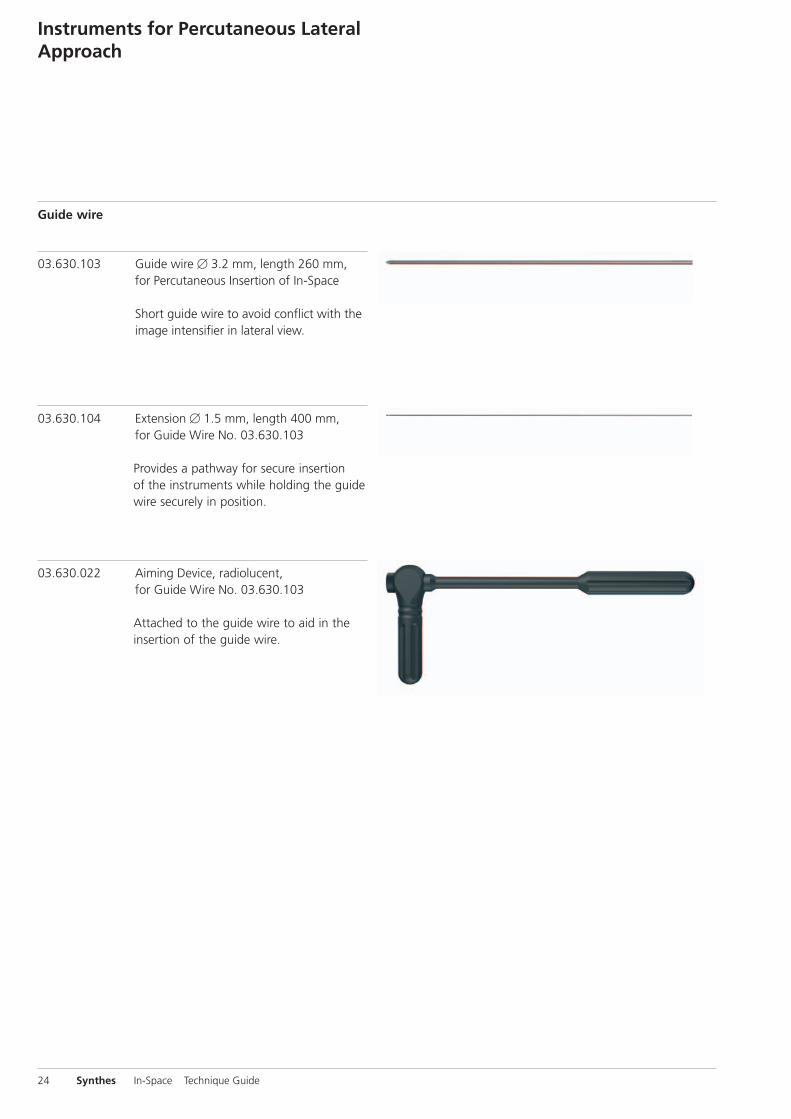
Guide wire
03.630.103 Guide wire � 3.2 mm, length 260 mm,for Percutaneous Insertion of In-Space
Short guide wire to avoid conflict with theimage intensifier in lateral view.
03.630.104 Extension � 1.5 mm, length 400 mm,for Guide Wire No. 03.630.103
Provides a pathway for secure insertionof the instruments while holding the guidewire securely in position.
03.630.022 Aiming Device, radiolucent, for Guide Wire No. 03.630.103
Attached to the guide wire to aid in theinsertion of the guide wire.

Synthes 25
Instruments for distraction
Lateral view Cranio-caudal view
03.630.108 Distraction sleeve � 8.0 mm, length 265 mm, for Percutaneous Insertionof In-Space
Gently dilates the soft tissues.
Distraction sleeves � 10–16 mm, for Percutaneus Insertionof In-Space
– Distract the interspinous space with the help of theconical tip.
– The nominal diameter on the sleeves corresponds to thediameter of the implant core.
Art. No. � Length
03.630.080 10 mm 268 mm
03.630.082 12 mm 271 mm
03.630.084 14 mm 274 mm
03.630.086 16 mm 277 mm

26 Synthes In-Space Technique Guide
Lateral view Cranio-caudal view
Instruments for implant insertion
Insertion Sleeves � 8–16 mm, for Percutaneous Insertion ofIn-Space
– Allow the deployment of the wires through the cranio-caudal opening at the tip of the instrument
– The slots on the side help define the midline of the implant– The nominal diameter on the sleeves corresponds to the di-
ameter of the implant core– The insertion sleeves are color coded with the correspon-
ding distraction sleeves
Art. No � Length
03.630.008 8 mm 265 mm
03.630.010 10 mm 268 mm
03.630.012 12 mm 271 mm
03.630.014 14 mm 274 mm
03.630.016 16 mm 277 mm
03.630.100 Implant Holder for Percutaneous Insertionof In-Space
For holding the implant and positioning itinto the interspinous space through theimplant insertion sleeves.
03.630.110 Screwdriver with Torque Limiter,for Percutaneous Insertion of In-Space
For a controlled in-situ deployment of the implant’s wings.
Instruments for Percutaneous Lateral Approach

Synthes 27
Instruments in case of increased insertion resistance
03.630.024 Handle for Distraction and InsertionSleeves, for In-Space
Used as a handle to ease the insertion ofthe distraction and implant insertionsleeves, if resistance is felt.
03.630.031 Hammer, for Percutaneous Insertion of In-Space
For gently hammering on the handle,if resistance is felt.
Instruments for removal of outer sleeves
In case of over-distraction; allow retracting the last distrac-tion sleeve while holding the smaller sleeves in position.
03.630.050 Holder for Adapter Nos. 03.630.062 to 03.630.066
For removal of distraction sleeve � 10 mmor used as a handle in connection with theadapters.
03.630.062 Adapter for removal of distraction sleeve �12 mm
03.630.064 Adapter for removal of distraction sleeve �14 mm
03.630.066 Adapter for removal of distraction sleeve �16 mm
Cleaning brushes for cannulated instruments
03.630.123 Cleaning brush � 2.9 mm, length 460 mm
03.630.125 Cleaning brush � 4.7 mm, length 380 mm

28 Synthes In-Space Technique Guide
Set List Instruments for PercutaneousLateral Approach
01.630.004 Instrument Set for Percutaneous Insertion of In-Space, in Vario Case
68.630.000 Vario Case for Percutaneous Instrument Set of In-Space, with Lid, without Contents
Instruments
03.630.008 Implant Insertion Sleeve � 8.0 mm, length 265 mm, for Percutaneous Insertion of In-Space
03.630.010 Implant Insertion Sleeve � 10.0 mm, length 268 mm, for Percutaneous Insertion of In-Space
03.630.012 Implant Insertion Sleeve � 12.0 mm, length 271 mm, for Percutaneous Insertion of In-Space
03.630.014 Implant Insertion Sleeve � 14.0 mm, length 274 mm, for Percutaneous Insertion of In-Space
03.630.016 Implant Insertion Sleeve � 16.0 mm, length 277 mm, for Percutaneous Insertion of In-Space
03.630.022 Aiming Device, radiolucent, for Guide Wire No. 03.630.103
03.630.024 Handle for Distraction and Insertion Sleeves, for In-Space
03.630.031 Hammer, for Percutaneous Insertion of In-Space
03.630.050 Holder for Adapter Nos. 03.630.062 to 03.630.066
03.630.062 Adapter for Removal of Distraction Sleeve � 12.0 mm
03.630.064 Adapter for Removal of Distraction Sleeve � 14.0 mm
03.630.066 Adapter for Removal of Distraction Sleeve� 16.0 mm
03.630.080 Distraction Sleeve � 10.0 mm, length 268 mm, for Percutaneous Insertion of In-Space
03.630.082 Distraction Sleeve � 12.0 mm, length 271 mm, for Percutaneous Insertion of In-Space
03.630.084 Distraction Sleeve � 14.0 mm, length 274 mm, for Percutaneous Insertion of In-Space
03.630.086 Distraction Sleeve � 16.0 mm, length 277 mm, for Percutaneous Insertion of In-Space
03.630.100 Implant Holder for Percutaneous Insertion of In-Space
03.630.103 Guide Wire � 3.2 mm, length 260 mm, for Percutaneous Insertion of In-Space
03.630.104 Extension � 1.5 mm, length 400 mm, for Guide Wire No. 03.630.103
03.630.108 Distraction Sleeve � 8.0 mm, length 265 mm, for Percutaneous Insertion of In-Space
03.630.110 Torque limiting Screwdriver for Percutaneous Insertion of In-Space
03.630.123 Cleaning Brush � 2.9 mm, length 460 mm
03.630.125 Cleaning Brush � 4.7 mm, length 380 mm
Implants
Implants are supplied sterile and must be ordered separately.


0123 036.
000.
405
SE_
1260
69 A
A
5007
0040
©
Syn
thes
20
07
Vario
Cas
e is
a t
rade
mar
k of
Syn
thes
Su
bjec
t to
mod
ifica
tions
Presented by:
Ö036.000.405öAArä