in-situ and induced stresses
TRANSCRIPT

IN-SITU AND INDUCED
STRESSES
1Created By: Shaloo Puri
Website: www.geotechnicaldesigns.com.au
Email id : [email protected]
WhatsApp: +61452075310
INTRODUCTION
www.geotechnicaldesigns.com.au
2
Rock at depth is subjected to stresses due to following
reasons:
1. Weight of overlying overburden pressures
2. Due to tectonic pressures
Stresses around tunnel opening
When opening is excavated in such rock there are
redistribution of these in-situ stresses and new set of
stresses induced around the opening

VERTICAL STRESSES Vertical Stress is usually governed by weight of the
overburden at certain rock element at certain depth.
Example :
Z = 1000m (overburden depth at certain rock element)
= 0.027MN/m3
The vertical stress = 27MPa
www.geotechnicaldesigns.com.au
3

VERTICAL STRESSES
www.geotechnicaldesigns.com.au
4
Measurements of vertical stress at various mining and civil engineering
sites around the world confirm that this relationship is valid although, as
illustrated in Figure 1, there is a significant amount of scatter in the
measurements.

HORIZONTAL STRESSES
www.geotechnicaldesigns.com.au
5
Horizontal Stresses are more difficult to determine that vertical stresses.
Normally, the ratio of the average horizontal stress to the vertical stress
is denoted by the letter k such that:
Sheorey Equation:
z (m) is the depth below surface
Eh (GPa) is the average deformation modulus of the upper part of
the earth’s crust measured in a horizontal direction.
HORIZONTAL STRESSES
www.geotechnicaldesigns.com.au 6
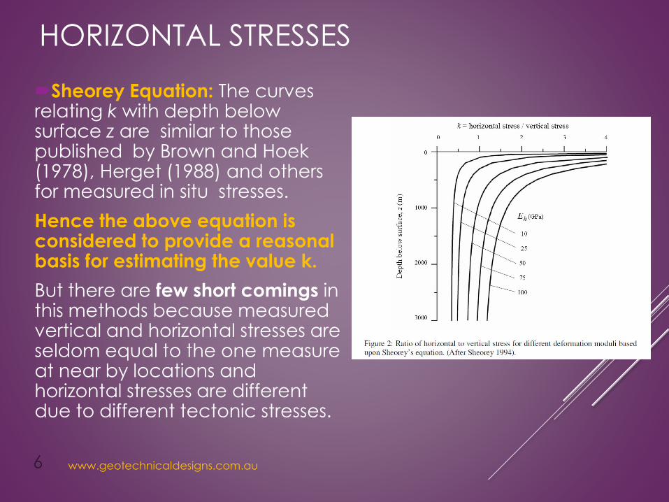
Sheorey Equation: The curves relating k with depth below surface z are similar to those published by Brown and Hoek (1978), Herget (1988) and others for measured in situ stresses.
Hence the above equation is considered to provide a reasonalbasis for estimating the value k.
But there are few short comings in this methods because measured vertical and horizontal stresses are seldom equal to the one measure at near by locations and horizontal stresses are different due to different tectonic stresses.

HORIZONTAL STRESSES
www.geotechnicaldesigns.com.au
7
Methods for measuring in-situ stresses
The most popular and reliable method of measuring in-situ
stresses are considered are:
1. Overcoring method
2. Hydraulic Fracturing Tests
I am not addressing these methods in this presentation.
It is very important to have measured in-situ stresses for
underground structures like tunnels , caverns and other type of
openings for hydropower projects and mining projects.

www.geotechnicaldesigns.com.au
8
STRESSES AROUND TUNNEL
When an underground opening is excavated into a stressed rock mass,
the stresses in the vicinity of the new opening are re-distributed.
v,h1, h2 are in-situ stresses
Before the excavation of tunnel
After removal of the rock from
within the tunnel, the stresses in
the immediate vicinity of the
tunnel are changed and new
stresses are induced.
1,2, 3 are principal
stresses at Rock element
near to the opening.
www.geotechnicaldesigns.com.au
9
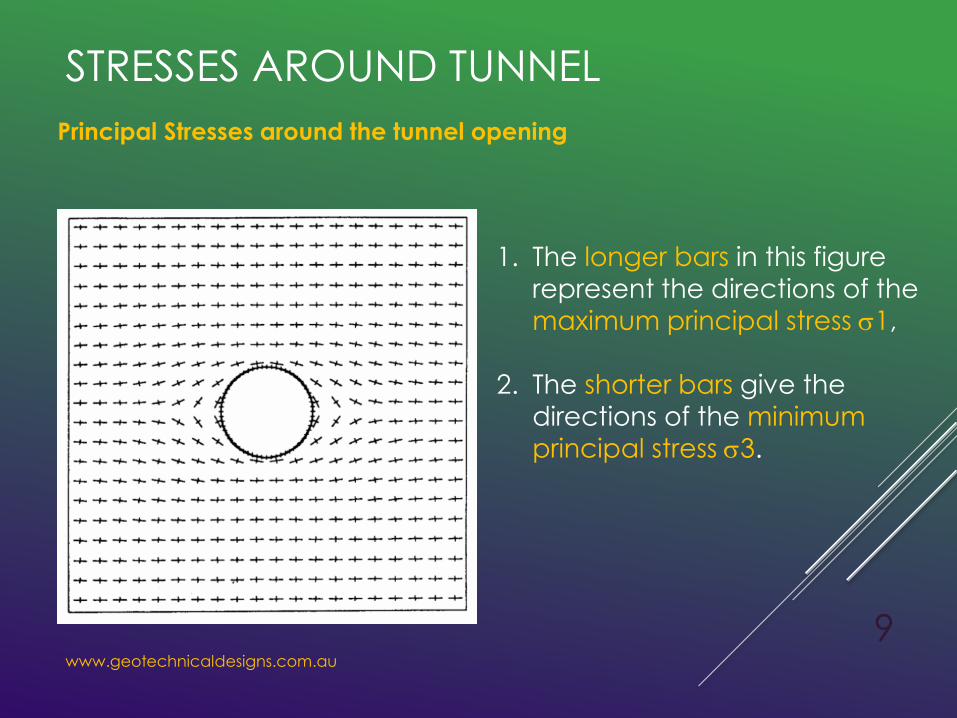
Principal Stresses around the tunnel opening
STRESSES AROUND TUNNEL
1. The longer bars in this figure
represent the directions of the
maximum principal stress 1,
2. The shorter bars give the
directions of the minimum principal stress 3.
www.geotechnicaldesigns.com.au
10
NUMERICAL ANALYSIS –
STRESSES AROUND TUNNEL
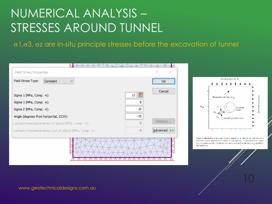
1,3, z are in-situ principle stresses before the excavation of tunnel

www.geotechnicaldesigns.com.au
11
NUMERICAL ANALYSIS –
STRESSES AROUND TUNNEL1,3, z are in-situ principle stresses before the excavation of tunnel
13
z
www.geotechnicaldesigns.com.au
12
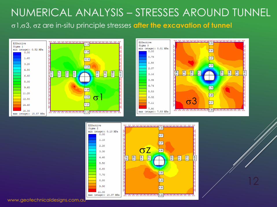
NUMERICAL ANALYSIS – STRESSES AROUND TUNNEL1,3, z are in-situ principle stresses after the excavation of tunnel
1 3
z

www.geotechnicaldesigns.com.au
13
NUMERICAL ANALYSIS – STRENGTH FACTOR
Strength factor represents the ratio of available rock mass strength to
induced stress at a given point.
There is a large zone of
overstress surrounding the
tunnel. All the rock with the
contour marked around 1
will fail if left unsupported.
Observe the zone of plastic
yielding (X = shear failure, O
= tensile failure) around the
excavation. Notice that the
yielded zone roughly
corresponds with the zone of
strength factor about SF = 1
www.geotechnicaldesigns.com.au
14
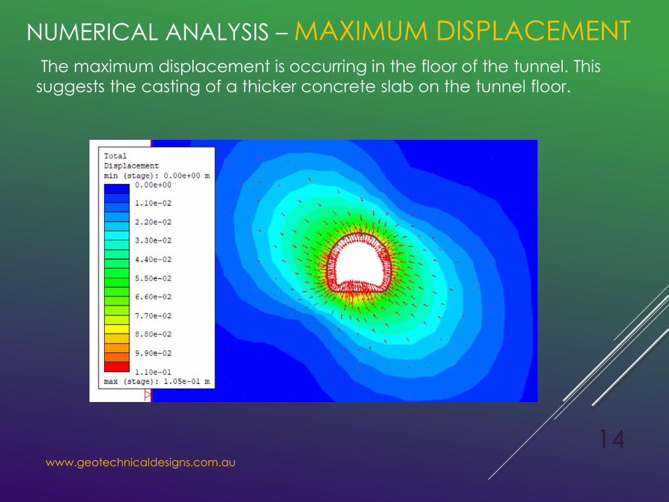
NUMERICAL ANALYSIS – MAXIMUM DISPLACEMENTThe maximum displacement is occurring in the floor of the tunnel. This
suggests the casting of a thicker concrete slab on the tunnel floor.

www.geotechnicaldesigns.com.au
15
CONCLUSIONS
In this presentation I have talked about in-situ stresses in rock at certain
depth. If a tunnel is excavation in this present stresses, there will be
redistribution of stresses around the tunnel opening. Some where there will
be release of stresses (at opening) and somewhere there will be
concentration of stresses.
Due to this the strength of rock mass around the opening reduces below
the available in-situ stresses and therefore large deformations will occur
around the opening and now here the support system comes into picture
to support the tunnel from collapsing.
To restrict the deformation to certain level we need support system, which
we will cover in another presentation.

www.geotechnicaldesigns.com.au
16
THANK YOU
FOR
YOUR PRECIOUS TIME