in mea’s distribution system - german-thai...
TRANSCRIPT

Smart Substationsin MEA’s Distribution System
Pichit Jintagosonwit

Uses information technologies to improve how electricity travels from power plants to consumers
Allows consumers to interact with the grid
Integrates new and improved technologies into the operation of the grid resulting in new services and functions
Electrical Infrastructure + Intelligence Infrastructure
Smart Grid
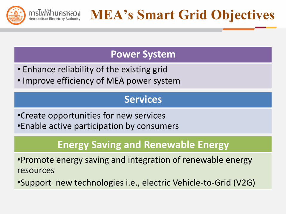
MEA’s Smart Grid Objectives
Power System
• Enhance reliability of the existing grid• Improve efficiency of MEA power system
Services
•Create opportunities for new services•Enable active participation by consumers
Energy Saving and Renewable Energy
•Promote energy saving and integration of renewable energy resources
•Support new technologies i.e., electric Vehicle-to-Grid (V2G)

MEA’s Smart Grid RoadmapStage 1
2012– 2016
Laying the Foundations
Stage 2
2017 – 2021
Large Scale Implementation
Stage 3
2022 – 2026
Ultimate Stage
Power System
Implement Substation Automation based on IEC61850 for existing substations
40 substations 100 substations 100% (approx. 170 substations)
Implement Distribution Management System
30% of service area 60% of service area 100% of service area
Employ outage monitoring system in HV and MV Extend outage monitoring system to LV
Initiate self-healing capability in HV and MV for some areas.
Expand self-healing capability in HV and MV to
cover the entire service area
Implement asset management to reduce operation and maintenance costs
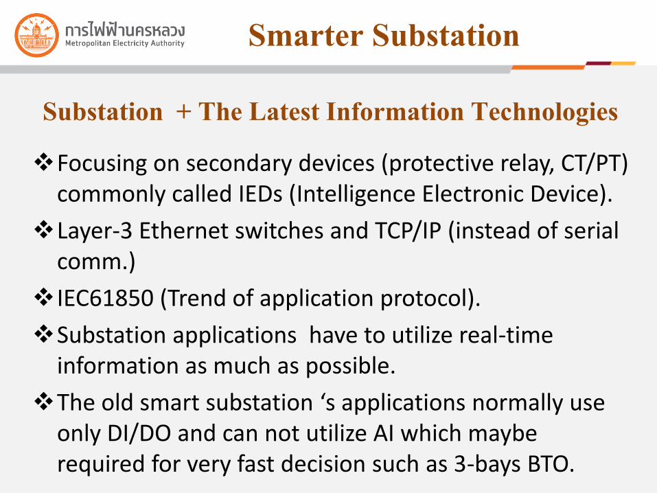
Smarter Substation
Focusing on secondary devices (protective relay, CT/PT) commonly called IEDs (Intelligence Electronic Device).
Layer-3 Ethernet switches and TCP/IP (instead of serial comm.)
IEC61850 (Trend of application protocol).
Substation applications have to utilize real-time information as much as possible.
The old smart substation ‘s applications normally use only DI/DO and can not utilize AI which maybe required for very fast decision such as 3-bays BTO.
Substation + The Latest Information Technologies

IEC61850 Messaging (1)
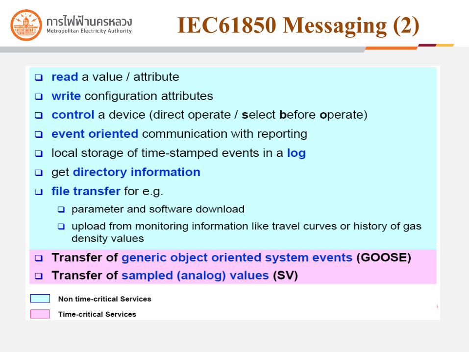
IEC61850 Messaging (2)

3-Bays BTO Function (1)
27
L1 L2
BCA
BCB
BC
DS2A
DS2B
DS1A
DS1B
Auto
Bus A
Bus B
2
Termainal Station 1
Termainal Station 2
Subtation
3 Bays-BTO
Do not Close due to Tr.2 may be overload
1
2

3-Bays BTO Function (2)
27
L1 L2
BCA
BCB
BC
DS2A
DS2B
DS1A
DS1B
Auto
Bus A
Bus B
3
4
2
Termainal Station 1
Termainal Station 2
Subtation
3 Bays-BTO
1
2

Smart Substation for Smart Grid
Supporting future grid applications in scale of bay-level response time (4ms by native GOOSE, super fast for grid level) by using VLAN across WAN.
GOOSE/UDP is coming for across network via gateways /firewalls.
Making us can share communication infrastructure such as fiber-optic cores. For Example ,in the past, we had to use dedicated cores and PLCs for LTF (Line Transfer Function between substations)
Because of TCP/IP, Switch, IEC61850 technologies

LTF (1)
Inline Substation
Managed Switch
IED withLTF function
Open-loop Substation
IED with LTF function
Managed Switch
IP Network

LTF (2)
27
L1-A L2-A
BCA-A DS-B
L1-B L2-B
BCB-A
BC-A
DS2A-A
DS2B-A
DS1A-A
DS2B-A
Inline Substation
Auto
27 Trip
2
3 4
DS1-B DS2-B
From Terminal Station 1
From Terminal Station 2
Open-loop Substation
Delay of 0.2 Sec
1

CCU#2
Station bus
Station Gateway
CCU#1HMI
Processinterface Processinterface Processinterface
Bay controlProtection& Control
Protection& Control
Protection& Control
Bay control
SCADA
TDS
Protective Relay BCU
Consolidation Concept
Smart Substation > Substation Automation

14
Typical System Topology
HMI
EngineeringPortable MMI
Main 21/21N,27/59, 79, 50BF
67/67N,27/59 50BF+ BCU
Line Bay
Main87
50/51, 50/51N, 50BF+BCU
Trans. Bay
50/51, 50/51N, 50BF+BCU
BS/BC. Bay
Main 21/21N,27/59,79,50BF
67/67N,27/59 50BF+ BCU
Line Bay
Main 87
50/51, 50/51N, 50BF+BCU
Trans. Bay
Gateway With Firewall(CGW)
DCC
115/69kV
Station Computers
Switch Switch Switch Switch Switch
Switch Switch
TDS
GPS
CCU#1 CCU#2
LAN A
LAN B
Station Level
Bay Level

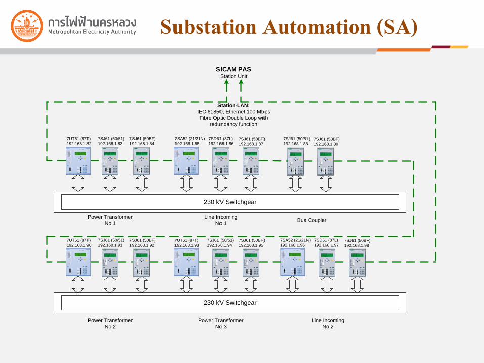
Substation Automation (SA)
Substation Automation (SA)
230 kV Switchgear
Station-LAN:
IEC 61850; Ethernet 100 Mbps
Fibre Optic Double Loop with
redundancy function
Power Transformer
No.1
Line Incoming
No.1
230 kV Switchgear
SICAM PASStation Unit
7SJ61 (50/51)
192.168.1.83
7SJ61 (50BF)
192.168.1.84
7SD61 (87L)
192.168.1.867SJ61 (50BF)
192.168.1.87
7SA52 (21/21N)
192.168.1.85
7UT61 (87T)
192.168.1.82
Bus Coupler
7SJ61 (50/51)
192.168.1.887SJ61 (50BF)
192.168.1.89
Power Transformer
No.2
Power Transformer
No.3
Line Incoming
No.2
7SJ61 (50/51)
192.168.1.91
7SJ61 (50BF)
192.168.1.92
7UT61 (87T)
192.168.1.90
7SJ61 (50/51)
192.168.1.94
7SJ61 (50BF)
192.168.1.95
7UT61 (87T)
192.168.1.93
7SD61 (87L)
192.168.1.977SJ61 (50BF)
192.168.1.98
7SA52 (21/21N)
192.168.1.96

SA Physical Allocation
• 2 Station Computers• 2 Man Machine Interface Servers • 2 Operator Man Machine Interface (HMI)• Engineering Work Station and Fault Evaluation System• Communication Gateway (CGW)• Time and Date Server (TDS)• Station LAN• Ethernet Switches
• Main and Backup Protection Relay (87L, 21, 87B, 87T, 67, 50/51,…) • Backup Protection (Breaker Failure Protection : 50BF)• Bay Control Unit (BCU)
Process Level• Conventional Type CT/VT• Conventional Hardwire Connection

Process Level: Hard Wiring
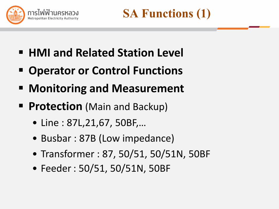
SA Functions (1)
HMI and Related Station Level
Operator or Control Functions
Monitoring and Measurement
Protection (Main and Backup)
• Line : 87L,21,67, 50BF,…
• Busbar : 87B (Low impedance)
• Transformer : 87, 50/51, 50/51N, 50BF
• Feeder : 50/51, 50/51N, 50BF

SA Functions (2)
Automatic Functions• High Speed Automatic Transfer Scheme
• Voltage Selection
• Automatic Load Shedding
• Automatic Load Restoration
• Interlocking
• Breaker Failure Protection
• Rate-of-Change Calculations and Alarming for Selected Analog Input Variables
• Heartbeat Function
• Maintenance of TRIP Counters for Breakers
• Breaker Operating Time Checks

SA Functions (3)
Local/Remote Control and Monitor
Voltage and Var Control
Trend Records
Events, Alarm and Disturbance Records
Fault Location

Implementation of SA Chidlom Terminal Station
Substation Automation Systems
Base on IEC 61850
Energized on May 09, 2009
22

Indoor Type Substation
23
Chidlom Terminal Station Building

Primary Equipment : 230kV GIS
24

Transformer : 300 MVA
25

Primary Equipment : 69kV GIS
26
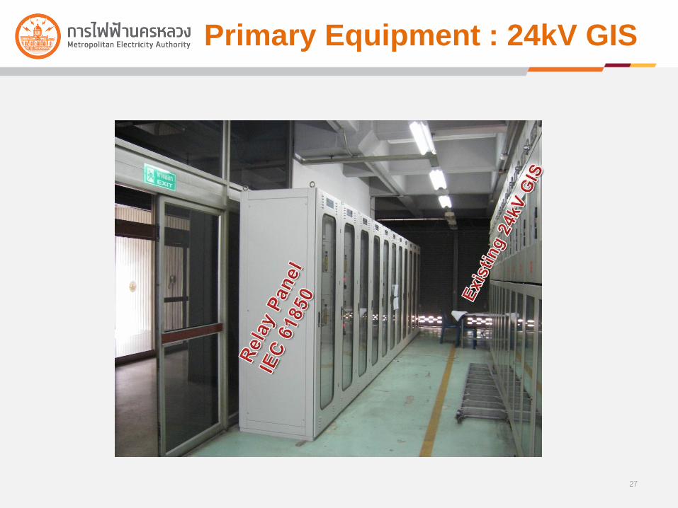
Primary Equipment : 24kV GIS
27

Mimic Board and HMI
28

Station Computers
Station Computers
• 2 Station Computers
• 2 Man Machine Interface
Servers
• 2 Operator Man Machine
Interface (MMI)
• Engineering Work Station
• Communication Gateway
(CGW)
• Time and Date Server (TDS)
• Station LAN
• Ethernet Switches
29

Bay Level : Relay & BCU Panel
30

IEC61850 Experiences
CCU#2
Station bus
Station Gateway
CCU#1HMI
Processinterface Processinterface Processinterface
Protection& Control
Protection& Control
Protection& Control
SCADA
TDSOur protective relay handles automatic,control, interlocking, metering andprotection functions, but actually anyprotective relay has its limitation andalso differ from other vendors. e.g.logic-gate capacity, processing time andfunctionalities giving us severaldifficulties and deviations from ourtechnical specification.
Protection& Control
Protection& Control
The main point is that we have torequire specific protective relaysfor sparing due to it is almostimpossible for replacing by other-vendor in no time.

IEC61850 Experiences To maintain SA as easy as possible easily changing a relay with the minimal time. easily procuring a relay as spare from multi-vendors. needing the minimal number of maintenance guys and knowledge for maintaining.
Purposed Solutions allocating the fewest functions to each device as much as possible. purchasing size of a relay as small as possible. More bigger more difference of
capabilities among vendors such as a number of reports , a number of logic gates , a number of CSWI , number of physical I/O . Consequently, in the case of the full capacity implementation of a relay, It may not be able to put all same functions of the relay to other relay of other vendor resulting in maintenance difficulties.
Preparing function compatible list (FCL) including configuration files for purchasing any spare relays

Function Compatible List (1)
Station Level
Bay Level
A B C
A
A B C
B
A B C
C

Function Compatible List (2)
Station Level
Bay Level
A B C
A
A B C
B
A B C
CMain Function Main Function Main Function
Sub Function Sub Function Sub Function

Number of Physical I/Os
Main Protection
Equipment Status by GOOSE
Back-up Protection
Equipment Status by Hardwiring
Main Protection Back-up Protection
Equipment Status by Hardwiring
Misunderstanding, proposed protective relays from a contractor may have not enough physical I/Os to supportprotection schemes with high reliability resulting in changing new protective relays and causing a project delay. Duringissue of the technical specification, MEA has found that one of the most important points is to specify minimal numberof physical I/O of any protective relay to support the required functionality making bidders have the clearest view ofwhat protective relays be proposed to MEA. Figure 2 shows two solutions that can do same functions, but they havedifferent reliability level from serial and parallel arrangements.

Sim Box
Plant Simulation Box
New Control Cable
Switchgear still is on service
During the installation process of the SA devices in an existing substation, all the automatic, control and meteringfunctions have to be tested to assure correct functioning when put in services. Due to shutdown time may be not longenough or difficult to fully perform all equipment tests causing project delay. Consequently, MEA has to use plantsimulation boxes acting as substation equipments for testing all functions shown as Figure 4. Therefore the neededshutdown time of such substation is as short as the required time for checking equipment connections whether arecorrect

Benefits (1)
Standardization
Natural Resources Reduction with
Modern Networking Technology
Cost Reduction
• More Vender Competition
• More Intelligence Functions
• One Time Investment
Commissioning and Maintenance Time Saving
37
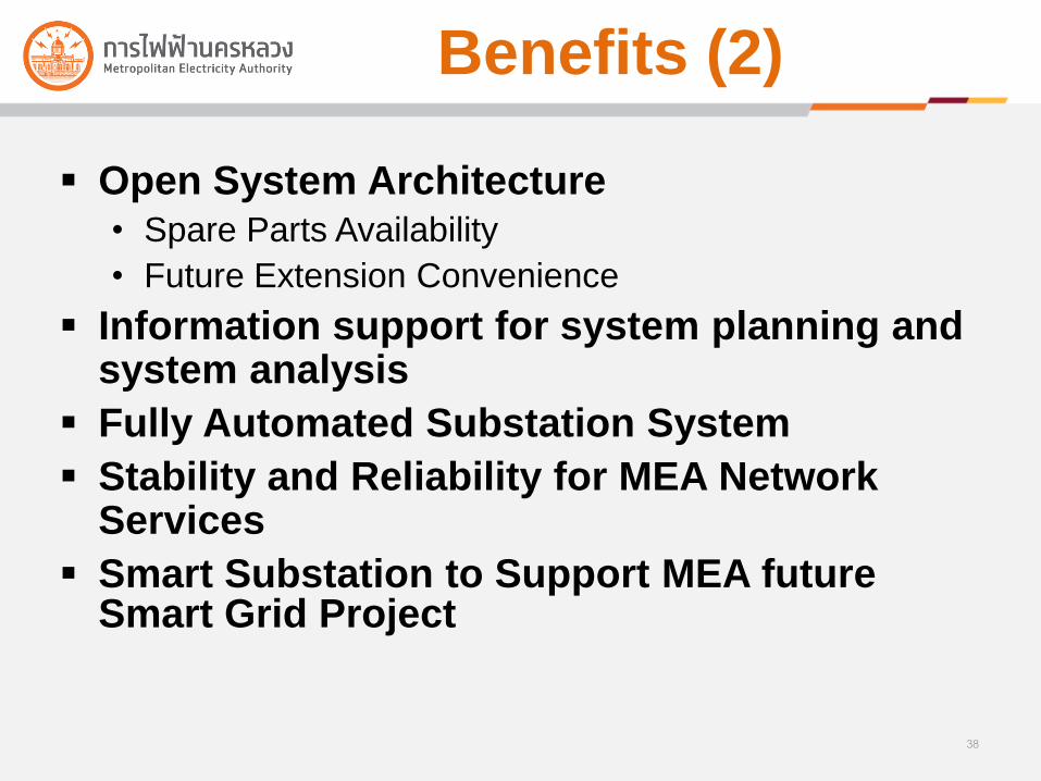
Benefits (2)
Open System Architecture• Spare Parts Availability
• Future Extension Convenience
Information support for system planning and system analysis
Fully Automated Substation System
Stability and Reliability for MEA Network Services
Smart Substation to Support MEA future Smart Grid Project
38
Thank you for your attention.