improving the fatigue resistance of thermite railroad rail...
TRANSCRIPT

1
Improving the FatigueResistance of ThermiteRailroad Rail Weldments
F. V. LawrenceY-R. ChenJ. P. Cyre

2
Outline
! Fatigue problems with thermite welds
! Improving the rail head
! Improving the rail web and base

3
Metallic Fatigue
A.M. Zarembski – Bulletin 673, 1979, Volume 80 of AREA proceedings
ACELA

4
Rolling contact fatigue
Thermite Weld
Rail
B
H
W
Railroad car wheelmoving over railcauses fatigue tooccur in both the railhead and base.

5
Fatigue crack initiation sites
Internal Fatigue Crack
Rail Head
Rail Web
Web-to-base Fillet
Fatigue Crack at Weld Toe in Fillet
Rail Base
Fatigue Crack at Weld Toe in Base
! ≈ 40% of all servicefailures are due tothermite field welds.
! ≈ 10% of allderailments are dueto broken fieldwelds.

6
Fatigue crack in rail head
Internal fatigue crack initiation in rail head

7
Fatigue crack in rail base
Cold Lap
Site of crackinitiation
Limit of fatiguecrack growth

8
Thermite weld service failures
0.0%
5.0%
10.0%
15.0%
20.0%
25.0%
30.0%
35.0%
Base Web-basefillet
Web Head-webfillet
Head ?
Location
Record of 244 service failures on a Class 1 railroadinvolving thermite field welds.

9
Service failures or “markouts”?
! Most field-weld service failuresoriginate at web or base.
! But defects detected and removedfrom the rail head before a servicefailure can occur (“markouts”)exceed service failures by 2:1!

10
Implications
! Fatigue cracks in the web and base areless frequent but are the principalcause of service failures since they aredifficult to detect. Crack initiationoccurs at external stress concentration.
! Fatigue cracks in head are morefrequent but are generally removed.Crack initiation occurs at internal stressconcentration.

11
Outline
! Fatigue problems with thermite welds
! Improving the rail head
! Improving the rail web and base

12
Porosity types
Shrinkage Gas (Spherical)
Thermite welds studied contain about 1.5% shrinkage porosity.

13
Porosity initiates fatigue
Formation of shells in tangent trackat interdendritic shrinkage porosity.
Running surface.
Odario 1992

14
Interdendritic shrinkage porosity

15
Possible solution?
! Eliminate weld metal! (?)
! Developed a modified thermitewelding process called “SqueezeWelding” in which ends of joint forcedtogether to expel most of the thermiteweld metal.

16
Squeeze welding
Force Force
Rail Cross-section
Expelled Imputities
FinalWeldThickness
Rail EndsMoved TogetherWhile WeldMetal StillMolten

17
Weld longitudinal-sections
Standard Squeezed
WM
HAZ
BM
Fry 1992

18
Laboratory test results
10
100
1000
104 105 106 107 108
Withee - Squeezed
Liu - Squeezed/Vibrated
Liu - SqueezedLiu - Vibrated
Liu - Standard
Withee - Vibrated
Withee - Standard
Max
imum
Str
ess,
S max
(MP
a)
Fatigue Life, Nf(cycles)
Fatigue behavior of small specimens taken from head ofweld shows some improvement.
Withee 1998
87 mm
19 mm
9.27 mm
R 208 mm19 mm
6.35 mm

19
But distribution unchanged!
0.0
0.2
0.4
0.6
0.8
1.0
100 101 102 103 104 105
Standard Weld
Squeezed Weld
Vibrated Weld
Cu
mu
lativ
eP
rob
ab
ility
Pore Size, area (µm2)
size range of poresinitiating failureimputed fromSEM images
Pore size distribution unchanged!Withee 1998

20
Largest pore size controls!
1.0
10.0
100.0
104 105 106 107
Standard Weld (C)Squeezed Weld (B)Vibrated Weld (D)Regression Analysis
Initi
alS
tres
sIn
tens
ityF
acto
r,K o
(MP
a*m
1/2)
Fatigue Life, Nf(cycles)
B1
C1C5
D5B4
B3
B2
13
Withee 1998
Single relation for all treatments depending only on pore size(and applied stress).
87 mm
19 mm
9.27 mm
R 208 mm19 mm
6.35 mm

21
Implications
! Reducing the size of the largestpores and/or the volume of weldmetal should increase in the(average) fatigue life.
! Largest pore per unit volume(porosity) and the volume of weldmetal jointly determine the fatiguestrength.

22
Theoretical study
p
Σ(t)
(t)
Fry 1995

23
Stress history experienced
Str
ess
MP
a)

24
Fatigue occurs at critical depth
Fatiguedamageparameter
Worst depth
Worstlocations onpore
Dep
thbe
low
runn
ing
surf
ace,
Y(m
m)
No residual stress Considering residual stress
Fry 1995

25
Effects of pore shape?
2
0
0.5
1
1.5
2
2.5
3
3.5
0 0.5 1 1.5 2 2.5
2
4
6
8
10
152025
3040
50
60
72
λY
/λZ
Ratio of pore's longitudinal and transverse axes,λX
/ λZ
FBY
PCV
FBX
SpherePCHFBZ
PCT
Detail Fracture
Vertical Split Head
Shelling
RAHELS Predictions
FavorsDetailfracture
Favors verticalsplit-head
Favorsshelling
Fry 1995

26
Model predictions
! Critical depth for fatigue crackinitiation (≈ 15mm) determined bywheel-contact-induced residualstresses.
! Model predicted that shelling, verticalsplit heads and detail fracture couldall initiate at shrinkage poresdepending upon the pore shape.

27
Central portion of weldmentmachined and ground flat to12.7 mm thickness. Stepped penetrameter.
specimen film
New measurement technique
Chen 2000

28
L1
Typical radiograph
!?!
Difference incontrast due tomicro-porosity(shrinkageporosity.
Porosity notuniformlydistributed!
Chen 2000

29
Radiographs of field welds
F1 F2 F3

30
0.52% 1.72%interface
Optical determination of porosity

31
25000
27000
29000
31000
33000
35000
37000
39000
0 500 1000 1500 2000 2500 3000 3500 4000
Distance
Measuredchanges ingrey scale inphotoshop.
Penetrameter with 0.11 mm steps indicateat least 1% sensitivity
F1
BM WM
0% 0.9% porosity
Radiographic image density

32
0
0.2
0.4
0.6
0.8
1
1.2
1.4
B-3 B-4 A-6 A-7 A-8 A-1 L-1 B-1 A-2 A-3
Po
rosi
ty(%
)
Porosity in 10 thermite welds
Average porosity in 10 “markouts” varies considerably!
Chen 2000
33
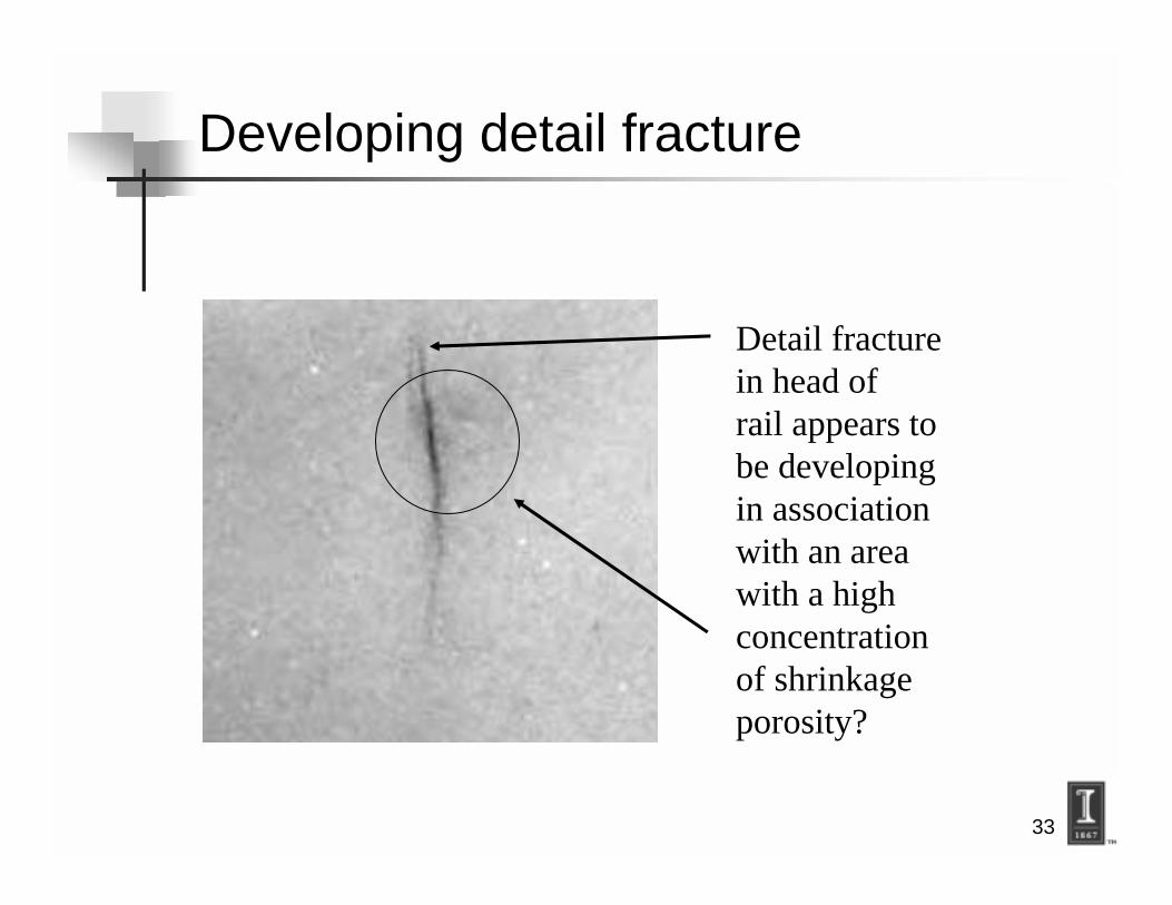
Developing detail fracture
Detail fracturein head ofrail appears tobe developingin associationwith an areawith a highconcentrationof shrinkageporosity?

34
Conclusions
! Large variation in porosity from weld toweld. Porosity not uniformlydistributed.
! Porosity clusters at weld centerlinefrequently seen. Fatigue cracks inhead often associated with associatedwith porosity clusters.
35
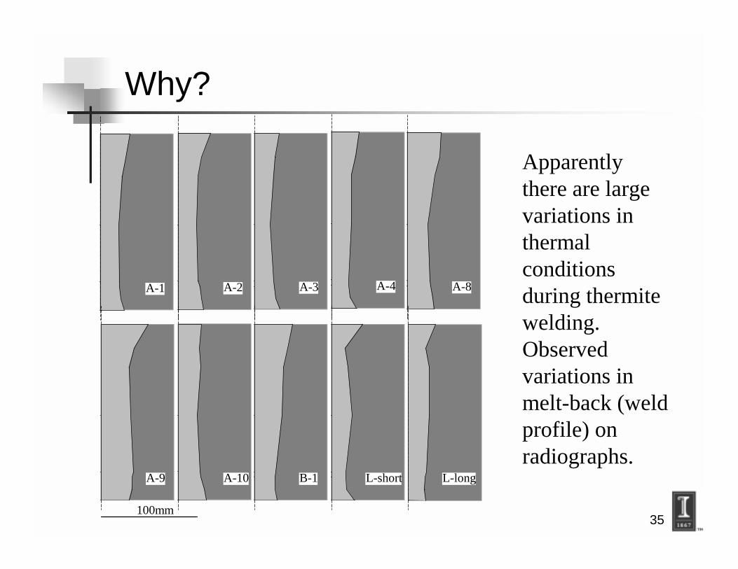
Why?
A-1 A-2 A-3 A-4 A-8
A-9 A-10 B-1 L-short L-long
100mm
Apparentlythere are largevariations inthermalconditionsduring thermitewelding.Observedvariations inmelt-back (weldprofile) onradiographs.

36
Outline
! Fatigue problems with thermite welds
! Improving the rail head
! Improving the rail web and base
37
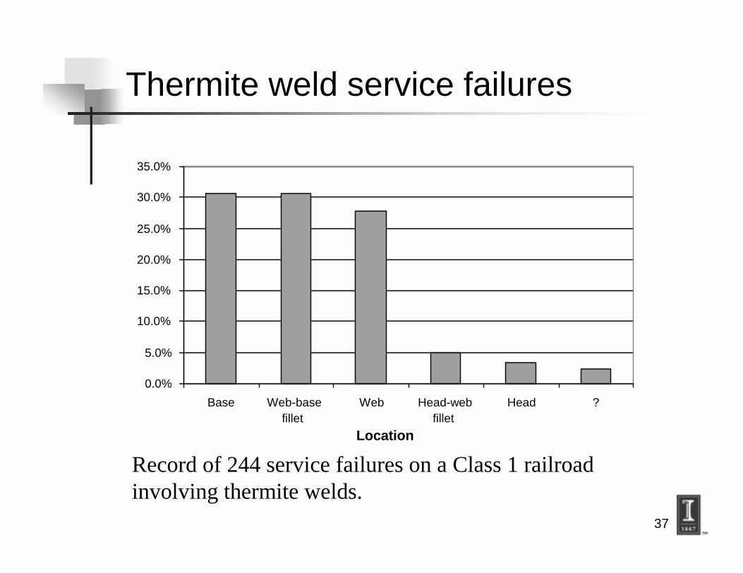
Thermite weld service failures
0.0%
5.0%
10.0%
15.0%
20.0%
25.0%
30.0%
35.0%
Base Web-basefillet
Web Head-webfillet
Head ?
Location
Record of 244 service failures on a Class 1 railroadinvolving thermite welds.

38
Web-to-base fillet !?!
! Why does this happen ?????
! Answer:! Residual stresses!
! Weld toe geometry!! Flank angle.! Cold laps.

39
Webster et al.
Residual stresses
Neutral Axis
Critical locations:• Web-to base fillet• Rail base
Compression Tension

40
Weld toe flank angle
≈ 85̊ Flank Angle

41
Weld toe geometry
Toe Radius (r)
Roughness (R)
Flank Angle
Weld Metal Base Metal
(θ)
Fatigue Severity = 1+0.27 tanθ0.25 t
r
1+0.1054Su R( )−1
Improve by:
• Flank angle↓
•��������� ↑
•���������↓

42
Current Orgo-thermit mold profiles
A-A
B-B
C-C D-D
E-E
4530
A-A
AA
BB
CC
DD
MoldRail and weld
Measured profiles ofOrgo-thermit molds

43
Modified Orgo-thermit mold profiles
Suggestedmodifications toOrgothermitmolds
AA
BB
CC
DD
Modified Current

44
Nature of critical defects
0.0% 5.0% 10.0% 15.0% 20.0% 25.0% 30.0% 35.0%
Cold Lap
Slag
Hot Tear
Porosity
Lack of Fusion
Columnar Grains in Head
Grind Burn
Hot Pull-apart
Inclusion in Head
Sand burn in
?
Analysis of 244 service failures on a Class 1 railroadinvolving thermite welds.

45
Cold laps - Dimitrakis
Cold lap No cold lap
Cold laps greatly reduce the fatigue life of a weldment

46
Cold laps at thermite weld toe
Cold Lap
Base Metal

47
Weld toe cold laps
LoadingDirection
D
Weld Metal
Base MetalHeat Affected Zone
Weld Toe LocationWithout Cold-Lap Defect
Curved PathVertical Path
θ
r
φ

48
Effect of cold laps
Condition Percentage of Fatigue Life
Flank angle (θ) = 30Þ 100%
Flank angle (θ) = 45Þ 56%
Flank angle (θ) = 60Þ 44%
Cold lap depth (D) = 0 100%
Cold lap depth (D) = 1mm 20%
Cold lap depth (D) = 2mm 15%

49
Causes of cold laps
! Gap between mold and rail in thecritical web-to-base fillet area.
! Inadequate melt back causingincomplete fusion at the weld toe?

50
Variations in melt-back
A-1 A-2 A-3 A-4 A-8
A-9 A-10 B-1 L-short L-long
100mm
Melt backvariesconsiderablyin thelocation ofthe web-tobase fillet

51
Melt back dimensions
0 0.1 0.2 0.3 0.4 0.5 0.6 0.7 0.8 0.9 1
6
5
4
3
2
1
0
Hei
gh
to
fR
ail(
in.)
Length of Melt Back (in.)
Weld Sample #2
Weld Sample # 3
Weld Sample #1

52
Melt back at web-to-base fillet
0
10
20
30
40
50
26-30 31-35 36-40 41-45 46-50 51-55 56-60 61-65 66-70
Melt-back width (mm)
Collar width defined by mold
Bad! Good!

53
UIUC Experimental Program
UIUC modified 1”thermiteweld molds are usedwith a 1.4” rail gap.Mold sealed at weld toewith refractory paste.
And: Reduced flankangle!
Standard 1” thermiteweld: Large flank angleand cold laps.
Rail Rail
Weld MetalMelt back

54
UIUC Experimental Program
Luttingpaste fromRailtech.
Sealing pastefrom Railtechw/ BrazingFlux.

55
UIUC Experimental Program
Uni Ram Blurefractory paste.
Leecote moldwash and UniRam Blurefractory paste.

56
Weld Fabrication
1
3
4
65
2

57
Fatigue testing
Standard 4-point bending test.

58
Modified Weld Specimen #28
Crack initiationpoints
Limit of fatigue crack growth

59
Effect of modifications
Cold lapformationbeyondsealingpaste

60
Standard weldments
100
1,000
10,000
1,000 10,000 100,000 1,000,000 10,000,000
Cycles to Failure, N f
Process A
Process B
Process C
Process D
TAMU
1
3

61
100
1,000
10,000
1,000 10,000 100,000 1,000,000 10,000,000
Cycles to Failure, N f
Process A
Process B
Process C
Process D
Modified UIUC
TAMU
UIUC experimental welds
1
3

62
100
1,000
10,000
1,000 10,000 100,000 1,000,000 10,000,000
Cycles to Failure, N f
Process A
Process B
Process C
Process D
Modified UIUC
TAMU
UIUC experimental welds
1
3

63
Summary - Head failures
! Head failures caused by internaldefects notably porosity and highconcentration areas of porosity.
! Thermal conditions duringsolidification may cause oneweldment to be good and another tobe bad?

64
Summary - Web-base failures
! Web and base failures aggravated bysevere external geometry and coldlaps.
! Thermal conditions duringsolidification play a role in web-basefatigue problems?
! Fatigue life can be increased bymodifications of external weldgeometry.