improving placement under the constant delay model kolja sulimma 1, ingmar neumann 1, lukas van...
TRANSCRIPT

Improving Placement under the Constant Delay Model
Kolja Sulimma1, Ingmar Neumann1, Lukas Van Ginneken2, Wolfgang Kunz1
1EE and IT DepartmentUniversity of Kaiserslautern
2Magma Design AutomationCupertino, CA, USA
contact: [email protected]
2
Overview
Conventional Delay Models detailed vs. abstract delay models timing driven placement and the critical path
problem Constant Delay Model
introduction placement under the constant delay model fast and exact area computation
Experimental Results

3
Delay of a CMOS Gate non-linear depends on many variables
load capacitance input slew rate temperature supply voltage interconnect
resistance crosstalk inductance?
detailed tabular models can be used for timing analysis
to irregular to guide the synthesis process
load capacitance
gate delay

4
Unit Delay Model assumes all gates have
the same delay independant of load,
etc. performes astonishingly
well not accurate enough in
the deep sub micron age
load capacitance
unit delay model
gate delay

5
Linear Delay Model linear delay/load
dependancy relatively accurate fit widely used for timing
driven tool flows linear slew effects are
commonly added to improve the model
load capacitance
linear delay model
gate delay

6
Placement with Linear Delay Model
arrange gates of fixed area to minimize the circuit delay
moving a gate modifies the length (and capacitance) of adjacent wires
tcritical

7
Placement with Linear Delay Model
arrange gates of fixed area to minimize the circuit delay
moving a gate modifies the length (and capacitance) of adjacent wires
tcritical

8
Placement with Linear Delay Model
arrange gates of fixed area to minimize the circuit delay
moving a gate modifies the length (and capacitance) of adjacent wires
tcritical

9
Placement with Linear Delay Model
arrange gates of fixed area to minimize the circuit delay
moving a gate modifies the length (and capacitance) of adjacent wires
tcritical

10
Placement with Linear Delay Model
arrange gates of fixed area to minimize the circuit delay
moving a gate modifies the length (and capacitance) of adjacent wires
tcritical
11
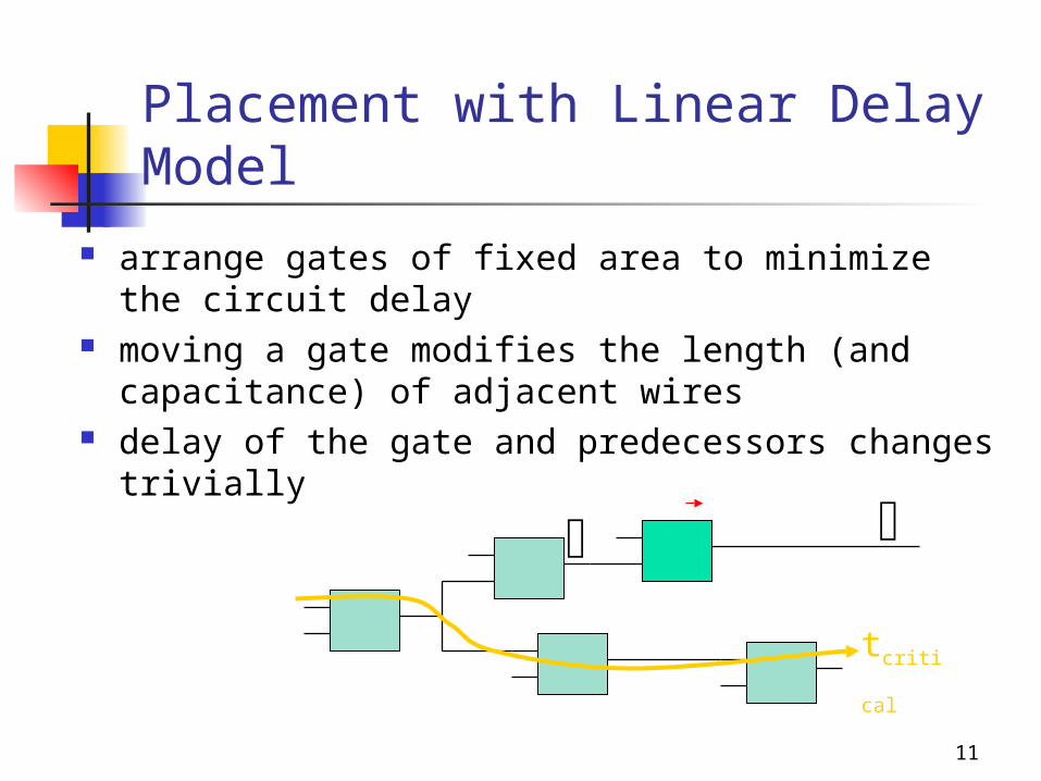
Placement with Linear Delay Model
arrange gates of fixed area to minimize the circuit delay
moving a gate modifies the length (and capacitance) of adjacent wires
delay of the gate and predecessors changes trivially
tcritical

12
Placement with Linear Delay Model
arrange gates of fixed area to minimize the circuit delay
moving a gate modifies the length (and capacitance) of adjacent wires
delay of the gate and predecessors changes trivially
tcritical

13
Placement with Linear Delay Model
arrange gates of fixed area to minimize the circuit delay
moving a gate modifies the length (and capacitance) of adjacent wires
delay of the gate and predecessors changes trivially
tcritical

14
Placement with Linear Delay Model
arrange gates of fixed area to minimize the circuit delay
moving a gate modifies the length (and capacitance) of adjacent wires
delay of the gate and predecessors changes trivially
tcritical

15
Placement with Linear Delay Model
arrange gates of fixed area to minimize the circuit delay
moving a gate modifies the length (and capacitance) of adjacent wires
delay of the gate and predecessors changes trivially
but what about the critical path?
? tcritical

16
Placement with Linear Delay Model
arrange gates of fixed area to minimize the circuit delay
moving a gate modifies the length (and capacitance) of adjacent wires
delay of the gate and predecessors changes trivially
but what about the critical path?
?tcritical

17
Placement with Linear Delay Model
arrange gates of fixed area to minimize the circuit delay
moving a gate modifies the length (and capacitance) of adjacent wires
delay of the gate and predecessors changes trivially
but what about the critical path?
? tcritical
18
? tcritical
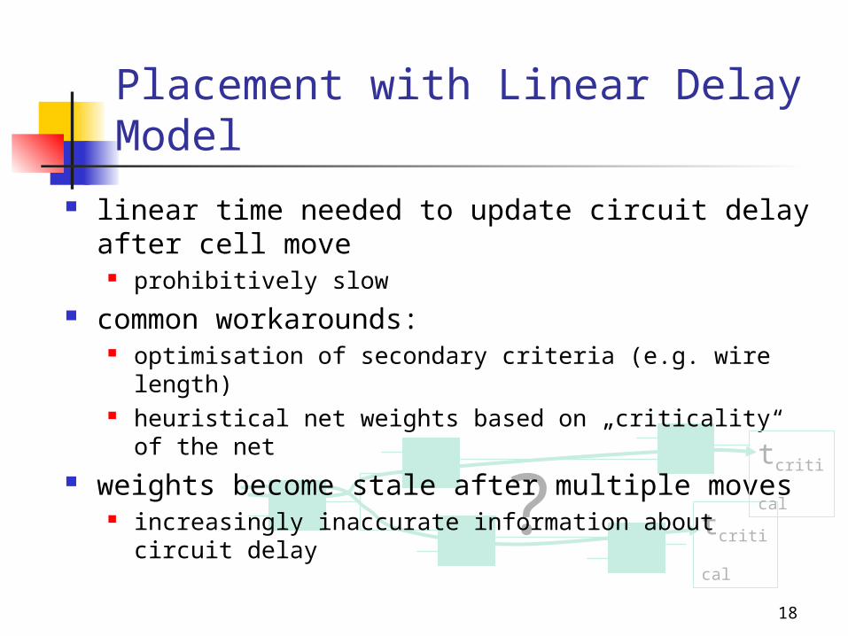
Placement with Linear Delay Model
linear time needed to update circuit delay after cell move
prohibitively slow common workarounds:
optimisation of secondary criteria (e.g. wire length) heuristical net weights based on „criticality“ of the net
weights become stale after multiple moves increasingly inaccurate information about circuit delaytcritical
19
Constant Delay Model
the models presented so far modeled the delay of a given gate implementation of constant size
Constant Delay Model models the gate size required to meet a given constant gate delay
requires a cell library that provides many cell sizes for each logic function it implements, or a cell that allows to size cells continously

20
Constant Delay Model the delay of a gate is assumed to
be constant
load capacitance
modeled delay

21
Constant Delay Model the delay of a gate is assumed to
be constant for any load capacitance a certain
gate size is required to achieve this delay
load capacitance
modeled area
modeled delay

22
Constant Delay Model the delay of a gate is assumed to
be constant for any load capacitance a certain
gate size is required to achieve this delay
this gate size ideally depends linearly on the load capacitance
load capacitance
modeled area
modeled delay
C
A

23
Constant Delay Model the delay of a gate is assumed to
be constant for any load capacitance a certain
gate size is required to achieve this delay
this gate size ideally depends linearly on the load capacitance
if there is only a fixed set of gate sizes the actual area will deviate from the model
load capacitance
actual area modeled area
modeled delay

24
Constant Delay Model the delay of a gate is assumed to
be constant for any load capacitance a certain
gate size is required to achieve this delay
this gate size ideally depends linearly on the load capacitance
if there is only a fixed set of gate sizes the actual area will deviate from the model
this causes the actual delay to deviate from the model
load capacitance
actual areamodeled areaactual delaymodeled delay

25
Constant Delay Model the delay of a gate is assumed to be
constant for any load capacitance a certain
gate size is required to achieve this delay
this gate size ideally depends linearly on the load capacitance
if there is only a fixed set of gate sizes the actual area will deviate from the model
this causes the actual delay to deviate from the model
fortunately, this effect is alleviated by load effects on the preceeding gates
actual area modeled areaactual delay including preceeding stagemodeled delay

26
Constant Delay Model: Placement
find a placement minimising the circuit area for a given circuit delay
note: ideally all cells remain critical during the placement process avoids critical path problem
we propose a new approach based on net weights that measure exactly how a local change of the wire capacitance
effects the overall circuit area can be computed efficiently in advance remain valid throughout the placement process

27
i
Constant Delay Model: Circuit Area
gate area Ai increases linearly with the load capacitance Ci seen at gate i.
i
iii C
ACA
i

28
Constant Delay Model: Circuit Area
the input capacitance Cij of any input j of gate i increases linearly with the load capacitance
i
i
ijiij C
CCC
j
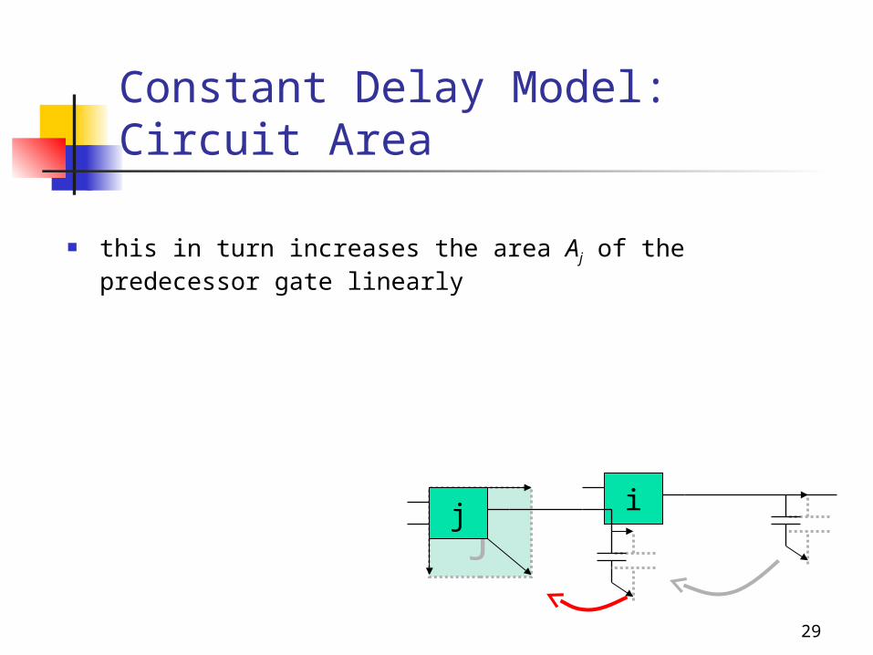
29
Constant Delay Model: Circuit Area
this in turn increases the area Aj of the predecessor gate linearly
ijj

30
Constant Delay Model: Circuit Area
this in turn increases the area Aj of the predecessor gate linearly
as a result a capacitance change at a node causes a linear increase in area on all predecessor gates
i
ij
ij
ji
i
jij C
CC
ACC
ACA
ijj

31
ij
Constant Delay Model: Circuit Area
the total circuit area A is the sum of all gate areas Ai changes linearly with Ci
j i
ji
ji C
ACAA
ij

32
Constant Delay Model: Circuit Area
the total circuit area A is the sum of all gate areas Ai changes linearly with Ci
j i
ji
ji C
ACAA
iCA
global area sensitivity
ij
ij

33
Area Sensitivities and Placement
area of the circuit and the individual gates may change during the placement process, but the area sensitivity never does.
area sensitivities allow to accurately compute the effect of a cell move on circuit area for a gate move
placer can directly optimise circuit area without heuristic weights
we only know the size of the overall circuit but not the sizes of the individual gates or partitions. This can introduce small inaccuracies in the wire length calculation.

34
Area Sensitivities
area sensitivities for all gates can be computed in advance:
linear sweep for combinational circuits inversion of a sparse matrix for sequential circuits

35
Area Sensitivities
area sensitivities for all gates can be computed in advance:
linear sweep for combinational circuits inversion of a sparse matrix for sequential circuits details are shown in the paper
*
0
1 *
0
*) ( ) (A CA c w I D A C
A c An i i
i
n i i
i
j
ijj
j
i
IDCA
CA 1)(
36
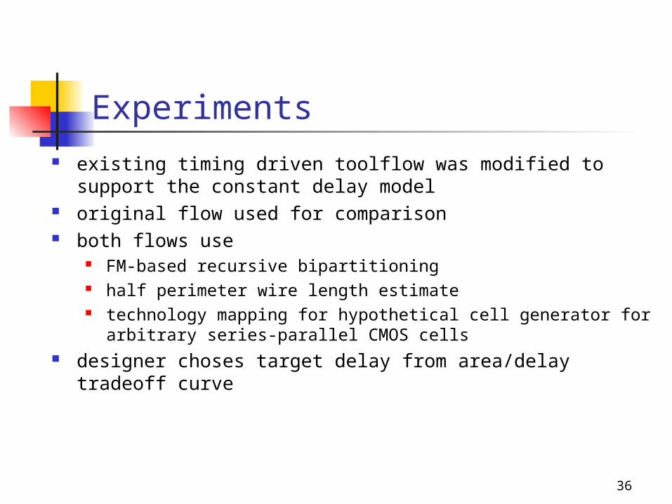
Experiments existing timing driven toolflow was modified to support the
constant delay model original flow used for comparison both flows use
FM-based recursive bipartitioning half perimeter wire length estimate technology mapping for hypothetical cell generator for arbitrary
series-parallel CMOS cells designer choses target delay from area/delay tradeoff curve

37
Technology Mapping & Gate Sizing
gate delay: f(C) gate area: fixed circuit delay: unknown circuit area: known approx.
Placement (Recursive Partitioning)
heuristic edge weighting
cut cost estimates circuit delay
static timing analysis
timing not met
Conventional Timing Driven Flow
Technology Mapping & Gate Sizing
gate delay: fixed gate area: f(C) circuit delay: fixed circuit area: unknown
Placement (Recursive Partitioning)
wire length updates
cut cost accurately reflects circuit area
computation of partition sizes
computation of area sensitivities
Proposed Constant Delay Based Flow
Preprocessing

38
Experimental Results
C342
C499
C880
C1355
C2670
C3540
C5315
C6288
C7552
Conventional Proposed Circuit Target Delay Area Delay Area Delay
C432 1.80 6.34 1.81 5.87 1.81 C499 1.64 17.5 1.66 15.0 1.68 C880 1.50 12.8 1.50 10.3 1.48 C1355 2.10 20.9 2.08 19.5 2.09 C2670 1.20 26.7 1.21 22.1 1.26 C3540 2.73 49.2 2.74 36.2 2.74 C5315 3.00 70.2 3.03 56.4 3.03 C6288 1.18 83.0 1.18 82.8 1.17 C7552 2.60 89.0 2.56 75.9 2.59 375,6 324,1 118% 100%

39
Conclusion
we exploit properties of the constant delay model to simplify and improve the placement process
the exact area costs of a cell move can be calculated based on area sensitivities
15% area improvement compared to conventional approach
computationally efficient