improvements to the bond wrench test · 11th lnternational bricklblock masonry conference tongji...
TRANSCRIPT
11th lNTERNATIONAL BRICKlBLOCK MASONRY CONFERENCE
TONGJI UNIVERSITY, SHANGHAI, CHINA, 14 - 16 OCTOBER 1997
IMPROVEMENTS TO THE BOND WRENCH TEST
Wimalasena Samarasinghe·, Steve Lawrence t & Adrian Paget
1. ABSTRACT
Although the bond wrench is a simple and practical apparatus to measure the bond strength between masonry units and mortar, doubts have arisen in recent years about the repeatability and reproducibility of the test method. Investigations of the bond wrench test for the purpose of addressing these concems are discussed here.
lnitially, a comparative test series was performed using bond wrench and bond beam test methods on brick-mortar couplets. It was confirmed that the bond wrench in its present form is not reliable as a means to predict bond since the average bond strengths resulting from bond wrench tests are significantly lower than those from beam tests. Both test methods yielded the same degree of variability. Consequently, the effect on the stress distribution of geometrical configuration of the wrench and the c1amping effect of the restraining frame were investigated by experimental and analytical means to understand the conditions imposed by thewrench on the test specimen. It is shown that the stress distribution through the thickness of the specimen is non-linear and the stresses along the tensile face of the test specimen are non-uniform.
2. INTRODUCTION
A bond test method must produce reliable information about bond, and the coefficient of variation of the test results must be within the normal range that is found with tests on masonry. The Australian Masonry Code, AS 3700-19881
, describes two methods for measuring bond strength - the bond wrench test and the beam test. Although the older beam test is still permissible, the preferred method of test is the bond wrench, because of its simplicity and the ability to test every joint in a masonry pier.
Keywords: Masonry; Bond Strength; Bond Wrench; Flexural Strength; Testing
• Senior Research Scientist, Division of Building, Construction & Engineering, CSIRO, Sydney t.Senior Principal Research Scientist, Division of Building, Construction & Engineering, CSIRO, Sydney I Dean, Faculty ofEngineering, Newcastle University, Newcastle, Australia
347

Although the bond wrench method of testing is becoming popular, there is no universally accepted configuration for the apparatus. The Australian Masonry Code describes the bond wrench in a conceptual manner without giving specific details as to how the test specimen should be clamped and loaded. The bond wrench described in ASTM ClO72-862 is specified in more detail than in AS 3700. However, the current Australian bond wrench is quite different from the ASTM wrench.
Despite the popularity of the technique, some concem has been expressed that the bond wrench yields a relatively high variability, and therefore a low characteristic bond strength, in contrast to the beam test. Therefore, a comprehensive investigation was performed to test the suitability of the bond wrench method of testing masonry. This constitutes part of a major joint research effort between the CSIRO Division of Building, Construction and Engineering and the University of Newcastle on the bond strength of masonry at micro and macro levels3
.
3. COMPARATIVE TESTS USING BOND BEAM AND BOND WRENCH
3.1 Test Specimens
In the usual beam test a stack-bonded pier (at least 7 courses high) is supported as a simple beam and loaded with two line loads near the third points. It gives one flexural tensile strength result from each pier, usually the weakest of several joints. Therefore the average of a group of beam flexural strengths is lower than the true mean joint strength whereas in the normal bond wrench test each joint in the stack-bonded pier is tested allowing true mean joint strength to be ca1culated. In order to compare the results derived from different test methods true joint strengths have to be compared. In other words, for a true comparative study each joint in the pier should be tested by both methods.
In a comparative study oftest methods, it is important that the test specimens should be similar as much as possible. In constructing a masonry pier, the vertical orientation produces a superimposed compression stress on the lower joints, which differs from bed joint to bed joint. Although the effect of pre-loading the joints on the flexural strength is not known, it was considered desirable to eliminate that effect.
In order to satisfy the above mentioned conditions, brick-rIÍortar couplets were prepared for both bond wrench and bond beam tests. To facilitate the beam tests, three units were glued with epoxy resin to both top and bottom of the couplets to make eight-high piers.
Three test series were performed. The couplets were fabricated in a specially designed jig in an attempt to minimise the variability due to workmanship. However, in the third test series an additional set of couplets was built by a professional bricklayer (bricklayer's specimens) in parallel with the specimens prepared in the controlled way (controlled specimens) to assess the variability caused by workmanship.
Ali the specimens were prepared with 1:1:6 (cement: lime: sand) mortar. For each test series four batches of mortar were mixed to prepare the specimens. The first test series used solid paver bricks (230 rnrn x 115 rnrn x 70 rnrn) and the second and third test series used 10-hole extruded bricks (229 rnrn x 109 rnrn x 75 rnrn).
348
3.2 Test Methods
Materiais of a brittle nature may perform differently when subjected to different rates of loading. While no attempt was made to measure the effect of loading rate on the measured strengths, it was considered desirable that a steady uniform rate of load increase should be used in ali the tests. The load was applied usmg a servo-controlled loading system. Couplets were tested by the bond wrench and beam methods seven days after construction.
The bond wrench used was developed at Deakin University and is widely used in Australia. It has a lever about I m long and weighs about 3.4 kg. At one end of the lever arejaws (gripping bars) which can be adjusted to fit the thickness ofthe masonry. The gripping bar on the compression face (19 mm x 19 mm x 200 mm) grips the brick about 40 mm below the top face. The gripping bar on the tension face is 15 mm wide x 19 mm high x 200 mm longo While testing, the bottom brick was c1amped to a restraining frame about 2-3 mm below the bottom interface according to the specifications given in AS 3700.
The beam test used a support span of 600 mm and a span between load points of 320 mm. Water-filled hoses were used to even out irregularities under the load and support bars. Self-aligning, stiff support bars were used to elirninate any twisting effect due to the inevitable lack of precise straightness in the specimens.
3.3 Test Results
A surnrnary of test results is shown in Table 1. In ali the tests failure occurred either at the brick-mortar interface or partially at the interface and in the mortar. In the second test series sixteen beam specimens were damaged while handling and only 14 specimens were tested.
1 sI Series 2nd Series 3,d Series
Bricklayer's Controlled Specimens Specimens
Beam Wrench Beam Wrench Beam Wrench Beam Wrench
NO. of 30 30 14 29 27 31 29 27 Tests
Mean 1.38 1.01 0.8 0.65 1.33 0.95 1.13 0.83 (MPa)
S.D. 0.41 0.34 0.12 0.13 0.35 0.21 0.22 0.09 (MPa)
C.V. 0.30 0.33 0.15 0.20 0.26 0.22 0.20 0.11
Table 1 . Bond Strength Results
3.4 Analysis and Comments
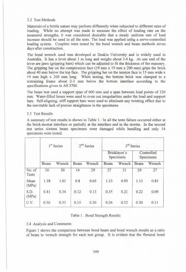
Figure 1 shows the comparison between bond beam and bond wrench results as a ratio of beam to wrench strength for each test group. It is evident that the flexural bond
349
strength of c1ay brick couplets from the bond wrench method are consistently lower than the values from the bond beam method.
1.6 1.37 1.40 1.36 1.23 o
.~ '"' 1.2 .r: o: <.J I:: .r: Q)
~ ~ 0.8 Q) .....
~ E r/J tO "CI Q)
I:: e 0.4 o c:l
0.0
2 3 (Bricklayer's 3 (Controlled Specimens) Specimens)
Test Series
Figure 1 . Ratio ofBeam to Wrench Strength
A three-way analysis of variance was performed on the beam and wrench test results to check the significance and interaction ofthe factors: Test Series (4 leveis), Mortar Batch (4 leveis) and Test Method (wrench and beam). The analysis confirmed t..hat the interactions between the factors are not significant, that the batch effect can be treated as random and that the test series and the test method factors are significant. In other words, there are significant differences shown in the results between the four series of tests and between the beam and wrench test methods.
Figure 2 shows a comparison of variability resulting from the various test series and test methods. Statistical analysis reveals that there is no significant difference in variability between the wrench and beam tests. The first and second test series show a lower variability in the beam tests than in the wrench tests whereas in the third test series both types of specimen show a higher variability in the beam tests than in the wrench tests. The lower variability shown by the specimens built in the controlled way compared with the specimens built by the professional bricklayer (in the third test series) illustrates that the controlled method reduces the variability due to workmanship effects.
350

I': 0.4 o .~
.~ 0.3 > .... o 0.2 'i'i !Il 'ü 0.1 !5 !Il o O U
2 3 (BrickJayer's 3 (ControJled Specimens) Specimens)
Test Series
DCV Beam
IICV Wrench
Figure 2. Coefficients ofVariation from Beam and Wrench Tests
Recently, Van der Pluijm4 has done an experimental investigation to identify a simple test method for European standards with special reference to the bond wrench test. He carried out a comparative study using five different test methods with two types of masonry (brick and calcium silicate). The five test methods are bond wrench test and 4-point bending test on 6-course stack-bonded piers, direct-tensile test on couplets with restrained end platens and hinged end platens and 4-point bending test on wallettes. In the 4-point bending test on stack-bonded piers ollly one joint was subjected to apure bending state, whereas in the wallette test 4 joints were under pure flexure. The bond wrench used is significantly different from the Australian bond wrench that was used in this investigation.
According to Van der Pluijm the bond wrench and bond beam tests on 6 course stackbonded piers produced approximately the same mean bond strengths. Therefore he confirmed that the bond wrench test method could be used as a means to predict bond. However, the true joint flexural strength derived from wallettes (2.5 brick wide) shows that the wrench strength measured is only 84% of the true joint strength. This difference may be due to the presence ofheadjoints in the wallettes.
Therefore, while the investigation reported here shows a significant difference between wrench and beam results, the tests of Van der Pluijm do not. The major difference between the two investigations is the geometrical configurations of the wrenches used. This indicates that the bond wrench configuration can have a significant influence on its performance.
4. CONDITIONS IMPOSED BY BOND WRENCH
It is believed that the difference between the bond wrench and bond beam results described earlier can be fully explained by considering the stress distributions in the bond wrench specimen due to specimen clamping and the design of the wrench itself. A comprehensive experimental and analytical investigation was performed to study the stress distribution at the interface between brick and mortar when the specimen is tested by the bond wrench.
351

4.1 Experimental Study using a Calibration Block
lnitially, a device for measuring the strains that a bond wrench applies to a typical masonry specimen was developed and calibrated. The device consists of a strain-gauged aluminium block with dimensions similar to a typical brick-mortar couplet. Figure 3 shows a schematic diagram of this block and its strain gauge configuration. Nineteen gauges were mounted where the interface-between brick and mortar is normally located. (Note that strain gauge numbers 10 to 19 were not used). The strain gauges were only fixed on one of the longer faces, since the presence of the gripping bar of the bond wrench obstructs the other face .
Gauges 20 to 26 Gauges 1 to 7
Tension Face
28 29 9
,-.......................................................................................................... .............................................................. --~
"""----I ..... · ·········· · ······ .... __ -----I~ /. 230 mm ~ "I::>
Figure 3. Calibration Block Showing the Strain Gauge Locations
The strain-gauged aluminium block was tested under uniform compression-to check the functionality of the gauges and to calculate the elastic modulus of aluminium.
The measured strains were reasonably uniform and all the gauges functioned properly. The elastic modulus of the aluminium was measured as 68,700 MPa, which agrees well with published values.
The strain-gauged aluminium calibration block was then loaded by the bond wrench. Firstly, the aluminium block was carefully aligned with the centreline of the retaining frame and c1amped with the centreline of all the gauges approximately 10 mm above the top edge of the c1amp. The c1amping pressure was applied manually (to the leveI normally used in a test). Three sets of strain readings were taken - prior to clamping, after c1amping and after application of loads.
The average strains measured on the sides of the calibration block (the average of corresponding gauges between numbers 1-7 and 20-26) are shown in Figure 4. Lines are drawn to show the strain distribution through the thickness at various stages. The initial condition (with the calibration block sitting on a leveI surface) coincides with the horizontal axis of the graph. The other two curves represent the conditions imposed by the bottom c1amps and by the bond wrench with 495 N load applied at the end of the lever. The expected distribution according to the conventional bending formula is shown for comparison.
352

'" o
20
10
_-N' -10
-20
tension
20 40
compression
Distance (mm)
--+--Zero
- .. - Clamped
··.·-495N
- - - Bending Fonnula
60
Figure 4. Vertical Strains Through the Thickness ofthe Calibration Block
The results reveal that the strain distribution through the thickness of the specimen is markedly different from that shown by the conventional bending fonnuia. It appears that the c1amping by the retaining frame induces a significant tensile strain at the extreme fibres of the test specimen. An investigation of the ASTM bond wrench by McGinley5 has shown similar results.
As a criterion for acceptance of materiais and workmanship in masonry construction, AS 3700 has adopted a minimum flexural strength of 0.2 MPa. The maximum strain value recorded due to c1amping pressure on the calibration block is equivalent to a stress of 0.17 MPa. This unaccounted stress produced in actual testing could lead to the rejection of acceptable masonry. The specified distance between the bottom interface and the c1amps in AS 3700 (1 to 3 mm) may be quite criticai to this effect. Increasing this distance would reduce the stress concentration effects.
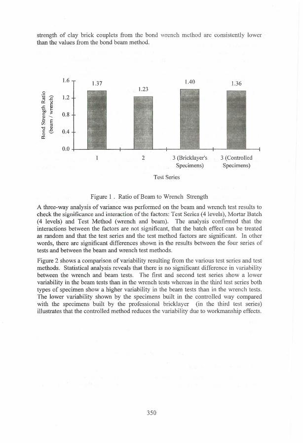
Figure 5 shows the distribution of strain measured across the tensile face of the calibration block and c1early shows that the bond wrench produces a non-unifonn stress distribution on the tension face of the test specimen. It produces a significantly high, localised stress at the centre ofthe test specimen, right below where the tensile gripping bar connects to the loading lever. Masonry is a brittle material, and therefore failure is likely to be triggered by the peak stress and the test will tend to underestimate the bond strength. According to Figure 5 the predicted bond strength could be as much as 43% less than the actual bond strength. The results also illustrate the effect of c1amping strains on the tension face of the specimen.
353
•
30 -+--zero
'" o 20
- {] - clamped ~ -+--495N I::: 'a 10 !:l - - - Bending Formula r/1
O ___ -o- - - - o- - - -IJ
O 100 200 300
Distance From Side Face (mm)
Figure 5. Vertical Strains on the Tensile Face ofthe Calibration Block
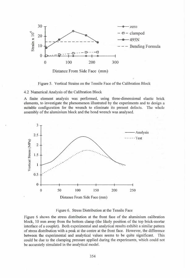
4.2 Nurnerical Analysis ofthe Calibration Block
A finite element analysis was perforrned, using three-dimensional e1astic brick elements, to investigate the phenomenon illustrated by the experiments and to design a suitable configuration for the wrench to eliminate its present defects. The whole assembly of the alurniniurn block and the bond wrench was analysed.
3
2.5 ';?
~ 2 '--"
'" '" g l.5 r:rJ
'i<i u 'i: v >
0.5
O
O 50 100 150
Distance From Side Face (mm)
200
--Analysis _ ... - -Test
250
Figure 6. Stress Distribution at the Tensile Face
Figure 6 shows the stress distribution at the front face of the alurniniurn calibration block, 10 mm away from the bortom c1amp (the likely position of the top brick-mortar interface of a couplet). Both experimental and analytical results exhibit a similar partem of stress distribution with a peak at the centre at the front face. However, the difference between the experimental and analytical values seems to be quite significant. This could be due to the c1amping pressure applied during the experiments, which could not be accurately simulated in the analytical mode!.
354
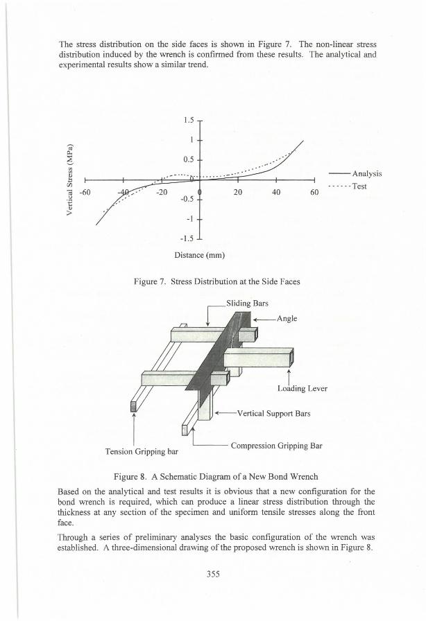
The stress distribution on the side faces is shown in Figure 7. The non-linear stress distribution induced by the wrench is confirmed from these results. The analytical and experimental results show a similar trend.
1.5
r-. tU
Cl..
6 0.5 CIl
--Analysis CIl Q)
b CIl - - - - - -Test ~ -60 20 40 60 ()
.€ Q)
> -1
-1.5
Distance (mm)
Figure 7. Stress Distribution at the Side Faces
-Vertical Support Bars
Tension Gripping bar '----- Compression Gripping Bar
Figure 8. A Schematic Diagram of a New Bond Wrench
Based on the analytical and test results it is obvious that a new configuration for the bond wrench is required, which can produce a linear stress distribution through the thickness at any section of the specimen and uniform tensile stresses along the front face.
Through a series of preliminary analyses the basic configuration of the wrench was established. A three-dimensional drawing ofthe proposed wrench is shown in Figure 8.
355

Supporting the gripping bars at two points minimises the stress peak at the centre of the tension face of the test specimen, unlike in the present wrench. A sensitivity analysis revealed that supporting them at the fifth points gives the most satisfactory results. The detailed results are to be published elsewhere.
5. CONCLUSIbN
Tests have shown that a commonly used bond wrench can give results significantly different fiom the true flexural strength of masonry. Detailed investigation has shown that the present bond wrench apparatus produces a non-uniform stress distribution in the test specimen, which differs significantly from the assumed linear distribution. Most importantly, due to its geometrical shape, a localised stress peak occurs near the tensile face of the test specimen causing a premature bond failure. This can lead to underestimates ofthe bond strength ofmasonry by as much as 43%.
This study confirms that standardising the bond wrench configuration is essential to achieving repeatable and reproducible test results.
6. ACKNOWLEDGMENT
The work described has benefited from financiaI support given by the Clay Brick and Paver Institute of Australia, the Concrete Masonry Association of Australia, the Cement and Concrete Association of Australia and the Australian Research Council.
7. REFERENCES
1. SAA Masonry Code, AS 3700-1988, Standards Association of Australia, Sydney, 1988.
2. American Society for Testing and MateriaIs, ASTM CI072-94, "Standard Test Method for Measurement ofMasonry Flexural Bond Strength", 1994.
3. Lawrence, S.J. & Page, A.W., "Bond Studies in Masonry", Proceedings of the 10th
International Brick and Block Masonry Conference, Calgary, Alberta, Canada, July 1994, pp. 909 - 917.
4. Van der Pluijm, R., " Measuring of Bond - Comparative Experimental Research", Proceedings of the Seventh North American Masonry Conference, South Bend, Indiana, June 1996, pp. 267-281 .
5. McGinley, W M, 1993, "Bond Wrench Testing - Calibration Procedures and Proposed Apparatus and Testing Procedure Modifications", Proceedings of the Sixth North American Masonry Conference, Philadelphia, Pennsylvania, June 1993, pp.159-172. I
356