improve equipment efficiency in operating plants
TRANSCRIPT
Improve Equipment Efficiency in
Operating Plants
Presented by
Mr. Wayne Flintoff, Chevron, AustraliaMr. Wayne Flintoff, Chevron, Australia
&
Mr. Manjul N Saxena,
Global Machinery Consultants Pty. Ltd., Australia
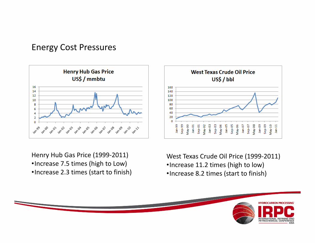
Energy Cost Pressures
Henry Hub Gas Price (1999-2011)
•Increase 7.5 times (high to Low)
•Increase 2.3 times (start to finish)
West Texas Crude Oil Price (1999-2011)
•Increase 11.2 times (high to low)
•Increase 8.2 times (start to finish)
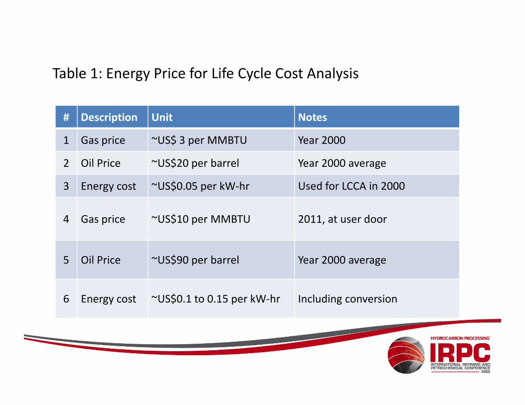
Table 1: Energy Price for Life Cycle Cost Analysis
# Description Unit Notes
1 Gas price ~US$ 3 per MMBTU Year 2000
2 Oil Price ~US$20 per barrel Year 2000 average
3 Energy cost ~US$0.05 per kW-hr Used for LCCA in 2000
4 Gas price ~US$10 per MMBTU 2011, at user door
5 Oil Price ~US$90 per barrel Year 2000 average
6 Energy cost ~US$0.1 to 0.15 per kW-hr Including conversion
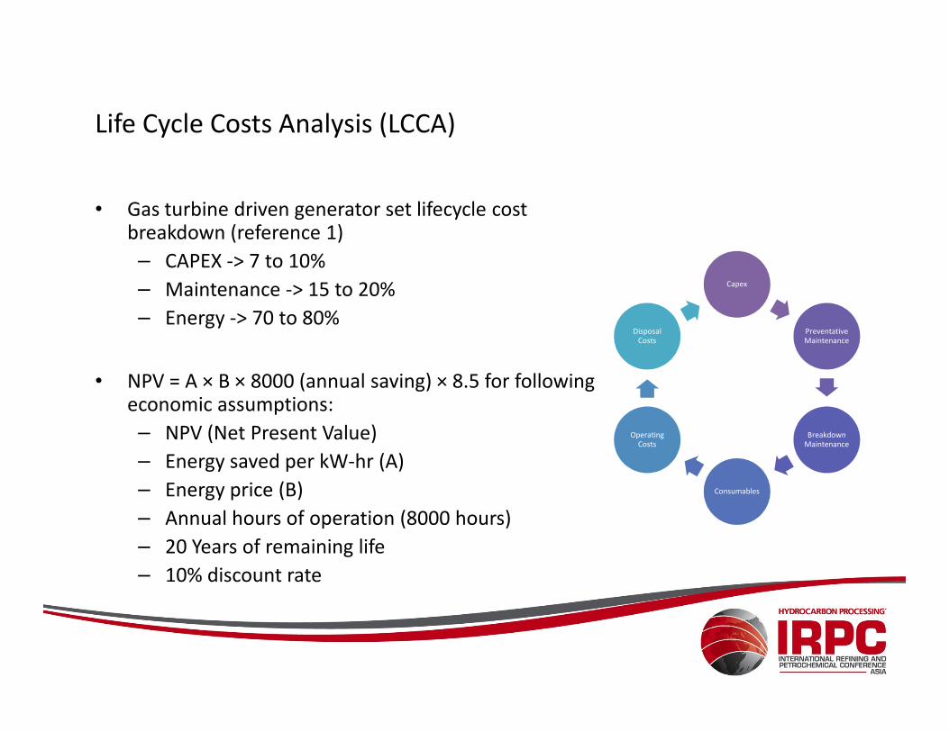
• Gas turbine driven generator set lifecycle cost breakdown (reference 1)
– CAPEX -> 7 to 10%
– Maintenance -> 15 to 20%
– Energy -> 70 to 80%
Capex
Preventative Maintenance
Disposal Costs
Life Cycle Costs Analysis (LCCA)
• NPV = A × B × 8000 (annual saving) × 8.5 for following economic assumptions:
– NPV (Net Present Value)
– Energy saved per kW-hr (A)
– Energy price (B)
– Annual hours of operation (8000 hours)
– 20 Years of remaining life
– 10% discount rate
Breakdown Maintenance
Consumables
Operating Costs
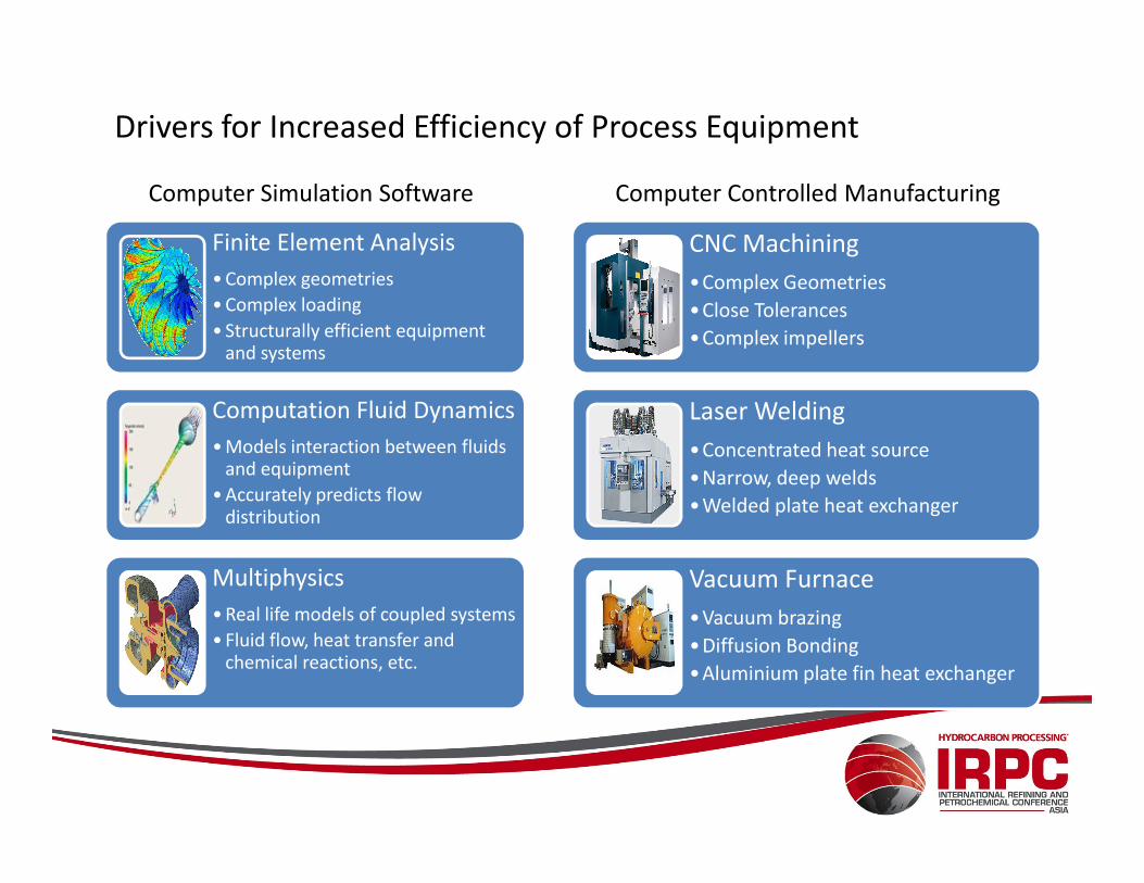
Drivers for Increased Efficiency of Process Equipment
CNC Machining
•Complex Geometries
•Close Tolerances
•Complex impellers
Laser Welding
•Concentrated heat source
Finite Element Analysis
• Complex geometries
• Complex loading
• Structurally efficient equipment and systems
Computation Fluid Dynamics
• Models interaction between fluids
Computer Simulation Software Computer Controlled Manufacturing
•Concentrated heat source
•Narrow, deep welds
•Welded plate heat exchanger
Vacuum Furnace
•Vacuum brazing
•Diffusion Bonding
•Aluminium plate fin heat exchanger
• Models interaction between fluids and equipment
• Accurately predicts flow distribution
Multiphysics
• Real life models of coupled systems
• Fluid flow, heat transfer and chemical reactions, etc.
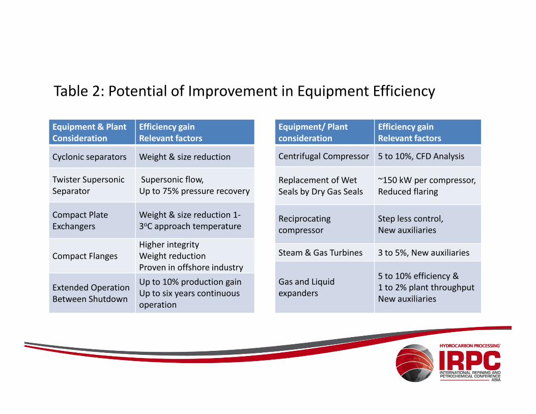
Table 2: Potential of Improvement in Equipment Efficiency
Equipment & Plant
Consideration
Efficiency gain
Relevant factors
Cyclonic separators Weight & size reduction
Twister Supersonic
Separator
Supersonic flow,
Up to 75% pressure recovery
Equipment/ Plant
consideration
Efficiency gain
Relevant factors
Centrifugal Compressor 5 to 10%, CFD Analysis
Replacement of Wet
Seals by Dry Gas Seals
~150 kW per compressor,
Reduced flaring
Compact Plate
Exchangers
Weight & size reduction 1-
3oC approach temperature
Compact Flanges
Higher integrity
Weight reduction
Proven in offshore industry
Extended Operation
Between Shutdown
Up to 10% production gain
Up to six years continuous
operation
Reciprocating
compressor
Step less control,
New auxiliaries
Steam & Gas Turbines 3 to 5%, New auxiliaries
Gas and Liquid
expanders
5 to 10% efficiency &
1 to 2% plant throughput
New auxiliaries
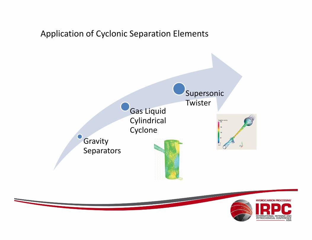
Application of Cyclonic Separation Elements
Gas Liquid Cylindrical
Supersonic Twister
Gravity Separators
Cylindrical Cyclone
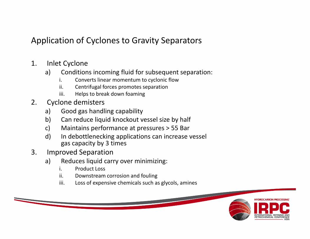
Application of Cyclones to Gravity Separators
1. Inlet Cyclone a) Conditions incoming fluid for subsequent separation:
i. Converts linear momentum to cyclonic flow
ii. Centrifugal forces promotes separation
iii. Helps to break down foaming
2. Cyclone demistersa) Good gas handling capability
b) Can reduce liquid knockout vessel size by halfb) Can reduce liquid knockout vessel size by half
c) Maintains performance at pressures > 55 Bar
d) In debottlenecking applications can increase vessel gas capacity by 3 times
3. Improved Separationa) Reduces liquid carry over minimizing:
i. Product Loss
ii. Downstream corrosion and fouling
iii. Loss of expensive chemicals such as glycols, amines
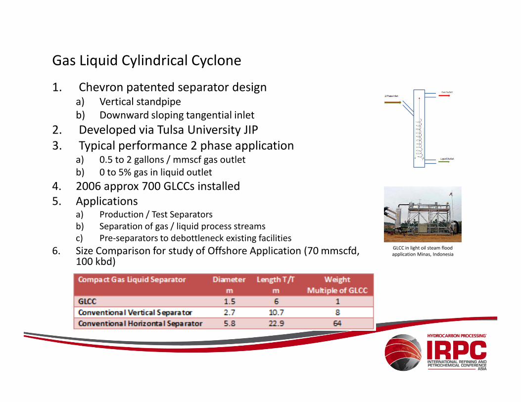
Gas Liquid Cylindrical Cyclone
1. Chevron patented separator designa) Vertical standpipe
b) Downward sloping tangential inlet
2. Developed via Tulsa University JIP
3. Typical performance 2 phase applicationa) 0.5 to 2 gallons / mmscf gas outlet
b) 0 to 5% gas in liquid outlet
4. 2006 approx 700 GLCCs installed
5. Applications5. Applicationsa) Production / Test Separators
b) Separation of gas / liquid process streams
c) Pre-separators to debottleneck existing facilities
6. Size Comparison for study of Offshore Application (70 mmscfd, 100 kbd)
GLCC in light oil steam flood
application Minas, Indonesia
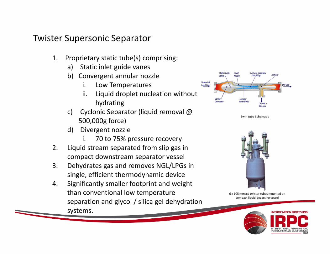
Twister Supersonic Separator
1. Proprietary static tube(s) comprising:
a) Static inlet guide vanes
b) Convergent annular nozzle
i. Low Temperatures
ii. Liquid droplet nucleation without
hydrating
c) Cyclonic Separator (liquid removal @
500,000g force)
d) Divergent nozzle
Swirl tube Schematic
d) Divergent nozzle
i. 70 to 75% pressure recovery
2. Liquid stream separated from slip gas in
compact downstream separator vessel
3. Dehydrates gas and removes NGL/LPGs in
single, efficient thermodynamic device
4. Significantly smaller footprint and weight
than conventional low temperature
separation and glycol / silica gel dehydration
systems.
6 x 10⁵ mmscd twister tubes mounted on
compact liquid degassing vessel
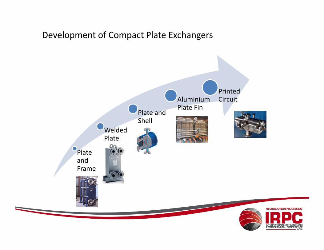
Development of Compact Plate Exchangers
Plate and Shell
Aluminium Plate Fin
Printed Circuit
Plate and Frame
Welded Plate
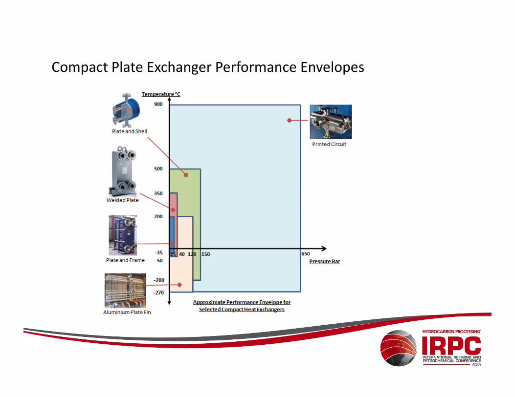
Compact Plate Exchanger Performance Envelopes

Advantages of Compact Heat Exchangers
• Corrugated Plate Design results in Turbulent Flow, and
– Low Fouling
– High heat transfer ( 3 to 5 times that of S&T HEX)
• 5 to 10 times greater heat transfer surface area per unit volume than S&T HEX
• 1/5th size of conventional S&T HEX
• Significant weight reduction; BAPHE can be 95% lighter than S&T
• Custom designed for thermal / hydraulic requirements of service• Custom designed for thermal / hydraulic requirements of service
• Approach temperatures of 1 to 3oC c/w 5 to 10oC for S&T HEX
• Low inventory reduces plant risk exposure
• Plate and shell ideal for debottlenecking as easily fits in shell of existing S&T and Kettle Reboiler.
• High integrity of PCHEs improves process system integrity
• Lower CAPEX particularly when using exotic alloys.
• Lower OPEX due to improved heat recovery and reduction in plant heating and cooling loads.
• Narrow flow passages limits use to clean service or applications with pre-filtration.
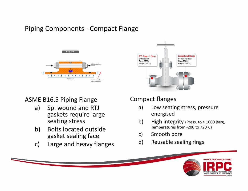
Piping Components - Compact Flange
ASME B16.5 Piping Flange Compact flangesASME B16.5 Piping Flange
a) Sp. wound and RTJ gaskets require large seating stress
b) Bolts located outside gasket sealing face
c) Large and heavy flanges
Compact flanges
a) Low seating stress, pressure energised
b) High integrity (Press. to > 1000 Barg,
Temperatures from -200 to 720oC)
c) Smooth bore
d) Reusable sealing rings
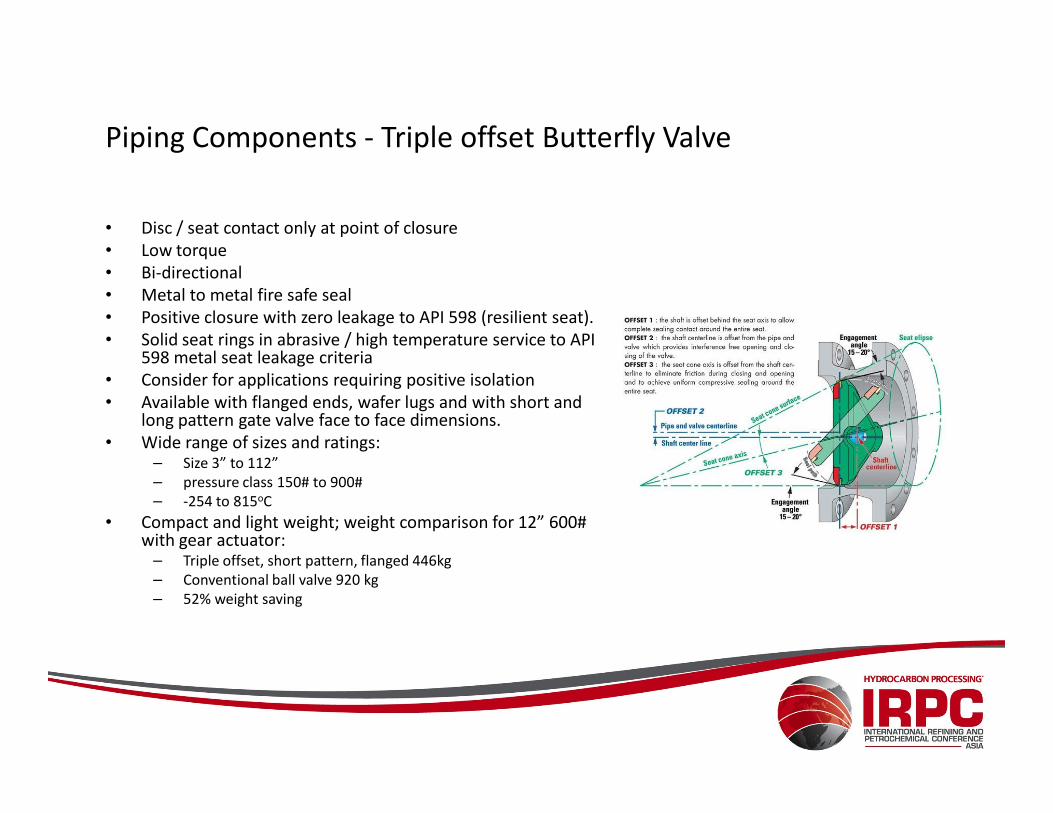
Piping Components - Triple offset Butterfly Valve
• Disc / seat contact only at point of closure
• Low torque
• Bi-directional
• Metal to metal fire safe seal
• Positive closure with zero leakage to API 598 (resilient seat).
• Solid seat rings in abrasive / high temperature service to API 598 metal seat leakage criteria
• Consider for applications requiring positive isolation
• Available with flanged ends, wafer lugs and with short and • Available with flanged ends, wafer lugs and with short and long pattern gate valve face to face dimensions.
• Wide range of sizes and ratings:– Size 3” to 112”
– pressure class 150# to 900#
– -254 to 815oC
• Compact and light weight; weight comparison for 12” 600# with gear actuator:
– Triple offset, short pattern, flanged 446kg
– Conventional ball valve 920 kg
– 52% weight saving
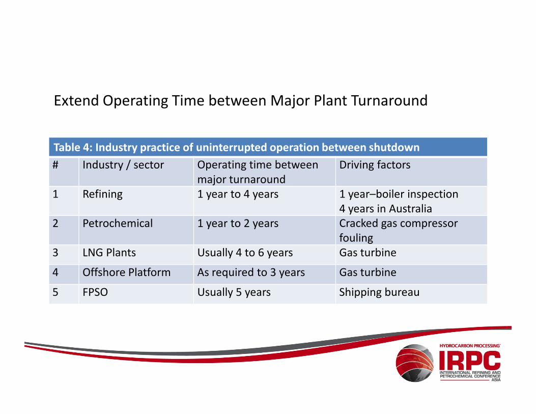
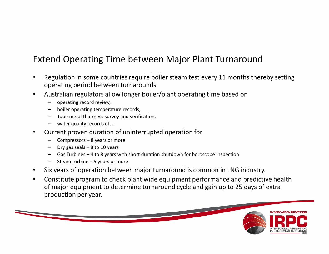
Extend Operating Time between Major Plant Turnaround
Table 4: Industry practice of uninterrupted operation between shutdown
# Industry / sector Operating time between
major turnaround
Driving factors
1 Refining 1 year to 4 years 1 year–boiler inspection
4 years in Australia 4 years in Australia
2 Petrochemical 1 year to 2 years Cracked gas compressor
fouling
3 LNG Plants Usually 4 to 6 years Gas turbine
4 Offshore Platform As required to 3 years Gas turbine
5 FPSO Usually 5 years Shipping bureau
Extend Operating Time between Major Plant Turnaround
• Regulation in some countries require boiler steam test every 11 months thereby setting operating period between turnarounds.
• Australian regulators allow longer boiler/plant operating time based on – operating record review,
– boiler operating temperature records,
– Tube metal thickness survey and verification,
– water quality records etc.
• Current proven duration of uninterrupted operation for– Compressors – 8 years or more
– Dry gas seals – 8 to 10 years
– Gas Turbines – 4 to 8 years with short duration shutdown for boroscope inspection
– Steam turbine – 5 years or more
• Six years of operation between major turnaround is common in LNG industry.
• Constitute program to check plant wide equipment performance and predictive health of major equipment to determine turnaround cycle and gain up to 25 days of extra production per year.
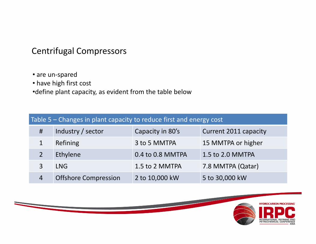
Centrifugal Compressors
Table 5 – Changes in plant capacity to reduce first and energy cost
• are un-spared
• have high first cost
•define plant capacity, as evident from the table below
Table 5 – Changes in plant capacity to reduce first and energy cost
# Industry / sector Capacity in 80’s Current 2011 capacity
1 Refining 3 to 5 MMTPA 15 MMTPA or higher
2 Ethylene 0.4 to 0.8 MMTPA 1.5 to 2.0 MMTPA
3 LNG 1.5 to 2 MMTPA 7.8 MMTPA (Qatar)
4 Offshore Compression 2 to 10,000 kW 5 to 30,000 kW
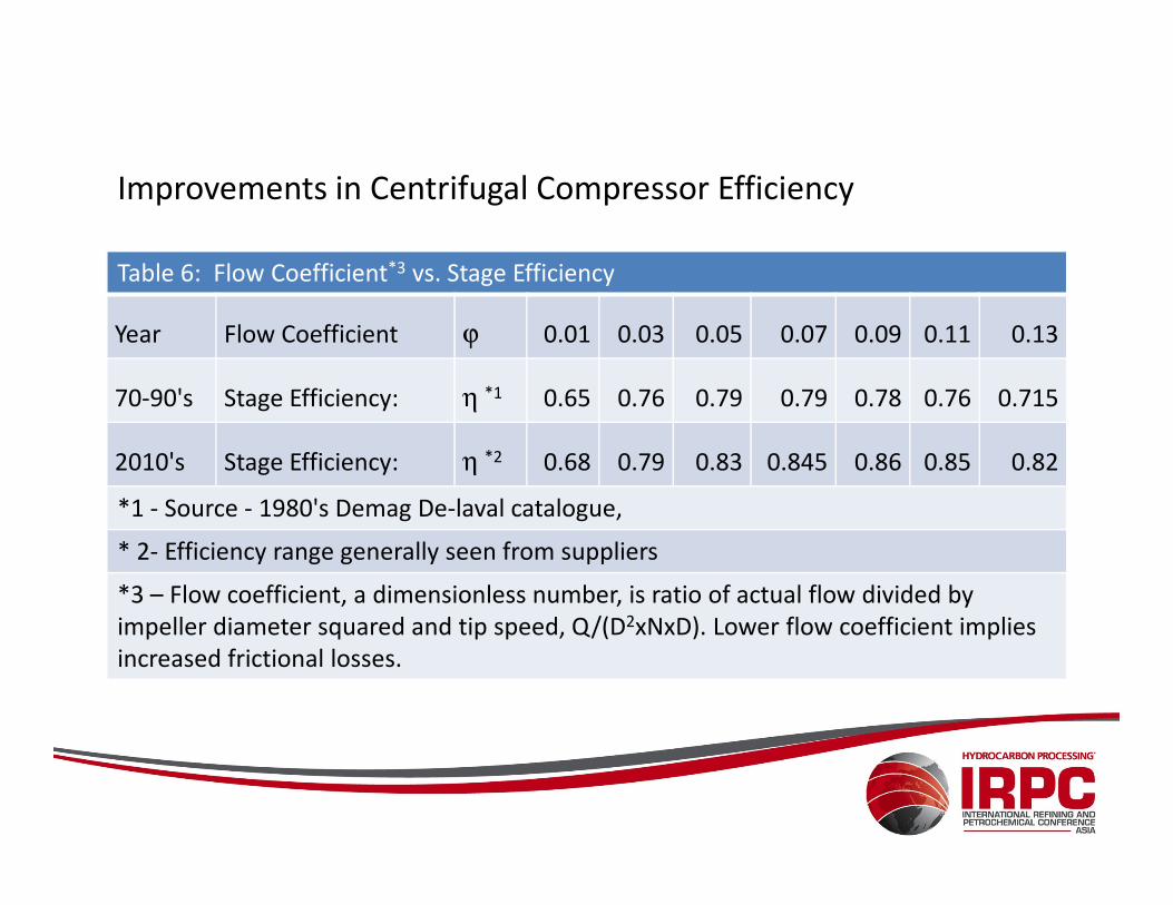
Improvements in Centrifugal Compressor Efficiency
Table 6: Flow Coefficient*3 vs. Stage Efficiency
Year Flow Coefficient ϕ 0.01 0.03 0.05 0.07 0.09 0.11 0.13
70-90's Stage Efficiency: η *1 0.65 0.76 0.79 0.79 0.78 0.76 0.715
2010's Stage Efficiency: η *2 0.68 0.79 0.83 0.845 0.86 0.85 0.822010's Stage Efficiency: η *2 0.68 0.79 0.83 0.845 0.86 0.85 0.82
*1 - Source - 1980's Demag De-laval catalogue,
* 2- Efficiency range generally seen from suppliers
*3 – Flow coefficient, a dimensionless number, is ratio of actual flow divided by
impeller diameter squared and tip speed, Q/(D2xNxD). Lower flow coefficient implies
increased frictional losses.
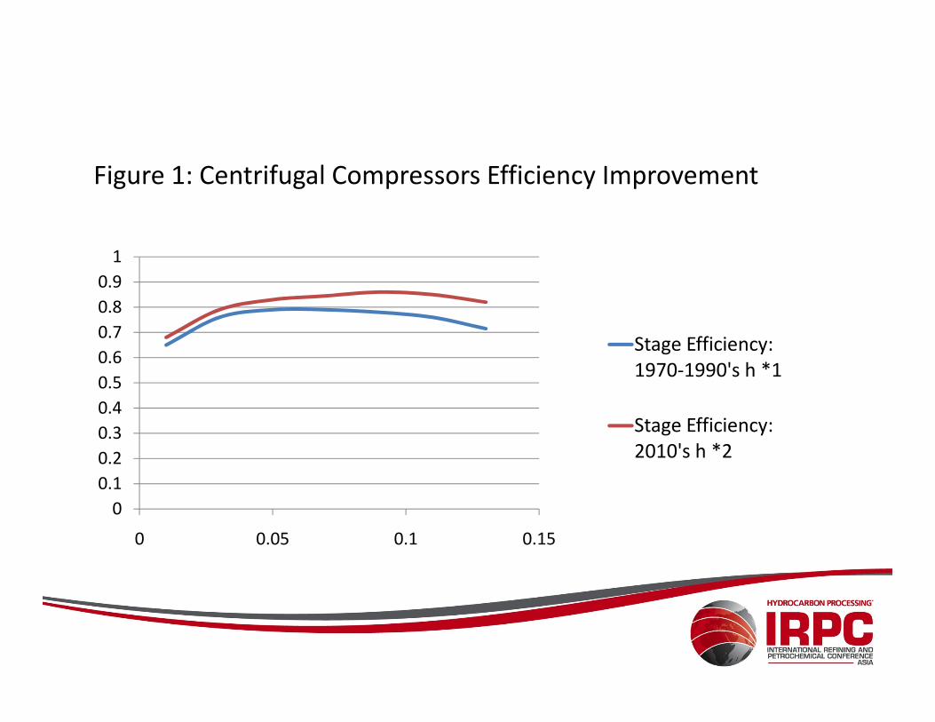
Figure 1: Centrifugal Compressors Efficiency Improvement
0.6
0.7
0.8
0.9
1
Stage Efficiency:
1970-1990's h *1
0
0.1
0.2
0.3
0.4
0.5
0.6
0 0.05 0.1 0.15
1970-1990's h *1
Stage Efficiency:
2010's h *2
Design Improvements in Centrifugal Compressors
Many improvements in Impeller and Stator design:
– 3-d design impellers with lower frictional losses.
– Blade cutback in low flow coefficient impellers to enhance efficiency up to 1%.
– Better flow channel design available between impeller cover disk and inter-
stage labyrinth to reduce turbulence loss.
– Use labyrinth materials like silicon aluminum or PEEK to reduce inter-stage – Use labyrinth materials like silicon aluminum or PEEK to reduce inter-stage
losses between 2 to 5%.
– In ethylene plants, cracked-gas compression, consider Electro-less Nickel (EN)
coating to reduce fouling from polymerization.
– Single piece impellers up to 1.4m diameter with lower frictional losses are
available.
– In some cases, “Flange to Flange” overall efficiency up to 87% available.
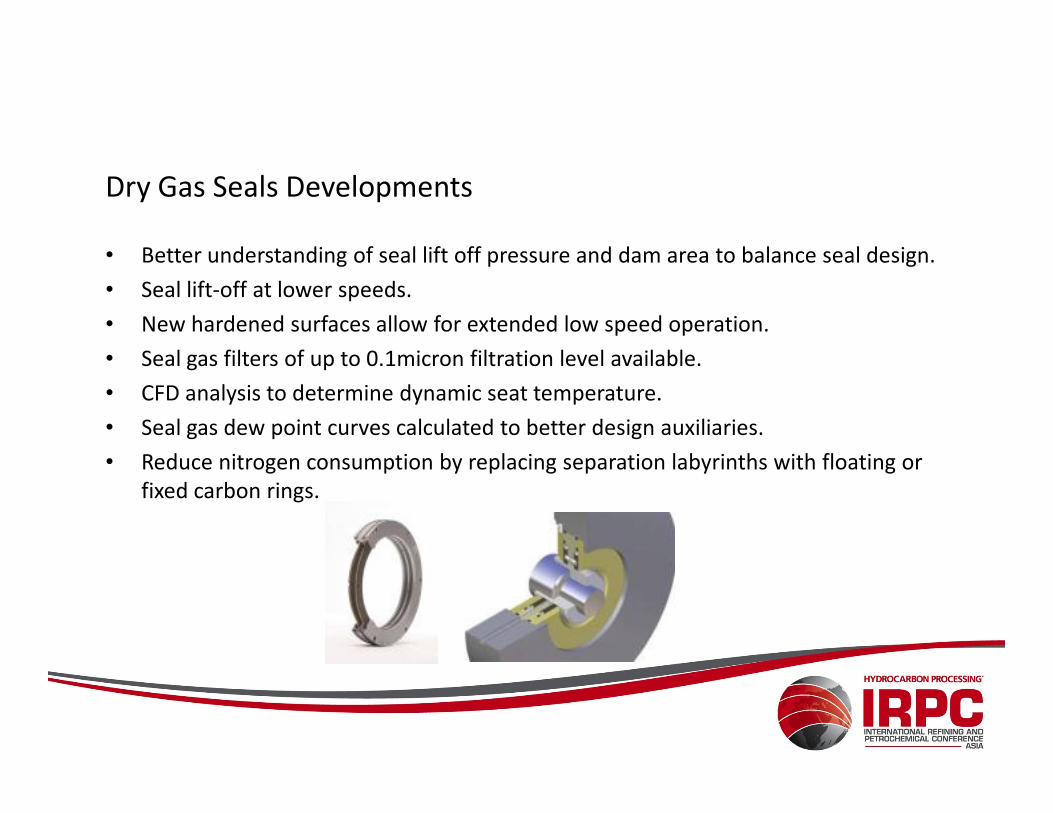
Dry Gas Seals Developments
• Better understanding of seal lift off pressure and dam area to balance seal design.
• Seal lift-off at lower speeds.
• New hardened surfaces allow for extended low speed operation.
• Seal gas filters of up to 0.1micron filtration level available.
• CFD analysis to determine dynamic seat temperature.
• Seal gas dew point curves calculated to better design auxiliaries.
• Reduce nitrogen consumption by replacing separation labyrinths with floating or
fixed carbon rings.
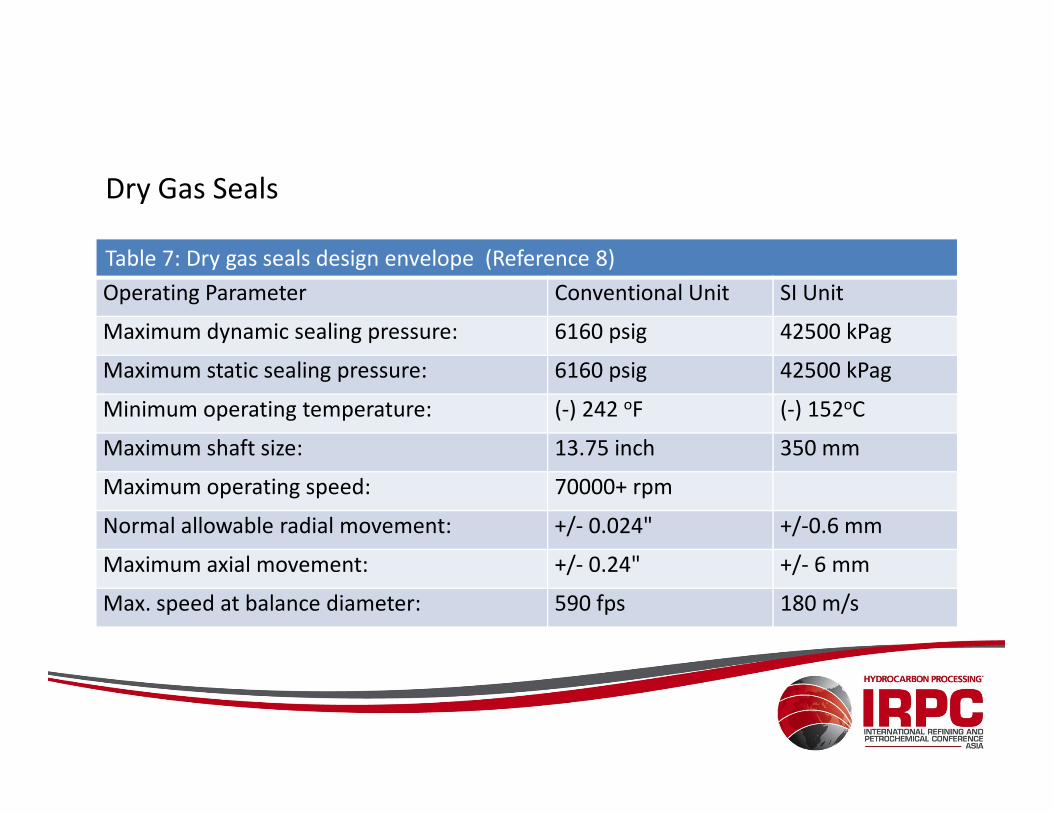
Dry Gas Seals
Table 7: Dry gas seals design envelope (Reference 8)
Operating Parameter Conventional Unit SI Unit
Maximum dynamic sealing pressure: 6160 psig 42500 kPag
Maximum static sealing pressure: 6160 psig 42500 kPag
Minimum operating temperature: (-) 242 oF (-) 152oCMinimum operating temperature: (-) 242 oF (-) 152oC
Maximum shaft size: 13.75 inch 350 mm
Maximum operating speed: 70000+ rpm
Normal allowable radial movement: +/- 0.024" +/-0.6 mm
Maximum axial movement: +/- 0.24" +/- 6 mm
Max. speed at balance diameter: 590 fps 180 m/s
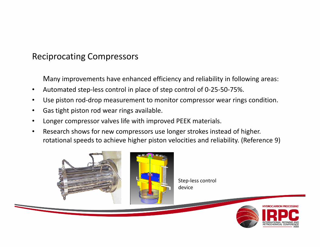
Reciprocating Compressors
Many improvements have enhanced efficiency and reliability in following areas:
• Automated step-less control in place of step control of 0-25-50-75%.
• Use piston rod-drop measurement to monitor compressor wear rings condition.
• Gas tight piston rod wear rings available.
• Longer compressor valves life with improved PEEK materials.• Longer compressor valves life with improved PEEK materials.
• Research shows for new compressors use longer strokes instead of higher.
rotational speeds to achieve higher piston velocities and reliability. (Reference 9)
Step-less control
device
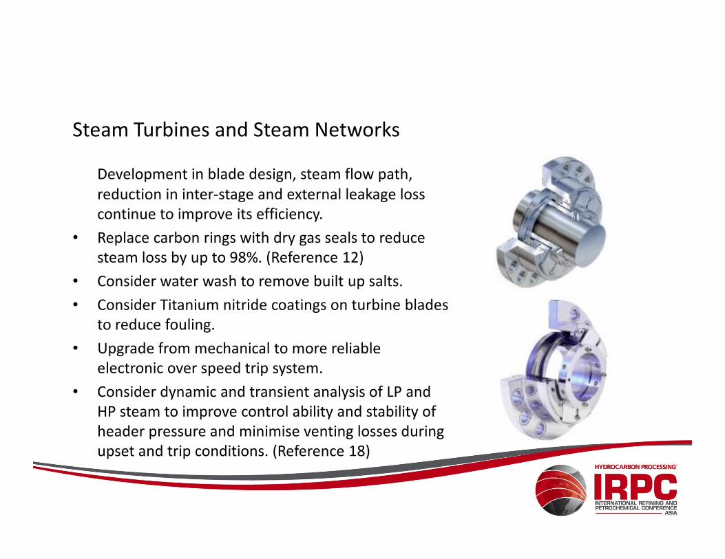
Steam Turbines and Steam Networks
Development in blade design, steam flow path,
reduction in inter-stage and external leakage loss
continue to improve its efficiency.
• Replace carbon rings with dry gas seals to reduce
steam loss by up to 98%. (Reference 12)
• Consider water wash to remove built up salts. • Consider water wash to remove built up salts.
• Consider Titanium nitride coatings on turbine blades
to reduce fouling.
• Upgrade from mechanical to more reliable
electronic over speed trip system.
• Consider dynamic and transient analysis of LP and
HP steam to improve control ability and stability of
header pressure and minimise venting losses during
upset and trip conditions. (Reference 18)
Gas Turbines
• Gas turbines ranging from 1 to 125 megawatts are used in Oil Industry.
• Poor quality traditional static inlet air filters can reduce air flow by 5%, output power by 10% and increase fuel gas consumption by 5%. Consider self cleaning filters to improve turbine efficiency by up to 10% and increase plant availability by 3 to 5 days per year.
• To improve efficiency and output • To improve efficiency and output
– Replace turbine compressor aft labyrinth with brush seals (~ 0.5% each).
– Replace with new seal materials and inter-stage brush seals in power turbine sections (2 to 3%).
• Better materials allow longer operation between inspection like
– Hot end turbine blades made from directionally solidified steel.
– Thermal barrier coating of hot end blades.
• Re-analyse fuel gas, consider coalescing filters to reduce fuel gas moisture to ensure longer turbine hot end life.
Gas and Liquid Expanders
• Consider pressure reduction of 2000 kPa (290 psi) or more across a JT (Joule
Thomsen) valve as candidates for energy recovery process in expanders.
• Power ranging from 100kW to 10,000 kW.
• Expanders can drive
– Compressors.
– Generators.– Generators.
• Potential for new applications in
– Pipeline gas pressure let down stations.
– LNG plants, unloading/storage terminals.
– Offshore Platforms and FPSO’s.
• Two-phase flow with recovery up to 10,000 barrels/day of LPG and Condensate.
• Pay back period’s range from few months to few years.
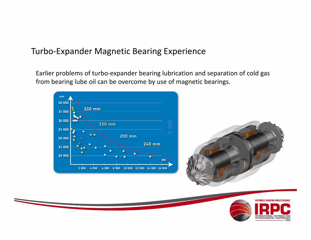
Turbo-Expander Magnetic Bearing Experience
Earlier problems of turbo-expander bearing lubrication and separation of cold gas
from bearing lube oil can be overcome by use of magnetic bearings.
• Mr. Wayne Flintoff wishes to convey his sincere thanks to Chevron, Australia.
• Mr. Manjul N Saxena wishes to convey his sincere thanks to INPEX for whom he
has been working for three years on Ichthys Onshore LNG project, Australia.
• We also wish to acknowledge with thanks for contributions from Siemens, General
Electric (GE), Elliott Ebara, MAN-Turbo, Dresser Rand, Rolls Royce, Solar Turbines,
Atlas Copco – Mafi Trench, John Crane, ACI Services Inc, S2M/SKF magnetic
Acknowledgement
Atlas Copco – Mafi Trench, John Crane, ACI Services Inc, S2M/SKF magnetic
bearings, Flowserve, Heatric Division of Meggitt UK, GESMEX GMBH, Twister BV
(Netherlands), Vector Technology Group, Velan Valves, Tulsa University Separation
Products Joint Industry Program, and other major equipment suppliers who have
shared technical information in the past and for this presentation.
• The authors also wish to convey their sincere thanks to IRPC advisory board and
Hydrocarbon Processing magazine for this opportunity.
References
1. Gas Turbine Engineering Handbook, 3rd Edition by Meherwan P. Boyce, Ph.D. and P.E.
2. Engineering and Economics of Carbon dioxide removal and sequestration, Manjul N Saxena and Wayne Flintoff, Hydrocarbon Processing,
December 2006.
3. Process Centrifugal Compressors, Basics, Function, Operation, Design, Application by K.H. Ludtke.
4. Compressors and Modern Process Applications, 1st Edition by Heinz P. Bloch.
5. Industrial Centrifugal Compressor – Design Considerations, James M Sorokes, Dresser Rand, USA.
6. Application of Dynamic Simulation in the Design, Operation, and Trouble Shooting of Compressor Systems, Vinod Patel, Jeffrey Feng, Surajit
Dasgupta, Prakash Ramdoss, and Jihong Wu, KBR, USA.
7. Range Versus Efficiency – A Dilemma for Compressor Designers and Users, James M. Sorokes, Dresser Rand, USA.
8. Dry Gas Seals and Support Systems: Benefits and Options, Manjul N Saxena, Hydrocarbon Processing, November 2003.
9. Behavior of dry-running piston rod sealing system in crosshead compressors, by G. Vetter and N. Feistel, Hydrocarbon Processing, September 9. Behavior of dry-running piston rod sealing system in crosshead compressors, by G. Vetter and N. Feistel, Hydrocarbon Processing, September
2004.
10. Voith catalogue windrive for wind turbines 990-e-cr355.
11. SABIC Innovative Plastics – Shutdown Interval Optimisation, Julie Fowler, The Woodhouse Partnership Ltd., UK.
12. Retrofitting steam turbines with wavy-face dry running seals, N. Al-Otaibi and A. Alkhowaiter, Saudi ARAMCO, Hydrocarbon Processing, 08/2008.
13. Consider new developments in antifouling coatings for rotating equipment; Dowson, P., Elliott Group, Jeannette, Pennsylvania, Hydrocarbon
Processing, 05/2011.
14. GE Gas Turbine Design Philosophy, D.E. Brandt, R.R. Wesorick, GER 3434C, GE, USA.
15. Up-rate options for the MS 7001, Heavy duty gas turbine, Timoth Ginter, Thomas Bouvay, GER 3808C, GE Energy, USA.
16. Heavy Duty Gas Turbine Operating and Maintenance Considerations, David Balevic, Steven Hartman, Ross Youmans, GER-3620L, GE, USA.
17. Optimise Gas Turbine Driven- Centrifugal Compressors, by Manjul N Saxena, Hydrocarbon Processing, November 2000.
18. Optimise steam system control with dynamic simulation, by H. Chittibasu, I. Kostjuhin and A. Valli, Hydrocarbon Processing, June 2008.
19. API 612: Steam turbines, special purpose application.
Last point
Computing power has increased transient and design analysis capability of process
(gas, liquids, steam), mechanical and electrical systems.
The authors have highlighted a few of the many opportunities that exist to
enhance existing plants efficiency and reduce energy consumption. Consider
systematic plant equipment review to improve efficiency, availability, sustainability, systematic plant equipment review to improve efficiency, availability, sustainability,
profitability and reduce carbon footprint.
Thank you for your time.
We can be contacted at: