a ways to improve the efficiency of waste to energy · pdf fileways to improve the efficiency...
TRANSCRIPT

T:\013.Öffentlichkeitsarbeit\05.Vorträge\32.NAWTEC 11 Florida 2003\A_Ways to Improve the Efficiency of Waste to Energy Plants.doc
Ways to Improve the Efficiency of Waste to Energy Plantsfor the Production of Electricity, Heat and Reusable Materials
Heiner ZwahrMVR Müllverwertung Rugenberger Damm GmbH & Co. KG
Rugenberger Damm 1D 21129 Hamburg
GermanyTel.: +49 – 40 – 74 186 101Fax + 49 – 40 – 74 186 115
Abstract
Up to now the emissions of waste-to-energy plantshave been of major concern for the operators ofwaste incineration plants and the public. InGermany the emission standards for wasteincineration plants have been very strict for morethan 10 years, more stringent than for coal firedpower plants, for example. Now the member statesof the European Union are following suit with thesame standards in accordance with Europeandirective 2000/76/EC on the incineration of waste.Within a couple of years all European wasteincineration plants will have to comply with theemission limits of directive 2000/76/EC. There isalso legislation in the pipeline restricting landfillingof untreated waste.
In view of the discussions about CO2 reductions theefficiency of today’s Waste to Energy (WTE)plants should be improved, even though – or ratherbecause – waste is regarded to some extent as“green power”. With the same goal in mind therecovery rate of reusable materials from theincineration of waste or flue gas treatment shouldbe improved. This will make it possible to reducethe amount of CO2 generated by the production ofthese materials from natural resources and toconserve natural resources.
Goals of waste management in Germany andEurope
First of all, waste should be avoided. So whencreating a new product one should already bear inmind how it can be produced without generatingtoo much residual waste and also without using toomuch energy in the production process, whichcould cause contamination of the environment. Andit should also be designed in such a way that thedifferent materials used can be separated easily andthus recycled at the end of the product’s lifetime.
Secondly, clean materials such as glass, paper,leather, scrap metal etc. should be collectedseparately in the home or within companies toenable these materials to be recycled easily withoutmuch effort to separate them from a mixture ofdifferent waste types.
Thirdly, waste that cannot be avoided should betreated in such a way as to produce RDF (residuederived fuel) or the waste should be incinerateddirectly.
From the year 2005 onwards landfilling will onlybe allowed for pretreated, inert waste to avoidleachates into the ground water or emissions oftoxic gases into the atmosphere.
The ultimate goal for sustainable development willbe no more landfill!
To fulfill these goals in Europe, a group of expertsis working for the European Council on definingand describing the ‘Best Available Technology’.The Waste to Energy plant MVR at RugenbergerDamm in Hamburg, Germany, is one of theexamples of the state of the art of modern WTEplants [1, 2].
Description of MVR facility
The plant with a nominal annual capacity of320,000 metric tonnes went into service in 1999. Itwas designed to comply with the followingguidelines:
- Implementation of state-of-the-art technology
- Maximum energy utilization by cogeneration of electricity and heat
T:\013.Öffentlichkeitsarbeit\05.Vorträge\32.NAWTEC 11 Florida 2003\A_Ways to Improve the Efficiency of Waste to Energy Plants.doc
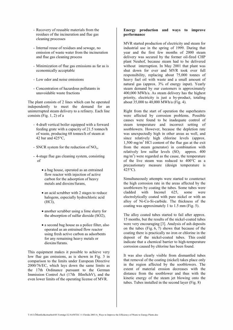
- Recovery of reusable materials from the residues of the incineration and flue gas cleaning processes
- Internal reuse of residues and sewage, no emission of waste water from the incineration and flue gas cleaning process
- Minimization of flue gas emissions as far as iseconomically acceptable
- Low odor and noise emissions
- Concentration of hazardous pollutants in unavoidable waste fractions
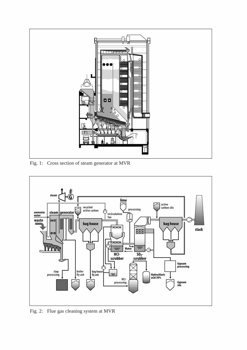
The plant consists of 2 lines which can be operatedindependently to meet the demand for anuninterrupted steam delivery to a refinery. Each lineconsists (Fig. 1, 2) of a
- 4-draft vertical boiler equipped with a forwardfeeding grate with a capacity of 21.5 tonnes/h of waste, producing 68 tonnes/h of steam at 42 bar and 425°C,
- SNCR system for the reduction of NOx,
- 4-stage flue gas cleaning system, consisting of
� a bag house, operated as an entrainedflow reactor with injection of active carbon for the adsorption of heavy metals and dioxins/furans,
� an acid scrubber with 2 stages to reducehalogens, especially hydrochloric acid (HCl),
� another scrubber using a lime slurry forthe absorption of sulfur dioxide (SO2),
� a second bag house as a police filter, alsooperated as an entrained flow reactor using fresh active carbon as adsorbents for any remaining heavy metals or dioxins/furans.
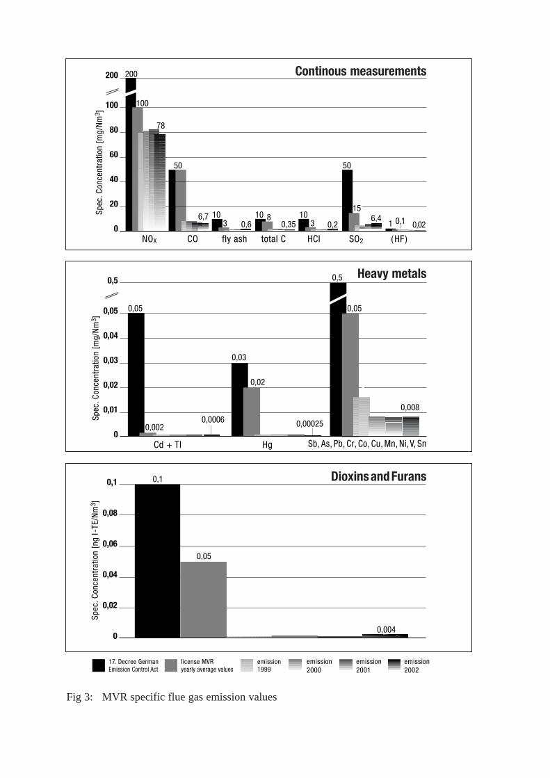
This equipment makes it possible to achieve verylow flue gas emissions, as is shown in Fig. 3 incomparison to the limits under European Directive2000/76/EC, which lays down the same limits asthe 17th Ordinance pursuant to the GermanImmission Control Act (17th BImSchV), and theeven lower limits of the operating license of MVR.
Energy production and ways to improveperformance
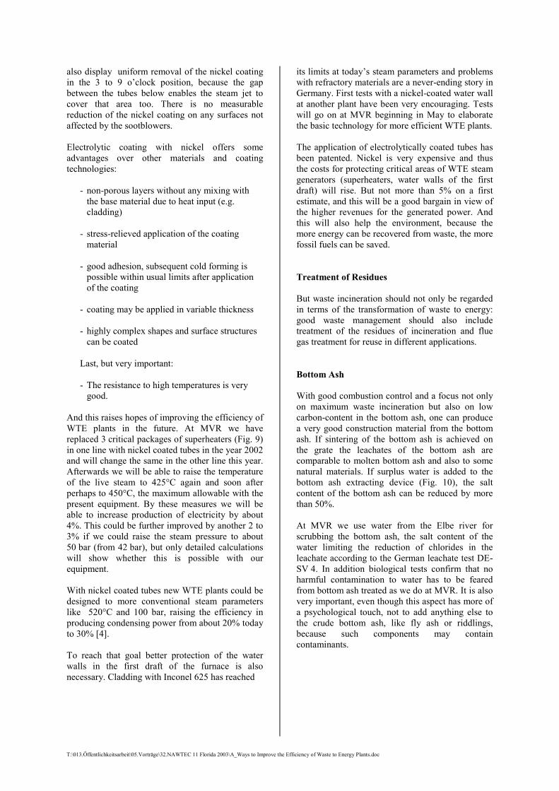
MVR started production of electricity and steam forindustrial use in the spring of 1999. During thatyear and the first few months of 2000 steamdelivery was secured by the former oil-fired CHPplant Neuhof, because steam had to be deliveredwithout interruption. In May 2001 that plant wasshut down for ever and MVR took over fullresponsibility, replacing about 75,000 tonnes ofheavy fuel oil with waste and a small amount ofnatural gas (approx. 3% of energy input). Yearlysteam demand by our customers is approximately400,000 MWh/a. As steam delivery has the highestpriority, electricity is just a by-product, totalingabout 35,000 to 40,000 MWh/a (Fig. 4).
Right from the start of operation the superheaterswere affected by corrosion problems. Possiblecauses were found to be inadequate control ofsteam temperature and incorrect setting ofsootblowers. However, because the depletion ratewas unexpectedly high in other areas as well, andsince relatively high chlorine levels (approx.1,500 mg/m3 HCl content of the flue gas at the exitfrom the steam generator) in combination withrelatively low sulfur levels (SO2 approx. 400mg/m3) were regarded as the cause, the temperatureof the live steam was reduced to 400°C as aprecautionary measure (design temperature is425°C).
Simultaneously attempts were started to counteractthe high corrosion rate in the areas affected by thesootblowers by coating the tubes. Some tubes werecladded with Inconel 625, some wereelectrolytically coated with pure nickel or with analloy of Ni-Co-Si-carbide. The thickness of thecoating was approximately 1 to 1.5 mm (Fig. 5).
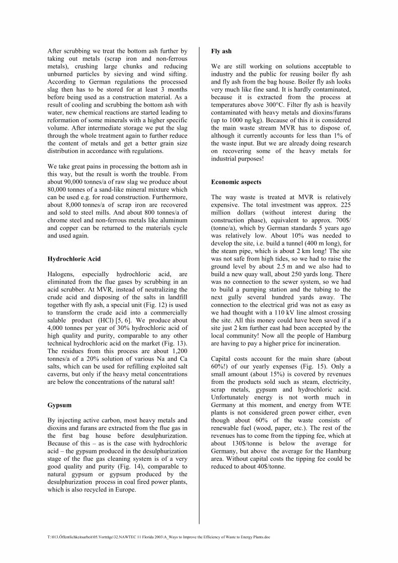
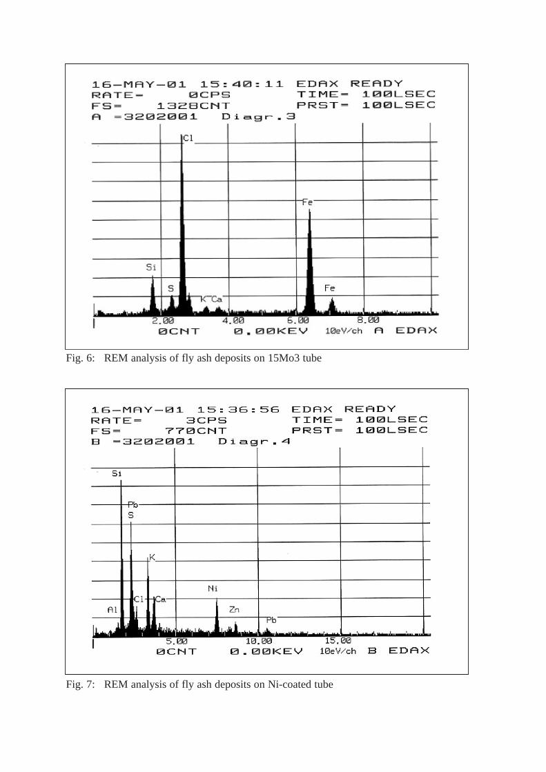
The alloy coated tubes started to fail after approx.15 months, but the results of the nickel-coated tubeswere very encouraging [3]. Analysis of ash depositson the tubes (Fig. 6, 7) shows that because of thecoating there is practically no iron or chlorine in thedeposit of the nickel-coated tubes. This couldindicate that a chemical barrier to high-temperaturecorrosion caused by chlorine has been found.
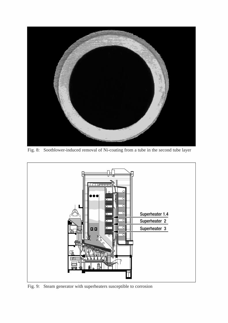
It was also clearly visible from dismantled tubesthat removal of the coating (nickel) takes place onlyin the region affected by the sootblowers. Theextent of material erosion decreases with thedistance from the sootblower and thus with thekinetic energy of the steam jet blowing onto thetubes. Tubes installed in the second layer (Fig. 8)
T:\013.Öffentlichkeitsarbeit\05.Vorträge\32.NAWTEC 11 Florida 2003\A_Ways to Improve the Efficiency of Waste to Energy Plants.doc
also display uniform removal of the nickel coatingin the 3 to 9 o’clock position, because the gapbetween the tubes below enables the steam jet tocover that area too. There is no measurablereduction of the nickel coating on any surfaces notaffected by the sootblowers.
Electrolytic coating with nickel offers someadvantages over other materials and coatingtechnologies:
- non-porous layers without any mixing with the base material due to heat input (e.g. cladding)
- stress-relieved application of the coating material
- good adhesion, subsequent cold forming is possible within usual limits after application of the coating
- coating may be applied in variable thickness
- highly complex shapes and surface structures can be coated
Last, but very important:
- The resistance to high temperatures is very good.
And this raises hopes of improving the efficiency ofWTE plants in the future. At MVR we havereplaced 3 critical packages of superheaters (Fig. 9)in one line with nickel coated tubes in the year 2002and will change the same in the other line this year.Afterwards we will be able to raise the temperatureof the live steam to 425°C again and soon afterperhaps to 450°C, the maximum allowable with thepresent equipment. By these measures we will beable to increase production of electricity by about4%. This could be further improved by another 2 to3% if we could raise the steam pressure to about50 bar (from 42 bar), but only detailed calculationswill show whether this is possible with ourequipment.
With nickel coated tubes new WTE plants could bedesigned to more conventional steam parameterslike 520°C and 100 bar, raising the efficiency inproducing condensing power from about 20% todayto 30% [4].
To reach that goal better protection of the waterwalls in the first draft of the furnace is alsonecessary. Cladding with Inconel 625 has reached
its limits at today’s steam parameters and problemswith refractory materials are a never-ending story inGermany. First tests with a nickel-coated water wallat another plant have been very encouraging. Testswill go on at MVR beginning in May to elaboratethe basic technology for more efficient WTE plants.
The application of electrolytically coated tubes hasbeen patented. Nickel is very expensive and thusthe costs for protecting critical areas of WTE steamgenerators (superheaters, water walls of the firstdraft) will rise. But not more than 5% on a firstestimate, and this will be a good bargain in view ofthe higher revenues for the generated power. Andthis will also help the environment, because themore energy can be recovered from waste, the morefossil fuels can be saved.
Treatment of Residues
But waste incineration should not only be regardedin terms of the transformation of waste to energy:good waste management should also includetreatment of the residues of incineration and fluegas treatment for reuse in different applications.
Bottom Ash
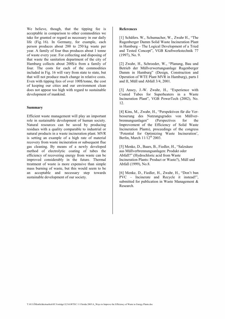
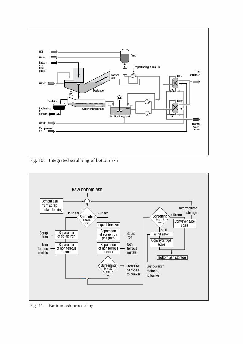
With good combustion control and a focus not onlyon maximum waste incineration but also on lowcarbon-content in the bottom ash, one can producea very good construction material from the bottomash. If sintering of the bottom ash is achieved onthe grate the leachates of the bottom ash arecomparable to molten bottom ash and also to somenatural materials. If surplus water is added to thebottom ash extracting device (Fig. 10), the saltcontent of the bottom ash can be reduced by morethan 50%.
At MVR we use water from the Elbe river forscrubbing the bottom ash, the salt content of thewater limiting the reduction of chlorides in theleachate according to the German leachate test DE-SV 4. In addition biological tests confirm that noharmful contamination to water has to be fearedfrom bottom ash treated as we do at MVR. It is alsovery important, even though this aspect has more ofa psychological touch, not to add anything else tothe crude bottom ash, like fly ash or riddlings,because such components may containcontaminants.
T:\013.Öffentlichkeitsarbeit\05.Vorträge\32.NAWTEC 11 Florida 2003\A_Ways to Improve the Efficiency of Waste to Energy Plants.doc
After scrubbing we treat the bottom ash further bytaking out metals (scrap iron and non-ferrousmetals), crushing large chunks and reducingunburned particles by sieving and wind sifting.According to German regulations the processedslag then has to be stored for at least 3 monthsbefore being used as a construction material. As aresult of cooling and scrubbing the bottom ash withwater, new chemical reactions are started leading toreformation of some minerals with a higher specificvolume. After intermediate storage we put the slagthrough the whole treatment again to further reducethe content of metals and get a better grain sizedistribution in accordance with regulations.
We take great pains in processing the bottom ash inthis way, but the result is worth the trouble. Fromabout 90,000 tonnes/a of raw slag we produce about80,000 tonnes of a sand-like mineral mixture whichcan be used e.g. for road construction. Furthermore,about 8,000 tonnes/a of scrap iron are recoveredand sold to steel mills. And about 800 tonnes/a ofchrome steel and non-ferrous metals like aluminumand copper can be returned to the materials cycleand used again.
Hydrochloric Acid
Halogens, especially hydrochloric acid, areeliminated from the flue gases by scrubbing in anacid scrubber. At MVR, instead of neutralizing thecrude acid and disposing of the salts in landfilltogether with fly ash, a special unit (Fig. 12) is usedto transform the crude acid into a commerciallysalable product (HCl) [5, 6]. We produce about4,000 tonnes per year of 30% hydrochloric acid ofhigh quality and purity, comparable to any othertechnical hydrochloric acid on the market (Fig. 13).The residues from this process are about 1,200tonnes/a of a 20% solution of various Na and Casalts, which can be used for refilling exploited saltcaverns, but only if the heavy metal concentrationsare below the concentrations of the natural salt!
Gypsum
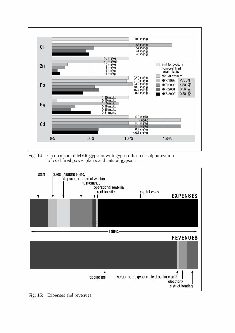
By injecting active carbon, most heavy metals anddioxins and furans are extracted from the flue gas inthe first bag house before desulphurization.Because of this – as is the case with hydrochloricacid – the gypsum produced in the desulphurizationstage of the flue gas cleaning system is of a verygood quality and purity (Fig. 14), comparable tonatural gypsum or gypsum produced by thedesulphurization process in coal fired power plants,which is also recycled in Europe.
Fly ash
We are still working on solutions acceptable toindustry and the public for reusing boiler fly ashand fly ash from the bag house. Boiler fly ash looksvery much like fine sand. It is hardly contaminated,because it is extracted from the process attemperatures above 300°C. Filter fly ash is heavilycontaminated with heavy metals and dioxins/furans(up to 1000 ng/kg). Because of this it is consideredthe main waste stream MVR has to dispose of,although it currently accounts for less than 1% ofthe waste input. But we are already doing researchon recovering some of the heavy metals forindustrial purposes!
Economic aspects
The way waste is treated at MVR is relativelyexpensive. The total investment was approx. 225million dollars (without interest during theconstruction phase), equivalent to approx. 700$/(tonne/a), which by German standards 5 years agowas relatively low. About 10% was needed todevelop the site, i.e. build a tunnel (400 m long), forthe steam pipe, which is about 2 km long! The sitewas not safe from high tides, so we had to raise theground level by about 2.5 m and we also had tobuild a new quay wall, about 250 yards long. Therewas no connection to the sewer system, so we hadto build a pumping station and the tubing to thenext gully several hundred yards away. Theconnection to the electrical grid was not as easy aswe had thought with a 110 kV line almost crossingthe site. All this money could have been saved if asite just 2 km further east had been accepted by thelocal community! Now all the people of Hamburgare having to pay a higher price for incineration.
Capital costs account for the main share (about60%!) of our yearly expenses (Fig. 15). Only asmall amount (about 15%) is covered by revenuesfrom the products sold such as steam, electricity,scrap metals, gypsum and hydrochloric acid.Unfortunately energy is not worth much inGermany at this moment, and energy from WTEplants is not considered green power either, eventhough about 60% of the waste consists ofrenewable fuel (wood, paper, etc.). The rest of therevenues has to come from the tipping fee, which atabout 130$/tonne is below the average forGermany, but above the average for the Hamburgarea. Without capital costs the tipping fee could bereduced to about 40$/tonne.
T:\013.Öffentlichkeitsarbeit\05.Vorträge\32.NAWTEC 11 Florida 2003\A_Ways to Improve the Efficiency of Waste to Energy Plants.doc
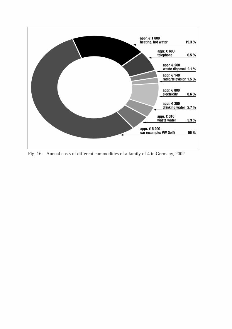
We believe, though, that the tipping fee isacceptable in comparison to other commodities wetake for granted or regard as necessary in our dailylife (Fig. 16). In Germany, for example, eachperson produces about 200 to 250 kg waste peryear. A family of four thus produces about 1 tonneof waste every year. For collecting and disposing ofthat waste the sanitation department of the city ofHamburg collects about 200$/a from a family offour. The costs for each of the commoditiesincluded in Fig. 16 will vary from state to state, butthat will not produce much change in relative costs.Even with tipping fees of over 100$/tonne, the costof keeping our cities and our environment cleandoes not appear too high with regard to sustainabledevelopment of mankind.
Summary
Efficient waste management will play an importantrole in sustainable development of human society.Natural resources can be saved by producingresidues with a quality comparable to industrial ornatural products in a waste incineration plant. MVRis setting an example of a high rate of materialrecovery from waste incineration or subsequent fluegas cleaning. By means of a newly developedmethod of electrolytic coating of tubes theefficiency of recovering energy from waste can beimproved considerably in the future. Thermaltreatment of waste is more expensive than simplemass burning of waste, but this would seem to bean acceptable and necessary step towardssustainable development of our society.
References
[1] Schäfers. W., Schumacher, W., Zwahr H., “TheRugenberger Damm Solid Waste Incineration Plantin Hamburg – The Logical Development of a Triedand Tested Concept”, VGB Kraftwerkstechnik 77(1997), No. 9.
[2] Zwahr, H., Schroeder, W., “Planung, Bau undBetrieb der Müllverwertungsanlage RugenbergerDamm in Hamburg” (Design, Construction andOperation of WTE Plant MVR in Hamburg), parts Iand II, Müll und Abfall 3/4, 2001.
[3] Ansey, J.-W. Zwahr, H., “Experience withCoated Tubes for Superheaters in a WasteIncineration Plant”, VGB PowerTech (2002), No.12.
[4] Kins, M., Zwahr, H., “Perspektiven für die Ver-besserung des Nutzungsgrades von Müllver-brennungsanlagen” (Perspectives for theImprovement of the Efficiency of Solid WasteIncineration Plants), proceedings of the congress‘Potential for Optimizing Waste Incineration’,Berlin, March 11/12th 2003.
[5] Menke, D., Baars, B., Fiedler, H., “Salzsäureaus Müllverbrennungsanlagen: Produkt oderAbfall?” (Hydrochloric acid from WasteIncineration Plants: Product or Waste?), Müll undAbfall (1999), No.8.
[6] Menke, D., Fiedler, H., Zwahr, H., “Don’t banPVC – Incinerate and Recycle it instead!”,submitted for publication in Waste Management &Research.
Seite 9 von 16
Water
Hydrochloricacid 30%
Gypsumsilo
Gypsumprocessing
SNCR
Gsteam
steam generator
Fig. 1: Cross section of steam generator at MVR
Fig. 2: Flue gas cleaning system at MVR
Seite 10 von 16
200
100
80
60
40
20
0
200
100
50
6,7 103 30,6
10 80,35
fly ashCO (HF)total C HClNOX SO2
0,2 0,1 0,0210
50
156,4
1
Spec
. Con
cent
ratio
n [m
g/N
m3 ]
78
0,5
0,05
0,04
0,03
0,02
0,01
0
0,05
0,03
0,05
0,5
Cd + Tl Sb, As, Pb, Cr, Co, Cu, Mn, Ni, V, SnHg
Spec
. Con
cent
ratio
n [m
g/N
m3 ]
0,002
0,02
0,000250,00060,008
0,1
0,08
0,06
0,04
0,02
0
0,1
Dioxine / Furane
Spec
. Con
cent
ratio
n [n
g I-
TE/N
m3 ]
0,004
0,05
17. Decree GermanEmission Control Act
license MVRyearly average values
emission 2000
emission 2001
emission 2002
emission 1999
Fig 3: MVR specific flue gas emission values
Heavy metals
Continous measurements
DioxinsandFurans

Seite 11 von 16
Fig. 4: Steam and electricity by MVR Jan. 2000 until Dec. 2002
Fig. 5: Tube coated electrolytically with nickel
Stea
m M
Wh
Elec
tric
ity M
Wh
01 /
00
03 /
00
06 /
00
09 /
00
12 /
00
03 /
01
06 /
01
09 /
01
12 /
01
03 /
02
12 /
02
06 /
02
09 /
02
10 000
0 0
1 000
2 000
3 000
4 000
5 000
6 000
5 000
35 000
30 000
25 000
20 000
15 000
40 000
45 000
50 000
Steam
Electricity
Seite X von 16
Fig. 6: REM analysis of fly ash deposits on 15Mo3 tube
Fig. 7: REM analysis of fly ash deposits on Ni-coated tube
Seite X von 16
Superheater 1.4
Superheater 2
Superheater 3
Fig. 8: Sootblower-induced removal of Ni-coating from a tube in the second tube layer
Fig. 9: Steam generator with superheaters susceptible to corrosion
Seite 12 von 16
Fig. 10: Integrated scrubbing of bottom ash
Fig. 11: Bottom ash processing
HClTank
Filter
Filter
Proportioning pump HCl
Bottomash
Deslagger
Purification tank
Water
Bottomashfromgrate
Water
Container
Sedimentation tank
Water Processwaterbasin
HClscrubber
Sedimentsto bunker
Compressedair
MM
Raw bottom ash
Screening0 to 32
mm
0 to 32 mm > 32 mm
Scrapiron
Scrapiron
Impact breaker
Separationof non ferrous
metals
Separationof non ferrous
metals
Separationof scrap iron
<10mm
>10
Non ferrousmetals
Non ferrousmetals
Oversizeparticlesto bunker
Wind sifter
Conveyor typescale
Bottom ash storage
Light-weight material, to bunker
Intermediatestorage
Screening0 to 32
mm
Screening0 to 10
mm Conveyor typescale
Separationof scrap iron
(magnet)
Bottom ash from scrap metal cleaning

Seite 13 von 16
Activecarbonfilter
Filter
Halogen-scrubber
Fluorideseparator
Distillationcolumn
Absorber
Hol-der
from CaCl2 Concen-tration
to CaCl2 Concen-tration
Conden-sate
Conden-sate
SteamSodium-thiosulfate
Na2S2O3
Sodium-hypo-
chloriteNaOCl
Soda lyeNaOH
Air
Coolingwater
Desalinatedwater
Alu-minium-chloride
Neutrali-zation,Mixedsalts
Halogen-stripper
Tank Evapo-rator
Evapo-rator
Air
Raw acid from the gas cleaning
Tank
Loading of HCl
Fig. 12: HCl-rectification unit
Fig. 13: Comparison of hydrochloric acid produced by MVR with HCl according to European standard EN 939
0%
EOX
Se
Sb
Ni
50%
6.1 mg/l
1.8 mg/l
0.36 mg/l
1.1 mg/l
0.06
0.022
0.1 0.1
0.01 0.02 0.011
Hg 0.18 mg/l
Cr 1.1 mg/l
< 0.05 < 0.005 < 0.005
Pb 1.1 mg/l 0.14
Cd 0.36 mg/l
0.2 0.0460.102
As 1.1 mg/l 0.13
Fe 61 mg/l
mg/l
mg/l
mg/l
mg/l
mg/l
mg/l
mg/l
mg/l
mg/l
mg/l 1.7
100%
EN 939, Type 1MVR 1999MVR 2000MVR 2001MVR 2002
EN 939
Concentration32% HCl
< 0.05
< 0.05 < 0.03
0.026 0.017 0.008 0.010 0.002 0.002 0.004 0.008
0.037 0.0130.005
0.024
0.0030.0060.00060.0006
0.0530.0720.045
0.032
0.004
Seite 14 von 16
100%
capital costs
maintenance
capital costsrent for site
staff taxes, insurance, etc.disposal or reuse of wastes
EXPENSES
tipping fee
REVENUES
scrap metal, gypsum, hydrochloric acidelectricitydistrict heating
operational material
Hg
Cd
0%
Cl-
Zn
Pb
50%
100 mg/kg
22.0 mg/kg
0.3 mg/kg
0.3 mg/kg0.5 mg/kg0.2 mg/kg
< 0.2 mg/kg
0.5 mg/kg
0.09 mg/kg
21.0 mg/kg
50 mg/kg40 mg/kg
1.10 mg/kg0.36 mg/kg0.26 mg/kg0.51 mg/kg
23.0 mg/kg13.0 mg/kg15.0 mg/kg
8.6 mg/kg
10 mg/kg8 mg/kg3 mg/kg5 mg/kg
156 mg/kg54 mg/kg44 mg/kg48 mg/kg
150%100%
limit for gypsum from coal fired power plants natural gypsumMVR 1999MVR 2000 MVR 2001 MVR 2002
PCDD/F4.500.360.20 ng
l-TEQ
/kg
1.30 mg/kg
Fig. 14: Comparison of MVR-gypsum with gypsum from desulphurization of coal fired power plants and natural gypsum
Fig. 15: Expenses and revenues
Seite 15 von 16
appr. € 1 800 heating, hot water 19.3 %
appr. € 600 telephone 6.5 %
appr. € 200 waste disposal 2.1 %
appr. € 140 radio/television 1.5 %
appr. € 800 electricity 8.6 %
appr. € 250 drinking water 2.7 %
appr. € 310 waste water 3.3 %
appr. € 5 200 car (example: VW Golf) 56 %
Fig. 16: Annual costs of different commodities of a family of 4 in Germany, 2002