importance of understanding 3-d kinematic controls in...
TRANSCRIPT
1 INTRODUCTION
The global demand for base metals, combined with diminishing near surface resources, has influenced a number of deep, open pit mining operations to consider the transition to underground mass mining operations to recover the deeper reaches of an orebody extending the life of the operation. As a function of these larger, more complicated mine designs, the potential for complex pit slope movements to evolve into large scale failures creates cause for both safety and economic concerns.
Monitoring programs involving geodetic prisms form a key component of most slope stability programs for modern open pits. Most pits, active or inactive, have a program in place to record slope displacement providing data that may be used to quantify the nature and extent of the hazard, the kinematics and stability state of the slope, or to provide early warning of an impending failure. Issues of uncertainty relating to the geological conditions, slope kinematics, and failure modes provide obstacles that contribute to a lack of understanding of the potential for failure.
At the same time, the techniques used for monitoring and forecasting pit wall failures are largely empirical, relying on surface-based point measurements of displacements monitored over time. This data is then extrapolated or analyzed for accelerations that exceed set thresholds based on earlier patterns (e.g. Fukuzono 1985). These approaches are ‘holistic’ and disregard details pertaining to the underlying geology, controlling geological structures and slope failure mechanism.
Importance of understanding 3-D kinematic controls in the review of displacement monitoring of deep open pits above underground mass mining operations
J. Severin & E. Eberhardt University of British Columbia, Vancouver, Canada
S. Ngidi Palabora Mining Company, Phalaborwa, South Africa
A. Stewart Piteau Associates Engineering Ltd., Vancouver, Canada
ABSTRACT: Surface mining operations are increasingly involving the design and development of deeper and larger open pits, often with plans to transition into underground mass mining operations. Experiences at the Palabora Mine in South Africa demonstrate the complex interactions between underground workings and the steep slopes above that may lead to slope movements that potentially pose safety and economic concerns. To properly assess the rock mass response to these interactions for planning of future developments, understanding the controlling influence of geological and geomechanical structures is crucial. Preliminary results are presented from a detailed review of historical slope monitoring data from the Palabora Mine, before and after the initiation of block caving 400-m beneath a 800-m deep pit. This paper demonstrates that a detailed analysis of geology and monitoring data can be used to better understand the kinematic controls of complex rock slope displacements and interactions between open pits and underground mines. This investigative treatment of the monitoring data is important in understanding the failure mechanisms prior to undertaking sophisticated 3-D numerical models.
ROCKENG09: Proceedings of the 3rd CANUS Rock Mechanics Symposium, Toronto, May 2009 (Ed: M.Diederichs and G. Grasselli)
PAPER 3914 1
Often, large-scale geological structures (e.g. major fault zones) play a dominant role in controlling the kinematics and stability of large pit slopes. With the added consideration of complex rock mass stress-strain interactions in response to rock mass failure and underground mass mining operations, the resulting 3-D deformation pattern of the pit slope becomes progressively more and more difficult to interpret with respect to how it will evolve. This creates a serious obstacle in the stability assessment of the slope or setting early warning alarm thresholds if the pit is in operation (e.g. during scavenging operations), near sensitive surface structures located near the crest of the pit slope, or underground. A number of cases exist where sudden collapses of cave backs, crown pillars, etc., have occurred due to unexpected geological structures or unexpected rock mass behaviour, including the hangingwall wedge failure at the Kidd Creek mine in Canada that propagated from 610-m depth to surface (Board et al. 2000), the 800-m high pit wall failure at Palabora in South Africa (Brummer et al. 2006), or the fatal air blast caused by sudden caving at the Northparkes mine in Australia (Hebblewhite 2003).
To contend with these complex interactions, numerical modeling offers a powerful means to break down problems into their constituent parts and analyse cause and effect relationships and their evolution. Techniques such as the distinct-element method (e.g. UDEC/3DEC; Itasca 1999, 2003) allow for the explicit inclusion of geological structures and rock mass heterogeneity. However, in order to effectively model the rock slope, a tight control on the representation of the geology is required for which monitoring data can be used as an important constraint. Yet the interpretation of monitoring data is far from straight forward and can be affected by the same issues of rock mass complexity and variability as affects the numerical models the data are meant to constrain.
2 MONITORING OF PIT WALL BEHAVIOUR 2.1 Current State of Practice
For slope monitoring to be effective, the data must serve an investigative role before it can serve a predictive role, allowing an understanding of the slope behaviour to be established in order to properly define alarm thresholds. Thus the function of the monitoring network can be seen as serving two purposes (Moore et al. 1991):
(i) Investigative Monitoring: To provide an understanding of the slope and thus avoid future large-scale stability issues.
(ii) Predictive Monitoring: To provide a warning of a change in behaviour and thus enable the possibility of limiting damage or intervening to prevent hazardous sliding.
Monitoring systems commonly used in an open pit environment are categorized by Jarosz & Wanke (2003) as surveying techniques or geotechnical methods. Surveying techniques include total station/geodetic monitoring of prisms, use of GPS receivers, slope stability radar, etc., used to determine absolute positions. Geotechnical methods employ specialized instrumentation to measure differential displacements over a short distance, and include extensometers, tiltmeters, inclinometers, etc. Examples of strategies employed at different mines based on these methods include those by Logan et al. (1993), Loubser (1993), Little (2006), Brown et al. (2007), and Day & Seery (2007), amongst others.
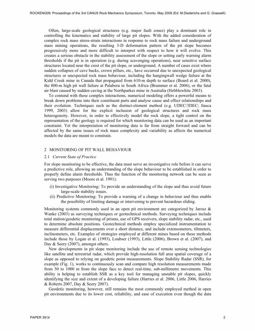
New developments in pit slope monitoring include the use of remote sensing technologies like satellite and terrestrial radar, which provide high-resolution full area spatial coverage of a slope as opposed to relying on geodetic point measurements. Slope Stability Radar (SSR), for example (Fig. 1), works to continuously scan and compare high resolution measurements made from 50 to 1000 m from the slope face to detect real-time, sub-millimetre movements. This ability is helping to establish SSR as a key tool for managing unstable pit slopes, quickly identifying the size and extent of a developing failure (Harries et al. 2006, Little 2006, Harries & Roberts 2007, Day & Seery 2007).
Geodetic monitoring, however, still remains the most commonly employed method in open pit environments due to its lower cost, reliability, and ease of execution even though the data
ROCKENG09: Proceedings of the 3rd CANUS Rock Mechanics Symposium, Toronto, May 2009 (Ed: M.Diederichs and G. Grasselli)
PAPER 3914 2
can sometimes incorporate measurement errors. The geodetic monitoring of numerous prisms installed on multiple benches is now routinely undertaken using robotic total stations, with more recent efforts being to combine these systems with global navigation satellite systems (Brown et al. 2007). Monitoring through GPS receivers has also been seen as an answer to large open pit projects where the pit diameter exceeds 1 km and refraction and pointing errors start to limit the effectiveness of total station measurements. Bond et al. (2007) list the advantages of GPS monitoring over other geodetic technologies as including continuous and high accuracy displacement detection, together with not requiring line of sight between stations, providing 3-D position information, and making millimetre-level data possible for baselines up to 10 km in length. Although these authors report operating in a harsh environment like open pit mining as being another advantage, experiences at the Palabora mine have suggested otherwise. A GPS-based system installed in November 2004 proved unreliable due to non-systematic interruptions or system shut downs in response to high pit temperatures that could exceed 45°C. As noted by Dunnicliff (1988) and Eberhardt et al. (2008), instrument reliability is of paramount importance, especially if it is part of a system being relied upon for early warning monitoring.
Figure 1. GroundProbe’s Slope Stability Radar (SSR) system showing the continuous monitoring of millimetre-scale movements across the entire face of an unstable open pit slope (after Harries et al. 2006).
2.2 Investigative Monitoring
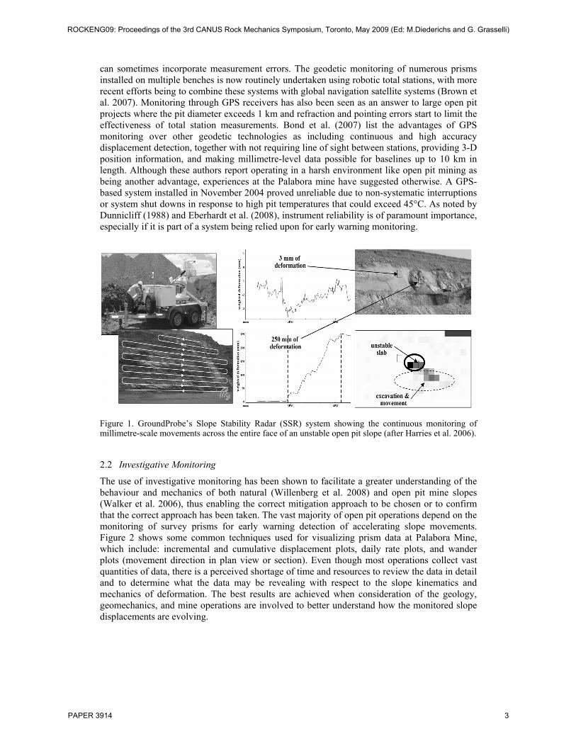
The use of investigative monitoring has been shown to facilitate a greater understanding of the behaviour and mechanics of both natural (Willenberg et al. 2008) and open pit mine slopes (Walker et al. 2006), thus enabling the correct mitigation approach to be chosen or to confirm that the correct approach has been taken. The vast majority of open pit operations depend on the monitoring of survey prisms for early warning detection of accelerating slope movements. Figure 2 shows some common techniques used for visualizing prism data at Palabora Mine, which include: incremental and cumulative displacement plots, daily rate plots, and wander plots (movement direction in plan view or section). Even though most operations collect vast quantities of data, there is a perceived shortage of time and resources to review the data in detail and to determine what the data may be revealing with respect to the slope kinematics and mechanics of deformation. The best results are achieved when consideration of the geology, geomechanics, and mine operations are involved to better understand how the monitored slope displacements are evolving.
ROCKENG09: Proceedings of the 3rd CANUS Rock Mechanics Symposium, Toronto, May 2009 (Ed: M.Diederichs and G. Grasselli)
PAPER 3914 3
Figure 2. Examples of a) cumulative rate plot, and b) wander plot used at the Palabora Mine (based on Piteau, 2005).
2.3 Predictive Monitoring
A majority of the slopes within an open pit environment are monitored to ensure the safety of workers and equipment, and to evaluate the effectiveness of any mitigative measures undertaken (e.g. slope drainage). Early warning thresholds are usually set by trial and error, or over time, the experience of those involved. In turn, the data are assessed by extrapolating the measured displacement-time series to detect accelerations that exceed set thresholds. One such example is the inverse velocity method (Fukuzono 1985, Rose & Hungr 2007). It must be noted that these approaches are generally applied independent of the acting slope failure mechanism or its kinematic controls. As such, the triggering of faulty alarms or uncertainty over misleading instrument readings is a frequent problem. Once an alarm is triggered, the mine will shut down operations in the unsafe area: if a failure is realized, the procedure is deemed a success (e.g. Day & Seery 2007); if a failure is not realized, the procedure results in costly down time, delays to production schedules and diminished confidence in the system.
3 PALABORA MINE SITE
3.1 Mine Characteristics and Production
The Palabora Open Pit Mine, located approximately 500 km northeast of Johannesburg, South Africa, began production in 1966. In 2002, as the pit neared completion, it measured approximately 800 m in depth and 1650 m across. Inter ramp angles ranged from 37° in the upper weathered rock to 58° in the competent lithologies at the base of the pit (Moss et al. 2006). A transition to an underground block cave mining operation commensed in April 2001 with underground production increasing gradually until full production was achieved in May 2005. Ramp-scavenging operations were undertaken in the pit between 2002 and 2003 to retrieve orphaned ore to augment the underground production. Important caving milestones in relation to its effect on the surface environment include: Dec. 2002, the crown pillar was noted to be de-stressed (based on microseismic data); Mar. 2003, hydraulic conductivity was observed between the pit bottom and underground cave; and Dec. 2003 (estimated), cave break through into the pit.
The current production level of the underground mine, shown in Figure 3 (Brummer et al. 2006), is located approximately 1,200 m below the surface and 400 m below the final pit bottom. The production level currently consists of 20 cross-cuts giving a footprint of 650 m long by 250 m wide.
ROCKENG09: Proceedings of the 3rd CANUS Rock Mechanics Symposium, Toronto, May 2009 (Ed: M.Diederichs and G. Grasselli)
PAPER 3914 4
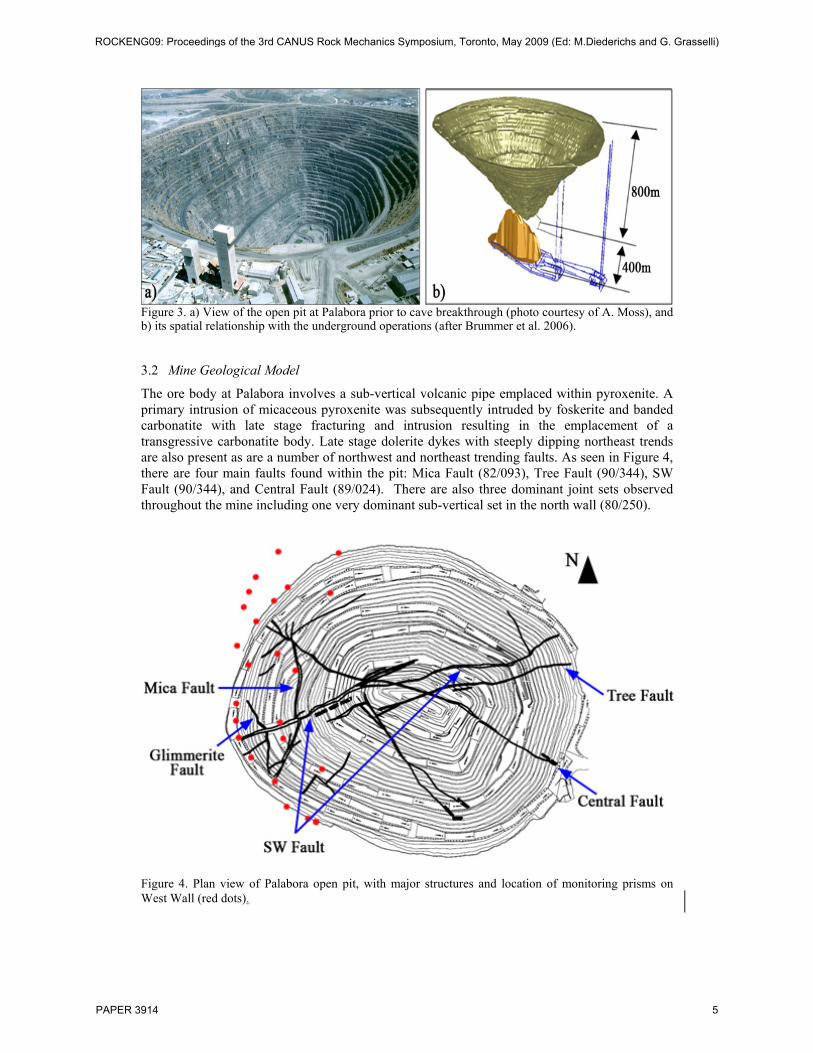
Figure 3. a) View of the open pit at Palabora prior to cave breakthrough (photo courtesy of A. Moss), and b) its spatial relationship with the underground operations (after Brummer et al. 2006).
3.2 Mine Geological Model
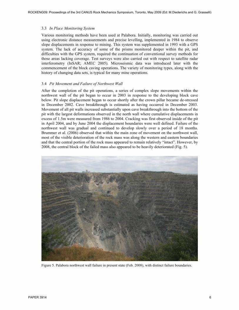
The ore body at Palabora involves a sub-vertical volcanic pipe emplaced within pyroxenite. A primary intrusion of micaceous pyroxenite was subsequently intruded by foskerite and banded carbonatite with late stage fracturing and intrusion resulting in the emplacement of a transgressive carbonatite body. Late stage dolerite dykes with steeply dipping northeast trends are also present as are a number of northwest and northeast trending faults. As seen in Figure 4, there are four main faults found within the pit: Mica Fault (82/093), Tree Fault (90/344), SW Fault (90/344), and Central Fault (89/024). There are also three dominant joint sets observed throughout the mine including one very dominant sub-vertical set in the north wall (80/250).
Figure 4. Plan view of Palabora open pit, with major structures and location of monitoring prisms on West Wall (red dots).
ROCKENG09: Proceedings of the 3rd CANUS Rock Mechanics Symposium, Toronto, May 2009 (Ed: M.Diederichs and G. Grasselli)
PAPER 3914 5
3.3 In Place Monitoring System
Various monitoring methods have been used at Palabora. Initially, monitoring was carried out using electronic distance measurements and precise levelling, implemented in 1984 to observe slope displacements in response to mining. This system was supplemented in 1993 with a GPS system. The lack of accuracy of some of the prisms monitored deeper within the pit, and difficulties with the GPS system, required the continuation of conventional survey methods for those areas lacking coverage. Test surveys were also carried out with respect to satellite radar interferometry (InSAR; AMEC 2005). Microseismic data was introduced later with the commencement of the block caving operations. The variety of monitoring types, along with the history of changing data sets, is typical for many mine operations.
3.4 Pit Movement and Failure of Northwest Wall
After the completion of the pit operations, a series of complex slope movements within the northwest wall of the pit began to occur in 2003 in response to the developing block cave below. Pit slope displacement began to occur shortly after the crown pillar became de-stressed in December 2002. Cave breakthrough is estimated as having occurred in December 2003. Movement of all pit walls increased substantially upon cave breakthrough into the bottom of the pit with the largest deformations observed in the north wall where cumulative displacements in excess of 1.5m were measured from 1986 to 2004. Cracking was first observed inside of the pit in April 2004, and by June 2004 the displacement boundaries were well defined. Failure of the northwest wall was gradual and continued to develop slowly over a period of 18 months. Brummer et al. (2006) observed that within the main zone of movement on the northwest wall, most of the visible deterioration of the rock mass was along the western and eastern boundaries and that the central portion of the rock mass appeared to remain relatively “intact”. However, by 2008, the central block of the failed mass also appeared to be heavily deteriorated (Fig. 5).
Figure 5. Palabora northwest wall failure in present state (Feb. 2008), with distinct failure boundaries.
ROCKENG09: Proceedings of the 3rd CANUS Rock Mechanics Symposium, Toronto, May 2009 (Ed: M.Diederichs and G. Grasselli)
PAPER 3914 6

4 PIT DISPLACEMENT HISTORY AT PALABORA
Due to planned future underground developments of the block cave at Palabora, understanding the kinematic state and key geological controls within the pit is of primary importance. Here, the analysis undertaken only considers the large-scale structures such as faults, shear zones, and dykes found within the pit. Prisms around the pit were plotted with displacement rates, cumulative displacement, and direction of displacement with respect to these major features. From this, any potential relationships between the movements observed and the geologic features present could be resolved. For preliminary review, the rock masses and different structural domains were treated as non-deforming blocks.
The assessment included all geodetic data collected between 1984 and 2004. For the purpose of this paper, review of the West Wall is presented for the time period prior to block cave mining, as well as that before, during and after the failure of the northwest wall.
4.1 Pre-Block Cave Displacements (1984-2001)
Prior to caving, total displacement in the west wall averaged between 0.03 and 0.05 mm/day (between 1984 and 2001) with incremental rates up to 2.3 mm/day. Reviews of the prism rates for the other pit walls reveal that the rates were fairly consistent throughout the pit. The review showed that prisms on the northwest wall (near the intersection of the Mica and Central Faults, see Fig. 4) underwent more displacement than in other parts of the west wall. Incremental displacement values are based on measured horizontal and vertical displacement measurements. Review of these constituent vectors (horizontal and vertical) show that the incremental vertical displacement rates (0.18 to 0.36 mm/day) were higher than the incremental horizontal displacement rates (0.10 to 0.15 mm/day); however, for all prism data, vertical displacement was dominated by both up and down movement, suggesting that both strain relief in response to removal of overburden (rebound) and downward relaxation of the slopes towards the pit were active components. In general, larger cumulative vertical displacements (downward) were observed at prisms located within the weaker rock types, such as glimmerite, rather than in the harder rock within the pit. This is likely in response to the weaker rocks being more susceptible to downslope gravitational deformations. The monitoring data also indicates that for all prisms, displacement rates were increasing with pit deepening.
Generally, the rates and direction of prism movement prior to the initiation of caving can be explained by normal rebound associated with the excavation of the open pit. These displacements would not have triggered a warning for most in-pit monitoring programs and would likely be ignored. However, the continuing review of such information can help determine the relative importance of geological structures to pit wall kinematics or provide a base case if mining conditions change. In this case, the data confirms that the key faults had little effect on the kinematics of the slope during pit excavation.
Several observations can be made with respect to the kinematics of the western pit wall. As shown in Figure 6, the displacement vectors generally point towards the base of the west wall. However, several groups of prisms do indicate a slightly different displacement pattern. For example, prisms located in close proximity to the Mica and Southwest faults tend to show movement toward these structural features, likely due to the compression of broken rock within the brecciated fault zones. Similar movement is not witnessed for prisms located nearer to the other faults. Also, several prisms located on the western side of the Mica Fault show movement to the south regardless of their location within the pit. These movements do not take the form of sharp and distinct episodic displacements along the Mica Fault, but rather slow and differential movement. The coherency of the movement suggests that internal deformation of the west wall was minimal.
ROCKENG09: Proceedings of the 3rd CANUS Rock Mechanics Symposium, Toronto, May 2009 (Ed: M.Diederichs and G. Grasselli)
PAPER 3914 7
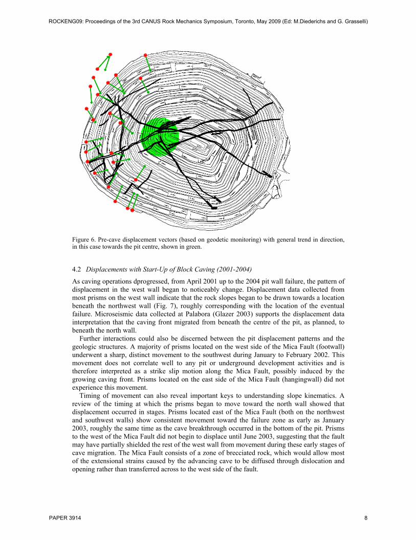
Figure 6. Pre-cave displacement vectors (based on geodetic monitoring) with general trend in direction, in this case towards the pit centre, shown in green.
4.2 Displacements with Start-Up of Block Caving (2001-2004)
As caving operations dprogressed, from April 2001 up to the 2004 pit wall failure, the pattern of displacement in the west wall began to noticeably change. Displacement data collected from most prisms on the west wall indicate that the rock slopes began to be drawn towards a location beneath the northwest wall (Fig. 7), roughly corresponding with the location of the eventual failure. Microseismic data collected at Palabora (Glazer 2003) supports the displacement data interpretation that the caving front migrated from beneath the centre of the pit, as planned, to beneath the north wall.
Further interactions could also be discerned between the pit displacement patterns and the geologic structures. A majority of prisms located on the west side of the Mica Fault (footwall) underwent a sharp, distinct movement to the southwest during January to February 2002. This movement does not correlate well to any pit or underground development activities and is therefore interpreted as a strike slip motion along the Mica Fault, possibly induced by the growing caving front. Prisms located on the east side of the Mica Fault (hangingwall) did not experience this movement.
Timing of movement can also reveal important keys to understanding slope kinematics. A review of the timing at which the prisms began to move toward the north wall showed that displacement occurred in stages. Prisms located east of the Mica Fault (both on the northwest and southwest walls) show consistent movement toward the failure zone as early as January 2003, roughly the same time as the cave breakthrough occurred in the bottom of the pit. Prisms to the west of the Mica Fault did not begin to displace until June 2003, suggesting that the fault may have partially shielded the rest of the west wall from movement during these early stages of cave migration. The Mica Fault consists of a zone of brecciated rock, which would allow most of the extensional strains caused by the advancing cave to be diffused through dislocation and opening rather than transferred across to the west side of the fault.
ROCKENG09: Proceedings of the 3rd CANUS Rock Mechanics Symposium, Toronto, May 2009 (Ed: M.Diederichs and G. Grasselli)
PAPER 3914 8
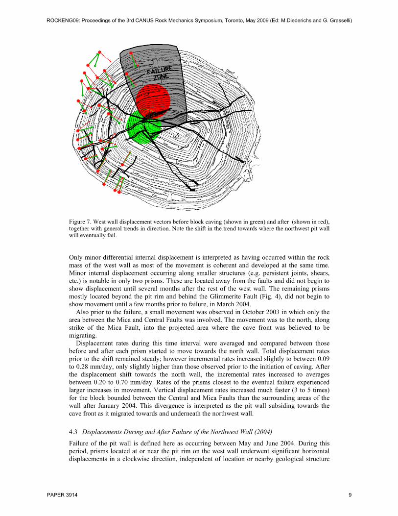
Figure 7. West wall displacement vectors before block caving (shown in green) and after (shown in red), together with general trends in direction. Note the shift in the trend towards where the northwest pit wall will eventually fail.
Only minor differential internal displacement is interpreted as having occurred within the rock mass of the west wall as most of the movement is coherent and developed at the same time. Minor internal displacement occurring along smaller structures (e.g. persistent joints, shears, etc.) is notable in only two prisms. These are located away from the faults and did not begin to show displacement until several months after the rest of the west wall. The remaining prisms mostly located beyond the pit rim and behind the Glimmerite Fault (Fig. 4), did not begin to show movement until a few months prior to failure, in March 2004.
Also prior to the failure, a small movement was observed in October 2003 in which only the area between the Mica and Central Faults was involved. The movement was to the north, along strike of the Mica Fault, into the projected area where the cave front was believed to be migrating.
Displacement rates during this time interval were averaged and compared between those before and after each prism started to move towards the north wall. Total displacement rates prior to the shift remained steady; however incremental rates increased slightly to between 0.09 to 0.28 mm/day, only slightly higher than those observed prior to the initiation of caving. After the displacement shift towards the north wall, the incremental rates increased to averages between 0.20 to 0.70 mm/day. Rates of the prisms closest to the eventual failure experienced larger increases in movement. Vertical displacement rates increased much faster (3 to 5 times) for the block bounded between the Central and Mica Faults than the surrounding areas of the wall after January 2004. This divergence is interpreted as the pit wall subsiding towards the cave front as it migrated towards and underneath the northwest wall.
4.3 Displacements During and After Failure of the Northwest Wall (2004)
Failure of the pit wall is defined here as occurring between May and June 2004. During this period, prisms located at or near the pit rim on the west wall underwent significant horizontal displacements in a clockwise direction, independent of location or nearby geological structure
ROCKENG09: Proceedings of the 3rd CANUS Rock Mechanics Symposium, Toronto, May 2009 (Ed: M.Diederichs and G. Grasselli)
PAPER 3914 9
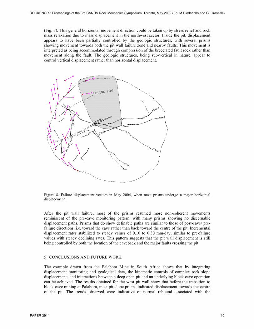
(Fig. 8). This general horizontal movement direction could be taken up by stress relief and rock mass relaxation due to mass displacement in the northwest sector. Inside the pit, displacement appears to have been partially controlled by the geologic structures, with several prisms showing movement towards both the pit wall failure zone and nearby faults. This movement is interpreted as being accommodated through compression of the brecciated fault rock rather than movement along the fault. The geologic structures, being sub-vertical in nature, appear to control vertical displacement rather than horizontal displacement.
Figure 8. Failure displacement vectors in May 2004, when most prisms undergo a major horizontal displacement.
After the pit wall failure, most of the prisms resumed more non-coherent movements reminiscent of the pre-cave monitoring pattern, with many prisms showing no discernable displacement paths. Prisms that do show definable paths are similar to those of post-cave/ pre-failure directions, i.e. toward the cave rather than back toward the centre of the pit. Incremental displacement rates stabilized to steady values of 0.10 to 0.30 mm/day, similar to pre-failure values with steady declining rates. This pattern suggests that the pit wall displacement is still being controlled by both the location of the caveback and the major faults crossing the pit.
5 CONCLUSIONS AND FUTURE WORK
The example drawn from the Palabora Mine in South Africa shows that by integrating displacement monitoring and geological data, the kinematic controls of complex rock slope displacements and interactions between a deep open pit and an underlying block cave operation can be achieved. The results obtained for the west pit wall show that before the transition to block cave mining at Palabora, most pit slope prisms indicated displacement towards the centre of the pit. The trends observed were indicative of normal rebound associated with the
ROCKENG09: Proceedings of the 3rd CANUS Rock Mechanics Symposium, Toronto, May 2009 (Ed: M.Diederichs and G. Grasselli)
PAPER 3914 10
excavation of the pit. However, once block caving began, movement of the west wall deviated towards the location of the eventual 2004 failure of the northwest wall.
At Palabora, review of the monitoring data and previous knowledge of the pit wall failure has led to several important observations that provide insight into the kinematics of the west wall. From these, the following working hypotheses were derived: a) the caving front acted as the dominant control for the pit slope movements observed, but the major fault zones crossing the pit also had a notable influence, b) the sub-vertical nature of the geologic structures tend to promote vertical movements, damp those that are horizontal and extensional, and have little to no affect on those that are horizontal and compressional, c) the Mica Fault shielded the West wall from induced strains during breakthrough of the cave and failure of the northwest wall, d) the location of the cave front along with the vertical nature of the geologic structures interacted to promote subsidence of the northwest wall with a feedback that promoted migration of the cave back towards the northwest wall, and e) the cave back does not appear to migrate up and along one of the major faults, but rather along the dominant joint set in the north wall.
As noted, these are only preliminary hypotheses based on observations, the integration of the monitoring and geology data sets. To further test these hypotheses, further 3-D distinct-element modelling is planned (to complement the completed work) as a means to provide support for or refute interpretations drawn from the pit slope monitoring data, as well as to explore possible future behaviour (e.g. Karami & Beddoes 2007). This work will also see the application of terrestrial laser scanning, photogrammetry and discrete fracture network (DFN) modeling, to develop higher resolution geological models to be evaluated for interactions related to the smaller-scale joint network. An ongoing collaboration with Rio Tinto, and the Resource Geotechnics Group at Simon Fraser University, as part of the Canadian Mine Caving and Subsidence Research initiative, will work towards the refinement of the geological model used in this analysis.
ACKNOWLEDGEMENTS
The authors would like to thank Michael Van Den Heever, Dawid Pretorius and the Palabora Mining Company, together with Allan Moss, Andre Van As and Rio Tinto Technical Services for providing access to the data used in this paper. The authors would also like to acknowledge Dr. Doug Stead of Simon Fraser University for his valuable input into this work. The authors would also like to thank Nick Rose and Piteau Associates Engineering Ltd for access to geotechnical reports as well as valuable commentary on the nature of the wall displacement. This work was funded through a Collaborative Research and Development grant from the Natural Sciences and Engineering Research Council of Canada (NSERC) in partnership with Rio Tinto.
REFERENCES
AMEC. 2005. Earth observation market development program land subsidence pre-commercial trial Palabora mine, South Africa. AMEC Report VM00344, 82 pp.
Board, M., Seldon, S., Brummer, R., & Pakalnis, R. 2000. Analysis of the failure of a large hangingwall wedge: Kidd Mine Division, Falconbridge, Ltd. CIM Bulletin 93(1043): 89-97.
Bond, J., Kim, D., Chrzanowski, A., & Szostak-Chrzanowski, A. Development of a fully automated, GPS based monitoring system for disaster prevention and emergency preparedness: PPMS+RT. Sensors 7: 1028-1046.
Brown, N., Kaloustian, S., & Roeckle, M. 2007. Monitoring of open pit mines using combined GNSS satellite receivesr and robotic total stations. In Potvin (ed.), Proc. 2007 Int. Symp. on Rock Slope Stability in Open Pit Mining and Civil Engineering, Perth. Perth: ACG, pp. 417-429.
Brummer, R., Li, H., & Moss, A. 2006. The transition from open pit to underground mining: An unusual slope failure mechanism at Palabora. In Stability of Rock Slopes in Open Pit Mining and Civil Engi-neering Situations. Johannesburg: SAIMM, Symposium Series S44, pp. 411-420.
ROCKENG09: Proceedings of the 3rd CANUS Rock Mechanics Symposium, Toronto, May 2009 (Ed: M.Diederichs and G. Grasselli)
PAPER 3914 11
Day, A.P. & Seery, J.M. 2007. Monitoring of a large wall failure at Tom Price Iron Ore Mine. In Potvin (ed.), Proc. 2007 Int. Symp. on Rock Slope Stability in Open Pit Mining and Civil Engineering, Perth. Perth: ACG, pp. 333-340.
Dunnicliff, J. 1988. Geotechnical instrumentation for monitoring field performance. New York: Kohn Wiley & Sons.
Eberhardt, E., Watson, A.D., & Loew, S. 2008. Improving the interpretation of slope monitoring and early warning data through better understanding of complex deep-seated landslide failure mecha-nisms. In Chen et al. (eds.), Landslides and Engineered Slopes: From the Past to the Future, Pro-ceedings of the 10th International Symposium on Landslides and Engineered Slopes, Xi’an. London: Taylor & Francis, vol. 1, pp. 39-51.
Fukuzono, T. 1985. A new method for predicting the failure time of a slope. In Proc. IVth Int. Conf. and Field Workshop on Landslides, Tokyo. Tokyo: NRCDP, pp. 145-150.
Glazer, S. 2003. Seismology,:A tool for cave monitoring. Rio Tinto Internal Presentation. Harries, N.J. & Roberts, H. 2007. The use of Slope Stability Radar (SSR) in managing slope instability
hazards. In Eberhardt et al. (eds.), Proc. 1st Canada-U.S. Rock Mechanics Symposium, Vancouver. London: Taylor & Francis, v1, pp. 53-59.
Harries, N., Noon, D. & Rowley, K. 2006. Case studies of slope stability radar used in open cut mines. In Stability of Rock Slopes in Open Pit Mining and Civil Engineering Situations. Johannesburg: SAIMM, Symposium Series S44, pp. 335-342.
Hebblewhite, B.K. 2003. Northparkes findings – The implications for geotechnical professionals in the mining industry. In 1st Australasian Ground Control in Mining Conference. Sydney: UNSW Press, pp. 3-10.
Itasca Consulting Group Inc. 1999. UDEC (Universal Distinct Element Code), Version 3.1. Minneapolis: ICG.
Itasca Consulting Group Inc. 2003. 3DEC (3-Dimensional Distinct Element Code), Version 3.0. Minneapolis: Minnesota.
Jarosz, A. & Wanke. D. 2003. Use of InSAR for monitoring of mining deformations. Proc. of Fringe, 2003 Workshop, Frascati, Italy, pp. 1-5.
Karami, A. & Beddoes, R. 2007. Numerical assessment of step-path failure of northwest wall of A154 pit, Diavik Diamond Mine. In Potvin (ed.), Proc. 2007 Int. Symp. on Rock Slope Stability in Open Pit Mining and Civil Engineering, Perth. Perth: ACG, pp. 333-340.
Little, M.J. 2006. Slope monitoring strategy at PPRust open pit operation. In Stability of Rock Slopes in Open Pit Mining and Civil Engineering Situations. Johannesburg: SAIMM, Symposium Series S44, pp. 211-230.
Logan, A. S., Villaescusa, E., Stampton V. R., Struthers, M. A. and Bloss, M. l. 1993. Geotechnical instrumentation and ground behaviour monitoring at Mount Isa, In Geotechnical instrumentation and monitoring in open pit and underground mining, Szwedzicki, T. (ed.), A. A. Balkema, Rotterdam, Netherlands, pp. 321- 329.
Loubser, P. 1993. Detection of abandoned mine workings at KCGM’s Open Pit Operations, In Geotechnical instrumentation and monitoring in open pit and underground mining. Szwedzicki, T. (ed.), A. A. Balkema, Rotterdam, Netherlands, pp. 331-338.
Moore, D.P. Imrie, A.S. & Baker D.G. 1991. Rockslide risk reduction using monitoring. In Proc., Canadian Dam Association Meeting, Whistler, BC. Canadian Dam Safety Association.
Moss, A., Diachenko, Townsend, P. 2006. Interation between the block cave and the pit slopes at Palabora Mine. In Stability of Rock Slopes in Open Pit Mining and Civil Engineering Situations. Johannesburg: SAIMM, Symposium Series S44, pp. 399–410.
Piteau Associates Engineering Ltd. 2005. Assessment of Pit Wall Stability and Slope Displacement as a Result of Interaction Between the Open Pit and Underground Mine. Internal Report.
Rose, N.D. & Hungr, O. 2007. Forecasting potential rock slope failure in open pit mines using the inverse-velocity method. Int. J. Rock Mech. Min. Sci. 44(2): 308-320.
Walker, P., Knight, P., Johnson, T., & Speight, H. 2006. Pushback 8 South – A case study in pit slope management In Stability of Rock Slopes in Open Pit Mining and Civil Engineering Situations. Johannesburg: SAIMM, Symposium Series S44, pp. 435–450.
Willenberg, H., Evans, K. Eberhardt, E. Spillmann, T., & Loew, S. 2008. Internal structure and deformation of an unstable crystalline rock mass above Randa (Switzerland): Part II – Three dimension deformational patterns, Engineering Geology.
ROCKENG09: Proceedings of the 3rd CANUS Rock Mechanics Symposium, Toronto, May 2009 (Ed: M.Diederichs and G. Grasselli)
PAPER 3914 12