importance of rts clocks - national university of ireland...
TRANSCRIPT

1
Clock Synchronisation for RTS
Dr. Hugh Melvin, Dept. of IT, NUI,G 1
Importance of RTS Clocks• RealTime implies need for accurate timekeeping• Precise Time & Timing
– Two distinct issues– Both often required for RTS
• Time (of day)
Dr. Hugh Melvin, Dept. of IT, NUI,G 2
– UTC (Universal Coordinated Time)– Chronological event recording– Crucial for fault diagnosis in distributed systems
• Timing– Frequency is key issue– Crucial in synchronising components
Time & Timing• Time
– UTC evolved from Greenwich Mean Time GMTTime Synchronisation
Dr. Hugh Melvin, Dept. of IT, NUI,G 3
– Time Synchronisation• How closely 2 clocks
agree on Time of Day
• Timing• How closely 2 entities
operate at same frequency

2
Greenwich• Home of Time & the
Prime Meridian• Longitude 0 & GMT
agreed in 1884– GMT driven by
expansion of railways
Dr. Hugh Melvin, Dept. of IT, NUI,G 4
p yand need for national/international consistency
• “Timeball” rises and falls at 13.00 hrs– Then site of London
docks– In service since 1833
Greenwich
Dr. Hugh Melvin, Dept. of IT, NUI,G 5
18th Century GPS
• 18th century maritime navigation– Latitude
• Astronomical
Dr. Hugh Melvin, Dept. of IT, NUI,G 6
– Longitude dilemma
• Solutions– Astronomical
– Time based• Need for robust maritime clock

3
18th Century GPS• Time based location
– Set ship clock before setting sail from time ball
– Compare with 'local time' to give one's position east or west of the home port.
Dr. Hugh Melvin, Dept. of IT, NUI,G 7
• 360° = 24 hr 15 ° = 1 hr
– Problem was getting clock to work well on a ship
– Lincolnshire carpenter, John Harrison
• H4 won him the great Longitude Prize of £20,000. .. in 1759
Time & Timing Examples• Time
• Distributed Control Systems : Moneypoint– Facilitates fault diagnosis
• Power Line Fault Detection• VoIP delay monitoring• SLA adherence monitoring• Billing systems
Dr. Hugh Melvin, Dept. of IT, NUI,G 8
g y• Database/File Integrity timestamps
• Timing• Synchronising redundant devices 2v3,2v4 voters etc• TDM within GSM/POTS
– Avoids bit errors• MM applications : skew issues due to ‘timing’ mismatch
– Delay/Buffer problems
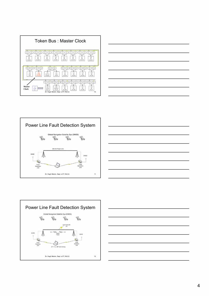
Power System Control• AS station
– Time: Token Bus Synchronisation via Master Clock• Critical for chronological data logging / fault diagnosis• Approx 1 msec level synch reqd• Provided via GPS• Generator Earth Fault / Overcurrent ..
– Which came first .. msec level data required
Ti i S h i i 2 3 t t
Dr. Hugh Melvin, Dept. of IT, NUI,G 9
– Timing: Synchronising 2v3 voter systems• Need to deliver verdicts simultaneously
• Power Line Fault Monitoring• Noise burst travels in both directions• Speed of light c = 3* 108 m/s 0.3 m / nanosec
» synch level of usec needed (300 m)
• Synchroscope– Frequency alignment
4
Token Bus : Master Clock
U/IA U/IB U/IA U/IB U/IA U/IB U/IA U/IB U/IA U/IBU/IA U/IB U/IA U/IBU/IA U/IB
101N8
AS220E
102N8
AS220E
103N8
AS220E
104N8
AS220E
105N8
AS220E
106N8
AS220E
107N8
AS220E
108N8
AS220E
Dr. Hugh Melvin, Dept. of IT, NUI,G 10
U/IA U/IB U/IA U/IB U/IA U/IB U/IA U/IB U/IA U/IBU/IA U/IB
126N-BKBus 0
123N-UHRM-Clock
121N16
OS254
112N8
AS220E
111N8
AS220E
110N8
AS220E
109N8
AS220E
U/IA U/IB U/IA U/IB U/IA U/IB U/IA U/IBU/IA U/IB U/IA U/IB
160NS5NAT
PG750
133N8
AS EHF
132N8
AS EHF
131N8
AS EHF
128N8
AS231
125N16R30
141NAT-24Synogate
U/IA U/IB
127N-BK Bus 1
MasterClock
Power Line Fault Detection System
Dr. Hugh Melvin, Dept. of IT, NUI,G 11
Power Line Fault Detection System
Dr. Hugh Melvin, Dept. of IT, NUI,G 12

5
Timing : 2v3 Redundancy
CPU 2CPU 1 CPU 3
N8 N8
U/I U/I
Bus ABus B
CS275
Dr. Hugh Melvin, Dept. of IT, NUI,G 13
.. .. ........
2 out of 3
Non-Redundant Control Circuits
Double RedundantSafety Circuits Triple Redundant Safety Circuits
Timing: Synchroscope
• Frequency alignment between generator and transmission grid
• No room for
Dr. Hugh Melvin, Dept. of IT, NUI,G 14
significant error
Synchroscope
Dr. Hugh Melvin, Dept. of IT, NUI,G 15

6
Telecommunications• Precise timing synch fundamental to current
systems– POTS
• SDH/SONET
– Cellular Networks• GSM/CDMA
Dr. Hugh Melvin, Dept. of IT, NUI,G 16
– Loss of synch• Bit errors (slip) data loss• System failure
• IP-based NGN – Circuit Packet switched network
• Loss of core synch key challenge• http://forum.telecom-sync.com/
Dr. Hugh Melvin, Dept. of IT, NUI,G 17
Dr. Hugh Melvin, Dept. of IT, NUI,G 18

7
Dr. Hugh Melvin, Dept. of IT, NUI,G 19
Soft RTS
• POTS operation based on TDM• PCME1E2..E4 SDH/SONET• Precise timing synchronisation reqd throughout
the network for correct system operation
• GSM : FDM + TDM
Dr. Hugh Melvin, Dept. of IT, NUI,G 20
• Each FDM channel divided out to 8 users via TDM
Soft RTS
• IP Multimedia Applications– Time
• Delay / Jitter measurement imp in packet (IP) networks
• More advanced QoS possible through synchronised timeRecall G 1010
Dr. Hugh Melvin, Dept. of IT, NUI,G 21
– Recall G.1010
– Basis of SLA delay/jitter measurement important
– Timing• Skew Issues between various clocks
– Time & Timing• Lip Synch challenge
• MMOG

8
Dr. Hugh Melvin, Dept. of IT, NUI,G 22
Dr. Hugh Melvin, Dept. of IT, NUI,G 23
Audio-System Clock Skew
Dr. Hugh Melvin, Dept. of IT, NUI,G 24

9
Timing ‘Skew’ for IP Multimedia
Dr. Hugh Melvin, Dept. of IT, NUI,G 25
Lip Synch ETSI STQ
-0,5
0
Diff
gra
de
) B
C C'
B'
Undetectability plateau
Detectability threshold
Dr. Hugh Melvin, Dept. of IT, NUI,G 26
0 20 40 60 80 100-20-40-60-80-100-120-140-160-180-200
-2
-1,5
-1
Su
bje
ctiv
e e
valu
atio
n r
esu
lts (
D
Delay time (ms)
A A'
Sound delay wrtvision
Sound advanced wrtvision
Acceptability threshold
Synch Time for MMOG
Dr. Hugh Melvin, Dept. of IT, NUI,G 27

10
Computer Clocks• Most commonly consist of quartz crystal and
a counter• Crystal oscillates at defined rate (Hz) which
generates a consistent tick and increments a software counter C t l t l t d t ti t d d
Dr. Hugh Melvin, Dept. of IT, NUI,G 28
• Counter value translated to time standard– UTC (Univ. Coord. Time) .. Based on GMT
• Primary Source: Atomic Clocks – TAI (International Atomic Time)
» But requires leap seconds every few years!» UTC = TAI + Leap_Seconds
• Crystal Quality described by accuracy & stability
Computer Clocks
• Accuracy relates to how close the crystal freq is to its rated value– Determined largely by manufacturing process
• Get what you pay for!
• Stability relates to how frequency variesf
Dr. Hugh Melvin, Dept. of IT, NUI,G 29
– Influenced by parameters such as:• Temperature .. Eg. 2ppm /C• Ageing
– Eg. Cesium Beam: 3 x 10-12 / year
• Noise
• Note: Frequency i.e. timing errors lead to time(of day) errors
Computer Clocks• Improved Quality Timekeeping ?
– Option A: Stick with crystals• Precision manufacturing costly• Temperature Compensated Crystal Osc.(TCXO)• Oven Controlled Crystal Osc.(OCXO)
– Option B :
Dr. Hugh Melvin, Dept. of IT, NUI,G 30
– Option B : • Buy an Atomic Clock • .. or GPS Receiver (based on atomic clock) • .. or Radio Receiver DCF77, MSF .. LFR signal .. less accurate• GPS most popular approach to providing accurate/stable time
– Option C : Cheaper Approach• Software based approach to discipline cheap crystal clocks• Crude but useful for certain applications
11
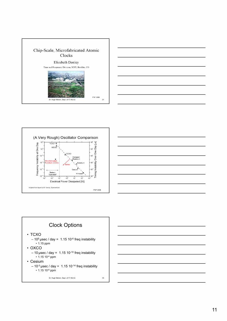
Dr. Hugh Melvin, Dept. of IT, NUI,G 31
Dr. Hugh Melvin, Dept. of IT, NUI,G 32
Clock Options
• TCXO– 105 µsec / day = 1.15 10-6 freq instability
• 1.15 ppm
• OXCO
Dr. Hugh Melvin, Dept. of IT, NUI,G 33
– 10 µsec / day = 1.15 10-10 freq instability• 1.15 10-4 ppm
• Cesium– 10-3 µsec / day = 1.15 10-14 freq instability
• 1.15 10-8 ppm

12
Clock Terminology
• Some confusion with terms in literature– Paxson/Mills terminology used here– Offset
• Difference between time reported by clock C, C(t) and true clock (UTC) at true time t.
• Also relative offset between clocks C and C
Dr. Hugh Melvin, Dept. of IT, NUI,G 34
• Also relative offset between clocks C1and C2
– C1(t) - C2(t)
– Skew• Difference in frequency between clock C and a true clock
(UTC) , C’(t)• Defined in ppm (usec per sec)• +/-12 ppm approx = +/- 1 sec/day• Also relative skew between clocks C1and C2
– C1’(t) - C2
’(t)
Dr. Hugh Melvin, Dept. of IT, NUI,G 35
Clock Terminology• Skew
– A large skew rate rapidly increasing offset frequent resynchronisation
– If specify max abs skew rate for clock C of
))(1()()())(1(121212tttCtCtt
Dr. Hugh Melvin, Dept. of IT, NUI,G 36
– Clock should operate within cone of acceptability
• Drift– Rate of change of frequency C’’(t)
• Eg. Ageing influence or change in temperature
– Not usually significant except over long timescales– Note linear relationship in previous slide
• No drift evident

13
Cone of Acceptability
Clock
Slope = 1 = True Clock
Sl 1
Slope = 1 +
Dr. Hugh Melvin, Dept. of IT, NUI,G 37
Real Time
Time Slope = 1 -
Q: How are accuracy and stability related to cone of acceptability?
Clock Synchronisation• Perfect clocks do not exist
• Eg. PC System Clock NTP Server GPS Receiver GPS Atomic Clock GPS Master Atomic Clock ??
• Examine two separate scenarios
Dr. Hugh Melvin, Dept. of IT, NUI,G 38
Examine two separate scenarios• Localised Cluster of Clocks
– Eg. Power System Control / Fly-by-wire Systems
– Also widely distributed clocks over deterministic network
» Propagation time known (can be compensated for)
• Distributed clocks over non-deterministic network– More difficult scenario
– Eg. Internet Clock Synchronisation via NTP
Localised Cluster of Clocks• Hardware-based Phase Locked Loops (PLL)
– Oscillator output is aligned to the input signal.– Input signal can come from a
• Master Clock • Combination of outputs from all other clocks
– Input signal used to drive its PLL
Dr. Hugh Melvin, Dept. of IT, NUI,G 39
Input signal used to drive its PLL– Can also compensate for Propagation Delay variations– Expensive but precise approach
• Resolve timing errors accurate time
• Similar approach used in widely distributed scenario– GPS / POTS / GSM all use variants of this approach
• But only for timing synchronisation .. Not really concerned with time

14
PLL
VCOComparatorInput Signal
Dr. Hugh Melvin, Dept. of IT, NUI,G 40
Signal
VCO = Voltage Controlled Oscillator
Freq controlled by applied input voltage
Distributed Clocks
• More difficult environment if underlying network non deterministic
• Expense of hardware based approach cannot be justified for many Soft-Firm RTS
Dr. Hugh Melvin, Dept. of IT, NUI,G 41
• Cheap software based approach– Network Time Protocol (NTP) (www.ntp.org)
– RFC 1305 (www.ietf.org) • Unix-based NTP daemon now ported to most OS
NTP Clock Synchronisation• More concerned with time rather than timing• Some general principles
– Fault Tolerance critical• Identify and isolate faulty clocks• Note: A faulty clock is one that does not operate within
cone of acceptability
Dr. Hugh Melvin, Dept. of IT, NUI,G 42
cone of acceptability– Cf Clock Quality: May be stable but inaccurate
– Avoid setting clocks backward– Event processing nightmare– OS problems eg. Timers / timeslicing
– Avoid large step changes• Amortize the required change (+/-) over a series of short
intervals (eg. over multiple ticks)
15
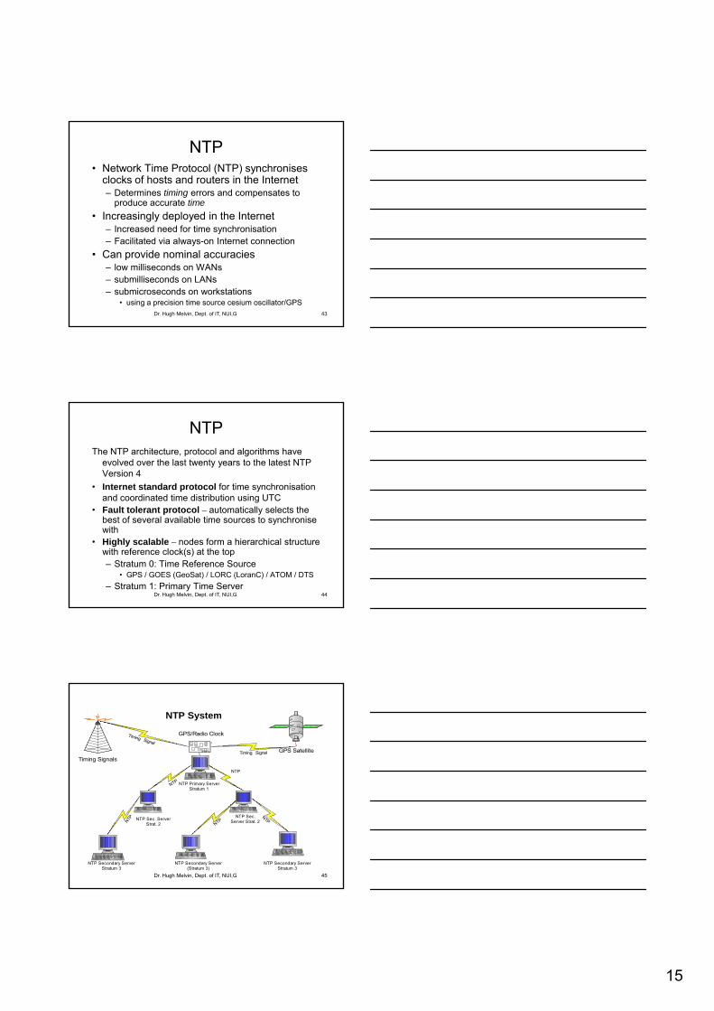
NTP• Network Time Protocol (NTP) synchronises
clocks of hosts and routers in the Internet– Determines timing errors and compensates to
produce accurate time
• Increasingly deployed in the Internet
Dr. Hugh Melvin, Dept. of IT, NUI,G 43
– Increased need for time synchronisation– Facilitated via always-on Internet connection
• Can provide nominal accuracies – low milliseconds on WANs– submilliseconds on LANs– submicroseconds on workstations
• using a precision time source cesium oscillator/GPS
NTPThe NTP architecture, protocol and algorithms have
evolved over the last twenty years to the latest NTP Version 4
• Internet standard protocol for time synchronisation and coordinated time distribution using UTC
Dr. Hugh Melvin, Dept. of IT, NUI,G 44
• Fault tolerant protocol – automatically selects the best of several available time sources to synchronise with
• Highly scalable – nodes form a hierarchical structure with reference clock(s) at the top– Stratum 0: Time Reference Source
• GPS / GOES (GeoSat) / LORC (LoranC) / ATOM / DTS
– Stratum 1: Primary Time Server
NTP
Timing Signal
Timing Signal
Timing Signals
GPS Satellite
GPS/Radio Clock
NTP Primary Server
NTP System
NTP
Dr. Hugh Melvin, Dept. of IT, NUI,G 45
NTPNTPN
TP
N
NTP Secondary ServerStratum 3
NTP Secondary Server(Stratum 3)
NTP Secondary ServerStratum 3
NTP Sec. ServerStrat. 2
NTP Sec.Server Strat. 2
yStratum 1

16
NTP OperationPeer 1
Peer 2
Filter 1
Peer 3
Filter 2
Filter 3
Intersectionand
ClusteringAlgorithms
CombiningAlgorithm
Loop Filter
VFO
P/F-Lock Loop
Dr. Hugh Melvin, Dept. of IT, NUI,G 46
• Complex Software comprising various algorithms• Filtering Alg.• Clustering and Intersection Alg.• Combining Alg.• Clock Discipline
NTP Messages VFO
NTP Operation
• NTP Algorithms act upon a set of variables– Offset / Delay / Dispersion– Dispersion
11
0
in
iijj w
Dr. Hugh Melvin, Dept. of IT, NUI,G 47
• w = 0.75• These are relative to both peer and root
Offset θ ΘDelay δ ΔDispersion ε Ε
jiij
Client Server Mode
• UDP/IP packets for data transfer– Several packet exchanges between client/server– Client
• originate timestamp A within packet being sent.
– Server receives such a packet:
Dr. Hugh Melvin, Dept. of IT, NUI,G 48
p• receive timestamp B• transmit timestamp C
– Client• Processes A,B,C as well as final packet arrival D• Determine offset and Round Trip Delay (RTD) • Note: RTD != RTT

17
NTP Operation
C 3.59.022B 3.59.020
15 ms 15 ms
Dr. Hugh Melvin, Dept. of IT, NUI,G 49
D 3.59.032A 3.59.000
15 ms 15 ms
Symmetric Network : 15 ms each way (actual delay)
RTD = (D - A) – (C – B) = 32 – 2 = 30 msec (RTT =?)
Offset = ½[(B-A) - (D-C)] = (20 – 10)/2 = 5 ms
Filtering Algorithm
Dr. Hugh Melvin, Dept. of IT, NUI,G 50
• Filtering algorithm looks at last 8 samples
•Chooses sample with min RTD
• Reduces offset errors by a factor of about ten
• Effective at removing spikes
Intersection Algorithm
Clocks 1, 2 ,3 are truechimers4 is a falseticker3
2
1
4
X1
X2
Dr. Hugh Melvin, Dept. of IT, NUI,G 51
• Selects a subset of peers
• Based on intersection of confidence intervals
• Identifies truechimers & falsetickers
• eg. From 1,2,3,4 above

18
Intersection Algorithm
• Estimated offset to each clock is mid pt • But: Any point in each confidence interval may
represent actual time as seen by that peer
• If clocks 14 are correct, there must exist a common intersection
Cl k 4 t lik l i t di d
Dr. Hugh Melvin, Dept. of IT, NUI,G 52
Clock 4 most likely incorrect.. disregard
• Interval X1 = smallest intersection containing points from 1,2,3• But also include the max no of interval midpoints
– Select X2 interval
– Could select mid pt of X2 .. or refine further
Clustering (Clock Selection)
• Sort surviving clocks by stratum and incr synch distance (RTD/2 + disp), S1 S2 S3
• Remove outliers that have significant dispersion relative to other survisors– Compute Select Dispersion of each clock
Dr. Hugh Melvin, Dept. of IT, NUI,G 53
• Weighted sum of differences to other clocks
– Compute Sample Dispersion of each clock• Weighted sum of diff relative to past samples of same
clocks
– If Max SelDisp > Min SamDisp• Remove this survivor and repeat• Favours candidates at start of sorted list
Favours lowest stratum / delay
Clustering algorithm
For each survivor si, compute the select dispersion (weighted sum of clock difference) between si and all others.
Let smax be the survivor with max select dispersion (relative to all other survivors) and smin the survivor with min sample dispersion
Sort survivors of intersection algorithm by increasing synchronization distance(RTD/2 + dispersion). Let n = no of
survivors and nmin a lower limit (eg.3).
Dr. Hugh Melvin, Dept. of IT, NUI,G 54
no
yes
) min p p(clock differences relative to past samples of the same survivor).
smax smin or n nmin
Delete the survivor smax; reduce n by one
The resulting survivors are processed by the combining algorithm to produce a weighted average used as the final offset adjustment

19
Combining Algorithm• Combine result from survivors of
selection algorithm
• Weighted offset determined based on– Offset of survivors Θ
Dr. Hugh Melvin, Dept. of IT, NUI,G 55
– Synchronisation distance Λ
– Eg. 2 survivors (S1,S2) with parameters
– Final Offset =),(),,( 2211
)/()..( 211221
Combining Algorithm Example
• S1,S2 where S1 = (2 ms, 30) and S2 = (3 ms, 10)
Fi l Adj t t
)/()..( 211221
Dr. Hugh Melvin, Dept. of IT, NUI,G 56
• Final Adjustment =– (2(10) + 3(30)) / (30 + 10)
= 110 / 40 = 2.75 msec
• Implemented via the Clock Discipline
Clock Discipline
• Recall– No time reversal!
– Avoid step changes
• Hybrid phase/frequency lock (PLL/FLL)
Dr. Hugh Melvin, Dept. of IT, NUI,G 57
• Hybrid phase/frequency-lock (PLL/FLL) feedback loop
• PLL/FLL Mode: Depends on polling interval

20
PLL and FLL weight factors
Dr. Hugh Melvin, Dept. of IT, NUI,G 58
• Weight factors (not to scale)
• PLL predict (red) most important at shorter poll intervals to 24 s
• FLL predict (blue) most important at longer poll intervals to 217 s
Clock Models
• Unix Clock Model• settimeofday( ), adjtime( )
• Kernel variables tick , tickadj
• adjtime adjusts clock every tick
Dr. Hugh Melvin, Dept. of IT, NUI,G 59
– Can amortise reqd change gradually by making adjustment every tick eg. every 10 msec
– Note: Newer Unix/Linux kernels 1000Hz 1msec
• 3 clock rates– Normal rate .. Add 10 msec every tick (100 Hz)
– Normal Rate +/- tickadj
– Eg. If tickadj = 5us Normal Rate +/- 500 ppm
Simplified NTP Operation • NTP adjusts every sec via adjtime
– Eg. If clock skew is +100 ppm & tickadj=5us– NTP will operate to keep clock effectively running at correct
rate
» Normal Rate - 500 ppm over 0.2 sec
» Normal Rate for 0.8 sec
Dr. Hugh Melvin, Dept. of IT, NUI,G 60
» Effective skew = 0 ppm
– Results in sawtooth – pattern
• Newer Unix Kernels have advanced NTP features– ntp_adjtime( ), ntp_gettime()
– Eliminates the sawtooth pattern
• NTP maintains accurate time by resolving and compensating for timing errors

21
NTP Implementation
• Install NTP • Set up ntp.conf file
– List of servers that you wish to connect to– Need to consider
• Redundancy, Path Diversity, Low RTD
Dr. Hugh Melvin, Dept. of IT, NUI,G 61
y, y,
• Start up NTP daemon ntpd• File ntp.drift records clock skew
– Unfortunate file name .. Adds to confusion !• Other utilities
– ntpq, ntpdate– See www.ntp.org
Dr. Hugh Melvin, Dept. of IT, NUI,G 62
Refid:
DCF: 77.5 KHz Radio Signal
PTB: German time signal
Dr. Hugh Melvin, Dept. of IT, NUI,G 63

22
Time difference
Dr. Hugh Melvin, Dept. of IT, NUI,G 64
Server Details
• when: no of sec since last response
• poll : interval between queries
• reach : Reachability in octal– 11111111 = 3778 = max
Dr. Hugh Melvin, Dept. of IT, NUI,G 65
– 11101110 = 3568 last + 5th probe lost
• Symbol to LHS of server– * : Synch Source – survivor with smallest dispersion
– + :other candidates included in final combination alg
– - : Discarded by clustering alg
– x : Falseticker acc to intersection alg
Dr. Hugh Melvin, Dept. of IT, NUI,G 66

23
NTP Robustness Issues
• Redundancy
• Path Diversity
• Symmetric Networks
Dr. Hugh Melvin, Dept. of IT, NUI,G 67
y
• Proximity to Primary Reference Sources– See results
• OS & Network Load– Platform Dependencies
NTP Operation : Asymmetry
C 3.59.017B 3.59.015
10 ms 20 ms
Dr. Hugh Melvin, Dept. of IT, NUI,G 68
D 3.59.032A 3.59.000
10 ms 20 ms
Offset still 5 ms but Asymmetric Network
RTD = (D - A) – (C – B) = 32 – 2 = 30 msec
Offset = ½[(B-A) - (D-C)] = (15 – 15)/2 = 0 ms .. Error
NTP Operation : Asymmetry
C 3.59.017B 3.59.015
15 ms 15 ms
Dr. Hugh Melvin, Dept. of IT, NUI,G 69
D 3.59.032A 3.59.000
15 ms 15 ms
NTP’s Symmetric view of Asymmetric Network
RTD = (D - A) – (C – B) = 32 – 2 = 30 msec
Offset = ½[(B-A) - (D-C)] = (15 – 15)/2 = 0 ms !
Exercise: What is the maximum error in this calculation?
24
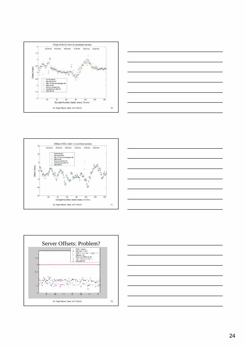
Dr. Hugh Melvin, Dept. of IT, NUI,G 70
Dr. Hugh Melvin, Dept. of IT, NUI,G 71
Server Offsets: Problem?
Dr. Hugh Melvin, Dept. of IT, NUI,G 72

25
NTP at NUI Galway• Public NTP servers
– ntp-galway.hea.net since 2002
– 2009
• 25,000 different clients
• 62,000 requests per hour
• Symmetricom S300 Server
– GPS
– DCF 77
– Oven Crystal
– Secondary server ntp2.it.nuigalway.ie
• Trimble GPS
• Linux based PC
Dr. Hugh Melvin, Dept. of IT, NUI,G 73
Dr. Hugh Melvin, Dept. of IT, NUI,G 74
Dr. Hugh Melvin, Dept. of IT, NUI,G 75

26
ntp-galway.hea.net
• GPS receiver
• DCF 77 Radio
• Also peers with– Computer Services
– ntp2.it.nuigalway.ie
– Dublin, UK, mainland europeanservers
Dr. Hugh Melvin, Dept. of IT, NUI,G 76