implementing l3 at the data center access layer on … ospf route summarization to ... ecmp...
TRANSCRIPT
IMPLEMENTATION GUIDE
Copyright © 2010, Juniper Networks, Inc. 1
IMPLEMENTING L3 AT THE DATA CENTER ACCESS LAYER ON JUNIPER NETWORKS INFRASTRUCTURE
Although Juniper Networks has attempted to provide accurate information in this guide, Juniper Networks does not warrant or guarantee the accuracy of the information provided herein. Third party product descriptions and related technical details provided in this document are for information purposes only and such products are not supported by Juniper Networks. All information provided in this guide is provided “as is”, with all faults, and without warranty of any kind, either expressed or implied or statutory. Juniper Networks and its suppliers hereby disclaim all warranties related to this guide and the information contained herein, whether expressed or implied of statutory including, without limitation, those of merchantability, fitness for a particular purpose and noninfringement, or arising from a course of dealing, usage, or trade practice.
2 Copyright © 2010, Juniper Networks, Inc.
IMPLEMENTATION GUIDE - Implementing L3 at the Data Center Access Layer on Juniper Networks Infrastructure
Table of Contents
Introduction . . . . . . . . . . . . . . . . . . . . . . . . . . . . . . . . . . . . . . . . . . . . . . . . . . . . . . . . . . . . . . . . . . . . . . . . . . . . . . . . . . . . . . . . . . . . . . . . . . . . . . . . . . . . . . . . 4
Scope . . . . . . . . . . . . . . . . . . . . . . . . . . . . . . . . . . . . . . . . . . . . . . . . . . . . . . . . . . . . . . . . . . . . . . . . . . . . . . . . . . . . . . . . . . . . . . . . . . . . . . . . . . . . . . . . . . . . . . 5
Target Audience . . . . . . . . . . . . . . . . . . . . . . . . . . . . . . . . . . . . . . . . . . . . . . . . . . . . . . . . . . . . . . . . . . . . . . . . . . . . . . . . . . . . . . . . . . . . . . . . . . . . . . . . . . 5
Design Considerations . . . . . . . . . . . . . . . . . . . . . . . . . . . . . . . . . . . . . . . . . . . . . . . . . . . . . . . . . . . . . . . . . . . . . . . . . . . . . . . . . . . . . . . . . . . . . . . . . . . . . . 6
Implementation and Configuration Guidelines . . . . . . . . . . . . . . . . . . . . . . . . . . . . . . . . . . . . . . . . . . . . . . . . . . . . . . . . . . . . . . . . . . . . . . . . . . . . . . 8
Connecting the Access Layer to the Core Layer over L3 . . . . . . . . . . . . . . . . . . . . . . . . . . . . . . . . . . . . . . . . . . . . . . . . . . . . . . . . . . . . . . . . . . . 8
Connect the Access Layer to the Core Layer via 10 Gbps Uplink . . . . . . . . . . . . . . . . . . . . . . . . . . . . . . . . . . . . . . . . . . . . . . . . . . . . . . . . . 9
Configure the Routed VLAN Interface on the Access Layer EX4200 as the Default
Gateway for Servers . . . . . . . . . . . . . . . . . . . . . . . . . . . . . . . . . . . . . . . . . . . . . . . . . . . . . . . . . . . . . . . . . . . . . . . . . . . . . . . . . . . . . . . . . . . . . . . . . . 10
Enable LAG using Physical Links from Different Virtual Chassis Members (Uplink or NIC Teaming) . . . . . . . . . . . . . . . . . . . . 10
Configure an L3 Sub-Interface for Cross-Connect Uplink LAGs Between Access and Core Tiers . . . . . . . . . . . . . . . . . . . . . . . . 12
Set Up a Virtual Router for a Function Area and Configure OSPF Areas . . . . . . . . . . . . . . . . . . . . . . . . . . . . . . . . . . . . . . . . . . . . . . . . 12
Configure BFD to Achieve Fast Failover in OSPF Adjacencies between EX Series and MX Series Devices . . . . . . . . . . . . . . . 13
Configure GRES and Protocol Graceful Restart to Increase Network Stability in Case of a RE Failure . . . . . . . . . . . . . . . . . . . 13
Configuring EX4500 Access Switch . . . . . . . . . . . . . . . . . . . . . . . . . . . . . . . . . . . . . . . . . . . . . . . . . . . . . . . . . . . . . . . . . . . . . . . . . . . . . . . . . . . 14
Connecting the Core to the Access Layer over L3 . . . . . . . . . . . . . . . . . . . . . . . . . . . . . . . . . . . . . . . . . . . . . . . . . . . . . . . . . . . . . . . . . . . . . . . . 14
Enable LAG on the MX Series Router for Connecting to Access Layer Switches. . . . . . . . . . . . . . . . . . . . . . . . . . . . . . . . . . . . . . . . . 14
Configure an L3 Sub-Interface for Cross-Connect Uplinks between Access and Core Tiers . . . . . . . . . . . . . . . . . . . . . . . . . . . . . 15
Configure OSPF Adjacencies Within a Virtual Router on Core MX Series Routers . . . . . . . . . . . . . . . . . . . . . . . . . . . . . . . . . . . . . . . 15
Configure GRES and NSR to Increase Network Stability in Case of an RE Failure . . . . . . . . . . . . . . . . . . . . . . . . . . . . . . . . . . . . . . . 16
Configuring L3 on the Core MX Series Routers . . . . . . . . . . . . . . . . . . . . . . . . . . . . . . . . . . . . . . . . . . . . . . . . . . . . . . . . . . . . . . . . . . . . . . . . . . . 16
Configure Areas and Allocate Metrics to Optimize OSPF Database on MX Series for Scalability . . . . . . . . . . . . . . . . . . . . . . . . 16
Configure OSPF Route Summarization to Optimize OSPF Database . . . . . . . . . . . . . . . . . . . . . . . . . . . . . . . . . . . . . . . . . . . . . . . . . . . 18
ECMP Per-Packet Load Balancing Consideration for Enabling Active/Active MX Series Routers . . . . . . . . . . . . . . . . . . . . . . . . 18
Failover Scenarios . . . . . . . . . . . . . . . . . . . . . . . . . . . . . . . . . . . . . . . . . . . . . . . . . . . . . . . . . . . . . . . . . . . . . . . . . . . . . . . . . . . . . . . . . . . . . . . . . . . . . . . . . 19
Access Switch/Virtual Chassis Failure With or Without Load Balancing . . . . . . . . . . . . . . . . . . . . . . . . . . . . . . . . . . . . . . . . . . . . . . . . . . 19
Northbound Traffic Flow from Server to Client . . . . . . . . . . . . . . . . . . . . . . . . . . . . . . . . . . . . . . . . . . . . . . . . . . . . . . . . . . . . . . . . . . . . . . . . 19
Southbound Traffic Flow from Client to Server . . . . . . . . . . . . . . . . . . . . . . . . . . . . . . . . . . . . . . . . . . . . . . . . . . . . . . . . . . . . . . . . . . . . . . . .20
One of the Uplinks from Access Switch/Virtual Chassis to MX Series Fails as Related to OSPF
Convergence Time . . . . . . . . . . . . . . . . . . . . . . . . . . . . . . . . . . . . . . . . . . . . . . . . . . . . . . . . . . . . . . . . . . . . . . . . . . . . . . . . . . . . . . . . . . . . . . . . . . . . . .20
Northbound Traffic Flow from Server to Client . . . . . . . . . . . . . . . . . . . . . . . . . . . . . . . . . . . . . . . . . . . . . . . . . . . . . . . . . . . . . . . . . . . . . . . .20
Southbound Traffic Flow from Client to Server . . . . . . . . . . . . . . . . . . . . . . . . . . . . . . . . . . . . . . . . . . . . . . . . . . . . . . . . . . . . . . . . . . . . . . . . 21
One of the Active MX Series Routers Fails . . . . . . . . . . . . . . . . . . . . . . . . . . . . . . . . . . . . . . . . . . . . . . . . . . . . . . . . . . . . . . . . . . . . . . . . . . . . . . . 21
Northbound Traffic Flows from Server to Client . . . . . . . . . . . . . . . . . . . . . . . . . . . . . . . . . . . . . . . . . . . . . . . . . . . . . . . . . . . . . . . . . . . . . . . 21
Southbound Traffic Flow from Client to Server . . . . . . . . . . . . . . . . . . . . . . . . . . . . . . . . . . . . . . . . . . . . . . . . . . . . . . . . . . . . . . . . . . . . . . . . 22
Copyright © 2010, Juniper Networks, Inc. 3
IMPLEMENTATION GUIDE - Implementing L3 at the Data Center Access Layer on Juniper Networks Infrastructure
Table of Figures
Figure 1: Data center LAG and L3 at the access layer . . . . . . . . . . . . . . . . . . . . . . . . . . . . . . . . . . . . . . . . . . . . . . . . . . . . . . . . . . . . . . . . . . . . . . . . 4
Figure 2: Data center showing EX Series in access layer and MX Series in core layer . . . . . . . . . . . . . . . . . . . . . . . . . . . . . . . . . . . . . . . . . . 7
Figure 3: Example of OSPF area per virtual chassis design with access layer EX4200
and core layer MX Series . . . . . . . . . . . . . . . . . . . . . . . . . . . . . . . . . . . . . . . . . . . . . . . . . . . . . . . . . . . . . . . . . . . . . . . . . . . . . . . . . . . . . . . . . . 8
Figure 4: Logical Layout of RVI and VLAN at Access Layer EX Series Ethernet Switches . . . . . . . . . . . . . . . . . . . . . . . . . . . . . . . . . . . . 10
Figure 5: Example of OSPF areas and metrics in a data center network . . . . . . . . . . . . . . . . . . . . . . . . . . . . . . . . . . . . . . . . . . . . . . . . . . . . .17
Figure 6: Traffic flow in normal status (northbound from server to client) . . . . . . . . . . . . . . . . . . . . . . . . . . . . . . . . . . . . . . . . . . . . . . . . . . 19
Figure 7: Traffic flow in server’s directly-connected access switch/virtual chassis failure . . . . . . . . . . . . . . . . . . . . . . . . . . . . . . . . . . . .20
Figure 8: Traffic flow when one of the uplinks between access switch virtual chassis and MX Series fails . . . . . . . . . . . . . . . . . . . 21
Figure 9: Traffic flow when the active MX Series router fails . . . . . . . . . . . . . . . . . . . . . . . . . . . . . . . . . . . . . . . . . . . . . . . . . . . . . . . . . . . . . . . . 22
Operational Best Practices . . . . . . . . . . . . . . . . . . . . . . . . . . . . . . . . . . . . . . . . . . . . . . . . . . . . . . . . . . . . . . . . . . . . . . . . . . . . . . . . . . . . . . . . . . . . . . . . 22
Creating a New VLAN (End to End) . . . . . . . . . . . . . . . . . . . . . . . . . . . . . . . . . . . . . . . . . . . . . . . . . . . . . . . . . . . . . . . . . . . . . . . . . . . . . . . . . . . . . . 22
Upgrading the Two Tiers . . . . . . . . . . . . . . . . . . . . . . . . . . . . . . . . . . . . . . . . . . . . . . . . . . . . . . . . . . . . . . . . . . . . . . . . . . . . . . . . . . . . . . . . . . . . . . . . 23
Upgrading the Switch Software . . . . . . . . . . . . . . . . . . . . . . . . . . . . . . . . . . . . . . . . . . . . . . . . . . . . . . . . . . . . . . . . . . . . . . . . . . . . . . . . . . . . . . . 23
Upgrading the Router Software . . . . . . . . . . . . . . . . . . . . . . . . . . . . . . . . . . . . . . . . . . . . . . . . . . . . . . . . . . . . . . . . . . . . . . . . . . . . . . . . . . . . . . . 24
Summary . . . . . . . . . . . . . . . . . . . . . . . . . . . . . . . . . . . . . . . . . . . . . . . . . . . . . . . . . . . . . . . . . . . . . . . . . . . . . . . . . . . . . . . . . . . . . . . . . . . . . . . . . . . . . . . . . . 25
About Juniper Networks . . . . . . . . . . . . . . . . . . . . . . . . . . . . . . . . . . . . . . . . . . . . . . . . . . . . . . . . . . . . . . . . . . . . . . . . . . . . . . . . . . . . . . . . . . . . . . . . . . . 25
4 Copyright © 2010, Juniper Networks, Inc.
IMPLEMENTATION GUIDE - Implementing L3 at the Data Center Access Layer on Juniper Networks Infrastructure
Introduction
This implementation guide explains how to implement a two-tier LAN design in a single data center using the Juniper
Networks® EX4200 Ethernet Switch with Virtual Chassis technology for Gigabit Ethernet (GbE) server connections, or the
EX4500 Ethernet Switch for 10GbE server connections, at the access tier, and interconnecting the access tier to the data
center core network, which consists of Juniper Networks MX Series 3D Universal Edge Routers. This two-tier design delivers
a fully fault tolerant network that supports a variety of server technologies applicable to the data center. By following the
design principles of Juniper Networks routed access data center network, traffic oversubscription can be managed by the
number of links that interconnect the access network tier to the core network. This approach is unlike traditional designs
where network oversubscription and performance depend on device characteristics. No device oversubscription limitation
will be imposed in this design as Juniper’s systems use a fully non-blocking architecture.
In conjunction with Juniper Networks overall data center solution, and as described in the Enterprise Data Center Network
Reference Architecture, we identify the benefits of collapsing the data center tiers from the traditional three-tier network
design (access switching tier connects to aggregation switching that connects to core switching and routing devices) to a
two-tier design that eliminates the aggregation layer. Using Juniper’s Virtual Chassis technology at the access layer combined
with high density 10 Gbps platforms such as the MX Series, the aggregation layer is eliminated. Service deployment can best
be done at the core, and by reducing the number of access layer uplinks, the need for an aggregation layer to support the
shear number of physical connections is also eliminated.
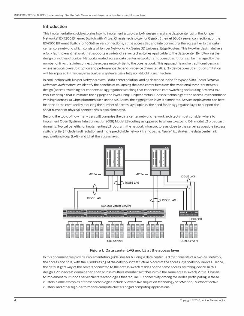
Beyond the topic of how many tiers will comprise the data center network, network architects must consider where to
implement Open Systems Interconnection (OSI) Model L3 routing, as opposed to where to expand OSI model L2 broadcast
domains. Typical benefits for implementing L3 routing in the network infrastructure as close to the server as possible (access
switching tier) include fault isolation and more predictable network traffic paths. Figure 1 illustrates the data center link
aggregation group (LAG) and L3 at the access layer.
Figure 1: Data center LAG and L3 at the access layer
In this document, we provide implementation guidelines for building a data center LAN that consists of a two-tier network,
the access and core, with the IP addressing of the network infrastructure placed at the access layer network devices. Hence,
the default gateway of the servers connected to the access switch resides on the same access switching device. In this
design, L2 broadcast domains can span across multiple member switches within the same access switch Virtual Chassis
to implement multi-node server cluster technologies that require L2 connectivity among the nodes participating in these
clusters. Some examples of these technologies include VMware live migration technology or “VMotion,” Microsoft active
clusters, and other high-performance compute clusters or grid computing applications.
EX4200 Virtual Servers
10GbE LAG
10GbE LAG
GbE Servers 10GbE Servers
EX4500
10GbE LAG
10GbE LAGMX Series MX Series
Copyright © 2010, Juniper Networks, Inc. 5
IMPLEMENTATION GUIDE - Implementing L3 at the Data Center Access Layer on Juniper Networks Infrastructure
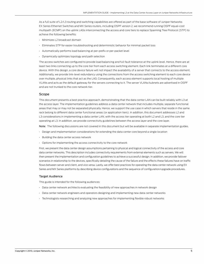
As a full suite of L2/L3 routing and switching capabilities are offered as part of the base software of Juniper Networks
EX Series Ethernet Switches and MX Series routers, including OSPF version 2, we recommend running OSPF equal-cost
multipath (ECMP) on the uplink LAGs interconnecting the access and core tiers to replace Spanning Tree Protocol (STP) to
achieve the following benefits:
• Minimizes L2 broadcast domain
• Eliminates STP for easier troubleshooting and deterministic behavior for minimal packet loss
• Automatically performs load balancing at per-prefix or per-packet level
• Dynamically optimizes topology and path selection
The access switches are configured to provide load balancing and full fault tolerance at the uplink level. Hence, there are at
least two links connecting up to the core tier from each access switching element. Each link terminates at a different core
device. With this design, a core device failure will not impact the availability of a server that connects to the access element.
Additionally, we provide link-level redundancy using the connections from the access switching element to each core device
over multiple, physical links that act as the LAG. Consequently, each access element supports local hosting of multiple
VLANs and acts as the default gateway for the servers connecting to it. The server VLANs/subnets are advertised in OSPF
and are not trunked to the core network tier.
Scope
This document presents a best practice approach, demonstrating that the data center LAN can be built reliably with L3 at
the access layer. The implementation guidelines address a data center network that includes multiple, separate functional
areas that may or may not be separated physically. Hence, we support the use case in which servers that reside in the same
rack belong to different data center functional areas (or application tiers). In addition, this document addresses L2 and
L3 considerations in implementing a data center LAN, with the access tier operating at both L2 and L3, and the core tier
operating at L3. In addition, we provide connectivity guidelines between the access layer and the core layer.
Note: The following discussions are not covered in this document but will be available in separate implementation guides.
• Design and implementation considerations for extending the data center core beyond a single location
• Building the data center access network
• Options for implementing the access connectivity to the core network
First, we present the data center design assumptions pertaining to physical and logical connectivity of the access and core
data center networks. This description includes connectivity requirements from external elements such as servers. We will
then present the implementation and configuration guidelines to achieve a successful design. In addition, we provide failover
scenarios in relationship to the devices, specifically detailing the cause of the failure and the effects these failures have on traffic
flows between server and client, and vice versa. Lastly, we offer best practices for operating the data center network using EX
Series and MX Series platforms by describing device configurations and the sequence of configuration/upgrade procedures.
Target Audience
This guide is intended for the following audiences:
• Data center network architects evaluating the feasibility of new approaches in network design
• Data center network engineers and operators designing and implementing new data center networks
• Technologists researching and analyzing new approaches for implementing flexible robust networks
6 Copyright © 2010, Juniper Networks, Inc.
IMPLEMENTATION GUIDE - Implementing L3 at the Data Center Access Layer on Juniper Networks Infrastructure
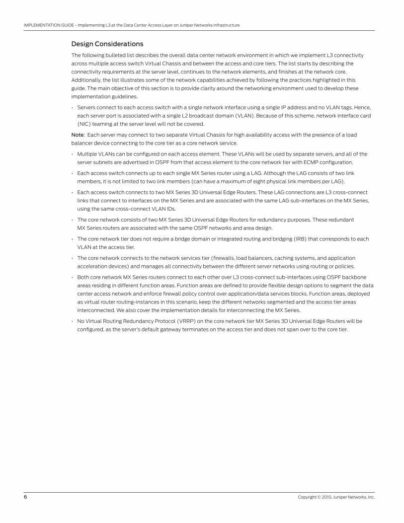
Design Considerations
The following bulleted list describes the overall data center network environment in which we implement L3 connectivity
across multiple access switch Virtual Chassis and between the access and core tiers. The list starts by describing the
connectivity requirements at the server level, continues to the network elements, and finishes at the network core.
Additionally, the list illustrates some of the network capabilities achieved by following the practices highlighted in this
guide. The main objective of this section is to provide clarity around the networking environment used to develop these
implementation guidelines.
• Servers connect to each access switch with a single network interface using a single IP address and no VLAN tags. Hence,
each server port is associated with a single L2 broadcast domain (VLAN). Because of this scheme, network interface card
(NIC) teaming at the server level will not be covered.
Note: Each server may connect to two separate Virtual Chassis for high availability access with the presence of a load
balancer device connecting to the core tier as a core network service.
• Multiple VLANs can be configured on each access element. These VLANs will be used by separate servers, and all of the
server subnets are advertised in OSPF from that access element to the core network tier with ECMP configuration.
• Each access switch connects up to each single MX Series router using a LAG. Although the LAG consists of two link
members, it is not limited to two link members (can have a maximum of eight physical link members per LAG).
• Each access switch connects to two MX Series 3D Universal Edge Routers. These LAG connections are L3 cross-connect
links that connect to interfaces on the MX Series and are associated with the same LAG sub-interfaces on the MX Series,
using the same cross-connect VLAN IDs.
• The core network consists of two MX Series 3D Universal Edge Routers for redundancy purposes. These redundant
MX Series routers are associated with the same OSPF networks and area design.
• The core network tier does not require a bridge domain or integrated routing and bridging (IRB) that corresponds to each
VLAN at the access tier.
• The core network connects to the network services tier (firewalls, load balancers, caching systems, and application
acceleration devices) and manages all connectivity between the different server networks using routing or policies.
• Both core network MX Series routers connect to each other over L3 cross-connect sub-interfaces using OSPF backbone
areas residing in different function areas. Function areas are defined to provide flexible design options to segment the data
center access network and enforce firewall policy control over application/data services blocks. Function areas, deployed
as virtual router routing-instances in this scenario, keep the different networks segmented and the access tier areas
interconnected. We also cover the implementation details for interconnecting the MX Series.
• No Virtual Routing Redundancy Protocol (VRRP) on the core network tier MX Series 3D Universal Edge Routers will be
configured, as the server’s default gateway terminates on the access tier and does not span over to the core tier.
Copyright © 2010, Juniper Networks, Inc. 7
IMPLEMENTATION GUIDE - Implementing L3 at the Data Center Access Layer on Juniper Networks Infrastructure
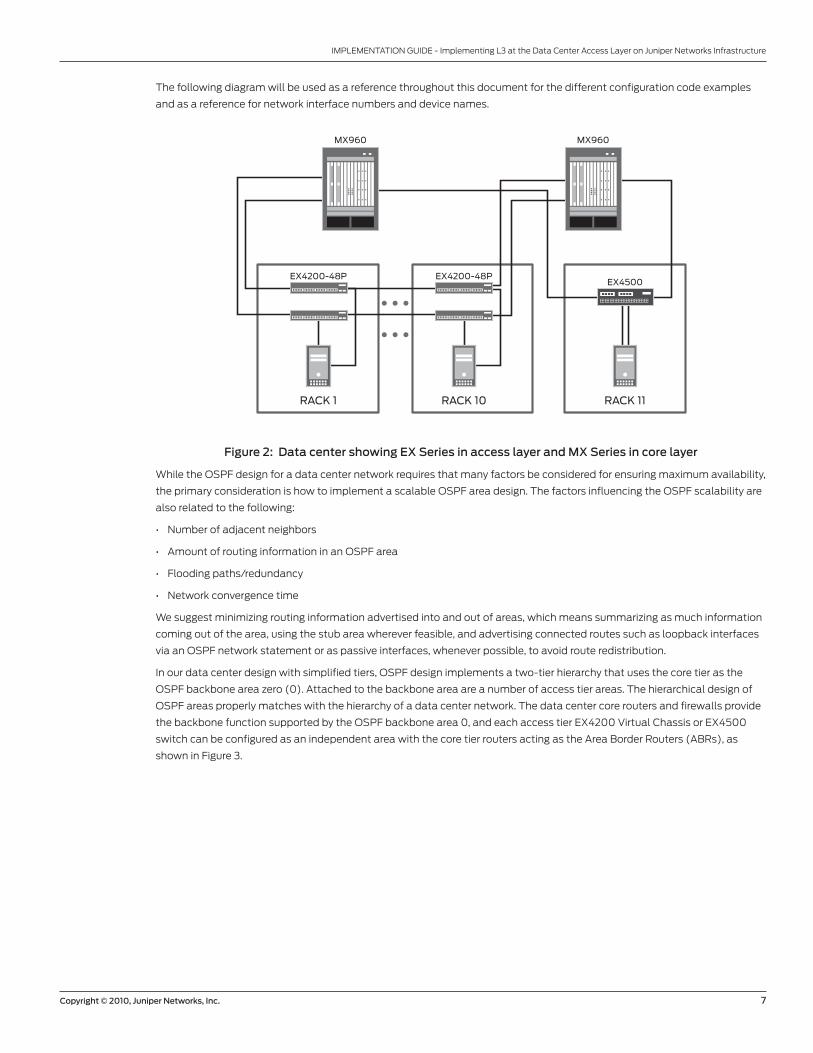
The following diagram will be used as a reference throughout this document for the different configuration code examples
and as a reference for network interface numbers and device names.
Figure 2: Data center showing EX Series in access layer and MX Series in core layer
While the OSPF design for a data center network requires that many factors be considered for ensuring maximum availability,
the primary consideration is how to implement a scalable OSPF area design. The factors influencing the OSPF scalability are
also related to the following:
• Number of adjacent neighbors
• Amount of routing information in an OSPF area
• Flooding paths/redundancy
• Network convergence time
We suggest minimizing routing information advertised into and out of areas, which means summarizing as much information
coming out of the area, using the stub area wherever feasible, and advertising connected routes such as loopback interfaces
via an OSPF network statement or as passive interfaces, whenever possible, to avoid route redistribution.
In our data center design with simplified tiers, OSPF design implements a two-tier hierarchy that uses the core tier as the
OSPF backbone area zero (0). Attached to the backbone area are a number of access tier areas. The hierarchical design of
OSPF areas properly matches with the hierarchy of a data center network. The data center core routers and firewalls provide
the backbone function supported by the OSPF backbone area 0, and each access tier EX4200 Virtual Chassis or EX4500
switch can be configured as an independent area with the core tier routers acting as the Area Border Routers (ABRs), as
shown in Figure 3.
EX4200-48P EX4200-48P
MX960MX960
EX4500
RACK 1 RACK 10 RACK 11
8 Copyright © 2010, Juniper Networks, Inc.
IMPLEMENTATION GUIDE - Implementing L3 at the Data Center Access Layer on Juniper Networks Infrastructure
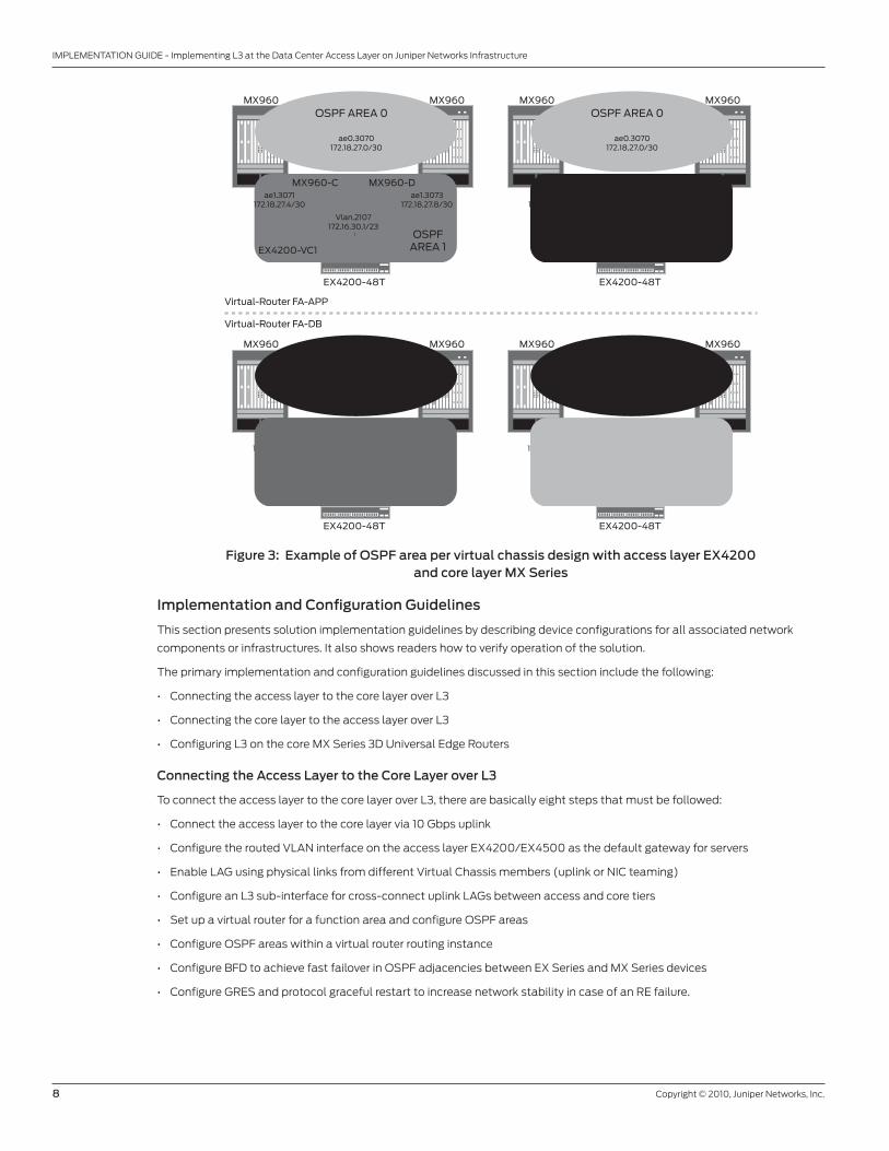
Figure 3: Example of OSPF area per virtual chassis design with access layer EX4200 and core layer MX Series
Implementation and Configuration Guidelines
This section presents solution implementation guidelines by describing device configurations for all associated network
components or infrastructures. It also shows readers how to verify operation of the solution.
The primary implementation and configuration guidelines discussed in this section include the following:
• Connecting the access layer to the core layer over L3
• Connecting the core layer to the access layer over L3
• Configuring L3 on the core MX Series 3D Universal Edge Routers
Connecting the Access Layer to the Core Layer over L3
To connect the access layer to the core layer over L3, there are basically eight steps that must be followed:
• Connect the access layer to the core layer via 10 Gbps uplink
• Configure the routed VLAN interface on the access layer EX4200/EX4500 as the default gateway for servers
• Enable LAG using physical links from different Virtual Chassis members (uplink or NIC teaming)
• Configure an L3 sub-interface for cross-connect uplink LAGs between access and core tiers
• Set up a virtual router for a function area and configure OSPF areas
• Configure OSPF areas within a virtual router routing instance
• Configure BFD to achieve fast failover in OSPF adjacencies between EX Series and MX Series devices
• Configure GRES and protocol graceful restart to increase network stability in case of an RE failure.
OSPF AREA 0
ae0.3070172.18.27.0/30
MX960 MX960
OSPFAREA 1EX4200-VC1
Virtual-Router FA-APP
Virtual-Router FA-DB
EX4200-48T
Vlan.2107172.16.30.1/23
ae1.3073172.18.27.8/30
ae1.3071172.18.27.4/30
MX960-C MX960-D
OSPF AREA 0
ae0.3070172.18.27.0/30
MX960 MX960
OSPFAREA 2EX4200-VC2
EX4200-48T
Vlan.2112172.16.50.1/23
ae2.3074172.18.27.16/30
ae2.3072172.18.27.12/30
MX960-C MX960-D
OSPF AREA 0
ae0.3080172.18.28.0/30
MX960 MX960
OSPFAREA 1EX4200-VC1
EX4200-48T
Vlan.2108172.16.34.1/23
ae1.3083172.18.28.8/30
ae1.3081172.18.28.4/30
MX960-C MX960-D
OSPF AREA 0
ae0.3080172.18.28.0/30
MX960 MX960
OSPFAREA 2EX4200-VC2
EX4200-48T
Vlan.2109172.16.38.1/23
ae2.3084172.18.28.16/30
ae2.3082172.18.28.12/30
MX960-C MX960-D
Copyright © 2010, Juniper Networks, Inc. 9
IMPLEMENTATION GUIDE - Implementing L3 at the Data Center Access Layer on Juniper Networks Infrastructure
Connect the Access Layer to the Core Layer via 10 Gbps Uplink
In this section, we describe the best practices for interconnecting the data center access layer EX4200/EX4500 switches to
the core layer MX Series routers using the 10 Gbps uplinks. On each rack, as described previously in the Design Considerations
section, we suggest two EX4200 Virtual Chassis as top-of-rack switches, where each Virtual Chassis connects to the data
center core tier that operates the MX Series routers.
We suggest that you make the redundant 10 Gbps uplink cable connections on each EX4200 Virtual Chassis on the first and
end member switches, as illustrated in Figure 2. Juniper takes this approach because these first and end member switches
are normally not configured as the Virtual Chassis primary and backup switch members (Routing Engines). This method
avoids a simultaneous failover between the uplink and Virtual Chassis Routing Engine (RE). The EX4200 Virtual Chassis
design, in this case, is also referred to as a “braided-ring” connection (connecting every other switch). This provides the
lowest intra-Virtual Chassis and uplink latency using a maximum of three meters between connected member switches.
Note: Virtual Chassis connection options in building the data center access network are not discussed, as mentioned in the
Scope section of this paper. Please refer to the Virtual Chassis Technology Best Practices for Virtual Chassis connection options.
In this scenario, the server typically connects to the EX4200 Virtual Chassis on the access layer through two NICs. Each NIC
connects to a different top-of-rack switch, as illustrated in Figure 2. With the presence of the L3 load balancing devices, and
if any of the load balancing solutions that are currently available in the market are deployed, these top-of-rack switches can
be members in separate Virtual Chassis, and the traffic from and/or to the server takes an active/active path through both
NIC connections. If L3 load balancing devices are not available, the two top-of-rack switches to which a server connects are
required to be in the same Virtual Chassis to provide L2 high availability as redundant server links. For further information
concerning server configuration, code snippets, and related screenshots, refer to Implementing VMware Server Virtualization
on Juniper Networks Infrastructure.
The key reason for this deployment is a redundant layout whereby each Virtual Chassis backs up the other. The access layer
EX4200 Virtual Chassis’ default mode uses all available uplink connections at any time, thereby distributing the traffic across
10 Gbps links based on the LAG and OSPF ECMP configuration, which we will discuss in detail in later steps.
Juniper Networks Junos® operating system implementation for the access port on the EX4200 requires that VLAN and
interfaces be associated on a one-to-one basis, while the trunk port on the EX4200 only needs to define a range of VLAN
members under the interfaces. The trunk port on the EX4200 can be used as a server connection in this case, for NIC
teaming purposes.
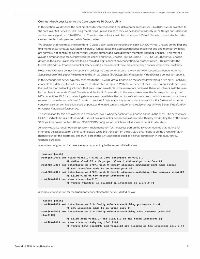
A sample configuration for the access port connecting to the server is listed below:
{master}[edit]root@EX4200# set vlans vlan2107 vlan-id 2107 interface ge-0/0/1.0 ## define vlan2107 with proper vlan-id and assign interface ##root@EX4200# set interfaces ge-0/0/1 unit 0 family ethernet-switching port-mode access ## set interface mode to be access port ##root@EX4200# set interfaces ge-0/0/1 unit 0 family ethernet-switching vlan members vlan2107 ## allow vlan on the access interface ##root@EX4200# run show vlans vlan2107 ## verify vlan2107 is allowed on interface ge-0/0/1.0 ##
A sample configuration for the trunk port connecting to the server is listed below:
{master}[edit]root@EX4200# set interfaces ae10.0 family ethernet-switching port-mode trunk ## set interface mode to be trunk port ##root@EX4200# set interfaces ae10.0 family ethernet-switching vlan members [vlan2107 vlan2112] ## allow both vlan2107 and vlan2112 on the trunk interface ##root@EX4200# run show vlans sort-by tag |find 2107 ## verify both vlan2107 and vlan2112 are allowed on the interface ae10.0 ##
10 Copyright © 2010, Juniper Networks, Inc.
IMPLEMENTATION GUIDE - Implementing L3 at the Data Center Access Layer on Juniper Networks Infrastructure
Configure the Routed VLAN Interface on the Access Layer EX4200 as the Default
Gateway for Servers
In a traditional data center network, broadcast domains consist of either physical ports connected to a single switch, or
logical ports connected to one or more switches through VLAN configurations. Switches send traffic to hosts that are part of
the same broadcast domain, but routers are needed to route traffic from one broadcast domain to another and to perform
other L3 functions such as ECMP load balancing and traffic engineering.
EX Series switches can act as L3 devices and use Routed VLAN Interface (RVI) to perform routing functions and to route
data to other L3 interfaces. This functionality eliminates both a switch and a router in the data center network. We can use
the EX4200 access switch to connect the servers and also to terminate the servers’ default gateways on the same device. In
this way, many L3 advantages such as broadcast minimization, STP elimination, and ECMP automatic load balancing can be
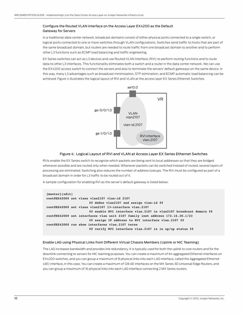
achieved. Figure 4 illustrates the logical layout of RVI and VLAN at the access layer EX Series Ethernet Switches.
Figure 4: Logical Layout of RVI and VLAN at Access Layer EX Series Ethernet Switches
RVIs enable the EX Series switch to recognize which packets are being sent to local addresses so that they are bridged
whenever possible and are routed only when needed. Whenever packets can be switched instead of routed, several layers of
processing are eliminated. Switching also reduces the number of address lookups. The RVI must be configured as part of a
broadcast domain in order for L3 traffic to be routed out of it.
A sample configuration for enabling RVI as the server’s default gateway is listed below:
VLANvlan2107
vlan-id 2107
VR
ae10.0
ge-0/0/1.0
ge-1/0/1.0RVI interface
vlan.2107
{master}[edit]root@EX4200# set vlans vlan2107 vlan-id 2107 ## define vlan2107 and assign vlan-id ##root@EX4200# set vlans vlan2107 l3-interface vlan.2107 ## enable RVI interface vlan.2107 in vlan2107 broadcast domain ##root@EX4200# set interfaces vlan unit 2107 family inet address 172.16.30.1/23 ## assign IP address to RVI interface vlan.2107 ##root@EX4200# run show interfaces vlan.2107 terse ## verify RVI interface vlan.2107 is in up/up status ##
Enable LAG using Physical Links from Different Virtual Chassis Members (Uplink or NIC Teaming)
The LAG increases bandwidth and provides link redundancy. It is typically used for both the uplink to core routers and for the
downlink connecting to servers for NIC teaming purposes. You can create a maximum of 64 aggregated Ethernet interfaces on
EX4200 switches, and you can group a maximum of 8 physical links into each LAG interface, called the Aggregated Ethernet
(AE) interface, in this case. You can create a maximum of 128 AE interfaces on the MX Series 3D Universal Edge Routers, and
you can group a maximum of 16 physical links into each LAG interface connecting 2 MX Series routers.
Copyright © 2010, Juniper Networks, Inc. 11
IMPLEMENTATION GUIDE - Implementing L3 at the Data Center Access Layer on Juniper Networks Infrastructure
Link aggregation also provides load-balanced link utilization, as hashing is done across the member links in a virtual bundle
based on the L2/L3 header. The AE interfaces can be created statically or can use the Link Aggregation Control Protocol
(LACP), as defined in the IEEE standard 802.3ad.
The physical ports in an AE virtual bundle interface are not required to be contiguous and can reside on different member
switches within a Virtual Chassis. To properly form a virtual bundle, however, the LAG member ports in an AE interface are
required to be of the same physical type, as well as the same speed and duplex.
AE interfaces must be configured correspondingly, both on the access layer EX4200 switches and on the core layer MX Series
routers or both on the EX4200 switches and on the servers configured as NIC teaming. The Junos OS implementation of LAG
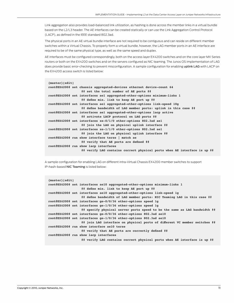
does provide basic error-checking to prevent misconfiguration. A sample configuration for enabling uplink LAG with LACP on
the EX4200 access switch is listed below:
{master}[edit]root@EX4200# set chassis aggregated-devices ethernet device-count 64 ## set the total number of AE ports ##root@EX4200# set interfaces ae1 aggregated-ether-options minimum-links 1 ## define min. link to keep AE port up ##root@EX4200# set interfaces ae1 aggregated-ether-options link-speed 10g ## define bandwidth of LAG member ports: uplink in this case ##root@EX4200# set interfaces ae1 aggregated-ether-options lacp active ## activate LACP protocol on LAG ports ##root@EX4200# set interfaces xe-0/1/0 ether-options 802.3ad ae1 ## join the LAG on physical uplink interface ##root@EX4200# set interfaces xe-1/1/0 ether-options 802.3ad ae1 ## join the LAG on physical uplink interface ##root@EX4200# run show interface terse | match ae ## verify that AE ports are defined ##root@EX4200# run show lacp interfaces ## verify LAG contains correct physical ports when AE interface is up ##
A sample configuration for enabling LAG on different intra-Virtual Chassis EX4200 member switches to support
IP-hash-based NIC Teaming is listed below:
{master}[edit]root@EX4200# set interfaces ae10 aggregated-ether-options minimum-links 1 ## define min. link to keep AE port up ##root@EX4200# set interfaces ae10 aggregated-ether-options link-speed 1g ## define bandwidth of LAG member ports: NIC Teaming LAG in this case ##root@EX4200# set interfaces ge-0/0/36 ether-options speed 1groot@EX4200# set interfaces ge-1/0/36 ether-options speed 1g ## specify physical server ports speed to be the same as LAG bandwidth ##root@EX4200# set interfaces ge-0/0/36 ether-options 802.3ad ae10 root@EX4200# set interfaces ge-1/0/36 ether-options 802.3ad ae10 ## join LAG interface on physical ports of different VC member switches ##root@EX4200# run show interface ae10 terse ## verify that AE ports are correctly defined ##root@EX4200# run show lacp interfaces
## verify LAG contains correct physical ports when AE interface is up ##
12 Copyright © 2010, Juniper Networks, Inc.
IMPLEMENTATION GUIDE - Implementing L3 at the Data Center Access Layer on Juniper Networks Infrastructure
Configure an L3 Sub-Interface for Cross-Connect Uplink LAGs Between Access and Core Tiers
EX Series switches use L3 sub-interfaces to divide a physical interface into multiple logical interfaces, each corresponding to
a VLAN. The switch uses the L3 sub-interfaces to route traffic. To configure L3 sub-interfaces, you enable VLAN tagging and
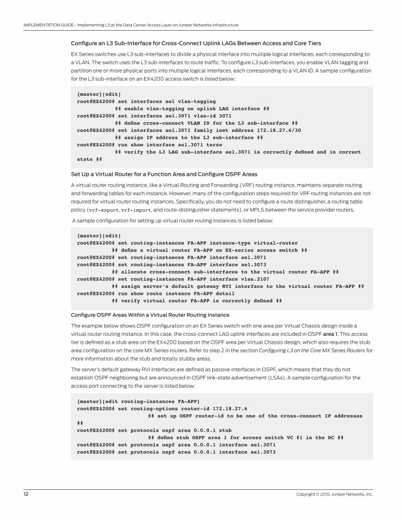
partition one or more physical ports into multiple logical interfaces, each corresponding to a VLAN ID. A sample configuration
for the L3 sub-interface on an EX4200 access switch is listed below:
{master}[edit]root@EX4200# set interfaces ae1 vlan-tagging ## enable vlan-tagging on uplink LAG interface ##root@EX4200# set interfaces ae1.3071 vlan-id 3071 ## define cross-connect VLAN ID for the L3 sub-interface ##root@EX4200# set interfaces ae1.3071 family inet address 172.18.27.6/30 ## assign IP address to the L3 sub-interface ##root@EX4200# run show interface ae1.3071 terse ## verify the L3 LAG sub-interface ae1.3071 is correctly defined and in correct state ##
Set Up a Virtual Router for a Function Area and Configure OSPF Areas
A virtual router routing instance, like a Virtual Routing and Forwarding (VRF) routing instance, maintains separate routing
and forwarding tables for each instance. However, many of the configuration steps required for VRF routing instances are not
required for virtual router routing instances. Specifically, you do not need to configure a route distinguisher, a routing table
policy (vrf-export, vrf-import, and route-distinguisher statements), or MPLS between the service provider routers.
A sample configuration for setting up virtual router routing instances is listed below:
{master}[edit]root@EX4200# set routing-instances FA-APP instance-type virtual-router ## define a virtual router FA-APP on EX-series access switch ##root@EX4200# set routing-instances FA-APP interface ae1.3071root@EX4200# set routing-instances FA-APP interface ae1.3073 ## allocate cross-connect sub-interfaces to the virtual router FA-APP ##root@EX4200# set routing-instances FA-APP interface vlan.2107 ## assign server’s default gateway RVI interface to the virtual router FA-APP ##root@EX4200# run show route instance FA-APP detail ## verify virtual router FA-APP is correctly defined ##
Configure OSPF Areas Within a Virtual Router Routing Instance
The example below shows OSPF configuration on an EX Series switch with one area per Virtual Chassis design inside a
virtual router routing instance. In this case, the cross-connect LAG uplink interfaces are included in OSPF area 1. This access
tier is defined as a stub area on the EX4200 based on the OSPF area per Virtual Chassis design, which also requires the stub
area configuration on the core MX Series routers. Refer to step 2 in the section Configuring L3 on the Core MX Series Routers for
more information about the stub and totally stubby areas.
The server’s default gateway RVI interfaces are defined as passive interfaces in OSPF, which means that they do not
establish OSPF neighboring but are announced in OSPF link-state advertisement (LSAs). A sample configuration for the
access port connecting to the server is listed below:
{master}[edit routing-instances FA-APP]root@EX4200# set routing-options router-id 172.18.27.6 ## set up OSPF router-id to be one of the cross-connect IP addresses ##root@EX4200# set protocols ospf area 0.0.0.1 stub ## define stub OSPF area 1 for access switch VC #1 in the DC ##root@EX4200# set protocols ospf area 0.0.0.1 interface ae1.3071root@EX4200# set protocols ospf area 0.0.0.1 interface ae1.3073
Copyright © 2010, Juniper Networks, Inc. 13
IMPLEMENTATION GUIDE - Implementing L3 at the Data Center Access Layer on Juniper Networks Infrastructure
## include cross-connect LAG uplink interfaces in OSPF area 1 ##root@EX4200# set protocols ospf area 0.0.0.1 interface vlan.2107 passive ## announce server’s default gateway vlan.2107 in OSPF but set as passive interface ##root@EX4200# run show ospf overview instance FA-APP ## verify OSPF is correctly defined in routing instance FA-APP ##
Configure BFD to Achieve Fast Failover in OSPF Adjacencies between EX Series and MX Series Devices
The Bidirectional Forwarding Detection (BFD) protocol is a simple hello mechanism that detects failures in a network. Hello
packets are sent at a specified, regular interval. A neighbor failure is detected when the router stops receiving a reply after a
specified interval.
BFD works with a wide variety of network environments and topologies. BFD failure detection times can be much shorter
than OSPF detection times, providing faster reaction times to various kinds of failures in the network. These timers are also
adaptive. For example, a timer can adapt to a higher value if the adjacency fails, or a neighbor can negotiate a higher value for
a timer than the one configured.
A sample configuration for enabling BFD fast failover mechanism on OSPF neighboring interfaces is listed below:
{master}[edit routing-instances FA-APP protocols ospf]root@EX4200# set area 0.0.0.1 interface ae1.3071 bfd-liveness-detection minimum-interval 500 root@EX4200# set area 0.0.0.1 interface ae2.3073 bfd-liveness-detection minimum-interval 500 ## enable BFD on OSPF adjacencies and set min. transit and receive interval to 500 ms ##
Note: Specifying an interval less than 300 ms can cause undesired BFD flapping.
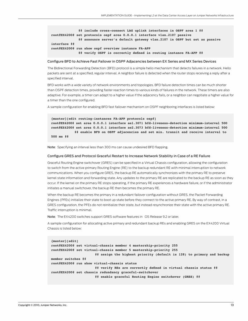
Configure GRES and Protocol Graceful Restart to Increase Network Stability in Case of a RE Failure
Graceful Routing Engine switchover (GRES) can be specified in a Virtual Chassis configuration, allowing the configuration
to switch from the active primary Routing Engine (RE) to the backup redundant RE with minimal interruption to network
communications. When you configure GRES, the backup RE automatically synchronizes with the primary RE to preserve
kernel state information and forwarding state. Any updates to the primary RE are replicated to the backup RE as soon as they
occur. If the kernel on the primary RE stops operating, if the primary RE experiences a hardware failure, or if the administrator
initiates a manual switchover, the backup RE then becomes the primary RE.
When the backup RE becomes the primary in a redundant failover configuration without GRES, the Packet Forwarding
Engines (PFEs) initialize their state to boot up state before they connect to the active primary RE. By way of contrast, in a
GRES configuration, the PFEs do not reinitialize their state, but instead resynchronize their state with the active primary RE.
Traffic interruption is minimal.
Note: The EX4200 switches support GRES software features in OS Release 9.2 or later.
A sample configuration for allocating active primary and redundant backup REs and enabling GRES on the EX4200 Virtual
Chassis is listed below:
{master}[edit]root@EX4200# set virtual-chassis member 4 mastership-priority 255 root@EX4200# set virtual-chassis member 5 mastership-priority 255 ## assign the highest priority (default is 128) to primary and backup member switches ##root@EX4200# run show virtual-chassis status ## verify REs are correctly defined in virtual chassis status ##root@EX4200# set chassis redundancy graceful-switchover ## enable graceful Routing Engine switchover (GRES) ##
14 Copyright © 2010, Juniper Networks, Inc.
IMPLEMENTATION GUIDE - Implementing L3 at the Data Center Access Layer on Juniper Networks Infrastructure
GRES does not preserve the control plane for protocol restarts. Neighboring routers detect that the router has experienced a
restart and react to the event in a manner prescribed by individual routing protocol specifications. To preserve routing during
a switchover, GRES must be combined with either graceful restart protocol extensions or nonstop active routing (NSR). NSR
is supported on the MX Series, but not currently on the EX4200 switches. Graceful restart for a virtual router functions like a
graceful restart does in the main router. The only difference is the location of the graceful-restart statement. When you
configure graceful restart, you also must include the commit synchronize statement at the [edit system] hierarchy level so
that configuration changes are synchronized on both REs.
A sample configuration for enabling graceful restart for routing protocol globally on an EX4200 virtual router is listed below:
{master}[edit]root@EX4200# set routing-instances FA-APP routing-options graceful-restart ## enable graceful or hitless routing restart options ##root@EX4200# set system commit synchronize ## synchronize configuration changes on both REs ##
Note: If you configure both BFD and graceful restart within the OSPF protocol, graceful restart may not work as expected.
Configuring EX4500 Access Switch
The configuration on the EX4500 access switch is similar to the configuration on the EX4200 Virtual Chassis access
switches.
Connecting the Core to the Access Layer over L3
To connect the core layer to the access layer over L3, you must perform the following major steps:
• Enable LAG on the MX Series router for connecting to access layer switches
• Configure an L3 sub-interface for cross-connect uplinks between access and core tiers
• Configure OSPF adjacencies within a virtual router on core MX Series routers
• Configure BFD to achieve fast failover in OSPF adjacencies between EX Series and MX Series devices
• Configure GRES and NSR to increase network stability in case of a Routing Engine failure
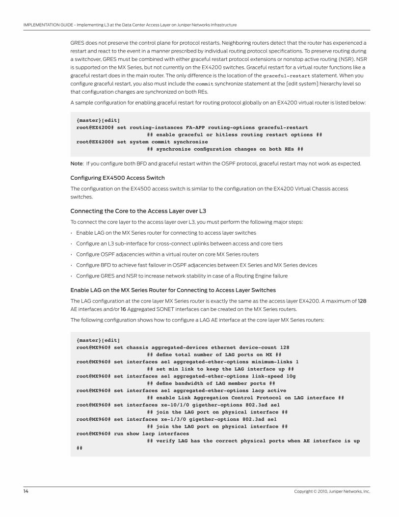
Enable LAG on the MX Series Router for Connecting to Access Layer Switches
The LAG configuration at the core layer MX Series router is exactly the same as the access layer EX4200. A maximum of 128
AE interfaces and/or 16 Aggregated SONET interfaces can be created on the MX Series routers.
The following configuration shows how to configure a LAG AE interface at the core layer MX Series routers:
{master}[edit]root@MX960# set chassis aggregated-devices ethernet device-count 128 ## define total number of LAG ports on MX ##root@MX960# set interfaces ae1 aggregated-ether-options minimum-links 1 ## set min link to keep the LAG interface up ##root@MX960# set interfaces ae1 aggregated-ether-options link-speed 10g ## define bandwidth of LAG member ports ##root@MX960# set interfaces ae1 aggregated-ether-options lacp active ## enable Link Aggregation Control Protocol on LAG interface ##root@MX960# set interfaces xe-10/1/0 gigether-options 802.3ad ae1 ## join the LAG port on physical interface ##root@MX960# set interfaces xe-1/3/0 gigether-options 802.3ad ae1 ## join the LAG port on physical interface ##root@MX960# run show lacp interfaces ## verify LAG has the correct physical ports when AE interface is up ##
Copyright © 2010, Juniper Networks, Inc. 15
IMPLEMENTATION GUIDE - Implementing L3 at the Data Center Access Layer on Juniper Networks Infrastructure
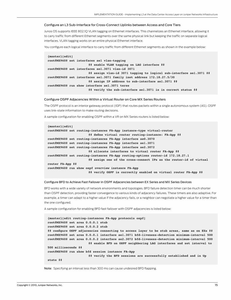
Configure an L3 Sub-Interface for Cross-Connect Uplinks between Access and Core Tiers
Junos OS supports IEEE 802.1Q VLAN tagging on Ethernet interfaces. This channelizes an Ethernet interface, allowing it
to carry traffic from different Ethernet segments over the same physical link but keeping the traffic on separate logical
interfaces. VLAN tagging works on an entire physical Ethernet interface.
You configure each logical interface to carry traffic from different Ethernet segments as shown in the example below:
{master}[edit]root@MX960# set interfaces ae1 vlan-tagging ## enable VLAN tagging on LAG interface ##root@MX960# set interfaces ae1.3071 vlan-id 3071 ## assign vlan-id 3071 tagging to logical sub-interface ae1.3071 ##root@MX960# set interfaces ae1.3071 family inet address 172.18.27.5/30 ## assign IP address to sub-interface ae1.3071 ##root@MX960# run show interface ae1.3071 terse ## verify the sub-interface ae1.3071 is in correct status ##
Configure OSPF Adjacencies Within a Virtual Router on Core MX Series Routers
The OSPF protocol is an interior gateway protocol (IGP) that routes packets within a single autonomous system (AS). OSPF
uses link-state information to make routing decisions.
A sample configuration for enabling OSPF within a VR on MX Series routers is listed below:
{master}[edit]root@MX960# set routing-instances FA-App instance-type virtual-router ## define virtual router routing-instance: FA-App ##root@MX960# set routing-instances FA-App interface ae0.3070root@MX960# set routing-instances FA-App interface ae1.3071root@MX960# set routing-instances FA-App interface ae2.3072 ## allocate interfaces to virtual router FA-App ##root@MX960# set routing-instances FA-App routing-options router-id 172.18.27.1 ## assign one of the cross-connect IPs as the router-id of virtual router FA-App ##root@MX960# run show ospf overview instance FA-App ## verify OSPF is correctly enabled on virtual router FA-App ##
Configure BFD to Achieve Fast Failover in OSPF Adjacencies between EX Series and MX Series Devices
BFD works with a wide variety of network environments and topologies. BFD failure detection timer can be much shorter
than OSPF detection, providing faster convergence to various kinds of adjacency failures. These timers are also adaptive. For
example, a timer can adapt to a higher value if the adjacency fails, or a neighbor can negotiate a higher value for a timer than
the one configured.
A sample configuration for enabling BFD fast failover with OSPF adjacencies is listed below:
{master}[edit routing-instances FA-App protocols ospf]root@MX960# set area 0.0.0.1 stub root@MX960# set area 0.0.0.2 stub ## configure OSPF adjacencies connecting to access layer to be stub areas, same as on EXs ##root@MX960# set area 0.0.0.1 interface ae1.3071 bfd-liveness-detection minimum-interval 500root@MX960# set area 0.0.0.2 interface ae2.3072 bfd-liveness-detection minimum-interval 500 ## enable BFD on OSPF neighboring LAG interfaces and set interval to 500 milliseconds ##root@MX960# run show bfd session instance FA-App ## verify the BFD sessions are successfully established and in Up state ##
Note: Specifying an interval less than 300 ms can cause undesired BFD flapping.
16 Copyright © 2010, Juniper Networks, Inc.
IMPLEMENTATION GUIDE - Implementing L3 at the Data Center Access Layer on Juniper Networks Infrastructure
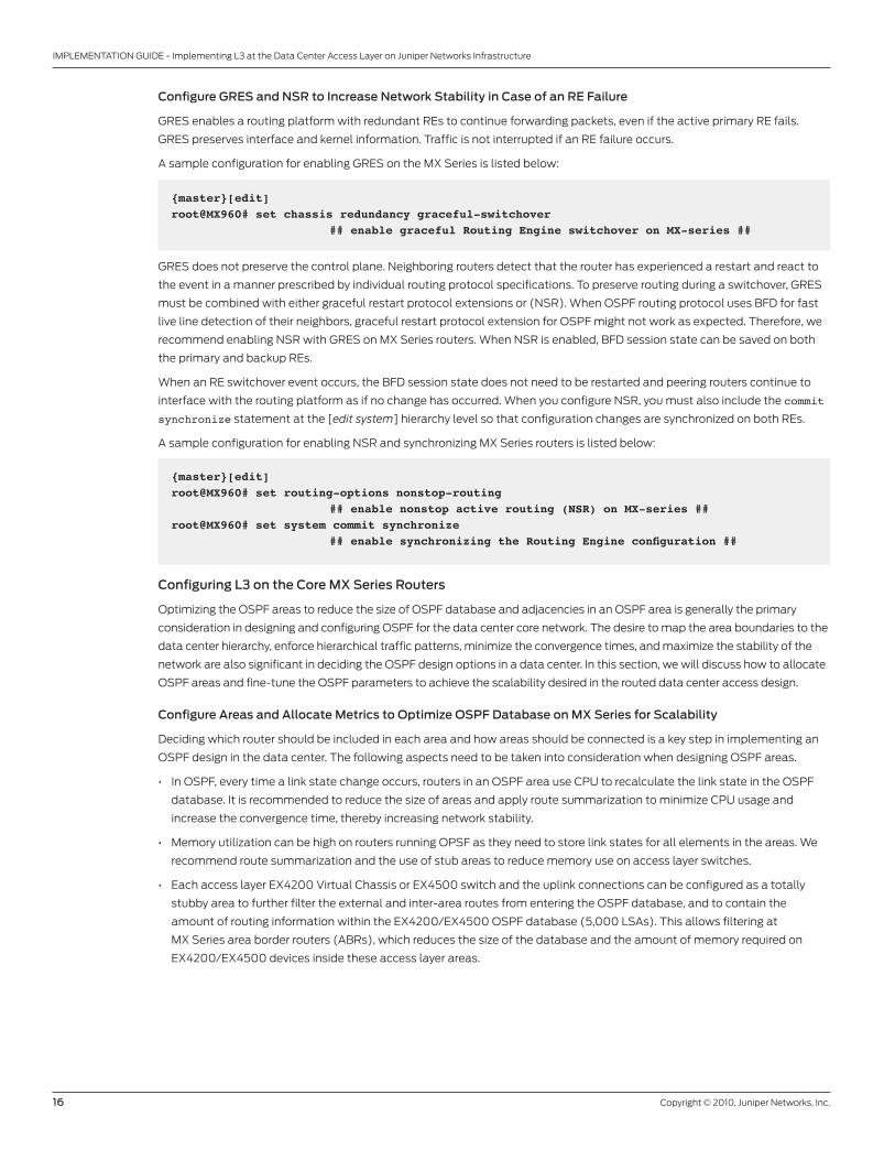
Configure GRES and NSR to Increase Network Stability in Case of an RE Failure
GRES enables a routing platform with redundant REs to continue forwarding packets, even if the active primary RE fails.
GRES preserves interface and kernel information. Traffic is not interrupted if an RE failure occurs.
A sample configuration for enabling GRES on the MX Series is listed below:
{master}[edit]root@MX960# set chassis redundancy graceful-switchover ## enable graceful Routing Engine switchover on MX-series ##
GRES does not preserve the control plane. Neighboring routers detect that the router has experienced a restart and react to
the event in a manner prescribed by individual routing protocol specifications. To preserve routing during a switchover, GRES
must be combined with either graceful restart protocol extensions or (NSR). When OSPF routing protocol uses BFD for fast
live line detection of their neighbors, graceful restart protocol extension for OSPF might not work as expected. Therefore, we
recommend enabling NSR with GRES on MX Series routers. When NSR is enabled, BFD session state can be saved on both
the primary and backup REs.
When an RE switchover event occurs, the BFD session state does not need to be restarted and peering routers continue to
interface with the routing platform as if no change has occurred. When you configure NSR, you must also include the commit
synchronize statement at the [edit system] hierarchy level so that configuration changes are synchronized on both REs.
A sample configuration for enabling NSR and synchronizing MX Series routers is listed below:
{master}[edit]root@MX960# set routing-options nonstop-routing ## enable nonstop active routing (NSR) on MX-series ##root@MX960# set system commit synchronize ## enable synchronizing the Routing Engine configuration ##
Configuring L3 on the Core MX Series Routers
Optimizing the OSPF areas to reduce the size of OSPF database and adjacencies in an OSPF area is generally the primary
consideration in designing and configuring OSPF for the data center core network. The desire to map the area boundaries to the
data center hierarchy, enforce hierarchical traffic patterns, minimize the convergence times, and maximize the stability of the
network are also significant in deciding the OSPF design options in a data center. In this section, we will discuss how to allocate
OSPF areas and fine-tune the OSPF parameters to achieve the scalability desired in the routed data center access design.
Configure Areas and Allocate Metrics to Optimize OSPF Database on MX Series for Scalability
Deciding which router should be included in each area and how areas should be connected is a key step in implementing an
OSPF design in the data center. The following aspects need to be taken into consideration when designing OSPF areas.
• In OSPF, every time a link state change occurs, routers in an OSPF area use CPU to recalculate the link state in the OSPF
database. It is recommended to reduce the size of areas and apply route summarization to minimize CPU usage and
increase the convergence time, thereby increasing network stability.
• Memory utilization can be high on routers running OPSF as they need to store link states for all elements in the areas. We
recommend route summarization and the use of stub areas to reduce memory use on access layer switches.
• Each access layer EX4200 Virtual Chassis or EX4500 switch and the uplink connections can be configured as a totally
stubby area to further filter the external and inter-area routes from entering the OSPF database, and to contain the
amount of routing information within the EX4200/EX4500 OSPF database (5,000 LSAs). This allows filtering at
MX Series area border routers (ABRs), which reduces the size of the database and the amount of memory required on
EX4200/EX4500 devices inside these access layer areas.

Copyright © 2010, Juniper Networks, Inc. 17
IMPLEMENTATION GUIDE - Implementing L3 at the Data Center Access Layer on Juniper Networks Infrastructure
• Route summarization can be configured between access tier areas and the backbone area, and can increase network
scalability by reducing the routing table size and the convergence time. The effectiveness of route summarization depends
highly on the IP addressing scheme implemented in the data center network.
• Each interface running OSPF adjacencies is assigned with a metric, which is a number that is inversely proportional to the
bandwidth of the interface. The metric of the OSPF interface can also be tuned by manual configuration to control the
traffic flow in the data center network. For example, traffic from one access layer Virtual Chassis to another Virtual Chassis
should always go through one core layer MX Series, but not both of the core routers, as illustrated in Figure 5.
Figure 5: Example of OSPF areas and metrics in a data center network
A sample configuration for configuring OSPF metrics and totally stubby areas on MX Series routers is listed below:
EX4200-VC1
ae1.3071metric 2000
ae2.3072metric 2000
AREA 1
OSPF AREA 0
VR: FA-App
AREA 2
LAYER 2
LAYER 3
ae1.3073metric 2000
ae1.3070metric 500
ae2.3074metric 2000
MX960-A
EX4200-VC2
vlan,2112172.16.50.1/24
vlan,2107172.16.30.1/24
Server 2Server 1
MX960-B
{master} [edit routing-instances FA-App protocols ospf]root@MX960# set area 0.0.0.0 interface ae0.3070 metric 500 ## assign metric 500 to inter-core MXs connection area 0 ##root@MX960# set area 0.0.0.1 stub default-metric 1000 ## enable default route with metric 1000 in totally stubby area 1 to access layer VC #1 ##root@MX960# set area 0.0.0.1 interface ae1.3071 metric 2000 ## allocate downlinks connecting to access layer VC #1 into area 1 with higher metric 2000 ##root@MX960# set area 0.0.0.2 stub default-metric 1000 root@MX960# set area 0.0.0.2 interface ae2.3072 metric 2000 ## allocate downlinks connecting to access layer VC #2 to area 2 with higher metric 2000 ##root@MX960# run show ospf overview instance FA-Approot@MX960# run show ospf neighbor instance FA-App ## verify OSPF areas are correctly defined and neighbors are in Full state ##
18 Copyright © 2010, Juniper Networks, Inc.
IMPLEMENTATION GUIDE - Implementing L3 at the Data Center Access Layer on Juniper Networks Infrastructure
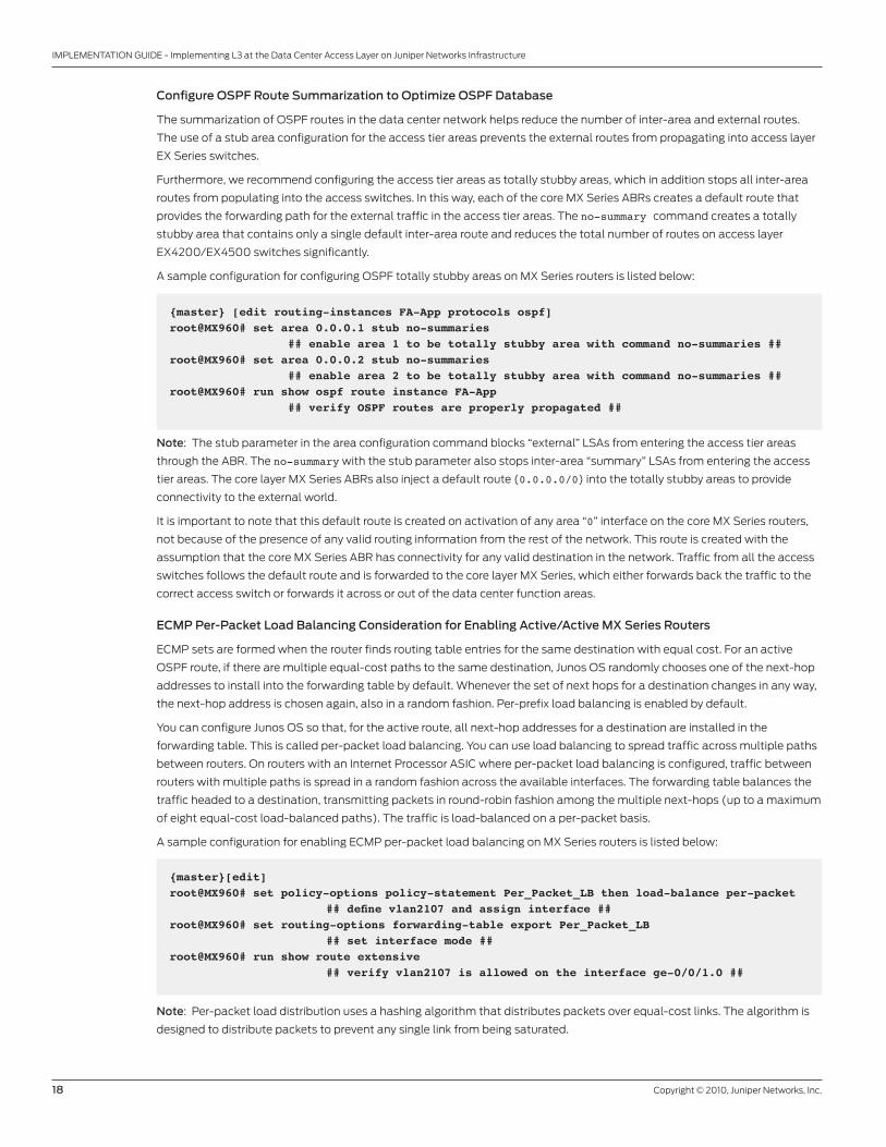
Configure OSPF Route Summarization to Optimize OSPF Database
The summarization of OSPF routes in the data center network helps reduce the number of inter-area and external routes.
The use of a stub area configuration for the access tier areas prevents the external routes from propagating into access layer
EX Series switches.
Furthermore, we recommend configuring the access tier areas as totally stubby areas, which in addition stops all inter-area
routes from populating into the access switches. In this way, each of the core MX Series ABRs creates a default route that
provides the forwarding path for the external traffic in the access tier areas. The no-summary command creates a totally
stubby area that contains only a single default inter-area route and reduces the total number of routes on access layer
EX4200/EX4500 switches significantly.
A sample configuration for configuring OSPF totally stubby areas on MX Series routers is listed below:
{master} [edit routing-instances FA-App protocols ospf]root@MX960# set area 0.0.0.1 stub no-summaries ## enable area 1 to be totally stubby area with command no-summaries ##root@MX960# set area 0.0.0.2 stub no-summaries ## enable area 2 to be totally stubby area with command no-summaries ##root@MX960# run show ospf route instance FA-App ## verify OSPF routes are properly propagated ##
Note: The stub parameter in the area configuration command blocks “external” LSAs from entering the access tier areas
through the ABR. The no-summary with the stub parameter also stops inter-area “summary” LSAs from entering the access
tier areas. The core layer MX Series ABRs also inject a default route (0.0.0.0/0) into the totally stubby areas to provide
connectivity to the external world.
It is important to note that this default route is created on activation of any area “0” interface on the core MX Series routers,
not because of the presence of any valid routing information from the rest of the network. This route is created with the
assumption that the core MX Series ABR has connectivity for any valid destination in the network. Traffic from all the access
switches follows the default route and is forwarded to the core layer MX Series, which either forwards back the traffic to the
correct access switch or forwards it across or out of the data center function areas.
ECMP Per-Packet Load Balancing Consideration for Enabling Active/Active MX Series Routers
ECMP sets are formed when the router finds routing table entries for the same destination with equal cost. For an active
OSPF route, if there are multiple equal-cost paths to the same destination, Junos OS randomly chooses one of the next-hop
addresses to install into the forwarding table by default. Whenever the set of next hops for a destination changes in any way,
the next-hop address is chosen again, also in a random fashion. Per-prefix load balancing is enabled by default.
You can configure Junos OS so that, for the active route, all next-hop addresses for a destination are installed in the
forwarding table. This is called per-packet load balancing. You can use load balancing to spread traffic across multiple paths
between routers. On routers with an Internet Processor ASIC where per-packet load balancing is configured, traffic between
routers with multiple paths is spread in a random fashion across the available interfaces. The forwarding table balances the
traffic headed to a destination, transmitting packets in round-robin fashion among the multiple next-hops (up to a maximum
of eight equal-cost load-balanced paths). The traffic is load-balanced on a per-packet basis.
A sample configuration for enabling ECMP per-packet load balancing on MX Series routers is listed below:
{master}[edit]root@MX960# set policy-options policy-statement Per_Packet_LB then load-balance per-packet ## define vlan2107 and assign interface ##root@MX960# set routing-options forwarding-table export Per_Packet_LB ## set interface mode ##root@MX960# run show route extensive ## verify vlan2107 is allowed on the interface ge-0/0/1.0 ##
Note: Per-packet load distribution uses a hashing algorithm that distributes packets over equal-cost links. The algorithm is
designed to distribute packets to prevent any single link from being saturated.
Copyright © 2010, Juniper Networks, Inc. 19
IMPLEMENTATION GUIDE - Implementing L3 at the Data Center Access Layer on Juniper Networks Infrastructure
Failover Scenarios
This section presents three failover scenarios that may occur, and in particular describes the cause of each failover and the
effects the failovers have upon northbound and southbound traffic flows.
• Access switch/Virtual Chassis failure with or without load balancing
• Uplink from access switch/Virtual Chassis to MX Series failure
• Active MX Series device failure
To increase network uptime, we use redundant links to interconnect access layer switches to the core layer and to connect
dual-homed servers to the access switches in the data center. For path redundancy and fast failover at L3, switches
that support 802.3ad link aggregation and BFD provide faster recovery from a link failure compared to the original OSPF
convergence. The EX4200 access switch also offers GRES and graceful restart protocol extension features as a faster, easier-
to-implement alternative to the L2 STP deployment. There are three failover scenarios that we would like to discuss in the
following sections. We discuss these failover scenarios for both the northbound (server-to-client) and southbound (client-
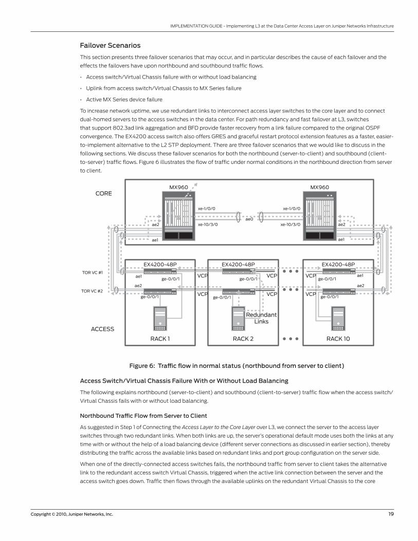
to-server) traffic flows. Figure 6 illustrates the flow of traffic under normal conditions in the northbound direction from server
to client.
Figure 6: Traffic flow in normal status (northbound from server to client)
Access Switch/Virtual Chassis Failure With or Without Load Balancing
The following explains northbound (server-to-client) and southbound (client-to-server) traffic flow when the access switch/
Virtual Chassis fails with or without load balancing.
Northbound Traffic Flow from Server to Client
As suggested in Step 1 of Connecting the Access Layer to the Core Layer over L3, we connect the server to the access layer
switches through two redundant links. When both links are up, the server’s operational default mode uses both the links at any
time with or without the help of a load balancing device (different server connections as discussed in earlier section), thereby
distributing the traffic across the available links based on redundant links and port group configuration on the server side.
When one of the directly-connected access switches fails, the northbound traffic from server to client takes the alternative
link to the redundant access switch Virtual Chassis, triggered when the active link connection between the server and the
access switch goes down. Traffic then flows through the available uplinks on the redundant Virtual Chassis to the core
EX4200-48P EX4200-48P
MX960
ae0ae2
ae1
ae1
ae2
ae2
ae1
ae1
ae2
MX960
EX4200-48P
RACK 1 RACK 2 RACK 10
ge-0/0/1
xe-1/0/0
xe-10/3/0
xe-1/0/0
xe-10/3/0
ge-0/0/1ge-0/0/1
ge-0/0/1
VCP
VCP
VCP
VCP
VCP
VCPge-0/0/1ge-0/0/1
RedundantLinks
TOR VC #1
TOR VC #2
ACCESS
CORE
20 Copyright © 2010, Juniper Networks, Inc.
IMPLEMENTATION GUIDE - Implementing L3 at the Data Center Access Layer on Juniper Networks Infrastructure
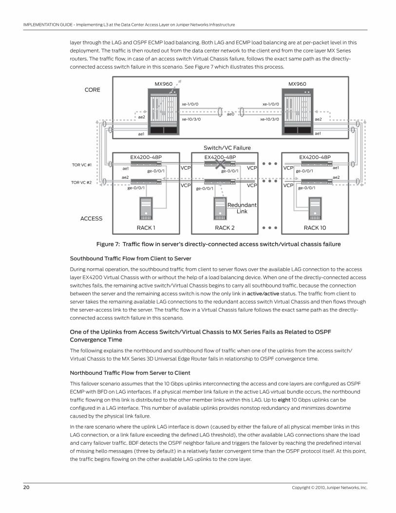
layer through the LAG and OSPF ECMP load balancing. Both LAG and ECMP load balancing are at per-packet level in this
deployment. The traffic is then routed out from the data center network to the client end from the core layer MX Series
routers. The traffic flow, in case of an access switch Virtual Chassis failure, follows the exact same path as the directly-
connected access switch failure in this scenario. See Figure 7 which illustrates this process.
Figure 7: Traffic flow in server’s directly-connected access switch/virtual chassis failure
Southbound Traffic Flow from Client to Server
During normal operation, the southbound traffic from client to server flows over the available LAG connection to the access
layer EX4200 Virtual Chassis with or without the help of a load balancing device. When one of the directly-connected access
switches fails, the remaining active switch/Virtual Chassis begins to carry all southbound traffic, because the connection
between the server and the remaining access switch is now the only link in active/active status. The traffic from client to
server takes the remaining available LAG connections to the redundant access switch Virtual Chassis and then flows through
the server-access link to the server. The traffic flow in a Virtual Chassis failure follows the exact same path as the directly-
connected access switch failure in this scenario.
One of the Uplinks from Access Switch/Virtual Chassis to MX Series Fails as Related to OSPF Convergence Time
The following explains the northbound and southbound flow of traffic when one of the uplinks from the access switch/
Virtual Chassis to the MX Series 3D Universal Edge Router fails in relationship to OSPF convergence time.
Northbound Traffic Flow from Server to Client
This failover scenario assumes that the 10 Gbps uplinks interconnecting the access and core layers are configured as OSPF
ECMP with BFD on LAG interfaces. If a physical member link failure in the active LAG virtual bundle occurs, the northbound
traffic flowing on this link is distributed to the other member links within this LAG. Up to eight 10 Gbps uplinks can be
configured in a LAG interface. This number of available uplinks provides nonstop redundancy and minimizes downtime
caused by the physical link failure.
In the rare scenario where the uplink LAG interface is down (caused by either the failure of all physical member links in this
LAG connection, or a link failure exceeding the defined LAG threshold), the other available LAG connections share the load
and carry failover traffic. BDF detects the OSPF neighbor failure and triggers the failover by reaching the predefined interval
of missing hello messages (three by default) in a relatively faster convergent time than the OSPF protocol itself. At this point,
the traffic begins flowing on the other available LAG uplinks to the core layer.
EX4200-48P EX4200-48P
MX960
ae0ae2
ae1
ae1
ae2
ae2
ae1
ae1
ae2
MX960
EX4200-48P
RACK 1 RACK 2
Switch/VC Failure
RACK 10
ge-0/0/1
xe-1/0/0
xe-10/3/0
xe-1/0/0
xe-10/3/0
ge-0/0/1ge-0/0/1
ge-0/0/1
VCP
VCP
VCP
VCP
VCP
VCPge-0/0/1ge-0/0/1
RedundantLink
TOR VC #1
TOR VC #2
ACCESS
CORE
Copyright © 2010, Juniper Networks, Inc. 21
IMPLEMENTATION GUIDE - Implementing L3 at the Data Center Access Layer on Juniper Networks Infrastructure
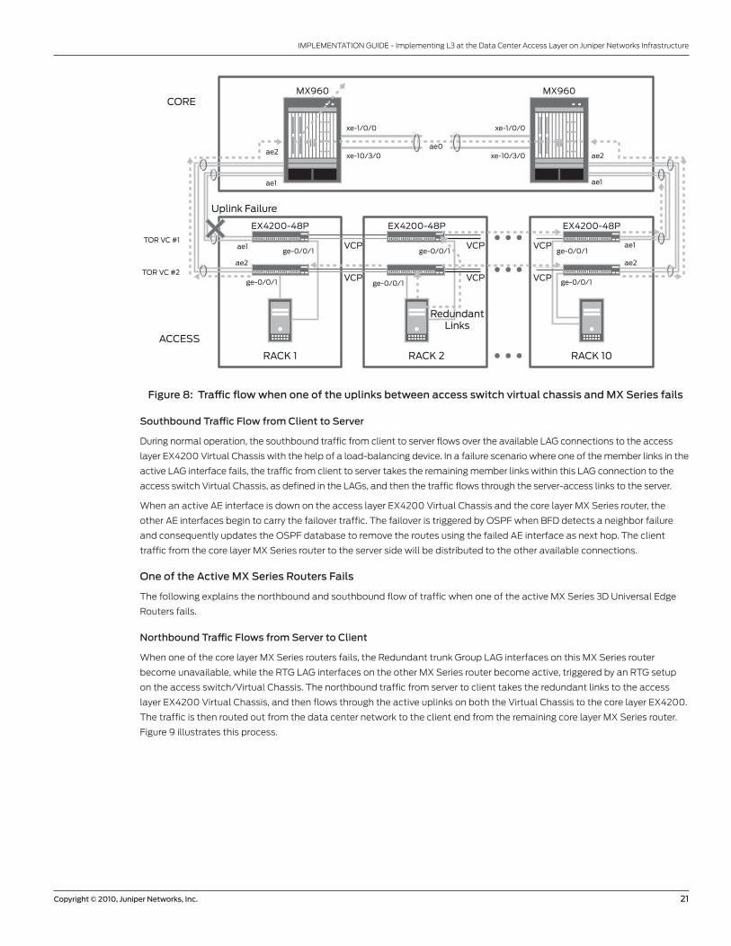
Figure 8: Traffic flow when one of the uplinks between access switch virtual chassis and MX Series fails
Southbound Traffic Flow from Client to Server
During normal operation, the southbound traffic from client to server flows over the available LAG connections to the access
layer EX4200 Virtual Chassis with the help of a load-balancing device. In a failure scenario where one of the member links in the
active LAG interface fails, the traffic from client to server takes the remaining member links within this LAG connection to the
access switch Virtual Chassis, as defined in the LAGs, and then the traffic flows through the server-access links to the server.
When an active AE interface is down on the access layer EX4200 Virtual Chassis and the core layer MX Series router, the
other AE interfaces begin to carry the failover traffic. The failover is triggered by OSPF when BFD detects a neighbor failure
and consequently updates the OSPF database to remove the routes using the failed AE interface as next hop. The client
traffic from the core layer MX Series router to the server side will be distributed to the other available connections.
One of the Active MX Series Routers Fails
The following explains the northbound and southbound flow of traffic when one of the active MX Series 3D Universal Edge
Routers fails.
Northbound Traffic Flows from Server to Client
When one of the core layer MX Series routers fails, the Redundant trunk Group LAG interfaces on this MX Series router
become unavailable, while the RTG LAG interfaces on the other MX Series router become active, triggered by an RTG setup
on the access switch/Virtual Chassis. The northbound traffic from server to client takes the redundant links to the access
layer EX4200 Virtual Chassis, and then flows through the active uplinks on both the Virtual Chassis to the core layer EX4200.
The traffic is then routed out from the data center network to the client end from the remaining core layer MX Series router.
Figure 9 illustrates this process.
EX4200-48P EX4200-48P
MX960
ae0ae2
ae1
ae1
ae2
ae2
ae1
ae1
ae2
MX960
EX4200-48P
RACK 1 RACK 2
Uplink Failure
RACK 10
ge-0/0/1
xe-1/0/0
xe-10/3/0
xe-1/0/0
xe-10/3/0
ge-0/0/1ge-0/0/1
ge-0/0/1
VCP
VCP
VCP
VCP
VCP
VCPge-0/0/1ge-0/0/1
RedundantLinks
TOR VC #1
TOR VC #2
ACCESS
CORE
22 Copyright © 2010, Juniper Networks, Inc.
IMPLEMENTATION GUIDE - Implementing L3 at the Data Center Access Layer on Juniper Networks Infrastructure
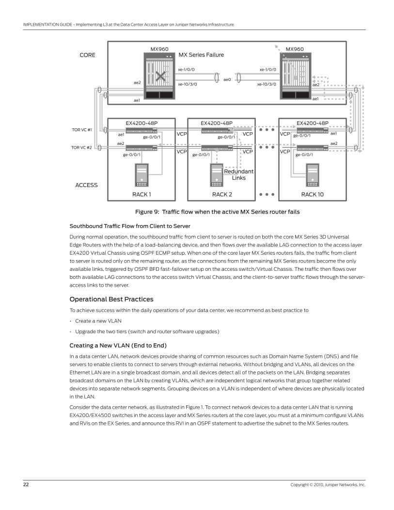
Figure 9: Traffic flow when the active MX Series router fails
Southbound Traffic Flow from Client to Server
During normal operation, the southbound traffic from client to server is routed on both the core MX Series 3D Universal
Edge Routers with the help of a load-balancing device, and then flows over the available LAG connection to the access layer
EX4200 Virtual Chassis using OSPF ECMP setup. When one of the core layer MX Series routers fails, the traffic from client
to server is routed only on the remaining router, as the connections from the remaining MX Series routers become the only
available links, triggered by OSPF BFD fast-failover setup on the access switch/Virtual Chassis. The traffic then flows over
both available LAG connections to the access switch Virtual Chassis, and the client-to-server traffic flows through the server-
access links to the server.
Operational Best Practices
To achieve success within the daily operations of your data center, we recommend as best practice to
• Create a new VLAN
• Upgrade the two tiers (switch and router software upgrades)
Creating a New VLAN (End to End)
In a data center LAN, network devices provide sharing of common resources such as Domain Name System (DNS) and file
servers to enable clients to connect to servers through external networks. Without bridging and VLANs, all devices on the
Ethernet LAN are in a single broadcast domain, and all devices detect all of the packets on the LAN. Bridging separates
broadcast domains on the LAN by creating VLANs, which are independent logical networks that group together related
devices into separate network segments. Grouping devices on a VLAN is independent of where devices are physically located
in the LAN.
Consider the data center network, as illustrated in Figure 1. To connect network devices to a data center LAN that is running
EX4200/EX4500 switches in the access layer and MX Series routers at the core layer, you must at a minimum configure VLANs
and RVIs on the EX Series, and announce this RVI in an OSPF statement to advertise the subnet to the MX Series routers.
EX4200-48P EX4200-48P
MX960
ae0ae2
ae1
ae1
ae2
ae2
ae1
ae1
ae2
MX960
EX4200-48P
RACK 1 RACK 2
MX Series Failure
RACK 10
ge-0/0/1
xe-1/0/0
xe-10/3/0
xe-1/0/0
xe-10/3/0
ge-0/0/1ge-0/0/1
ge-0/0/1
VCP
VCP
VCP
VCP
VCP
VCPge-0/0/1ge-0/0/1
RedundantLinks
TOR VC #1
TOR VC #2
ACCESS
CORE
Copyright © 2010, Juniper Networks, Inc. 23
IMPLEMENTATION GUIDE - Implementing L3 at the Data Center Access Layer on Juniper Networks Infrastructure
This is accomplished in the following steps.
1. Create a new VLAN, for example vlan2108, and associate this VLAN with the access ports connecting to the server on the
EX4200 top-of-rack Virtual Chassis.
{master}[edit]root@EX4200# set vlans vlan2108 vlan-id 2108 interface ge-0/0/12.0root@EX4200# set interfaces ge-0/0/12.0 family ethernet-switching port-mode accessroot@EX4200# set interfaces ge-0/0/12.0 family ethernet-switching vlan members vlan2108
2. Create an RVI for this vlan2108 as the server’s default gateway on the EX4200 top-of-rack Virtual Chassis.
{master}[edit]root@EX4200# set vlans vlan2108 l3-interface vlan.2108root@EX4200# set interfaces vlan unit 2108 family inet address 172.16.34.1/23
3. Announce this RVI interface vlan.2108 as a “passive” interface in OSPF and advertise this subnet to the core
MX Series routers.
{master}[edit]root@EX4200# set routing-instances FA-DB interface vlan.2108root@EX4200# set routing-instances FA-DB protocols ospf area 0.0.0.1 interface vlan.2108 passive
4. Verify that both of the core layer MX Series received this subnet as an OSPF route.
{master}[edit]root@MX960# run show route 172.16.34.1 detail table FA-DB
Upgrading the Two Tiers
Before you upgrade Junos OS for the data center MX Series and EX4200 platforms, it is important to log information about
the existing system so that after the upgrade, you can compare the same information to verify that all components are
installed and working as expected. For detailed steps on how to log the information about your system before upgrading
Junos OS, refer to www.juniper.net/techpubs/software/nog/nog-baseline/html/upgrade2.html.
You can download Junos OS for MX Series and EX4200 platforms from the Download Software menu at http://www.juniper.
net/customers/support. To download the software, you must have a Juniper Networks user account. For information on
obtaining an account, see http://www.juniper.net/entitlement/setupAccountInfo.do.
To provide a smooth software upgrade for the two tiers in the data center network, you need to install software upgrades on
the EX4200 top-of-rack Virtual Chassis, as illustrated in Figure 1.
Upgrading the Switch Software
To upgrade the switch software, perform the following steps.
1. Download the Junos OS package for the related EX4200 switch as described above.
2. Copy the software package to the switch. We recommend that you use FTP to copy the file to the /var/tmp directory.
3. To install the new package on the switch, enter the following command in operational mode:
root@EX4200> request system software add source [member member_id] reboot

24 Copyright © 2010, Juniper Networks, Inc.
IMPLEMENTATION GUIDE - Implementing L3 at the Data Center Access Layer on Juniper Networks Infrastructure
Include the member option to install the software package on only one member of a Virtual Chassis. Other members of
the Virtual Chassis are not affected.
To install the software on all members of the Virtual Chassis, do not include the member option.
Replace source with one of the following paths:
- For a software package that is installed from a local directory on the switch: /pathname/package-name
- For software packages that are downloaded and installed from a remote location:
ftp://hostname/pathname/package-name
http://hostname/pathname/package-name
For example, where package-name is jinstall-ex-9.2R2.15-domestic-signed.tgz:
4. Install the software upgrades on all EX4200 top-of-rack Virtual Chassis by following the above steps.
5. Install the Junos OS package on the backup MX Series router first in the core layer, as illustrated in Figure 1.
Upgrading the Router Software
To upgrade the router software, follow these steps:
1. Install the new software package using the request system software add command:
user@host> request system software add validate /var/tmp/jinstall-9.2R2.15–domestic-signed.tgz
2. Reboot the router to start the new software using the request system reboot command:
user@host> request system reboot
3. The software is loaded when you reboot the system. Installation takes between 5 to 10 minutes. The router then reboots
from the boot device on which the software was just installed. When the reboot is complete, the router displays the login
prompt. Log in and issue the show version command to verify the version of the software recently installed.
If the MX Series router in your network has two REs, perform a Junos OS installation on each RE separately to avoid
disrupting network operations.
Install the new Junos OS release on the backup RE, while keeping the currently running software version on the primary RE.
After making sure that the new software version is running correctly on the backup RE, switch over to the newly installed
RE to activate the new software.
Finally, install the new software on another RE, the current backup RE.
For additional information about how to perform a software upgrade for devices with redundant REs, refer to
www.juniper.net/techpubs/software/junos/junos92/swconfig-install/installing-the-software-package-on-a-router-
with-redundantrouting-engines.html#jN11F4E.
4. Perform the Junos OS upgrade on the primary MX Series router in the core layer by following the above steps.
8010022-003-EN April 2010
Copyright 2010 Juniper Networks, Inc. All rights reserved. Juniper Networks, the Juniper Networks logo, Junos, NetScreen, and ScreenOS are registered trademarks of Juniper Networks, Inc. in the United States and other countries. All other trademarks, service marks, registered marks, or registered service marks are the property of their respective owners. Juniper Networks assumes no responsibility for any inaccuracies in this document. Juniper Networks reserves the right to change, modify, transfer, or otherwise revise this publication without notice.
EMEA Headquarters
Juniper Networks Ireland
Airside Business Park
Swords, County Dublin, Ireland
Phone: 35.31.8903.600
EMEA Sales: 00800.4586.4737
Fax: 35.31.8903.601
APAC Headquarters
Juniper Networks (Hong Kong)
26/F, Cityplaza One
1111 King’s Road
Taikoo Shing, Hong Kong
Phone: 852.2332.3636
Fax: 852.2574.7803
Corporate and Sales Headquarters
Juniper Networks, Inc.
1194 North Mathilda Avenue
Sunnyvale, CA 94089 USA
Phone: 888.JUNIPER (888.586.4737)
or 408.745.2000
Fax: 408.745.2100
www.juniper.net
To purchase Juniper Networks solutions,
please contact your Juniper Networks
representative at 1-866-298-6428 or
authorized reseller.
Printed on recycled paper
Copyright © 2010, Juniper Networks, Inc. 25
IMPLEMENTATION GUIDE - Implementing L3 at the Data Center Access Layer on Juniper Networks Infrastructure
Summary
Juniper Networks offers high capacity line-rate routing and switching products with a full suite of L2/L3 routing and
switching capabilities as part of the base software, including RIP v1/v2 and OSPF. EX Series and MX Series platforms are
optimal for running data centers at great scale, and for enabling emerging trends that affect the data center such as energy
conservation, location consolidation, link utilization, and server virtualization.
This implementation guide explains how to implement a two tier LAN design in a single data center by using Juniper
Networks EX4200 Ethernet Switch with Virtual Chassis technology at the access tier, and by interconnecting the access
tier to the data center core network built on MX Series 3D Universal Edge Routers. We recommend using OSPF because it
is the best-suited dynamic routing protocol as a solution for L3 at the access layer in a large data center environment. It is
included in the base software license of EX Series and MX Series platforms and it has several advantages, such as minimizing
broadcast domains, eliminating STP, selecting optimal path and topology dynamically, load-balancing automatically with
ECMP, and using BFD to quickly converge around failed links and/or nodes in the data center infrastructure.
This implementation guide presents a middle-of-the-road approach to construct a reliable data center LAN. This guide
specifically addresses a data center network that includes multiple but separate function areas which may or may not be
separated physically. Function areas are defined to provide a flexible design option that enables segmentation and firewall
policy control within data center server networks. Therefore, we outline a use case in which servers reside in the same rack but
also can belong to different data center function areas (or application tiers). Additionally, this guide addresses considerations
for L3 at the access layer by implementing a data center LAN with the access tier operating at both L2 and L3 (L2 on
downlinks connecting to servers; L3 on uplinks connecting to the core network), and the core tier operating at L3. Lastly, we
provide implementation guidelines that focus on implementing L3 connectivity between the access and core layers.
About Juniper Networks
Juniper Networks, Inc. is the leader in high-performance networking. Juniper offers a high-performance network infrastructure
that creates a responsive and trusted environment for accelerating the deployment of services and applications over a single
network. This fuels high-performance businesses. Additional information can be found at www.juniper.net.