implementing cleaner printed wiring board … of the surface finish technologies presented in this...
TRANSCRIPT

United States Prevention, Pesticides EPA 744-R-00-002Environmental Protection And Toxic Substances March 2000Agency (7406)
Implementing Cleaner PrintedWiring Board Technologies: Surface Finishes
Design for the EnvironmentPrinted Wiring Board Project


Implementing Cleaner Printed Wiring BoardTechnologies: Surface Finishes
Design for the Environment ProgramEconomics, Exposure, and Technology Division
Office of Pollution Prevention and ToxicsU.S. Environmental Protection Agency
Washington, DC 20460


i
Table of Contents
Acknowledgments . . . . . . . . . . . . . . . . . . . . . . . . . . . . . . . . . . . . . . . . . . . . . . . . . . . . . . . . . . iii
Introduction . . . . . . . . . . . . . . . . . . . . . . . . . . . . . . . . . . . . . . . . . . . . . . . . . . . . . . . . . . . . . . . 1
Immersion Silver . . . . . . . . . . . . . . . . . . . . . . . . . . . . . . . . . . . . . . . . . . . . . . . . . . . . . . . . . . . . 5
Immersion Tin . . . . . . . . . . . . . . . . . . . . . . . . . . . . . . . . . . . . . . . . . . . . . . . . . . . . . . . . . . . . . 11
Organic Solderability Preservative (OSP) . . . . . . . . . . . . . . . . . . . . . . . . . . . . . . . . . . . . . . . . . 19
Electroless Nickel/Immersion Gold . . . . . . . . . . . . . . . . . . . . . . . . . . . . . . . . . . . . . . . . . . . . . 25
Electroless Nickel/Electroless Palladium/Immersion Gold . . . . . . . . . . . . . . . . . . . . . . . . . . . . 33
Lessons Learned . . . . . . . . . . . . . . . . . . . . . . . . . . . . . . . . . . . . . . . . . . . . . . . . . . . . . . . . . . . 37
Acronyms . . . . . . . . . . . . . . . . . . . . . . . . . . . . . . . . . . . . . . . . . . . . . . . . . . . . . . . . . . . . . . . . 39
Supplier Contacts . . . . . . . . . . . . . . . . . . . . . . . . . . . . . . . . . . . . . . . . . . . . . . . . . . . . . . . . . . 41

ii

Acknowledgments iii
Acknowledgments
This report was prepared under contract #68-W6-0021 for the U.S. Environmental Protection
Agency’s Design for the Environment (DfE) Printed Wiring Board (PWB) Surface Finishes
Project. The DfE PWB Core Group provided valuable guidance and feedback throughout the
preparation of this report. This Guide would not have been possible without the assistance of the
following suppliers, PWB manufacturers, and assemblers who provided the information
summarized in this document:
Alcatel USA
Alpha Metals
Advanced Electronics
Artetch Circuits Ltd.
Celestica
Circuit Connect
Circuit Wise
Diversified Systems
Electrochemicals, Inc.
Florida CirTech, Inc.
MacDermid Inc.
Parlex
Polyclad Technolgoies - Enthone (formerly Dexter Electronic Materials)
Quality Circuits Inc.
Raytheon
Rockwell Collins
Sanmina
Siemens AG
Solder Station One
Solectron Corporation
Technic, Inc.
Wall Industries
For additional copies of this document, or for other DfE PWB Project documents, contact:
Pollution Prevention Information Clearinghouse (PPIC) U.S. Environmental Protection Agency (Mailcode 7409)
1200 Pennsylvania Avenue, NWWashington, DC 20460
Phone: 202-260-1023 Fax: 202-260-4659 E-mail: [email protected]
DfE publications are also available on-line at: www.epa.gov/dfe

Acknowledgments iv

Introduction 1
Introduction
Surface finishes are applied to printed wiring boards (PWBs) to prevent oxidation of exposed
copper on the board, thus ensuring a solderable surface when components are added at a later
processing stage. The most widely used surface finishing process in PWB manufacturing is hot
air solder leveling (HASL). In this process, tin-lead is fused onto exposed copper surfaces. This
process may pose potential health and environmental risks due to the use of lead, and the HASL
process also generates significant quantities of excess solder that must be recycled. In addition,
HASL does not provide a level (planar) soldering surface for fine pitch components. Several
emerging surface finishes viewed as viable alternatives to HASL have been developed in recent
years. These finishes eliminate the use of lead in the surface finishing process and produce a
planar surface. For these reasons, the Design for the Environment (DfE) PWB Project team
selected the surface finishing process as the focus of a study to identify technologies that perform
competitively, are cost-effective, and pose fewer potential environmental and health risks.
Many facilities are using alternative surface finishes, but there is still a lack of information on how
to successfully implement them. Some of the best information available is from PWB
manufacturers who have already installed and are now applying the alternative finishes, and from
assemblers who work with the finishes. By sharing information, PWB manufacturers can benefit
from others’ experiences with the relatively new technologies. This report details the specific
experiences of these companies, along with their recommendations for successful implementation.
This Guide presents first-hand accounts of the problems, solutions, and time and effort involved in
implementing alternative surface finish technologies. The information presented summarizes
telephone and e-mail interviews with PWB manufacturers and assemblers currently using these
technologies, and the suppliers of the alternative technologies. With the information from these
interviews, manufacturers considering a switch to an alternative technology can benefit from the
lessons learned by those who already have made the change.

Introduction 2
Five technologies are discussed in this Guide:
g immersion silver;
g immersion tin;
g organic solderability preservative (OSP)
g electroless nickel/immersion gold; and
g electroless nickel/electroless palladium/immersion gold.
Each section includes a description of the technology, a flow chart of the process, and a
discussion of the interview results.
Twenty-five interviews were conducted (nine PWB manufacturers, ten assemblers, and six
suppliers). Each manufacturer was asked about the difficulty of the alternative finish’s installation
process, and the relative quality and operating conditions of the technology in comparison to
HASL. Assemblers were asked about the finish’s compatibility with particular types of
components and assembly processes, and whether there are considerations for rework and repair
of PWBs finished with the alternative finish. Suppliers were interviewed to gather any supplier
specifications or recommendations.
Some of the surface finish technologies presented in this document are relatively new to the
market and therefore, few facilities may be using them in a production mode. This limitation
presented some challenges in developing this document. For example, in many cases, two
different facilities using the same surface finish had two very different experiences. These
differences seem to indicate that the success of the technology may be largely dependent on site-
specific factors: from the type of product produced to the level of training of the facility staff. It
also should be noted that the comments provided in this Guide may not be representative of all
variants of a given technology; products by other suppliers may yield different results.
Additionally, for the alternative finishes that are not yet run in production at many facilities, the
number of interviews conducted was limited. Most notably, for the nickel/palladium/gold finish,
two assemblers were interviewed, however, none of the manufacturers contacted were currently
using this finish; it is estimated that only ten PWB manufacturers worldwide are known to use this
system.
This document was developed as part of the Design for the Environment (DfE) Printed Wiring
Board Project. The DfE PWB Project is a voluntary, cooperative partnership among U.S.

Introduction 3
Environmental Protection Agency (EPA); PWB industry manufacturers, assemblers, and
suppliers; the University of Tennessee Center for Clean Products and Clean Technologies; a
public interest group; and other stakeholders. The project encourages businesses to incorporate
environmental concerns into their decision-making processes, along with the traditional
parameters of cost and performance, when choosing technologies and products. Specifically,
there are three goals of the DfE PWB Surface Finishes Project:
1) to standardize existing information about surface finish technologies;
2) to present information about surface finish technologies not yet in widespread use,
so PWB manufacturers and designers can evaluate the environmental and health
risks, along with the cost and performance characteristics, of different
technologies; and
3) to encourage PWB manufacturers and designers to follow the example of this
project and systematically evaluate other technologies, practices, and procedures in
their operations that may affect the environment.
This Implementation Guide is a companion document to the full DfE project technical report for
surface finishes, the Cleaner Technologies Substitutes Assessment (CTSA). The CTSA presents
the results of an extensive evaluation of the baseline and alternative technologies including
comparative risk characterizations, cost analyses, and the results of aging, thermal shock, and
mechanical shock testing of test boards processed with the different surface finishes. This Guide
compliments the data presented in the CTSA by compiling qualitative information and advice
based on the experiences of those facilities already using the alternative finishes.
Throughout the document, the facilities interviewed are not mentioned by name. Instead, each
company has been given a code (e.g., Facility A, Facility B, etc.). It was the opinion of the
project participants that using the actual facility names might distract the reader from the
information presented on the technologies. Also, please note that mention of trade names in
this report does not constitute endorsement of the technology suppliers or recommendation foruse. Instead, the reader is encouraged to contact the suppliers for more information on their
products.

Introduction 4

Immersion Silver 5
Immersion Silver
The immersion silver finish is produced by the selective displacement of copper atoms with silver
atoms on the exposed metal surface of the PWB. To minimize silver tarnishing, an organic
inhibitor is co-deposited to form a hydrophobic layer on top of the silver. The typical thickness of
an immersion silver finish depends on the chemistry. They range from 3 to 10 microinches (0.08
to 0.25 microns) thick. There are two chemistries in production; one is operated exclusively as a
horizontal, conveyorized process, and the other can be operated either horizontally or vertically.
Immersion silver finishes are compatible with SMT, flip chip, and BGA technologies, as well as
typical through-hole components. Silver finishes appear to be compatible with all types of solder
masks, can withstand five thermal excursions during assembly, and are anticipated to have a shelf
life of up to one year if stored properly.
The immersion silver process involves five steps. Figure 1 presents a flow diagram of the steps.
A brief description of each step follows the diagram.
Cleaner
Microetch
Predip
Immersion Silver
Dry
Figure 1: Immersion Silver Process Flow

Immersion Silver 6
An acid-based cleaner removes surface oils, oxides, and any organic residues left after the solder
mask application. The cleaner provides a clean, consistent copper surface to ensure uniform
etching. The microetch solution lightly etches the exposed copper surfaces of the panel,
including the vias and barrels, to remove any chemical contamination and metal oxides present.
Etched panels are processed through a predip solution prior to silver deposition to remove any
surface oxidation that may have occurred in the previous rinse stage. The predip, which is
chemically similar to that of the silver deposition bath, also is used to protect the bath from drag-
in chemicals that may be detrimental to the deposition bath. The board is then processed through
the immersion silver bath. That bath is a pH-neutral solution that selectively deposits a 3 to 10
microinch (0.08 to 0.25 micron) layer of silver, depending on the chemistry, onto all of the
exposed copper surfaces of the PWB. Coating proceeds by a simple displacement reaction, with
silver ions displacing copper ions from the surface. The liberated copper ions are benign to the
bath chemistry and thus do not inhibit the bath effectiveness as copper concentrations increase.
Because the bath is an immersion process, plating is self-limiting and will cease when the entire
copper surface has been coated. Finally, a drying stage removes any residual moisture from the
board to prevent staining and to ensure metal quality in the through-holes. After the finish is
applied, it is recommended that the boards be stored at 72EF with 50% relative humidity.
Supplier InterviewedOne supplier, Alpha Metals Inc., was interviewed for this guide. To date, Alpha has installed 33
immersion silver systems worldwide.
Implementation at Specific FacilitiesTwo PWB manufacturers were interviewed that successfully have implemented immersion silver
surface finish lines. Facility A uses immersion silver on most boards (80%), while Facility B uses
it for only a handful of customers (5% of production). Facility A switched to immersion silver
because it is a lead-free process and is cleaner and more economical than HASL. Another reason
is that the flatter surface provides assembly benefits to customers. Facility A states that they have
gained some business with their immersion silver capabilities among customers who want an
alternative finish but find that nickel/gold is too expensive. Some customers who specify HASL
do not recognize any benefits to switching. Facility A notes that these customers are ordering
simple double-sided, plated-through boards and have not been willing to undertake evaluation
exercises.

Immersion Silver 7
Facility B also switched because of immersion silver’s superior coplanarity. In addition, they
viewed the installation as a strategic move in anticipation of increased demand for an alternative
finish in the future. Facility B has gained a small subcontract as a result of their immersion silver
capabilities and retained the half-dozen customers who requested that the line be installed, but so
far at Facility B, business has not increased significantly because of the new finish line.
At least some new equipment was installed for the new finish at each facility. Facility A added a
full new line, while Facility B installed an x-ray fluorescent instrument to measure the thickness of
the silver deposit and an auto unloader for the end of the line. Installation took one week at
Facility A, and two weeks at Facility B. At both facilities, an additional week was required for
debugging. At Facility A, two problems were encountered: poor quality of rinses, and excess
foam in the flood chamber. These problems were solved by using a distilled water feed to the
cleaner and microetch modules, and making modifications to the plumbing in the flood chamber,
respectively. Facility B faced two problems: dead pads were not plating sufficiently, and contacts
were drying before the pre-dip bath. These were solved by adjusting the pH of solutions in the
immersion silver bath and reconfiguring the rollers so that sufficient moisture was retained on the
board between steps.
When the process was put into production, Facility A encountered repeated problems with the
plating speed after a routine chemical replacement. The problem has since been resolved,
however. Facility B has not found any problems during production, but they noted that
immersion silver-finished boards are produced at a low production volume at their facility.
Comparison to HASLCycle Time. Facility A stated that the cycle time with immersion silver is twice as fast as
HASL. Facility B said that the alternative process would be about 50% faster than HASL
if all products were switched over, but this speed increase cannot be realized because the
rest of the manufacturing process is held up by boards treated with a HASL finish.
Scrap Rate and Operating Window. Both facilities have found that the scrap rate is the
same for immersion silver and HASL, but that more attention is required to attain the low
scrap rate for immersion silver because the process window is narrower. During the
process for HASL, residual flux and other contaminants are burned off. For immersion
silver, however, the residue cannot be removed as easily. Facility A was able to estimate
that the process window for immersion silver is roughly 10 times smaller than for HASL.

Immersion Silver 8
Facility B noted that poor soldermask developing can cause problems with immersion
silver.
Maintenance and Lab Analysis. The two facilities had similar experiences with time
requirements for system maintenance and lab analysis. Each stated that immersion silver
requires less maintenance time than their HASL lines. Facility A estimated the immersion
silver maintenance to be 50% of the HASL maintenance time. However, according to
these facilities, lab analysis for immersion silver is more time-consuming than for HASL.
Facility A has found that roughly twice as much time is required for lab analysis with
immersion silver.
Process Safety. At both facilities, immersion silver is preferrable from a safety standpoint.
Facility A estimated that process safety “is 100% better;” Facility B qualitatively found
that the alternative process is less noisy and has a lower fluid temperature (115oF for
immersion silver compared to 500oF for HASL).
Natural Resources. Both facilities estimated that energy use is reduced for immersion
silver compared to HASL. Facility A estimated that energy consumption was 80% less for
immersion silver as compared to that for HASL. Facility B did not quantify the difference,
but estimated that HASL energy use is higher because the solder has to be kept molten.
Facility A estimated that water use is the same, and Facility B estimated that water use is
higher for immersion silver because a water rinse is required after each stage. Regarding
waste treatment, Facility B has found that there are more waste chemicals to dispose of
with the immersion silver process.
Assemblers’ PerspectivesTwo assemblers that are working with immersion silver-finished boards were interviewed for this
Guide. Assembly Facility C stated that they have specified immersion silver for three reasons: it is
a lead-free finish, it is compatible with wire bonding, and the process is simple and low-cost.
They have found that, except for OSP, immersion silver is the least expensive of the alternative
finishes.
Facility C has not had difficulty with any particular assembly processes with immersion silver-
finished boards, and they have found that the finish works well with the solders that they use.
Slight problems have emerged, however, under certain conditions with respect to silver migration

Immersion Silver 9
and tarnishing. This is not a problem when the pads are soldered; the silver blends with the solder
and does not tarnish. However, when the board is heated without solder, the silver tarnishes.
The tarnishing results in blackened pads that have unreliable solderability properties. They noted
that this is primarily a concern with double-sided boards, on which the underside is heated as the
top is being assembled.
Rework of immersion silver-finished boards has not presented significant problems for Facility C.
Again, they mention the potential for tarnishing if there is no solder on the pads. However,
rework is almost always performed with solder on the pads, so tarnishing during rework is rarely
a concern.
Facility D has not experienced any difficulty with particular assembly processes on immersion
silver boards. The finish has performed well with the particular solders that they use. They have
found that the finish does tarnish as the board is processed through multiple reflow operations,
but this has not posed any problems to date. In their operation, the silver finish performs similarly
to a fresh OSP finish, but unlike OSP finishes, any skips in the silver finish are readily visible.
Keys to SuccessThe two manufacturing facilities both stated that
planning and communication among all parties is an
important component in the successful implementation
of the immersion silver process. Facility B
recommended that manufacturers who are installing
immersion silver should develop a relationship with the end users to determine optimal
specifications for the boards. They stressed that the implementation process must be a
partnership. Facility A added that with respect to equipment installation, the manufacturer should
arrange and chair a meeting with the chemical supplier and equipment manufacturer to ensure that
all equipment specifications are clearly defined. On a related note, Facility A recommended that
manufacturers should choose a reliable and well-proven equipment manufacturer who has
experience with flood modules.
“Arrange and chair a meeting with thechemical supplier and equipmentmanufacturer to ensure that allspecifications are defined clearly.”
- Facility A

Immersion Silver 10

Immersion Tin 11
Immersion Tin
The immersion tin process utilizes a displacement reaction between the board’s copper surface
and stannous ions in solution to reduce a layer of tin onto the copper surfaces of the PWB. The
process may be installed as a conveyorized system or in a vertical, non-conveyorized mode.
Immersion tin surfaces are compatible with SMT, flip chip, BGA technologies, and typical
through-hole components, but it is not a wire-bondable finish.
Figure 2 is a flow diagram of a typical immersion tin process. A brief description of each of the
process steps follows flow diagram shown below.
An acidic cleaner solution is used to remove surface oils and solder mask residues from the
exposed copper surfaces. Cleaning prepares the surface to ensure controlled, uniform etching.
Next, a microetch solution removes any remaining contaminants from the copper surface.
Typically, the microetch is sodium persulfate or peroxide/sulfuric solution. Etching also
chemically roughens the copper surface to promote good tin-to-copper adhesion. Etched panels
Cleaner
Microetch
Predip
Immersion Tin
Dry
Figure 2: Immersion Tin Process Flow

Immersion Tin 12
are then processed through a predip solution that is chemically similar to the tin bath, thus
protecting the plating bath from drag-in chemicals. The pre-dip is designed to evenly activate the
copper surface for uniform plating. The heated immersion tin bath deposits a thin layer of tin
onto the exposed copper circuitry through a chemical displacement reaction that deposits
stannous ions while displacing copper ions into the plating solution. The bath is considered self-
limiting because plating continues only until all the copper surfaces have been coated with a tin
deposit. The presence of a complexing agent, thiourea, prevents the copper from inhibiting the
plating process. Organic by-products from the plating process are removed by decantation. The
complexed copper is removed as a precipitate from solution by decantation. Water rinses follow
each of the steps described above, with the exception of the predip. Following the tin bath, a
drying stage removes any residual moisture from the board to prevent staining and ensure high
metal quality in the through-holes.
There are a number of different immersion tin systems available, including those based on methane
sulfonic acid, sulfate, chloride, and fluoborate chemistries. In addition, various organic additives
can be used to enhance performance, eliminate porosity, or increase polygonization to prevent
whiskering. The characteristics of the plated deposit will also vary with changes in the plating
bath chemistry. The tin concentration, thiourea concentration, copper level, organic level, and
total acidity are all likely to impact the thickness, constitution and solderability of the finish.
Suppliers InterviewedFor this Implementation Guide, two suppliers of immersion tin systems were interviewed. To
date, Dexter has completed approximately 16 installations of their FST (Flat Solderable Tin)
Immersion Tin line. Florida CirTech has approximately 80 installations of their Omikron
Immersion Tin line.
Implementation at Specific FacilitiesThree PWB manufacturers were interviewed about their experiences with immersion tin. All
three facilities run the majority of their product through their HASL line. Facility E, Facility F,
and Facility G apply an immersion tin finish to 24%, 15%, and 5% of their product, respectively.
Facility E installed their immersion tin line as part of a long-term goal to eliminate HASL, as they
find HASL to be an equipment-, energy-, and maintenance-intensive process. Facility E
recognizes that customers are reluctant to change; therefore, they expect to increase their use of
alternative finishes slowly. Facility F provides out-source services to other manufacturers. To
meet the planarity requirements that HASL cannot achieve, they run many different alternative

Immersion Tin 13
finishes. They have found immersion tin to be the only alternative technology that comes close to
HASL in terms of costs. Due to soldermask problems (described in more detail below), Facility G
plans to discontinue their use of the immersion tin finish and instead convert the tin line to an
oxidation process to promote adhesion.
Two of the facilities interviewed run a vertical, dip-tank system, and the third facility runs a
horizontal, conveyorized system. While two facilities purchased new equipment, Facility E
converted existing tanks and purchased only the peripheral equipment, such as heaters. They plan
to install a horizontal, conveyorized line when their immersion tin production reaches 50% of their
throughput. When specifying immersion tin systems, according to the suppliers, emphasis needs
to be placed on the equipment design, particularly the tin tank where quality materials and proper
filtration are critical. The rinsing stages, water flow rates, water quality, temperature, and
complete drying of the holes are also key parameters. Dry holes are best achieved by a horizontal
dryer.
All three facilities have found that customers are open to trying out new surface finishes, but
extensive testing is required to demonstrate that the alternative finish is as reliable and low-cost as
HASL. The facilities reported that even after running qualification panels, there are a fair number
of customers who still prefer the proven, long-term reliability of HASL.
All facilities interviewed installed the immersion tin line in less than a week. After getting the
system running, the facilities focused on different aspects of final system debug, as described
below.
Shelf life. To simulate long-term storage and multiple heat cycle capability, solderability
testing is often conducted after artificial aging. Because steam aging testing for
solderability is not appropriate for non-fused finishes such as immersion tin, dry heat aging
(4 to 8 hours at 155EC) or damp heat aging (85% RH at 85EC) are preferred methods.
The supplier should be consulted in the design of the coupon and of the minimum hole fill
requirements.
Facility F worked closely with their supplier to develop tests for shelf life. Every shift,
they run a 100-hole coupon and subject it to a simulated shelf life of either a 4-hour bake
(to simulate one year shelf life) or a 6-hour bake (to simulate 1.5 year shelf life). If they

Immersion Tin 14
find adjustments to the tin bath are needed, they switch to a reserve bath, while adjusting
the chemistry of the main bath.
Soldermask. Facility F initially was concerned with soldermask breakdown where the tin
leaches underneath the soldermask. Because they are an out-source facility, they work
with many different soldermasks. Most incompatibilities can be avoided by changes in
preclean procedures. There are a few soldermasks for which they do not use the
immersion tin coating. Facility G had more significant problems related to soldermask.
For a specific type of solder mask they were required to use, the residues were absorbed
into the tin and the volatiles were released during the assembly process when the boards
were pre-baked. The volatiles contaminated the surface, reducing solderability. They did
not find a solution to the problems with this particular soldermask and are therefore
discontinuing the use of the immersion tin line.
When installing a tin process, both suppliers emphasize that soldermask pre-testing is
critical. Parameters such as cure time may need to be adjusted, and precleaning may need
to be improved. Some masks, especially the newer generation of acrylic-epoxy
technologies are hydrophilic and can quickly pick up moisture and other liquid-borne
material, resulting in increased ionics. This necessitates thorough rinsing, and in some
cases, additional curing or post-cleaning. The supplier should be consulted for
recommendations.
Process control. Facility E found they had to learn to control the layers of tin. As the
copper is replaced with tin, the intermetallic becomes pure tin. When they first started
running the line, they did not conduct testing to monitor this reaction, and they
experienced consistency problems. Now they pull samples from every job and send them
out for Sequential Electrochemical Reduction Analysis (SERA) testing. With the SERA
results, they now have excellent control of the process. One of the suppliers noted that
tracking copper levels and defining and carefully controlling regeneration frequency is very
important to running the system well. Tin processes are limited by copper build up,
therefore the baths have to be disposed of and regenerated. A typical bath will be able to
process 80 to 120 sq. ft. per gallon of bath between renewal procedures. Two tin baths
are required for continuous operation, and should be factored into the installation.

Immersion Tin 15
Keeping tin in solution. At start-up, Facility G found that the tin would precipitate out
of the bath. With further investigation, they found this was caused by bath agitation from
two sources: the return flow of the tin solution back into the tank, and the use of a fine
filter (less than 5 microns) they were using to clean the bath. By lowering the return
piping to the tin bath, and replacing the 5 micron filter with a 10 - 20 micron filter,
agitation was reduced and the precipitation problem was solved.
Comparison to HASLCycle Time and Scrap Rate. The facilities interviewed saw little difference between
immersion tin and HASL regarding cycle time and scrap rate, although two facilities
mentioned that HASL boards can be reworked more easily.
Maintenance. Facility G finds the HASL line to be a bit more difficult to maintain,
primarily because of the time-consuming drossing process. Facility E and Facility F see a
more dramatic reduction in maintenance time. They estimate that the maintenance
required for the tin line is about 20% of that required for HASL. According to Facility E,
“with a 500EF solder pot with oil and flux, plus air blowing, the HASL line creates a
mess.”
Lab Analysis. Facility G said the time spent on lab analysis is about the same for
immersion tin and HASL, with daily samples sent out for each line. Facility E and Facility
F both run lab analyses more frequently for the immersion tin line than for the HASL line.
They find the additional analyses allow them to run within the tighter specifications
required for the immersion tin system.
Operating Window. The PWB manufacturers feel that the immersion tin line must be
run within the specified operating parameters. These parameters are tighter than those
required for HASL, but that there is less fluctuation in the immersion tin process if it is
operated within the specified window.
Process Safety and Natural Resources. The three facilities agreed that HASL has
greater potential process safety concerns. This is largely because of health concerns with
the lead in HASL and the potential for burns with a molten solder bath running at up to
550EF. All facilities pointed out that HASL uses significantly more energy than immersion
tin. HASL maintains the solder in a molten state at up to 550EF, but the tin bath is run at

Immersion Tin 16
about 140 - 160EF. None of the facilities see a difference in water use between HASL and
immersion tin.
Assemblers’ PerspectivesFor Assembly Facility H, the driving force for
specifying immersion tin is its ability to
produce a flat finish for fine-pitch SMT and
the associated reduction in variability. Other
benefits include improvements in hole size
tolerance and a desire to work with a lead-
free finish. Assembly Facility I was motivated
to specify an immersion tin finish for: a uniform layer thickness for improved interconnection
properties to high I/O components; an environmentally preferable finish; good
wettability/repeatability; reduced costs; and good precondition for implementing advanced
packages (area array).
The other assembler interviewed, Facility J, does not work with fine-pitch products. Their
motivation for specifying immersion tin was the cost savings. Initially, the immersion tin boards
worked very well and they started specifying that more and more boards be immersion tin
finished. After several months without a problem, however, they started experiencing serious
inconsistencies in the finish. The manufacturer they were working with was not providing boards
with consistent total coverage. Facility J could not be sure whether or not the boards were good,
and in some cases, the solderability problems were not detected until the boards were fully
populated. After working with the manufacturer to try to resolve these problems, the assembler
tried boards from a second manufacturer, but experienced the exact same problems. Facility J
could not work with the inconsistency in the finish they were seeing. The facility has since
switched back to specifying only HASL finished boards.
In comparison to other alternative surface finishes, the assemblers interviewed found immersion
tin to be the alternative surface finish that is closest to a drop-in replacement for HASL. The
immersion tin final solder joint is indistinguishable from a standard HASL (tin-lead) finish solder
joint, making the rework process with an immersion tin finish identical to rework of HASL
finished boards.
“For immersion tin, make sure you have goodquality control and testing procedures in placeand that you understand the thickness andcoverage of the tin.”
- Facility H
Immersion Tin 17
Both assemblers found that good handling practices are needed to minimize corrosion and ionic
contamination. Excess finger prints in sensitive areas can cause a decline in solderability. Clean,
lint-free gloves should be worn by anyone handling the boards. Additionally, assemblers working
with lead-free reflow soldering processes should thoroughly test compatibility with the tin finish.
Because lead-free reflow temperatures are likely to be substantially higher, the growth of
tin/copper intermetallics (which are not solderable) may be increased significantly with the higher
temperatures. Facility H also emphasized that boards with an immersion finish should not be
baked prior to assembly. Based on his experience, baking substantially degrades the solderability.
Keys to SuccessAll those interviewed, including
manufacturers, suppliers, and assemblers,
emphasized the importance of following the
suppliers' recommendations and taking the
time to fully understand the process and its
controls. This and other keys to success are summarized below:
Maintain process control. Those interviewed were all in agreement that accurate
process control is necessary to run the immersion tin line well. This includes good general
process control (e.g., establishing and maintaining control of the time, temperature, and
bath concentrations), and good calibration of test equipment. Both suppliers interviewed
noted that the customers who run the system most successfully are those that follow the
supplier’s control specifications closely.
Start with quality equipment. One of the manufacturers advocated that facilities
considering an installation should “go with an equipment vendor who has knowledge of
the immersion tin process.” The suppliers also recommended that facilities consult with
their immersion tin supplier to verify that the equipment design is compatible with the
system operation.
Verify shelf life. One of the manufacturers and all of the assemblers recommended that
facilities develop a testing protocol to verify shelf life. The manufacturer who
recommended this verification runs a test coupon every shift.
“By monitoring and controlling time, temperatureand concentrations, anyone can produce areliably solderable immersion tin surface finish.”
-Facility E

Immersion Tin 18
Limit baking. One of the suppliers recommended that any extensive baking be carried
out before plating. An assembler emphasized this further saying that boards with this
finish should not be baked prior to assembly. From this assembler’s experience, baking
substantially degrades the solderability. In particular, he recommended that immersion tin
should not be used with boards made from any material substantially more prone to
moisture absorption than typical FR4/5 materials (e.g., Epoxy Thermount) because these
materials generally need to be baked prior to assembly.
Remove moisture. A supplier stressed that proper board drying, particularly the holes, is
critical and should be done horizontally. Boards left with residual traces of moisture may
have poor solderability and/or may have corrosion problems during storage and transit.
One of the assemblers cautioned, “If you have to get the product wet for any reason prior
to completion of any first time soldering operations, be sure not to leave it wet. Blow it
off with compressed air to clear the water.”

Organic Solderability Preservative (OSP) 19
Organic Solderability Preservative (OSP)
The OSP finish is an anti-oxidant film applied to exposed copper surfaces that reacts with copper
to form an organometallic layer. This coating is nearly invisible, and may be applied either as a
thick (4 to 20 microinches / 0.1 to 0.5 microns) or thin (mono-molecular) layer. The thicker OSP
coatings are considered in this Guide. The OSP process typically is operated in a horizontal,
conveyorized mode but can be modified to run in a vertical, non-conveyorized mode. OSP
processes are compatible with SMT, flip chip, and BGA technologies, as well as with typical
through-hole components. OSP surfaces are compatible with all soldermasks and have a shelf life
of six months.
The flow diagram below presents the sequence of steps of the typical OSP process. A brief
description of each process step follows the diagram.
Cleaner
Microetch
Air Knife
OSP
Dry
Air Knife
Figure 3: OSP Process Flow

Organic Solderability Preservative (OSP) 20
The acidic cleaner solution removes surface oils and soldermask residues from the exposed
copper surfaces. The cleaner prepares the surface to ensure the controlled, uniform etching in
subsequent steps. Next, the board is processed through the microetch solution, which typically
consists of dilute hydrochloric, sulfuric, or acetic acid. The etching of the existing copper
surfaces removes any remaining contaminants and chemically roughens the surface of the copper
to promote coating adhesion. In some processes, an air knife then removes excess solution from
the panel to limit oxidation formation on the copper surfaces prior to the OSP coating application.
This step also minimizes drag-in of sulfates, which are harmful to the OSP bath. Next, a
protective OSP layer is selectively deposited on the exposed copper surfaces by the OSP
formulation in a water and acid bath. The protective layer chemically bonds to the copper,
forming an organometallic layer that preserves the solderability of the copper surface for future
assembly. An air knife is then used again to remove excess OSP from the panel and to promote
even coating across the entire PWB surface. The air knife also minimizes the chemical losses
through drag-out from the OSP bath. Finally, warm-air drying cures the OSP coating and helps
to remove any residual moisture from the board.
Suppliers InterviewedTwo suppliers, MacDermid, Inc., and Electrochemicals, Inc., were interviewed. Among all
suppliers, approximately 450 manufacturing facilities in the United States are finishing boards with
OSP. Worldwide, approximately 1,500 facilities use OSP.
Implementation at Specific FacilitiesThree PWB manufacturing facilities were interviewed that have successfully implemented an OSP
finish line. They found that the OSP finish has performed well. At Facility K and Facility L, the
OSP finish was installed at the request of large customers that specified the finish. Facility M
installed their OSP line to reduce the use of lead. All three facilities installed the finishes five to
six years ago. Facility K and Facility M purchased entirely new equipment for the OSP line. At
Facility L, the contact did not know whether equipment was purchased or not, but knew that the
facility had at least installed new racks.
Installation of the equipment each facility was relatively straightforward. At Facility K, the
installation was completed in about a week. At Facility M, it took three or four weeks to install
the new equipment. At Facility L, the installation went smoothly, but the length of time required
for it was not known by the contact. All three facilities required some debugging/training time to
adjust to the new process.

Organic Solderability Preservative (OSP) 21
Facility K encountered two problems: the coating thickness initially was too thin, and some
staining and spotting appeared on the finish. The coating thickness problem was traced to the
microetch solution (mild sulfuric acid), two steps prior to the OSP application. The water rinse
after the microetch was not removing all of the acid, which resulted in a lower pH in the OSP bath
and ultimately a thinner finish. The problem was solved by removing the microetch from the
process. It proved to be unnecessary, and its removal allowed the OSP thickness to be controlled
precisely. The staining and spotting was traced to the OSP fluid flow rate. The flow rate was too
high, which aerated the fluid, producing bubbles. The problem was solved by adjusting the rollers
and reducing fluid flow.
Facility L did not specify any particular problems, but they did indicate that it took some time for
facility workers to learn how to operate the equipment and analyze the results. However, the
supplier and the equipment manufacturer helped the facility through the learning process.
Facility M required three months to debug their process. They encountered three problems: poor
solderability; uneven coating; and copper oxidation, which they noted was primarily a cosmetic
issue. The solderability problem was traced to the microetch bath. Unlike Facility K, Facility M
maintained the microetch step, but instead changed the bath formulation. The uneven coating was
fixed by improving the quality of the rinse water. The appearance of copper oxidation was
eliminated by switching from the formulation of their previous OSP supplier to that of their
current supplier.
In production, the OSP line has worked well for Facility L. “As long as the temperature and
exposure time are maintained properly, the same coating is obtained every time.” Facility M did
not report any recurring problems. Facility K, however, consistently has difficulties when the
production line is down for a week (i.e., Christmas or a summer shutdown). During these
shutdowns, the OSP chemicals are taken out of the system and stored in drums. When the line is
started back up, the chemicals are pumped back in. During storage, the fluid is stagnant and cool,
causing the active ingredients to crystallize against the sides of the drums. As a result, when the
fluid is pumped back into the system, it has a low OSP concentration and the coatings can be too
thin. It takes about a day to readjust the mixture. The problem though, according to Facility K, is
predictable. For the next shutdown they will experiment using stirrers to keep the stored solution
in suspension.

Organic Solderability Preservative (OSP) 22
Comparison to HASLCycle Time. The facilities found that the cycle time is comparable if not slightly faster
than for HASL. Facility K stated that OSP is “more productive,” in that with a batch
process, 20 to 24 boards can be treated in the time that 18 boards are finished with HASL.
Facility L reported that the cycle time for OSP is approximately 15 minutes; cycle time for
HASL alone is faster, but when the pre-treat, flux, and post-clean steps for HASL also are
considered, the processes take about the same amount of time.
Scrap Rate. The scrap rates at Facility K and Facility L for OSP-coated boards are much
lower. Facility K estimated that this is because OSP does not require the harsh conditions
of HASL (high temperature and exposure to flux). Facility L added that the scrap rate
also may be lower at their facility because OSP is applied after the boards are routed and
inspected. Facility M stated that the scrap rate is slightly higher for OSP, but that is
because the boards that they finish with OSP are more complex.
Maintenance and Lab Analysis. All three facilities stated that OSP has fewer system
maintenance requirements. At Facility K, the HASL equipment requires an entire shift of
down-time every two weeks for maintenance. While daily maintenance is conducted on
the OSP equipment at each facility, no long-term maintenance shutdowns are needed.
Facility L said that the maintenance of pre-treat and post-clean equipment for HASL are
the most time-consuming. Facility L noted that neither process demands much lab
analysis; their OSP chemicals are tested regularly with a UV spectrometer, and likewise
their pre-treat and post-clean rinse tanks for the HASL line are checked and replaced
frequently. Facility M said that OSP is slightly more lab intensive.
Operating Window. The three facilities have found that OSP requires relatively tight
controls. However, Facility K noted that while HASL has a more forgiving operating
window, it is also more difficult to control layer thickness and other key parameters.
Facility L said that the operating window for HASL is about the same as that for OSP,
because HASL can cause potential defects resulting from high solder temperatures, the
high-pressure air knife, and rapid thermal quenching.
Process Safety. All three facilities found that process safety is improved with OSP.
Facility K noted that the HASL line can create potentially hazardous conditions such as tin
and lead fumes, fluxes, and splattering solder. Facility L added that there are potential

Organic Solderability Preservative (OSP) 23
dangers for HASL associated with the air knife, and that an operator must stand in front
of the machine longer than is necessary for OSP, thereby increasing the potential for
exposure. Facility K added that they did not have much information about the potential
risks of OSP chemicals.
Natural Resources. Facility L has found that energy use is lower for OSP because HASL
requires higher temperatures to maintain the solder in a molten state. In comparison, OSP
only requires moderate heating of solution baths. Facility L stated that OSP water
consumption is about one-half that of HASL when considering the pre-treat and post-
clean steps, because these HASL steps involve triple rinsing. With regard to recycling,
they are able to recycle both HASL and OSP scrap boards for copper recovery. Facility L
has found that neither OSP nor HASL affects regulatory obligations, because neither
process involves the discharge of copper or lead in wastewater.
Assemblers’ PerspectivesThree assemblers who work with OSP-
coated boards were interviewed. All three
expressed that OSP requires diligence, but
provides predictable results. The three
facilities have encountered no compatibility
problems with components. Facility L (a
PWB manufacturing facility that also has
assembly operations on-site) has not had any problems with assembly processes. However,
Assembly Facility N has found that OSP can break down on multi-pass processes. All three
assemblers indicated that OSP finishes are susceptible to damage or removal when handled
poorly. Facility L warns that OSP is susceptible to water – i.e., deionized water is capable of
taking off the finish. Facility N has found that flux contamination can be a problem, and that it is
not possible to clean between soldering and reflow.
Facility D and Facility N noted that OSP and HASL boards will not exhibit the same behavior
during assembly processes. OSP boards require more heat and a more active flux to obtain the
same result obtained with HASL.
Facility D noted that the characteristics of the OSP change during multiple reflow processes. The
finish appears to become thinner, denser, and harder, like a shellac. Thay have found that this
“Don’t skimp on equipment. Some try to use oldfilm developers, then have trouble withcontamination. Most costs during operation areassociated with drag-out, which is also equipment-dependent.”
- Electrochemicals

Organic Solderability Preservative (OSP) 24
hardened finish becomes very difficult to probe through at the electrical test, and that an adequate
hole fill at wave solder is very difficult on thick boards after double-sided SMT. Also, a thin film
of soldermask contamination left on pads may not be removed during the OSP process; it cannot
be readily seen and it can seriously impact solderability of affected surfaces. Additionally, Facility
D and Facility N have found that bare copper inevitably is left on corners and edges of terminal
pads upon reflow with OSP.
Facility L and Facility N noted that reworking and repairing OSP-finished boards may require the
reapplication of OSP. If the finish is unsolderable, it has to be stripped and reapplied. Facility N
noted that this is inconvenient, but is possible. If the board has been stored beyond its shelf life
(six months to one year), it has to be recoated as well.
Switching from HASL to OSP with the same equipment can cause difficulties. Facility N
recommended that if possible, it is better to have separate equipment for the two different
processes.
Keys to SuccessManufacturers and suppliers alike stressed the importance of using good equipment for the
process. Electrochemicals stated, “Don’t skimp on equipment. Some try to use old film
developers, then have trouble with contamination. Most costs during operation are associated
with drag-out, which is also equipment-dependent.” Suppliers added that planning during the
installation process is important. Delays can be caused by having the incorrect heaters and pumps
on hand, or by indecision on whether the facility will route the boards before or after applying the
OSP.
During production, manufacturers recommended monitoring the temperature of the OSP baths.
Facility L stated, “As long as the temperature and exposure time are maintained properly, the
same coating is obtained every time.” Additionally, Facility L recommended cleaning the copper
well before applying the OSP because, as Facility D also noted, residual soldermask results in a
poor finish. Fingerprints should be avoided after the application of OSP. Finally, suppliers
recommend that after production, the boards should be packaged and stored under dry conditions.

Electroless Nickel/Immersion Gold 25
Electroless Nickel/Immersion Gold
The electroless nickel/immersion gold surface finish is applied through the deposition of an initial
layer of nickel followed by a thin, protective layer of gold onto the exposed copper surfaces of the
PWB. Nickel characteristics such as hardness, wear resistance, solderability, and uniformity of
the deposit make this a desirable alternative surface finish. The thin layer of immersion gold
preserves the solderability of the finish by preventing oxidation of the highly active nickel surface.
Nickel/gold finishes typically can withstand as many as six or more thermal excursions (heating
cycles) during assembly without losing solderability.
The process is operated in a vertical, non-conveyorized mode. An electroless nickel/immersion
gold finish is compatible with SMT, flip chip, and BGA technologies, as well as with typical
through-hole components. The finish is also aluminum wire-bondable. The high plating
temperatures and low pH of the nickel/gold plating process can be incompatible with soldermasks
with high acrylic content; however, soldermasks high in epoxy content were unaffected by the
plating solution. Nickel/gold plated boards have a shelf life of up to two years or more. Figure 4
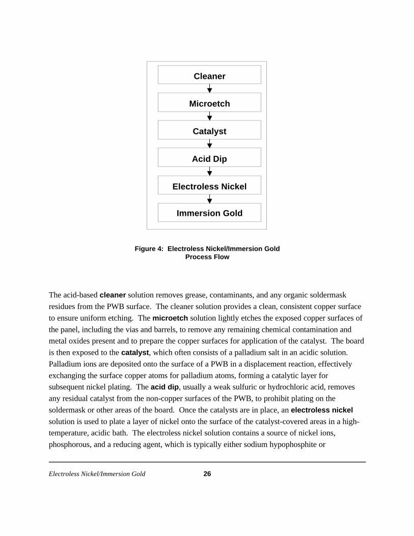
illustrates the basic steps of the electroless nickel/immersion gold process; a brief description of
each step follows the diagram.
Electroless Nickel/Immersion Gold 26
Cleaner
Microetch
Catalyst
Acid Dip
Immersion Gold
Electroless Nickel
Figure 4: Electroless Nickel/Immersion GoldProcess Flow
The acid-based cleaner solution removes grease, contaminants, and any organic soldermask
residues from the PWB surface. The cleaner solution provides a clean, consistent copper surface
to ensure uniform etching. The microetch solution lightly etches the exposed copper surfaces of
the panel, including the vias and barrels, to remove any remaining chemical contamination and
metal oxides present and to prepare the copper surfaces for application of the catalyst. The board
is then exposed to the catalyst, which often consists of a palladium salt in an acidic solution.
Palladium ions are deposited onto the surface of a PWB in a displacement reaction, effectively
exchanging the surface copper atoms for palladium atoms, forming a catalytic layer for
subsequent nickel plating. The acid dip, usually a weak sulfuric or hydrochloric acid, removes
any residual catalyst from the non-copper surfaces of the PWB, to prohibit plating on the
soldermask or other areas of the board. Once the catalysts are in place, an electroless nickel
solution is used to plate a layer of nickel onto the surface of the catalyst-covered areas in a high-
temperature, acidic bath. The electroless nickel solution contains a source of nickel ions,
phosphorous, and a reducing agent, which is typically either sodium hypophosphite or

Electroless Nickel/Immersion Gold 27
dimethylamine borane. In the presence of the catalyst, the reducing agent provides electrons to
the positively charged nickel ions, causing the reduction of the nickel and the depositing of
elemental nickel onto the exposed catalyst. Phosphorous is co-deposited with the nickel and the
resulting nickel-phosphorous alloy forms a corrosion-resistant layer that protects the underlying
copper. Because the bath is autocatalytic, it will continue plating until the panel is removed from
the nickel bath. Nickel layer thickness for PWBs are typically 120 to 200 microinches (3 to 5
microns). The immersion gold plating bath then applies a very thin, protective layer of pure gold
onto the surface of the nickel. A chemical displacement reaction occurs, depositing the thin layer
of gold onto the metal surface while displacing nickel ions into the solution. Because the reaction
is driven by the electrochemical potential difference between the two metals, the reaction ceases
when all of the surface nickel has been replaced with gold. Gold layer thicknesses are typically 3
to 7 microinches (0.05 to 0.2 microns).
Suppliers InterviewedTwo suppliers, Technic, Inc., and MacDermid, Inc., were interviewed for this Guide. Among all
suppliers, there are approximately 100 installations of electroless nickel/immersion gold in the
United States, and 200 installations worldwide.
Implementation at Specific FacilitiesTwo facilities were interviewed that have successfully implemented an electroless
nickel/immersion gold finish line. Facility M finishes less than 5% of its boards with nickel/gold;
95% of their boards are finished with HASL, and a small fraction are finished with OSP or
Electrolytic Nickel/Electrolytic Gold. They installed the finish in order to reduce the use of lead.
The new finish has allowed them to both increase business because of their nickel/gold capabilities
and to retain business they would have lost had they not installed the finish.
Facility M installed its nickel/gold finish four years ago, and purchased all new equipment. It took
3 to 4 weeks to install the process, and debugging took six months. Initially, Facility M
encountered several problems with the finish: background plating and skip plating, finish peeling,
embrittled joints (called “black pad syndrome”), exposed copper at the soldermask interface, and
soldermask attack which caused soldermask peeling. They ultimately resolved these problems
through a combination of changes. They changed soldermasks and inserted an oven baking step
prior to coating. They reduced the thickness of the gold layer. They also made several

Electroless Nickel/Immersion Gold 28
modifications to the chemistries, including controlling the quality of the predip bath, changing the
microetch solution, maintaining tight control of operating parameters, removing the nickel
activator bath that had been installed prior to the electroless nickel bath, and improving the rinse
water quality.
Facility O runs between 15 to 20% of its boards through the nickel/gold line; the rest are finished
with HASL. Facility O states that though they would like to switch all production to nickel/gold,
many customers are resistant because of the higher cost of the finish. They installed the finish two
years ago at the request of 3 to 4 customers, who specified the finish because of its flatness and
stability. At that time, Facility O was subcontracting out the nickel/gold finish at a cost of $10 to
$25 per board. They determined that it would be cost-effective to install the line at their own
facility. Since they installed the finish, their shorter turnaround time and ability to accept overflow
nickel/gold work from other facilities have led to a substantial increase in business.
For its nickel/gold line, Facility O primarily used existing equipment from an unused electroless
copper line. To accommodate the nickel/gold process, they purchased larger stainless steel tanks
and heaters. Because only a few new pieces of equipment were needed, the installation process
was brief. However, the debugging period was lengthy. They had considerable difficulty
obtaining the correct nickel concentration and pH, and encountered problems with incompatible
additives, which have been solved. One other change that Facility O made was to increase the
strength of the initial cleaner. This stronger cleaner removes contaminants more thoroughly,
reducing the occurrence of unplated pads during the nickel application process.
While in production, one problem has emerged occasionally at Facility O. The nickel tends to
plate to the sides of the electroless bath once every few months. The problem is fixed by cleaning
out the tank and replacing the solution. They have been able to minimize this occurrence,
however, by diligently monitoring the nickel and copper levels, and replacing the solution before
conditions develop such that this plating occurs. Facility M is encountering two recurring
problems: the boards are susceptible to defects resulting from scratches that occur with handling,
and exposed copper is found at the soldermask interface.
Comparison to HASLCycle Time. Facility M stated that because cycle time is a function of the panels per rack,
the relative cycle time is variable. In general, it has found that cycle time with nickel/gold

Electroless Nickel/Immersion Gold 29
is improved. Facility O has found that electroless nickel/immersion gold is much slower
than HASL, with each load requiring 30 minutes.
Scrap Rate. Facility M has a slightly higher scrap rate for nickel/gold, though it notes
that this is due to increased final inspection requirements because the board technology is
leading edge. The scrap rate for nickel/gold also is higher at Facility O, because it is not
possible to rework the nickel.
Maintenance. HASL requires more system
maintenance time at both Facility M and
Facility O. Facility M stated that there is “no
comparison” between the two finishes in this
category because HASL is extremely
maintenance intensive. At Facility O, workers
usually spend between 20 and 30 minutes per day skimming off contaminants from the
HASL line.
Lab Analysis. At both facilities, nickel/gold requires more lab analysis. Facility M said
that the added lab analysis for nickel/gold is due mainly to start-up requirements. Facility
O stated that the nickel/gold chemicals are tested daily, while for HASL, samples are
analyzed once every four or five weeks.
Operating Window. Facility O feels that the operating window is tighter for nickel/gold,
because the process is more “high-tech.” They have found that minimizing drag out and
maintaining solution levels is much more important for nickel/gold than for HASL.
Facility M also noted that the operating window is tighter for nickel/gold, but that the
process is easily controllable.
Process Safety. Facility M has found that nickel/gold process is “definitely safer” than
HASL. Facility O believes that as long as proper protection and ventilation are practiced
with HASL, there should be no difference between the two processes.
Natural Resources. Facility M has found that energy use for the nickel/gold process is
less than that for HASL because compressed air is not used and because heating
“Train someone who can troubleshootthe equipment and chemistry.... Withproper maintenance, the line runs verywell.”
- Facility O

Electroless Nickel/Immersion Gold 30
requirements are less. In contrast, water use is slightly higher. Facility M stated that the
nickel/gold process is much less demanding with respect to regulatory obligations.
Facility O estimates that energy consumption for nickel/gold is lower because operating
temperatures are lower, and that water use is higher because nickel/gold is a wet process,
but in each case that “the difference is pennies.” Facility O concluded that from the
perspective of the entire PWB manufacturing process, there is not much of a difference in
natural resource consumption between the two processes.
Assemblers’ PerspectivesTwo assemblers using a nickel/gold finish were interviewed. Assembly Facility P has assembled
boards with a nickel/gold finish for six years, and Assembly Facility D has worked with the finish
for four years. Facility P’s customers are using the finish because it produces a flat finish and
provides for good press-fit connections. Currently, 40% of the boards it works with have a
nickel/gold finish, though this percentage is decreasing as a result of customers either changing to
OSP or reverting to HASL.
The facilities identified two problems that assemblers encounter with respect to nickel/gold
finishes. Facility P discussed a problem with wettability of the finish. When the protective gold
layer is applied too thinly, the nickel can oxidize, leading to a finish that does not bond to solder –
a problem not detected until assembly. Facility D spoke of the “black pad syndrome,” which
occurs when the immersion gold bath chemistry is not balanced properly, causing hyperactive
erosion of the nickel. The eroded nickel surface prevents the formation of a continuous tin-nickel
intermetallic layer across the whole pad, causing a weak joint. To prevent these problems, the
assemblers recommend that manufacturers closely follow the operating parameters given by
chemical suppliers.
Both assemblers have found that nickel/gold boards are difficult to rework. Facility P stated that
it is almost impossible to remove the nickel layer without damaging the board. Also, they stated
that after rework, it can be difficult to detect problems.

Electroless Nickel/Immersion Gold 31
Keys to SuccessA common theme in the advice given by those interviewed is that it is important to get proper
information and training about the technology. One supplier offers the following advice to
manufacturers considering nickel/gold:
Understand that no technology will be “plug and play.” There must be a commitment from all involved,
from manager to equipment operator, to tackle the learning curve and work cooperatively with the
supplier. If the new finish is being forced, the resulting resentment will cause the process to turn out
poorly. If it is accepted with an open mind by all, then the facility will achieve the cost savings, better
planarity, and other benefits that come with the technology.
Facility O added that during installation, training someone who can troubleshoot the equipment
and chemistry is a valuable investment. With proper maintenance, they found that the line runs
very well, but noted that the chemistry of the baths is the most challenging part of the technology.
They recommended monitoring the process closely so that the copper levels are kept low in the
catalyst bath, the nickel concentration is within the tolerated range in the nickel bath, and the
proper pH is maintained in the gold bath. Facility M added that it is important to check with IPC
and ITRI for guidance with the technology.
Regarding equipment, Facility P recommends
that manufacturers make sure that the
equipment starts up easily if it is not going to be
in constant use. Significant time can be wasted
warming up the chemistries, testing the
solutions, and running test boards. In addition,
inconsistent quality may result from intermittent
production.
Facility O commented that although automatic nickel-adding machines are available to maintain
the electroless bath, it is better to use a knowledgeable operator. With automatic devices, there is
the risk that the sides of the nickel bath can be plated very quickly, and the automatically added
nickel simply would continue to plate the bath.
“The chemistry of the baths is the mostchallenging part of the technology. Be surethat the copper levels remain low in thecatalyst bath, that the nickel concentrationstays within the tolerated range in the nickelbath, and that the proper pH is maintained inthe gold bath.”
- Facility O

Electroless Nickel/Immersion Gold 32

Electroless Nickel/Electroless Palladium/Immersion Gold 33
Electroless Nickel/Electroless Palladium/Immersion Gold
The electroless nickel/electroless palladium/ immersion gold process is similar to the nickel/gold
process, except that it uses a palladium metal layer that is deposited after the nickel layer, but
prior to the final gold layer. The palladium layer is much harder than gold, providing added
strength to the surface finish for wirebonding and connector attachment, while protecting the
underlying nickel from oxidation.
The process can be operated in either a horizontal, conveyorized or a vertical, non-conveyorized
mode. An electroless nickel/electroless palladium/immersion gold finish is compatible with SMT,
flip chip, and BGA technologies, as well as with typical through-hole components. The finish is
also both gold and aluminum wire-bondable. The high plating temperatures and low pH of the
nickel/palladium/gold plating process can be incompatible with solder masks with high acrylic
content; however, solder masks high in epoxy content are unaffected by the plating solution.
Nickel/palladium/gold plated boards have a shelf life of up to two years or more. Figure 5 is a
flow diagram of a typical nickel/palladium/gold process; a brief description of each step follows.

Electroless Nickel/Electroless Palladium/Immersion Gold 34
Cleaner
Microetch
Catalyst
Acid Dip
Activator
Electroless Nickel
Electroless Palladium
Immersion Gold
Figure 5: Electroless Nickel/ElectrolessPalladium/Immersion Gold Process Flow
The cleaner removes grease, contaminants, and any organic solder mask residues from the PWB
surface in an acid-based cleaner solution. The cleaner solution provides a clean, consistent copper
surface to ensure uniform etching. The microetch solution lightly etches the exposed copper
surfaces of the panel, including all plated through holes, to remove any remaining chemical
contamination and metal oxides that are present and to prepare the copper surfaces for the
application of the catalyst. The catalyst, which often consists of a palladium salt in an acidic
solution, is then applied. The catalyst ions are deposited onto the surface of a PWB in a
displacement reaction, effectively exchanging the surface copper atoms for palladium atoms,
forming a catalytic layer for subsequent nickel plating. The acid dip, usually a weak sulfuric or
hydrochloric acid, removes any residual catalyst from the non-copper surfaces of the PWB to
prohibit plating on the solder mask or other unwanted areas of the board. With some processes,
the board then is passed through an activator, which is a mildly aggressive nickel solution
combined with a reducing agent such as an amine borane that plates a thin, dense layer of nickel
onto the palladium catalyst. An electroless nickel solution plates a layer of nickel onto the

Electroless Nickel/Electroless Palladium/Immersion Gold 35
surface of the thin, initial nickel deposit. The electroless nickel bath is a slightly alkaline solution
containing a source of nickel ions and a reducing agent such as sodium hypophosphite. The
reducing agent provides electrons to the positively charged nickel ions, causing the reduction of
the nickel and the plating of elemental nickel onto the exposed layer. Phosphorous often is co-
deposited with the nickel, causing the formation of a corrosion-resistant layer of nickel-
phosphorous alloy that protects the underlying copper. Because the bath is autocatalytic, it will
continue plating until the panel is removed from the nickel bath. The nickel layer thickness is
typically 120 to 200 microinches (3 to 5 microns). The electroless palladium bath deposits a
thin layer of palladium onto the nickel-covered circuitry through an oxidation-reduction reaction.
Hypophosphite or formate is used as the reducing agent, providing electrons to the positively
charged palladium ions, resulting in the plating of palladium onto the nickel surfaces of the PWB.
Finally, immersion gold is applied as a very thin, protective layer. A chemical displacement
reaction occurs, depositing the thin layer of gold onto the metal surface while displacing nickel
ions into the solution. Because the reaction is driven by the potential difference of the two metals,
the reaction ceases when all of the surface nickel has been replaced with gold. Gold layer
thicknesses are typically 0.2 microns.
Supplier InterviewedFor this Implementation Guide, one supplier, MacDermid, Inc., was interviewed. Among all
suppliers, there are five installations of this process in the United States and 10 worldwide.
Implementation at Specific FacilitiesThe price of palladium has increased dramatically in the past two years; the high price of that
ingredient at this time has limited the number of installations recently. As a result, no
manufacturing facility currently using this technology could be contacted.
Assemblers’ PerspectivesThe electroless nickel/electroless palladium/immersion gold finish is mostly being used on an
experimental basis. As a result, only assemblers working with the finish experimentally or on a
limited production run could be contacted for this Guide.
Two assemblers were contacted that are using a nickel/palladium/gold finish. Assembly Facility Q
is working with the finish on a limited production basis – less than 1% of its boards have a
nickel/palladium/gold finish. They have been using it for three years, and began specifying the
finish because it is wire bondable and solderable. Assembly Facility D began has been using the

Electroless Nickel/Electroless Palladium/Immersion Gold 36
finish on an experimental/prototype basis. Their primary reason for considering the finish is to
overcome the “black pad syndrome” that can be encountered with nickel/gold. The palladium
layer provides a buffer between the nickel and gold, thereby minimizing the potential for nickel
erosion.
Facility Q has had no problems with assembling particular types of components and have found no
special considerations for rework or repair of nickel/palladium/gold boards. However, they have
encountered two problems: flux incompatibility and intermetallic embrittlement. Some flux
formulations will not properly wet the gold surface and can inhibit soldering. They also have
found that the formation of the intermetallic phase PdSn4 leads to joint embrittlement. Both
Facility D and Facility Q noted that this can be prevented by ensuring that the palladium layer is
less than 20 to 30 microinches (0.50 to 0.75 microns).
Facility D has not encountered specific problems with the finish, but noted that this may be
because conditions during experimentation are tightly controlled. The primary reason that they
have not yet specified this finish for production boards is not technical, but financial; the volatile
price of palladium makes it difficult to predict production costs.

Lessons Learned 37
Lessons Learned
Regardless of the particular surface finish, the following recommendations offered by the
manufacturers, assemblers, and suppliers who contributed to this Guide are central to the
successful implementation of an alternative finish:
• Do your homework. Thoroughly investigate an alternative surface finish before
committing to it. Talk with manufacturers who are already using it. Attend surface finish
conferences in order to understand the benefits and challenges that you will encounter
with the finish. Based on the research conducted for this Guide, it is clear that the success
of a finish is largely dependent on site-specific factors. The finish must be compatible with
the type of product being run at the facility and with the other processes in the
manufacturing operation (most notably, with the soldermask).
• Work closely with the supplier. Follow the supplier’s recommendations, and take full
advantage of their support during the debugging process. The supplier can call upon their
experience from prior installations to work through problems that may arise.
• Communicate with your customers. Develop a relationship with the end user to ensure
that the finish specifications are met.
• Monitor process control. Most of the alternative surface finishes have a tighter
operations parameters (e.g., bath temperature, concentrations) than HASL. Work with
your supplier to develop the procedures necessary to establish and maintain good process
control.
• Use quality equipment. Purchase equipment from suppliers that are experienced with
the particular finish, and invest in the correct equipment. These alternative finishes will
run most smoothly when the process can be calibrated and good process control is
maintained.
Many PWB manufacturers are finding that HASL provides an inadequate finish on increasingly
complex boards, and is a process with unacceptable potential environmental and health risks. The
manufacturers and assemblers whose experiences are presented in this Guide are using alternative

Lessons Learned 38
finishes that in many cases have resulted in better product, improved process safety, and reduced
potential for environmental impacts. However, implementation process for these finishes is not
challenge-free. Manufacturers considering a switch to an alternative surface finish can benefit
from the experiences of the participating suppliers, manufacturers, and assemblers to determine
better whether an alternative surface finish can improve their business.

Acronyms 39
Acronyms
BGA: Ball Grid Array
DfE: Design for the Environment
FST: Flat Solderable Tin
HASL: Hot Air Solder Leveling
I/O: Input/Output
OSP: Organic Solderability Preservative
PWB: Printed Wiring Board
SERA: Sequential Electrochemical Reduction Analysis
SMT: Surface Mount Technology

Acronyms 40

Supplier Contacts 41
Supplier Contacts
Further information about these alternative finishes is available from the following suppliers that
participated in the development of this Guide:
Immersion Silver
Alpha Metals
contact: Steve Beigle
tel: (630) 794-9329
Immersion Tin
Florida CirTech
contact: Mike Scimeca
tel: (970) 346-8002
Polyclad Technologies - Enthone
(formerly Dexter Electronic Materials )
contact: David Ormerod
tel: (603) 645-0021
OSP
Electrochemicals, Inc.
contact: Paul Galatis
(612) 479-2008
MacDermid
contact: Don Cullen
tel: (203) 575-5791
Electroless Nickel/Immersion Gold
MacDermid
contact: Don Cullen
tel: (203) 575-5791
Technic, Inc.
contact: Michael Schectman
tel: (401) 781-6100
Electroless Nickel/ElectrolessPalladium/Immersion Gold
MacDermid
contact: Don Cullen
tel: (203) 575-5791