implementation of a distributed traffic control service...
TRANSCRIPT

Institut fürTechnische Informatik undKommunikationsnetze
Franco Hug
Implementation of a Distributed TrafficControl Service using FPGAs
Diploma Thesis DA-2005-07May 2005 to September 2005
Tutor: Matthias BossardtCo-Tutor: Thomas DuebendorferSupervisor: Bernhard Plattner

ii
Abstract
Up until today, no effective systems were available on the market that really helped to miti-gate large internet attacks, such as distributed denial of service attacks (DDoS), or other haz-ards, such as virus outbreaks or source address spoofing. Many systems that claim to be wellsuited for internet attack mitigation either do not work in the real environment, or are even coun-terproductive, such as when taking countermeasures against a reflected DDoS attack. Sincefrequency and intensity of internet attacks are rising, the demand for new attack mitigation solu-tions has increased. Therefore, a novel Distributed Traffic Control Service has been proposed,which allows a network user to have different services deployed across the internet, which willanalyze and filter the traffic belonging to that network user. Traffic processing is accomplishedby so called Traffic Processing Devices (TPDs), which are connected to the ISP’s routers andwill take care of the network user’s traffic. To use the TPDs all over the world, a network userwill first have to register with a Traffic Control Service Provider (TCSP), which will conduct theservice deployments on behalf of the network user.
The goal of this diploma thesis was to develop an IP traffic processing device framework,which can be used as Traffic Processing Device (TPC). It has to be able to handle IP traffic formany individual network users, and the number and order of the services to be executed hasto be configurable for each individual network user. Furthermore, the framework has to be wellsuited to be implemented on the Field Programmable Port Extender (FPX) environment, whichis an FPGA based environment that was developed at the Washington University of St. Louis.
The result of this diploma thesis is a framework, called the Demian Core framework, whichis fast, flexible, scalable, and able to process IP packets for each network user individually, andto route the IP traffic through a number of services that can be individually defined for eachnetwork user. The development has been accomplished with respect to the FPX specifications,which allows the framework to be implemented using the FPX environment.
iii

iv

Contents
Abstract iii
Table of Content vii
List of Figures ix
List of Tables xi
1 Introduction 11.1 The Internet Situation Today . . . . . . . . . . . . . . . . . . . . . . . . . . . . . . 11.2 Distributed Traffic Control Service . . . . . . . . . . . . . . . . . . . . . . . . . . . 21.3 Traffic Processing Device (TPD) . . . . . . . . . . . . . . . . . . . . . . . . . . . 21.4 Contribution . . . . . . . . . . . . . . . . . . . . . . . . . . . . . . . . . . . . . . . 31.5 Chapter Overview . . . . . . . . . . . . . . . . . . . . . . . . . . . . . . . . . . . 3
2 Related Work 52.1 TCP Processor . . . . . . . . . . . . . . . . . . . . . . . . . . . . . . . . . . . . . 52.2 NetConf Management System . . . . . . . . . . . . . . . . . . . . . . . . . . . . 52.3 Fast IP Lookup . . . . . . . . . . . . . . . . . . . . . . . . . . . . . . . . . . . . . 52.4 Layered Protocol Wrappers . . . . . . . . . . . . . . . . . . . . . . . . . . . . . . 52.5 Deep Packet Inspection . . . . . . . . . . . . . . . . . . . . . . . . . . . . . . . . 62.6 Other Related Projects . . . . . . . . . . . . . . . . . . . . . . . . . . . . . . . . . 6
3 FPX Device Description 73.1 Field Programmable Port Extender (FPX) . . . . . . . . . . . . . . . . . . . . . . 7
3.1.1 Netword Interface Device (NID) . . . . . . . . . . . . . . . . . . . . . . . . 73.1.2 Reconfigurable Application Device (RAD) . . . . . . . . . . . . . . . . . . 93.1.3 Dynamic Hardware Plugins (DHP) . . . . . . . . . . . . . . . . . . . . . . 93.1.4 Demian Core Framework . . . . . . . . . . . . . . . . . . . . . . . . . . . 10
3.2 FPGA Memory Organization . . . . . . . . . . . . . . . . . . . . . . . . . . . . . 11
4 System Design Requirements 13
5 System Design Description 155.1 System Design Overview . . . . . . . . . . . . . . . . . . . . . . . . . . . . . . . 15
5.1.1 Service User . . . . . . . . . . . . . . . . . . . . . . . . . . . . . . . . . . 155.1.2 System Policy . . . . . . . . . . . . . . . . . . . . . . . . . . . . . . . . . 155.1.3 Service Slot and Service Controller . . . . . . . . . . . . . . . . . . . . . 165.1.4 Service . . . . . . . . . . . . . . . . . . . . . . . . . . . . . . . . . . . . . 165.1.5 Service Chain . . . . . . . . . . . . . . . . . . . . . . . . . . . . . . . . . 165.1.6 Service Context . . . . . . . . . . . . . . . . . . . . . . . . . . . . . . . . 165.1.7 User Context . . . . . . . . . . . . . . . . . . . . . . . . . . . . . . . . . . 165.1.8 User RAM . . . . . . . . . . . . . . . . . . . . . . . . . . . . . . . . . . . . 165.1.9 Context RAM . . . . . . . . . . . . . . . . . . . . . . . . . . . . . . . . . . 165.1.10 Internal Context RAMs . . . . . . . . . . . . . . . . . . . . . . . . . . . . . 185.1.11 Data Buffer . . . . . . . . . . . . . . . . . . . . . . . . . . . . . . . . . . . 185.1.12 Data Flow . . . . . . . . . . . . . . . . . . . . . . . . . . . . . . . . . . . . 185.1.13 Context Information Flow . . . . . . . . . . . . . . . . . . . . . . . . . . . 18
v

vi CONTENTS
5.2 Demian Core Framework Description . . . . . . . . . . . . . . . . . . . . . . . . . 185.2.1 Input Buffer Controller (IBC) . . . . . . . . . . . . . . . . . . . . . . . . . . 185.2.2 Lookup & Writeback Controller (LWC) . . . . . . . . . . . . . . . . . . . . 195.2.3 IBC and LWC Interaction . . . . . . . . . . . . . . . . . . . . . . . . . . . 245.2.4 Service (SRV) and Service Controller (SRC) . . . . . . . . . . . . . . . . 265.2.5 Output Buffer Controller (OBC) . . . . . . . . . . . . . . . . . . . . . . . . 285.2.6 Scratch Area . . . . . . . . . . . . . . . . . . . . . . . . . . . . . . . . . . 295.2.7 Logging Buffer Controller (LBC) . . . . . . . . . . . . . . . . . . . . . . . . 29
5.3 Flags and Fields . . . . . . . . . . . . . . . . . . . . . . . . . . . . . . . . . . . . 305.4 Trigger and Service Interaction . . . . . . . . . . . . . . . . . . . . . . . . . . . . 31
5.4.1 Trigger Description . . . . . . . . . . . . . . . . . . . . . . . . . . . . . . . 315.4.2 Trigger Implementation . . . . . . . . . . . . . . . . . . . . . . . . . . . . 32
5.5 Design Alternatives . . . . . . . . . . . . . . . . . . . . . . . . . . . . . . . . . . . 335.5.1 Design 1: Recursive Approach . . . . . . . . . . . . . . . . . . . . . . . . 335.5.2 Design 2: Fixed Service Alignment . . . . . . . . . . . . . . . . . . . . . . 355.5.3 Design 3: Object Oriented Approach . . . . . . . . . . . . . . . . . . . . . 355.5.4 Design Decision . . . . . . . . . . . . . . . . . . . . . . . . . . . . . . . . 38
6 Implementation Considerations 396.1 Tree Bitmap Algorithm . . . . . . . . . . . . . . . . . . . . . . . . . . . . . . . . . 396.2 External Memory Organization . . . . . . . . . . . . . . . . . . . . . . . . . . . . 41
6.2.1 External SRAM1 (User RAM) . . . . . . . . . . . . . . . . . . . . . . . . . 426.2.2 External SRAM2 (Context RAM) . . . . . . . . . . . . . . . . . . . . . . . 426.2.3 External SDRAM (Logging RAM) . . . . . . . . . . . . . . . . . . . . . . . 43
6.3 Internal Memory Organization . . . . . . . . . . . . . . . . . . . . . . . . . . . . . 446.3.1 Data Buffer . . . . . . . . . . . . . . . . . . . . . . . . . . . . . . . . . . . 446.3.2 Internal Context SRAMs and Scratch SRAMs . . . . . . . . . . . . . . . . 446.3.3 Internal Logging SRAMs . . . . . . . . . . . . . . . . . . . . . . . . . . . . 456.3.4 Internal Dual-Port SRAM . . . . . . . . . . . . . . . . . . . . . . . . . . . 456.3.5 Internal Flags and Fields . . . . . . . . . . . . . . . . . . . . . . . . . . . 46
6.4 IP Wrapper Signals . . . . . . . . . . . . . . . . . . . . . . . . . . . . . . . . . . . 47
7 Performance Analysis 497.1 General Timing Constraints . . . . . . . . . . . . . . . . . . . . . . . . . . . . . . 49
7.1.1 Minimum IP Packet Size . . . . . . . . . . . . . . . . . . . . . . . . . . . . 497.1.2 Maximum Packet Arrival Rate . . . . . . . . . . . . . . . . . . . . . . . . . 507.1.3 Maximum IP Packet Size . . . . . . . . . . . . . . . . . . . . . . . . . . . 507.1.4 Minimum Packet Arrival Rate . . . . . . . . . . . . . . . . . . . . . . . . . 50
7.2 User Lookup and Context Fetch Timing . . . . . . . . . . . . . . . . . . . . . . . 507.2.1 Required Clock Frequency . . . . . . . . . . . . . . . . . . . . . . . . . . 517.2.2 How to Speed Up the Lookups . . . . . . . . . . . . . . . . . . . . . . . . 51
7.3 Buffer/Service Congestion . . . . . . . . . . . . . . . . . . . . . . . . . . . . . . . 537.3.1 Best Case Scenarios . . . . . . . . . . . . . . . . . . . . . . . . . . . . . 547.3.2 Worst Case Scenarios . . . . . . . . . . . . . . . . . . . . . . . . . . . . . 567.3.3 Conclusion . . . . . . . . . . . . . . . . . . . . . . . . . . . . . . . . . . . 57
8 Conclusion and Future Work 598.1 Summary . . . . . . . . . . . . . . . . . . . . . . . . . . . . . . . . . . . . . . . . 59
8.1.1 FPX Environment . . . . . . . . . . . . . . . . . . . . . . . . . . . . . . . 598.1.2 Demian Core Framework . . . . . . . . . . . . . . . . . . . . . . . . . . . 59
8.2 Conclusion . . . . . . . . . . . . . . . . . . . . . . . . . . . . . . . . . . . . . . . 598.3 Future Work . . . . . . . . . . . . . . . . . . . . . . . . . . . . . . . . . . . . . . . 60
8.3.1 Multiple Identical Services . . . . . . . . . . . . . . . . . . . . . . . . . . . 608.3.2 Flexible Service Chains . . . . . . . . . . . . . . . . . . . . . . . . . . . . 608.3.3 User and Context RAM Updates . . . . . . . . . . . . . . . . . . . . . . . 608.3.4 Trigger and Calculations in the IBC . . . . . . . . . . . . . . . . . . . . . . 618.3.5 Demian Core Implementation . . . . . . . . . . . . . . . . . . . . . . . . . 61
Bibliography 64

CONTENTS vii
A Official Assignment 65
Acknowledgment 71

viii CONTENTS

List of Figures
1.1 DDoS Reflector Attack [Dem] . . . . . . . . . . . . . . . . . . . . . . . . . . . . . 11.2 Network Model of the Distributed Traffic Control Service (TCS) [Dem] . . . . . . 21.3 Traffic Processing Device (TPD) Architecture [Dem] . . . . . . . . . . . . . . . . 3
3.1 Field Programmable Port Extender (FPX) Card [FPX] . . . . . . . . . . . . . . . 73.2 Washington University Gigabit Switch (WUGS) [Des] . . . . . . . . . . . . . . . . 83.3 FPX Overview . . . . . . . . . . . . . . . . . . . . . . . . . . . . . . . . . . . . . 83.4 Dynamic Hardware Plugin [DHP] . . . . . . . . . . . . . . . . . . . . . . . . . . . 93.5 FPX Detail . . . . . . . . . . . . . . . . . . . . . . . . . . . . . . . . . . . . . . . 103.6 FPGA Organization . . . . . . . . . . . . . . . . . . . . . . . . . . . . . . . . . . 11
5.1 "Demian Core" Framework . . . . . . . . . . . . . . . . . . . . . . . . . . . . . . 175.2 "Input Buffer Controller" State Diagram . . . . . . . . . . . . . . . . . . . . . . . . 195.3 "Lookup & Writeback Controller" State Diagram: IP Fetch . . . . . . . . . . . . . 205.4 "Lookup & Writeback Controller" State Diagram: User Lookup . . . . . . . . . . . 225.5 "Lookup & Writeback Controller" State Diagram: Context Fetch . . . . . . . . . . 235.6 "Lookup & Writeback Controller" State Diagram: Context Writeback . . . . . . . . 245.7 Sequence Diagram: IBC and LWC Interaction . . . . . . . . . . . . . . . . . . . . 255.8 "Service" State Diagram . . . . . . . . . . . . . . . . . . . . . . . . . . . . . . . . 265.9 "Service Controller" State Diagram . . . . . . . . . . . . . . . . . . . . . . . . . . 275.10 "Output Buffer Controller" State Diagram . . . . . . . . . . . . . . . . . . . . . . . 285.11 "Logging Buffer Controller" State Diagram . . . . . . . . . . . . . . . . . . . . . . 295.12 Trigger and Services: a) per user Trigger b) global Trigger . . . . . . . . . . . . . 315.13 Trigger and Services combined in one Service . . . . . . . . . . . . . . . . . . . 335.14 Design 1: Recursive Approach (Overview) . . . . . . . . . . . . . . . . . . . . . . 345.15 Design 1: Recursive Approach (Dispatcher) . . . . . . . . . . . . . . . . . . . . . 345.16 Design 2: Fixed Service Alignment . . . . . . . . . . . . . . . . . . . . . . . . . . 355.17 Design 3: Object Oriented Approach (former Demian Core framework) . . . . . . 365.18 Design 3: Object Oriented Approach (duplicated services) . . . . . . . . . . . . . 37
6.1 32-bit IP address represented as binary tree . . . . . . . . . . . . . . . . . . . . . 406.2 "Longest Prefix Match" using the "Tree Bitmap Algorithm" . . . . . . . . . . . . . 416.3 User Memory Organization . . . . . . . . . . . . . . . . . . . . . . . . . . . . . . 426.4 Context Memory Organization . . . . . . . . . . . . . . . . . . . . . . . . . . . . . 436.5 Logging Memory Organization . . . . . . . . . . . . . . . . . . . . . . . . . . . . 436.6 Internal Data Buffer Memory Organization . . . . . . . . . . . . . . . . . . . . . . 446.7 Internal Context Memory and Scratch Area Organization . . . . . . . . . . . . . . 456.8 Constructed Buffer Size of 1536 Bytes, built with four Dual-Port RAMs . . . . . . 466.9 IP Wrapper Signals . . . . . . . . . . . . . . . . . . . . . . . . . . . . . . . . . . . 48
7.1 ATM Cell containing an IP Packet with Payload Size Zero . . . . . . . . . . . . . 497.2 Sequence Diagram: IBC and LWC Fixed Timing Schedule . . . . . . . . . . . . . 527.3 Best Case (a,b,c) and Worst Case (d,e) Timing Diagrams . . . . . . . . . . . . . 55
ix

x LIST OF FIGURES

List of Tables
5.1 Internal Table of the Lookup & Writeback Controller (LWC) . . . . . . . . . . . . . 215.2 Description of which component reads and/or writes a flag/field . . . . . . . . . . 31
6.1 List of 3 service users to be stored using the "Tree Bitmap Algorithm" . . . . . . . 396.2 Memory utilization of the flags and fields for one buffer . . . . . . . . . . . . . . . 47
7.1 Four Services with different Service Times . . . . . . . . . . . . . . . . . . . . . . 547.2 Four Service Users with different logical Service Chains . . . . . . . . . . . . . . 54
xi

xii LIST OF TABLES

Chapter 1
Introduction
This chapter gives a short introduction into the security aspects of today’s internet in section 1.1,followed by an introduction of the Distributed Traffic Control Service in section 1.2. Section 1.3explains the role of the Traffic Processing Device. Finally, section 1.4 states the contribution thatthis diploma thesis will provide, followed by a chapter overview in section 1.5.
1.1 The Internet Situation Today
Due to the fact that the internet community is still growing each day, attacks in the internetare also rising with an alarming pace. Nowadays, there exist many perils in the internet, suchas virus outbreaks, source address spoofing, denial of service attacks, and so on. A kind of aspecial attack is the reflected distributed denial of service attack, which is shown in figure 1.1.Special by means that it is hard to find the attacker, since the attack packets mostly comefrom innocent hosts. Furthermore, the attacking packets that the victim sees are looking quitelegitimately, which makes it hard to detect such an attack. In figure 1.1, an attacker has accessto a bunch of compromised hosts, whereas some of them are used as masters. The mastersand the agents comprise an aplifying network, that sends IP packets to innocent reflector hosts,whereby the source IP address is spoofed such that the reflector’s answers will be sent to thevictim.
Since the IP traffic seen by the victim looks like regular IP traffic, it is difficult to filter suchattacks, because one might block services that should be usable.
Attacker
MastersFrom:To: Reflector Ri...attack packet
From: Xi ( (s sp po oo of fe ed d) )To: Zombie Zi...control packet
From:Xi (spoofed)To: Master Mi...control packet
From:RiTo: Victim V...legitimately lookingattack packet
Refl
V
e
i
c
c
t
t
o
i
r
m
sV
Agents"innocent" hostscompromised hosts
Figure 1.1: DDoS Reflector Attack [Dem]
1

2 Introduction
1.2 Distributed Traffic Control Service
Unlike other Traffic Control Services, the Distributed Traffic Control Service (DTCS) may alsoperform ingress IP packet filtering. The DTCS was proposed by [Dem], and its architecture is de-picted in figure 1.2. Service users that want to be able to control their incoming and outgoing IPtraffic at various points in the internet, usually at an ISP, will have to register for the wanted ser-vices at a Traffic Control Service Provider (TCSP). The service user is identified according to hisIP address, which will be looked up at the Internet Assigned Numbers Authority (www.iana.org).Once the service user has been accepted, it may subscribe for the services provided by theTCSP, which subsequently will allow the service user to control its IP traffic at some designatedpoints in the internet. Once the TCSP receives a service inquiry from a service user, it will de-ploy the requested service on some or all TPDs. From now on, IP traffic belonging to the serviceuser is no longer processed by the router, but is forwarded to the traffic processing device.
Network user
premises
Network
management
ISP N
Network
management
ISP 1
ISP 1
Network
userInternet number
authority
ISP N
TPD
Traffic control
service provider
registerdeploynotify/log
ServersInternet
TPD TPDTPD
Figure 1.2: Network Model of the Distributed Traffic Control Service (TCS) [Dem]
1.3 Traffic Processing Device (TPD)
Figure 1.3 shows the architecture of a Traffic Processing Device (TPD), as it has been devel-oped during this thesis. As stated in [Dem], a TPD is an extension to a router, as you can seefrom figure 1.3. Most IP packets will take the fast IP path through the router. Only the IP trafficthat belongs to a registered service user will be forwarded to the TPD. There, the source anddestination service users will be looked up according to the IP packet’s source and destina-tion IP addresses, an the packet will be processed by the services that have previously beenspecified for a certain service user. Figure 1.3 shows actually six network users (service users),namely three source service users and three destination service user. For each service userthere is a chain of services (service chain) defined, that will be processed upon packet arrival.This allows the service users to individually control their IP traffic at various point in the internet.

1.4 Contribution 3
IP fast path
Network
user 1
Network
user 2
Network
user 3
from ISP network
management
Second proc. stageFirst proc. stage
Figure 1.3: Traffic Processing Device (TPD) Architecture [Dem]
1.4 Contribution
The contribution of this diploma thesis will be the development of an IP traffic processing deviceframework, that acts as Traffic Processing Device (TPD) in the way mentioned in section 1.3.Since according to [Man], no Traffic Processing Device has yet been defined or implemented upuntil now, this thesis will define such a device that will subsequently be called the Demian Coreframework. Thus, the contribution of this diploma thesis is the development of a well workingTraffic Processing Device.
1.5 Chapter Overview
Following this introduction, chapter 2 refers to some related work. Chapter 3 explains theFPX environment developed at the Washington University in St. Louis. Chapters 4-7 cover theDemian Core framework to be developed in this thesis. While chapter 4 defines the require-ments, chapter 5 will in detail explain the Demian Core framework, followed by a performanceanalysis in chapter 7. Finally, chapter 8 summarizes the tasks that have been performed in thisthesis, and gives an overview of future work to be done.

4 Introduction

Chapter 2
Related Work
This section briefly refers to some work that is related with the FPX environment that is going tobe presented in the next chapter, or with the Demian Core framework that will be explained inchapter 5.
2.1 TCP Processor
TCP Processor [TCP] is a project that has been developed at the Washington University of St.Louis, USA (WUSTL), and runs on the FPX system that will be introduced in the next chapter.It is able to keep track of many different TCP streams, and forward them to another applicationif certain criteria match. TCP Processor is of interest for this thesis, because it provides a fairlygood description of the FPX environment. The Demian Core framework, which was developedin this thesis and will be explained in chapter 5, is similar to this project by means of how theresources are used. TCP Processor has been developed by David Schuehler at the WUSTL’sApplied Research Laboratory, in the realm of his Ph.D. thesis [Sch].
2.2 NetConf Management System
The NetConf management system [Man] was developed by Christoph Jossi, within the realmof a master thesis at the Swiss Federal Institute of Technology (ETH) [TIK]. It is used to deploynew services to the traffic processing devices (TPD) of a traffic control service provider (TCSP),such as the Demian Core framework that will be introduced later in this report. Furthermore, al-ready deployed services can be managed using this tool. For the deployment and managementprocesses, a special protocol and an information model was developed, which is described in[Man]. It is the goal that the Demian Core framework, which was developed during this thesis,can be managed using the NetConf software.
2.3 Fast IP Lookup
Fast IP Lookup [FIP] is a method that is used in routers in order to find the next hop informationas fast as possible. It was developed at the Washington University of St. Louis, and uses theTree Bitmap Algorithm that will be explained in chapter 6. The Demian Core framework will usethis algorithm in order to perform a fast service user lookup.
2.4 Layered Protocol Wrappers
Of great importance for this diploma thesis are the layered protocol wrappers [Wra] that havebeen developed at the Washington University of St. Louis. The protocol wrapper suite com-prises of a Cell Processor that is able to handle ATM cells, of a Frame Processor in order tohandle ATM frames, and finally an IP Processor and a UDP Processor that are used to handle
5

6 Related Work
internet protocol packets and UDP packets. For this diploma thesis, only the first three wrappersmentioned will be used, in order to process IP packets.
2.5 Deep Packet Inspection
Global Velocity [Glo] is a spin-off company that was founded by John Lockwood [Loc], thehead of the Reconfigurable Network Group [Rec] at the Washington University of St. Louis(WUSTL), USA. Global Velocity produces intelligent gateways that use remotely reconfigurableFPGA hardware, as in the FPX environment that is going to be introduced in the next chap-ter, in order to conduct deep packet inspection of data flows at gigabit line speed. It provideshigh speed, real time content matching technology and research capabilities to meet complexapplication requirements.
2.6 Other Related Projects
Concerning the FPX environment, there are many more projects available [Pro]. For instance,the NCHARGE project (Networked Configurable Hardware Administrator for Reconfigurationand Governing via End-systems), which is also of interest for this thesis, allows to remotelymanage the FPX system, similarly to the NetConf management system. Also of interest is thePARBIT project (PARtial BItfile Transformer), which allows to partially reconfigure the FPX envi-ronment. The SDRAM Controller project is also of interest, since this controller can be used toaccess external RAM from within an FPGA.

Chapter 3
FPX Device Description
This chapter describes the Field Programmable Port Extender (FPX) environment that was de-veloped by John Lockwood’s Reconfigurable Network Group [Rec] at the Washington Universityof St. Louis. The first section describes the FPX architecture in general, whereas section 3.2shows the memory architecture of the FPGA that is used in the FPX environment.
3.1 Field Programmable Port Extender (FPX)
The Field Programmable Port Extender (FPX) is a general purpose, reprogrammable platform,which performs data processing in Field Programmable Gate Array (FPGA) hardware. Physi-cally, the FPX is implemented as an interface card, as shown in figure 3.1. It extends the op-eration of the Washington University Gigabit ATM Switch [Des] (WUGS), by adding additionalreprogrammable FPGA hardware that can be plugged into the switch. The Washington Univer-sity Gigabit Switch (WUGS) depicted in figure 3.2 is actually a regular eight port ATM switch thatis interconnected by an underlying switching fabric.
Figure 3.1: Field Programmable Port Extender (FPX) Card [FPX]
The FPX interface card comprises of two different FPGA devices that are called the Net-work Interface Device (NID) and the Reprogrammable Application Device (RAD), as depicted infigure 3.3, which are explained in the following sections.
3.1.1 Netword Interface Device (NID)
The NID is actually a small ATM switch, which is able to route ATM cells between its four ports.Whereas two ports are connected with the RAD, as depicted in figure 3.3, the third port is
7

8 FPX Device Description
directly connected with the WUGS. The fourth port is connected with a line interface that can beused for any purpose, such as to transmit ATM traffic to another ATM switch, or even to anotherFPX interface card. Thus, this Line Interface enables multiple FPX cards to be chained (stacked)together.
Figure 3.2: Washington University Gigabit Switch (WUGS) [Des]
The NID possesses a small firmware that is stored in the FPGA external NID ProgramPROM. Upon a reset, it will be loaded and the program code executed by the NID, which sub-sequently allows the NID to take up its ATM switching work after the reboot.
PC100
SDRAM
64 MBytes
(max. 512 MBytes)
ZBT
SRAM
1 MByte
(max. 2 MBytes)
RAD
Program
SRAM
NID
Program
PROM
2.4 Gbps
Switch Line Card
ATM
Reconfigurable Application Device (RAD)
A[26]
D[64]
A[19]
D[36]
PC100
SDRAM
64 MBytes
(max. 512 MBytes)
ZBT
SRAM
1 MByte
(max. 2 MBytes)
A[26]
D[64]
A[19]
D[36]
Network
Interface
Device
(NID)
SelectMap
Reconfiguration
Interface
Switch
2.4 Gbps
Application Circuit
A[19]
D[36]
Data
Figure 3.3: FPX Overview
However, the ATM switching functionality of the NID will not be needed in this diploma thesis,because only one ATM interface will be used, as shown in figure 3.5.
Another very important task of the NID is the control of the reconfiguration interface, whichallows the RAD FPGA to be reprogrammed. The RAD is much larger than the NID, and allows

3.1 Field Programmable Port Extender (FPX) 9
user defined functionalities to be implemented, such as the TCP Processor, or in case of thisdiploma thesis, the Demian Core framework. If the RAD should be reprogrammed, the newprogram code has to be sent to the NID, using special ATM management cells. The NID receivesthe new program and writes it into the RAD Program SRAM. If the entire program has beenreceived, the NID will issue a reconfiguration, which will take only some milliseconds. After that,the new program has been loaded into the RAD, and thus it will contain the new functionality.
3.1.2 Reconfigurable Application Device (RAD)
The Reconfigurable Application Device (RAD) is implemented using a Xilinx XCV2000Efg680FPGA device [Xila], which is described in section 3.2. From figure 3.5 you can see that four ex-ternal RAMs are connected with the RAD: two fast static RAMs (SRAMs) with a maximum sizeof 2 MBytes each, and two slower Synchronous Dynamic RAMs (SDRAMs) with a maximumsize of 512 MBytes each. These RAMs can be arbitrarily used by the application that is pro-grammed into the RAD. The entire space of the FPGA is completely available for applications,such as the Demian Core framework. The RAD can be reprogrammed in three different ways:either, the entire FPGA is reprogrammed, and thus the old application is lost. Another allowedpossibility is to reprogram only half of the FPGA, which allows part of the old application to stillexist after the reprogramming. The third method, which will be used in the Demian Core frame-work, is the possibility of programming any arbitrary area of the FPGA, while leaving the restintact. This programming method is called Dynamic Hardware Plugin, which is explained in thenext section.
3.1.3 Dynamic Hardware Plugins (DHP)
Dynamic Hardware Plugin [DHP] is a feature that is very important for this semester thesis,because this method allows to reprogram an arbitrary area of the RAD FPGA at any time, andthus allows to dynamically download hardware modules into the RAD, such as a service thathas to be deployed. DHP modules that are downloaded into the FPX need fixed interconnectionpoints in order to be successfully connected to the already existing infrastructure logic, as shownin figure 3.4. The shaded area is the space to where the hardware plugin will be deployed uponreprogramming (also called reconfiguration).
However, since a dynamic hardware plugin can basically be placed anywhere within theFPGA, its bitcode first has to be relocated to the wanted area within the FPGA. This is performedby the PARBIT (PARtial BItfile Transformer) application, which was mentioned in chapter 2.
������������������������������������������
������������������������������������������
������������������������������������������
������������������������������������������
������������������������������������������������������������������������������������
������������������������������������������������������������������������������������
������������������������������������������������������������������������������������
������������������������������������������������������������������������������������
������������������������������������������������������������������������������������
������������������������������������������������������������������������������������
RA
M
Lef
t IO
Bs R
ight IOB
s
Bottom IOBs
Top IOBs
RA
M
RA
M
RA
M
Start ColumnEnd Column
Target (Row,Col)
End Row
Start Row
Figure 3.4: Dynamic Hardware Plugin [DHP]

10 FPX Device Description
With respect to the Demian Core framework, the FPGA programming is performed as fol-lows: First of all, the Demian Core framework is downloaded into the RAD, which will eraseeverything that was on the RAD before. Note that the Demian Core framework is initially pro-grammed into the RAD without the services. Then, the services are deployed by using the DHPmethod: a service is relocated to match exactly the wanted service slot number, according to thedescription in chapter 5, using the PARBIT relocation program. Then, this bytecode is sent tothe NID using ATM maintenance cells. Once the DHP has been completely received by the NID,it will issue a reconfiguration command, and some milliseconds later the new plugin is availableto the Demian Core framework.
3.1.4 Demian Core Framework
The Demian Core framework is implemented on the RAD FPGA the same way as the TCPprocessor [TCP] is implemented, as shown in figure 3.5. Only one ATM interface is used for bothtraffic directions. The incoming ATM data is first processed by the cell wrapper which extractsthe ATM cells from the arriving data stream, and passes it on to the frame wrapper, whichconstructs frames out of the ATM cells, and passes them on to the IP wrapper. Finally, the IPwrapper reconstructs IP packets from the ATM frames, and forwards them to the Demian Coreframework, which is described in chapter 5. Once the Demian Core framework has finishedprocessing an IP packet, it will forward it again to the IP wrapper, which generates a correctIP header, such as the checksum, and forwards it to the frame wrapper. The frame wrapperforwards the data to the cell wrapper again, which will finally send the ATM cells again outthrough the ATM interface.
PC100
SDRAM
64 MB
Max. 512 MB
ZBT
SRAM
1 MB
max. 2 MB
PC100
SDRAM
64 MB
max. 512 MB
ZBT
SRAM
1 MB
max. 2 MB
SelectMap
Reconfiguration
Interface
2.4 Gbps
SDRAM
Sequen-
cer
SRAM
Interface
SDRAM
Sequen-
cer
SRAM
Interface
Cell Wrapper
Frame Wrapper
IP Wrapper
Conroll
Cell
Proc.
CCP
A[26]
D[64]
A[19]
D[36]
A[26]
D[64]
A[19]
D[36]
Demian Core
Reconfigurable Application Device (RAD)
Figure 3.5: FPX Detail
The RAD also comprises a Control Cell Processor (CCP) unit, that is able to receive ATMmaintenance cells and executes the commands that are sent by that means. The CCP has ac-cess to all external memories and the most important memories of the Demian Core framework.Thus, for instance, an ATM maintenance cell can be sent to the CCP, which instructs it to updatea certain memory position of a certain RAM. The CCP facility is used to configure the RAD whileit is running, e.g. by changing certain flags in a config memory.

3.2 FPGA Memory Organization 11
3.2 FPGA Memory Organization
For the Reconfigurable Application Device (RAD) FPGA, the XCV2000E FPGA from Xilinx isused. In order to be able to estimate the space requirements, its memory organization is pre-sented in this section. It is important to know the FPGA’s internal memory structore in order ofbeing able to use the FPGA’s internal SRAM resources as efficiently as possible.
In the FPGA XCV2000E there exist two different kinds of memories: first of all, the FPGAcomprises 160 ∗ 4096 Bit = 655360 Bit of so called BlockRAM, which is shown in figure 3.6 asred areas. These 160 BlockRAMs are all regular dual port RAMs, which allow a fast simultane-ous access of two different users. BlockRAM may only be used as RAM, and not for logic, andthus is best suited for the implementation of data buffers.
The other kind of memory is called DistributedRAM, which is blue colored in figure 3.6 andcan be used either as RAM or as configurable logic blocks (CLBs). A CLB consists of fourlogic cells and is the smallest unit that can be addressed. The XCV2000E FPGA comprises10 ∗ 61440 Bit = 614400 Bit of DistributedRAM. However, this kind of RAM should not be usedfor large buffers, since less space will be available for the application logic. On the other hand,it is well suited to implement very small fields or flags.
4096
4096
4096
4096
4096
4096
4096
4096
4096
4096
4096
4096
4096
4096
4096
4096
4096
4096
4096
4096
4096
4096
4096
4096
4096
4096
4096
4096
4096
4096
4096
4096
4096
4096
4096
4096
4096
4096
4096
4096
4096
4096
4096
4096
4096
4096
4096
4096
4096
4096
4096
4096
4096
4096
4096
4096
4096
4096
4096
4096
4096
4096
4096
4096
4096
4096
4096
4096
4096
4096
4096
4096
4096
4096
4096
4096
4096
4096
4096
4096
4096
4096
4096
4096
4096
4096
4096
4096
4096
4096
4096
4096
4096
4096
4096
4096
4096
4096
4096
4096
4096
4096
4096
4096
4096
4096
4096
4096
4096
4096
4096
4096
4096
4096
4096
4096
4096
4096
4096
4096
4096
4096
4096
4096
4096
4096
4096
4096
4096
4096
4096
4096
4096
4096
4096
4096
4096
4096
4096
4096
4096
4096
4096
4096
4096
4096
4096
4096
4096
4096
4096
4096
4096
4096
4096
4096
4096
4096
4096
4096
Figure 3.6: FPGA Organization
After this overview of the FPX environment, the next section states the requirements for theDemian Core framework, followed by the design description in chapter 5.

12 FPX Device Description
Chapter 4
System Design Requirements
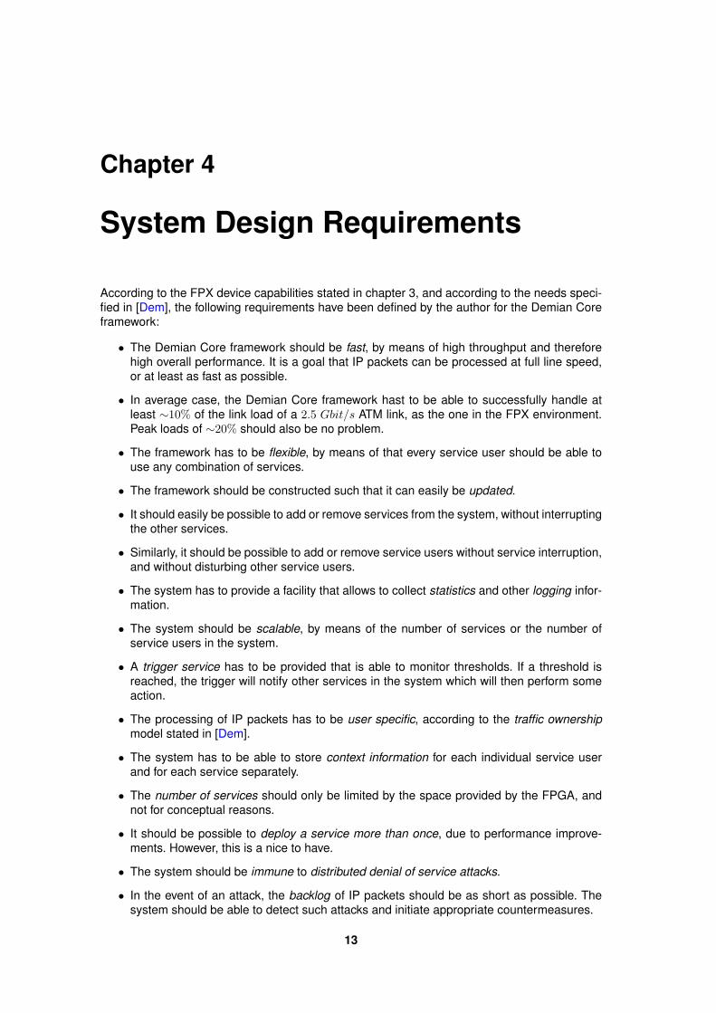
According to the FPX device capabilities stated in chapter 3, and according to the needs speci-fied in [Dem], the following requirements have been defined by the author for the Demian Coreframework:
• The Demian Core framework should be fast, by means of high throughput and thereforehigh overall performance. It is a goal that IP packets can be processed at full line speed,or at least as fast as possible.
• In average case, the Demian Core framework hast to be able to successfully handle atleast ∼10% of the link load of a 2.5 Gbit/s ATM link, as the one in the FPX environment.Peak loads of ∼20% should also be no problem.
• The framework has to be flexible, by means of that every service user should be able touse any combination of services.
• The framework should be constructed such that it can easily be updated.
• It should easily be possible to add or remove services from the system, without interruptingthe other services.
• Similarly, it should be possible to add or remove service users without service interruption,and without disturbing other service users.
• The system has to provide a facility that allows to collect statistics and other logging infor-mation.
• The system should be scalable, by means of the number of services or the number ofservice users in the system.
• A trigger service has to be provided that is able to monitor thresholds. If a threshold isreached, the trigger will notify other services in the system which will then perform someaction.
• The processing of IP packets has to be user specific, according to the traffic ownershipmodel stated in [Dem].
• The system has to be able to store context information for each individual service userand for each service separately.
• The number of services should only be limited by the space provided by the FPGA, andnot for conceptual reasons.
• It should be possible to deploy a service more than once, due to performance improve-ments. However, this is a nice to have.
• The system should be immune to distributed denial of service attacks.
• In the event of an attack, the backlog of IP packets should be as short as possible. Thesystem should be able to detect such attacks and initiate appropriate countermeasures.
13
14 System Design Requirements
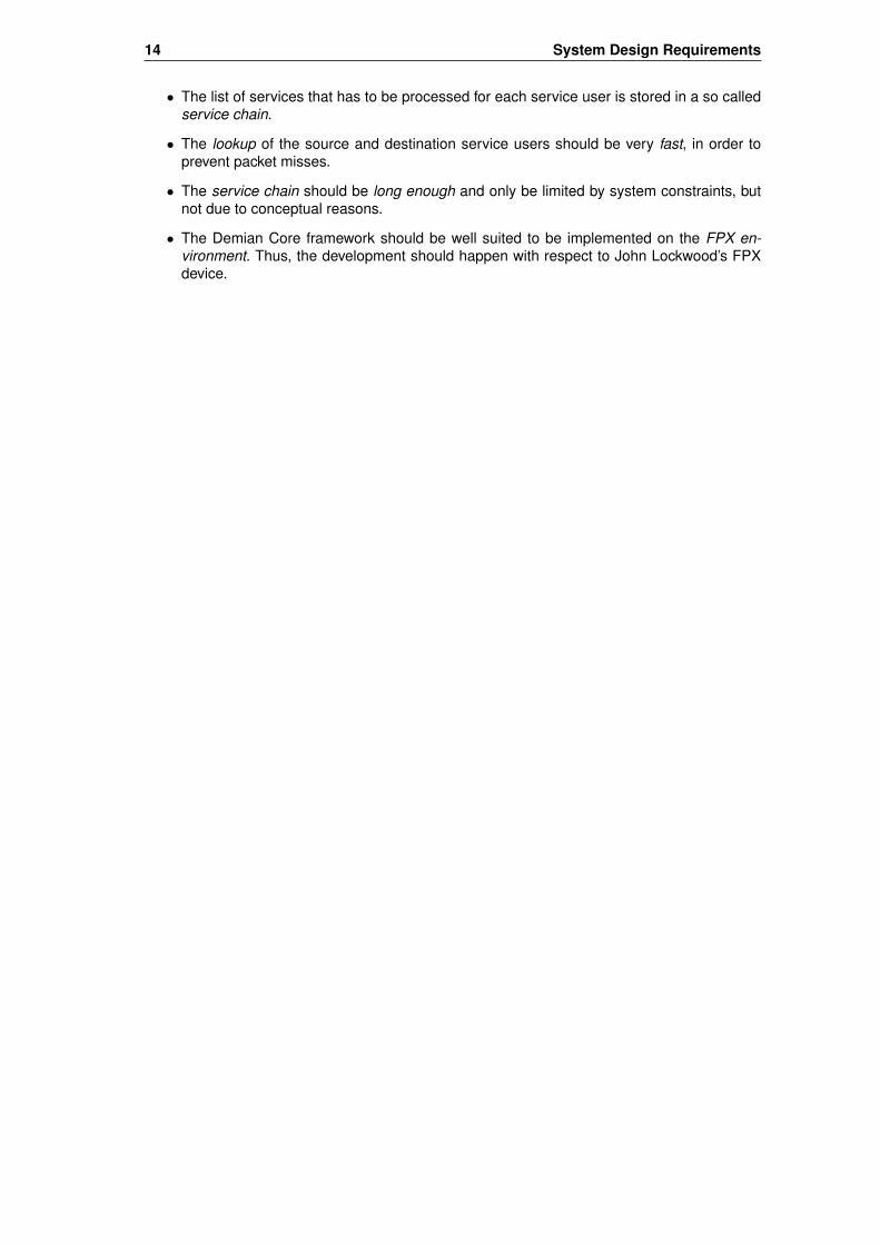
• The list of services that has to be processed for each service user is stored in a so calledservice chain.
• The lookup of the source and destination service users should be very fast, in order toprevent packet misses.
• The service chain should be long enough and only be limited by system constraints, butnot due to conceptual reasons.
• The Demian Core framework should be well suited to be implemented on the FPX en-vironment. Thus, the development should happen with respect to John Lockwood’s FPXdevice.

Chapter 5
System Design Description
This chapter describes the "Demian Core" framework that was developed during this thesis.The first section introduces basic definitions needed to understand the framework, followed bya description of the main flow of data and control information. Section 5.2 describes the frame-work in detail, followed by a summary of all flags and fields used in the system. Section 5.12explains the concept of triggers and their interaction with the services. Finally, the last sectionsummarizes design alternatives of frameworks that have been designed before.
5.1 System Design Overview
This section gives an overview of the framework depicted in figure 5.1, which should make iteasier to understand the framework description following in section 5.2. The first couple sectionsbriefly describe all important components and issues, whereas the last two sections describethe main data and control information flow.
5.1.1 Service User
From the legal point of view, a service user is a physical person or a company that owns anIP address or an entire range of IP addresses, and wants to use services provided by a TrafficControl Service Provider (TCSP), as explained in chapter 1. To be able to use services offeredby a TCSP, a service user has to register for the wanted services, e.g. by signing an agreementor a contract with the TCSP.
From the technical point of view, a service user is nothing but a range of IP addresses, whichis determined by the length of the netmask. This means that a service user can be an entire net-work or subnet of a company, such as 129.132.0.0/16 for the ETH network or 129.132.119.0/24 forthe ETH TIK subnet, or a single host, such as 129.132.119.132/32 for host tik2.ethz.ch. Note thataccording to the traffic ownership model described in [Dem], the TCSP distinguishes betweensource and destination IP addresses. This means that a service user is uniquely identified by a32 bit IP address, in combination with a 1 bit traffic direction flag.
Once an agreement or a contract has been signed, the TCSP will save the requested IP ad-dress or entire IP address range into the system’s User RAM (see section 5.1.8), accompaniedby a traffic direction flag, and in combination with a list of services (see section 5.1.5) that theservice user has registered for.
5.1.2 System Policy
If no service user could be found for a certain IP packet, the system may act in two differentways: Either, the IP packet can be forwarded straight to the IP wrapper (forwarding policy), orthe IP packet can be dropped (drop policy). According to [Dem], IP packets should only beforwarded to the Demian Core if they belong to at least one service user, and otherwise take therouter’s direct (fast) path. Therefore, let’s assume that the system’s policy is to drop IP packetsfor which no users could be found.
15
16 System Design Description
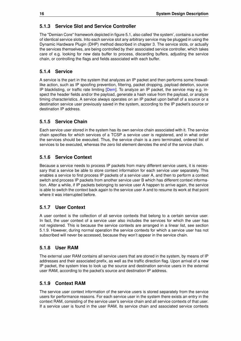
5.1.3 Service Slot and Service Controller
The "Demian Core" framework depicted in figure 5.1, also called ‘the system’, contains a numberof identical service slots. Into each service slot any arbitrary service may be plugged in using theDynamic Hardware Plugin (DHP) method described in chapter 3. The service slots, or actuallythe services themselves, are being controlled by their associated service controller, which takescare of e.g. looking for new data buffer to process, discarding buffers, adjusting the servicechain, or controlling the flags and fields associated with each buffer.
5.1.4 Service
A service is the part in the system that analyzes an IP packet and then performs some firewall-like action, such as IP spoofing prevention, filtering, packet dropping, payload deletion, sourceIP blacklisting, or traffic rate limiting [Dem]. To analyze an IP packet, the service may e.g. in-spect the header fields and/or the payload, generate a hash value from the payload, or analyzetiming characteristics. A service always operates on an IP packet upon behalf of a source or adestination service user previously saved in the system, according to the IP packet’s source ordestination IP address.
5.1.5 Service Chain
Each service user stored in the system has its own service chain associated with it. The servicechain specifies for which services of a TCSP a service user is registered, and in what orderthe services should be executed. Thus, the service chain is a zero terminated, ordered list ofservices to be executed, whereas the zero list element denotes the end of the service chain.
5.1.6 Service Context
Because a service needs to process IP packets from many different service users, it is neces-sary that a service be able to store context information for each service user separately. Thisenables a service to first process IP packets of a service user A, and then to perform a contextswitch and process IP packets from another service user B which has different context informa-tion. After a while, if IP packets belonging to service user A happen to arrive again, the serviceis able to switch the context back again to the service user A and to resume its work at that pointwhere it was interrupted before.
5.1.7 User Context
A user context is the collection of all service contexts that belong to a certain service user.In fact, the user context of a service user also includes the services for which the user hasnot registered. This is because the service contexts are arranged in a linear list, see section5.1.9. However, during normal operation the service contexts for which a service user has notsubscribed will never be accessed, because they won’t appear in the service chain.
5.1.8 User RAM
The external user RAM contains all service users that are stored in the system, by means of IPaddresses and their associated prefix, as well as the traffic direction flag. Upon arrival of a newIP packet, the system tries to look up the source and destination service users in the externaluser RAM, according to the packet’s source and destination IP address.
5.1.9 Context RAM
The service user context information of the service users is stored separately from the serviceusers for performance reasons. For each service user in the system there exists an entry in thecontext RAM, consisting of the service user’s service chain and all service contexts of that user.If a service user is found in the user RAM, its service chain and associated service contexts
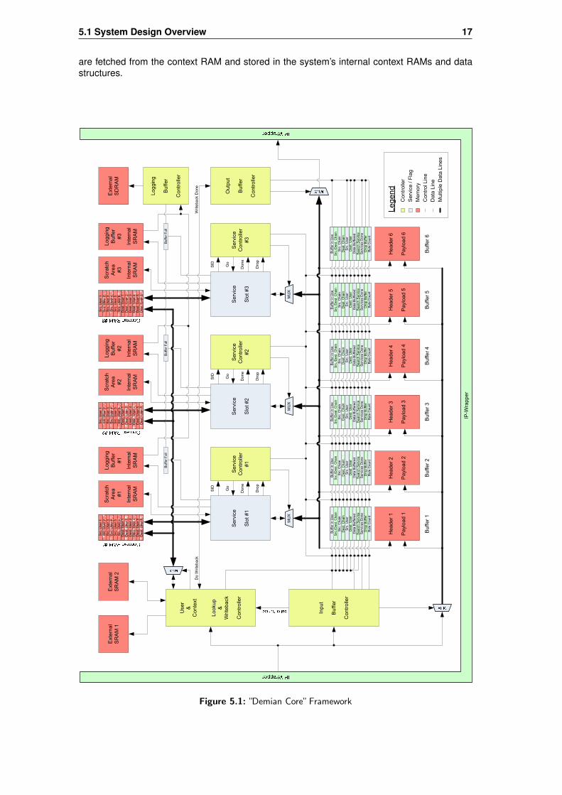
5.1 System Design Overview 17
are fetched from the context RAM and stored in the system’s internal context RAMs and datastructures.
External
SRAM 1
External
SRAM 2
User
&
Context
Lookup
&
Writeback
Controller
Input
Buffer
Controller
Output
Buffer
Controller
IP-Wrapper
MUX
Service
Slot #1
Service
Controller
#1
MUX
Service
Slot #2
Service
Controller
#2
MUX
Service
Slot #3
Service
Controller
#3
Go
Done
Drop
SID
Go
Done
Drop
SID
Go
Done
Drop
SID
Buffer 1
Header 1
Payload 1
Buffer 2
Header 2
Payload 2
Buffer 3
Header 3
Payload 3
Buffer 4
Header 4
Payload 4
Buffer 5
Header 5
Payload 5
Buffer 6
Header 6
Payload 6
Controller
Service / Flag
Legend
Memory
Src. User 1
Src. User 2
Src. User 3
Src. User 4
Src. User 5
Src. User 6
Dest. User 1
Dest. User 2
Dest. User 3
Dest. User 4
Dest. User 5
Dest. User 6
Scratch
Area
#1
Internal
SRAM
Logging
Buffer
#1
Internal
SRAM
Src. User 1
Src. User 2
Src. User 3
Src. User 4
Src. User 5
Src. User 6
Dest. User 1
Dest. User 2
Dest. User 3
Dest. User 4
Dest. User 5
Dest. User 6
Scratch
Area
#2
Internal
SRAM
Logging
Buffer
#2
Internal
SRAM
Src. User 1
Src. User 2
Src. User 3
Src. User 4
Src. User 5
Src. User 6
Dest. User 1
Dest. User 2
Dest. User 3
Dest. User 4
Dest. User 5
Dest. User 6
Scratch
Area
#3
Internal
SRAM
Logging
Buffer
#3
Internal
SRAM
External
SDRAM
Buffer Full
Buffer Full
Buffer Full
Logging
Buffer
Controller
Data Line
Multiple Data Lines
Control Line
Buffer in Use
Src./Dest. Chain
Src. Chain
Dest. Chain
Src. User
Dest. User
Search Service
Services Done
Drop Buffer
Data Buffered
Byte Count
Buffer in Use
Src./Dest. Chain
Src. Chain
Dest. Chain
Src. User
Dest. User
Search Service
Services Done
Drop Buffer
Data Buffered
Byte Count
Buffer in Use
Src./Dest. Chain
Src. Chain
Dest. Chain
Src. User
Dest. User
Search Service
Services Done
Drop Buffer
Data Buffered
Byte Count
Buffer in Use
Src./Dest. Chain
Src. Chain
Dest. Chain
Src. User
Dest. User
Search Service
Services Done
Drop Buffer
Data Buffered
Byte Count
Buffer in Use
Src./Dest. Chain
Src. Chain
Dest. Chain
Src. User
Dest. User
Search Service
Services Done
Drop Buffer
Data Buffered
Byte Count
Buffer in Use
Src./Dest. Chain
Src. Chain
Dest. Chain
Src. User
Dest. User
Search Service
Services Done
Drop Buffer
Data Buffered
Byte Count
Writeback Done
Do Writeback
Figure 5.1: ”Demian Core”Framework

18 System Design Description
5.1.10 Internal Context RAMs
Each service has an internal context RAM associated with it, which contains service contextsfrom all different users, but all of them are destined for this service. The service contexts of aservice user are retrieved from the external context RAM upon arrival of a new IP packet, anddistributed to all internal context RAMs, according to the service number. If no IP packet of aservice user is in the system anymore, the service contexts of that user will be written back tothe external context RAM. The internal context RAMs can be looked at as kind of second levelcaches: contexts are fetched from external RAM and stored close to where they are needed.
5.1.11 Data Buffer
Each data buffer in the system stores exactly one IP packet, which consists of both header andpayload. As long as an IP packet is in the system, it will always reside in the same initial buffer itwas assigned to when it entered the system. Then, many different services may act on a buffer,depending on the source and destination user’s service chains. If both service chains have beenprocessed, the buffer will be passed on to the IP wrapper again.
5.1.12 Data Flow
When a new IP packet arrives at the surrounding IP wrapper, it is passed on to the "DemianCore" framework, as depicted in figure 5.1. The Input Buffer Controller (IBC) will take care ofthe new IP packet and assign it a free buffer. Then, the IBC will write all arriving bytes of thisIP packet into that buffer, and finally again wait for the next IP packet to arrive. Should no newbuffer be available upon arrival of a new IP packet, the IBC will discard it. When an IP packet gotsuccessfully buffered, it will be processed by one or more services, according to the source anddestination service chains. While an IP packet is buffered in the system and being processed, itwill always remain in the same initial buffer. If the IP packet has been processed by all services,it will be forwarded by the Output Buffer Controller (OBC) again to the IP wrapper.
5.1.13 Context Information Flow
At the same time as a new IP packet is being buffered by the OBC, the Lookup & WritebackController (LWC) looks up the service users according to the IP packet’s source and destinationIP addresses. If one or both users are found, the LWC will fetch the concerning user contextsand write them into the internal context RAMs, as depicted in figure 5.1. From now on, the ser-vices have access to the service user’s context information of a buffer (IP packet) that they arecurrently processing. If the services are done and the IP packet leaves the Demian Core sys-tem again, the LWC will perform the context writeback upon order of the Output Buffer Controller(OBC).
5.2 Demian Core Framework Description
Whereas the last section gave an overview over the Demian Core framework, this section goesmore into the details and gives a thorough description about all controllers and additional com-ponents, such as logging mechanism and scratch area. The Demian Core framework is depictedin figure 5.1.
5.2.1 Input Buffer Controller (IBC)
The most important task of the IBC is to allocate a free buffer for an incoming IP packet, and towrite the arriving data (header and payload) into the buffer.
When the first word of a new IP packet arrives, the IBC chooses a free buffer according tothe "Buffer in Use" flags associated with each buffer. If a free buffer is found, the IBC immedi-ately allocates it by setting the "Buffer in Use" flag corresponding to that buffer. Then, the IBCcommunicates the "Buffer Number" of the just allocated buffer to the Lookup & Writeback Con-troller (LWC), because the LWC needs this information to update its internal table and the flags

5.2 Demian Core Framework Description 19
and field corresponding to the buffer currently being written, namely "Src./Dest. Chain", "Src.Chain", "Dest. Chain", "Src. User", "Dest. User", and "Search Service". The IBC state machineis shown in figure 5.2.
While the "Buffer in Use" flag is set and the "Data Buffered" flag is not set, the IBC continueswriting data words into the buffer, until the entire packet (header and payload) is buffered. Whilebuffering, the IBC will also update the "Byte Count" field associated with the buffer. If all wordshave successfully been buffered and the "Buffer is Use" flag is still set, the IBC will set the "DataBuffered" flag and wait for the next arriving IP packet to be buffered.
However, while the IBC is buffering data words, it is possible that either the LWC clears the"Buffer in Use" flag in case it was not able to find any service user, meaning that the IP packetshould be discarded, or that the SRV sets the "Data Buffered" flag, meaning that the payloadshould be deleted. If either or both of this happens, the IBC will immediately stop buffering anddiscard all arriving data words of this IP packet. Once all data words have been discarded, theIBC will wait for the next arriving IP packet to be buffered, and then again look for a free buffer.
If upon arrival of a new IP packet no buffer is available at all, the IBC discards the packetand waits for the next one. The IBC keeps track of how many packets arrived, how many ofthem it was able to buffer and how many it had to discard due to congestion or unknown serviceusers. These counters can be read using the FPGAs Control Cell Processor (CCP) mechanism,as described in section 3. Another possibility for the IBC to communicate statistical data to theouter world would be to use the same logging mechanism used for the services: data to belogged could be written into a special logging buffer assigned to the IBC (see section 5.2.7),from where it would later on be written into the external SDRAM. However, currently this loggingmechanism is only intended for the services, but could easily be expanded to other systemcomponents.
New IP packet & Buffer available
Init
Last Data WordNew IP packet &
No Buffer available
Fetch Last
- Buffer received Data Word
- Update "Byte Count"
- Set "Data Buffered" Flag
- Buffer received Data Word
- Update "Byte Count"
Fetch NextSkip
- Discard received Data Word
- Notify LWC: "Buffer Number" = invalid
if IP packet just arrived
Fetch First
- Initialize all Buffer Flags (set to Zero)
- Allocate Buffer by setting the "Buffer in
Use" Flag
- Buffer received Data Word
- Notify LWC: send "Buffer Number"
Idle
- Wait for new IP packet to arrive
"Buffer in Use" clear | "Data Buffered" set
Figure 5.2: ”Input Buffer Controller”State Diagram
5.2.2 Lookup & Writeback Controller (LWC)
The LWC performs three major tasks. First of all, it looks up the service users in the externalSRAM1 according to the source and destination IP addresses. Second, it fetches the servicechain and the context information from the external SRAM2 for all services belonging to a user,and writes the context information into the internal context RAMs associated with each service,according to the service. Third, if the context of a user is not needed anymore, the LWC writesit back into the external SRAM2.

20 System Design Description
Before the LWC can initiate the user lookups, it first needs to extract the source and desti-nation IP addresses from the arriving IP packet, as shown in figure 5.3. Immediately after thesource IP address is extracted, the LWC will perform the source service user lookup, followedlater on by the destination service user lookup, as described in the next section.
Init
Idle
- Wait for new IP packet to arrive
Skip IP Header Word 1
- Reset LWC internal Flags
- Skip IP Header Word 1 (Version, IHL,
TOS, Precedence Flags, Total Length)
Skip IP Header Word 2
- Skip IP Header Word 2 (Identification,
Fragment Offset, Fragment Flags)
Skip IP Header Word 3
- Skip IP Header Word 3 (TTL, Protocol,
Header Checksum)
Fetch Src. IP Address
- Remember Source IP Address
- Set LWC internal Flag "Src. IP Fetched"
Fetch Dest. IP Address
- Remember Destination IP Address
- Set LWC internal Flag "Dest. IP
Fetched"
Figure 5.3: ”Lookup & Writeback Controller”State Diagram: IP Fetch
Service User Lookup
When a new IP packet arrives, the LWC will first look up the ‘source service user’ in the externalSRAM1 according to the packet’s source IP address, followed by a lookup of the ‘destinationservice user’ according to the destination IP address.
In order to look up a source or a destination service user in the external SRAM1, the LWCneeds to search for the longest matching prefix of the source or destination IP address, respec-tively. This is done by using the "Tree Bitmap Algorithm", which is described in section 6.1 andin [FIP][Eat]. If a user lookup is successful, the algorithm returns a pointer into SRAM2, wherethe service chain and the service contexts for this service user are stored.
The LWC saves the retrieved service chain for the source and destination service users intothe "Src. Chain" and the "Dest. Chain" fields associated with a buffer, respectively. The LWC isable to identify the correct buffer and its associated flags and fields through the "Buffer Number"signal received from the IBC.
The LWC maintains an internal table (see table 5.1) in which it stores all the important in-formation concerning user and context handling, namely a "Reference Count", the IP addressstored in the IP packet, together with the retrieved prefix for a given user, whether it is a sourceor a destination IP address, and finally a pointer to the information in SRAM2 (service chain andservice contexts). Since each user context exists only once within the internal Context RAMs ata given time, the "Reference Count" tells the LWC how many buffers belong to the same serviceuser. The "IP address/prefix" field allows the LWC together with the "Src./Dest." field to check ifa service user already exists in the internal table. Finally, the "Pointer into Context RAM" allowsthe LWC to write a given context back to the external SRAM2 if the "Reference Count" reacheszero again.
If a lookup was successful, the LWC checks its internal table according to the "IP ad-dress/prefix" field and the "Src./Dest." flag for whether the just found user already exists in thetable, meaning that the context was already fetched before. If so, the only thing the LWC doesis to increment the "Reference Count" for this service user by 1. If the user does not yet existin the table, the LWC looks for a new free entry in the table, indicated by a "Reference Count"

5.2 Demian Core Framework Description 21
of zero, and saves the IP address, the prefix, whether it is a source or a destination IP address,and the pointer to the context of the just found user into the table. Then, the "Reference Count"is incremented by 1. There will always be an empty entry available in the internal table, sincethe table consists of twice as many entries as there are data buffers in the system – for eachbuffer, there are two entries available in the table, one for the source service user and one forthe destination service user.
Src./Dest. User Reference Src./ IP address/prefix Pointer intoCount Dest. Context RAM
Src. User 1 0 0Src. User 2 0 0Src. User 3 1 0 82.130.103.61/23 0x00000020Src. User 4 1 0 82.130.103.61/16 0x00000040Src. User 5 0 0Src. User 6 1 0 82.130.103.61/32 0x000002a0Dest. User 1 1 1 82.130.103.61/16 0x00000000Dest. User 2 0 1Dest. User 3 1 1 82.130.103.61/32 0x00000180Dest. User 4 0 1Dest. User 5 1 1 82.130.103.61/23 0x000000c0Dest. User 6 0 1
Table 5.1: Internal Table of the Lookup & Writeback Controller (LWC)
Source service users are always stored within the lower half of the internal table, whereasdestination service users are stored within the upper half of the table. If a user was found inthe external SRAM1 and the information got successfully stored in the internal table and theflags and fields, from now on the other components within the system will refer to this user onlyby its line number within the table half, e.g. indicated by "Src. User 3" or "Dest. User 5". TheLWC stores this information into the buffer’s "Src. User" and "Dest. User" fields, which allowsthe Services (SRV), the Service Controllers (SRC), and the Output Buffer Controller (OBC) lateron to reference a user.
If no service user could be found, the LWC can do two things, depending on the system’spolicy: either, the just buffered IP packet is discarded right away (drop policy), or it is passedthrough the system without being processed by any service (forwarding policy). If the system’spolicy is to throw such packets away, the LWC will clear the "Buffer in Use" flag, which tellsthe IOB to immediately stop buffering of the current IP packet and marks the buffer as freeagain. This will cause its content to be overwritten by future IP packets. On the other hand, if thesystem’s policy is to pass such packets through the system, the LWC leaves the buffer allocatedand additionally sets the "Services Done" flag. This will cause all services to be skipped, andtells the Output Buffer Controller (OBC) to process the buffer and thus to pass its content straighton to the IP wrapper.
However, for this design and the performance analysis in chapter 7, let’s assume that thesystem’s policy is to drop IP packets for which no service user was found, because such IPpackets should actually not have been forwarded to the Demian Core. Instead, they should havetaken the direct path (fast path) through the router [Dem]. Figure 5.4 shows the user lookup statediagram.
Once the service users have successfully been looked up an the concerning contexts havebeen fetched (see next section), the LWC will set the buffer’s "Search Service" flag. This tells allservice controllers (SRC) that this buffer is ready to be processed and is looking for a service.Note that it is possible that a buffer is being processed by the services, even though the IBCis not yet done with the data buffering. This has the advantage that fast services that do notexamine the header and/or the payload can do their work, which might increase overall systemthroughput. On the other hand, if a slow service needs to inspect the header and/or the payloadand the data buffering is still in process ("Data Buffered" flag not yet set), the service will haveto wait until the IBC sets the "Data Buffered" flag.

22 System Design Description
Init
"Src. IP Fetched"
Idle
- Wait for Src. IP Address to be fetched
dataen = 1
Lookup Dest. User
- Clear internal "Dest. IP Fetched" Flag
- If Dest. Service User found:
- Set LWC internal "Dest. User Found"
Flag
- Save Dest. User in internal Table and
in "Dest. User" Buffer Flag
"Dest. IP Found"
Lookup Src. User
- Clear internal "Src. IP Fetched" Flag
- If Src. Service User found:
- Set LWC internal "Src. User Found"
Flag
- Save Src. User in internal Table and in
"Src. User" Buffer Flag
Src. User found &
Dest. User not found
Src. User not found &
Dest. User not foundDepending on the System’s Policy:
a) Forward: Set "Search Service" Flag
b) Drop: Clear "Buffer in Use" Flag
No User Found
- Wait until "Src. Context Fetched" set
- Set the "Search Service" Flag
- Clear the "Src. Context Fetched" Flag
Only Src. User Found
"Src. IP Fetched" & [ "Dest. User Found" |
("Src. User Found" & "Dest. User Found") ]
Figure 5.4: ”Lookup & Writeback Controller”State Diagram: User Lookup
Service Chain and Context Fetch
If a service user lookup was successful for a given user, a pointer into the context RAM (externalSRAM2) is returned, which allows the state machine depicted in figure 5.5 to access the servicechain and the user context information. Using this pointer, the LWC will fetch the service chainin any case, which will be stored in the concerning buffer’s "Src. Chain" or "Dest. Chain" field,depending of what kind of user is is.
If the context for this user is not currently stored in the internal context SRAMs, the LWCwill also fetch the user context from the external SRAM2, using the pointer. A context of a userconsists of many ‘service contexts’, one for each service slot in the system. Since the servicechain and the service contexts of a user are contiguously saved in the SRAM2, the LWC is ableto fetch all of them by incrementing the pointer. After fetching the context of a service user, theLWC stores the service contexts of that user distributedly into all internal context RAMs, accord-ing to the service. Since each context RAM is associated with its service slot and thus with itsservice, a context RAM contains only service contexts for this service, but from different users.Because the service contexts in the external SRAM2 are stored contiguously, they could beseen as some kind of ‘vertically partitionized’. Therefore, the way of saving the service contextsdistributedly in the internal context RAMs could be called ‘horizontally partitionized’.
Since both the LWC and the service (SRV) associated with a given service context need toread and/or write the internal context RAM, the access to it has somehow to be controlled. Thereare two ways how this can be achieved: First of all, if the internal context RAMs are dual portRAMs, it is possible that both the LWC and the SRV access the context RAM at the same time,since they won’t access the service context of the same user at the same time. This is becauseas long as a service context is already cached in the internal SRAM and potentially being usedby the service, the LWC will not fetch it again. The same is true for the writeback. And a SRVwill never access the service context of a user that has not yet been fetched. If no dual portRAM is available, the access has to be controlled with additional control lines between the LWCand the SRV. In this case, the LWC has always priority over the SRV, since context fetch andwriteback are time critical operations. If the LWC wants to access the context RAM, it notifiesthe corresponding SRV. This means that the SRV has to wait until the LWC is done. However,for this design and the performance analysis in chapter 7, let’s assume that the internal contextSRAMs really are dual port RAMs, and therefore that a SRV and the LWC may access theconcerning internal context RAM simultaneously.

5.2 Demian Core Framework Description 23
Init
"Src. User Found" not true &
"Dest. User Found" not true
"Dest. User Found" &
"Src. User Found" not set
Idle
- Wait until one of the LWC internal Flags
"Src. User Found" or "Dest. User Found"
is set
Fetch Src. Service Chain
- Write Src. Service Chain into Buffer
Field "Src. Chain"
Fetch Dest. Service Chain
- Write Dest. Service Chain into Buffer
Field "Dest. Chain"
- Set "Src. Context Fetched"
Fetch Src. Service Context #1
- Write Src. Service Context #1 into the
internal Context SRAM of Service #1,
Position according to the internal Table
Fetch Dest. Service Context #1
- Write Dest. Service Context #1 into the
internal Context SRAM of Service #1,
Position according to the internal Table
Fetch Src. Service Context #2
- Write Src. Service Context #2 into the
internal Context SRAM of Service #2,
Position according to the internal Table
Fetch Src. Service Context #n
- Write Src. Service Context #n into the
internal Context SRAM of Service #n,
Position according to the internal Table
- Set "Src. Context Fetched"
Fetch Dest. Service Context #2
- Write Dest. Service Context #2 into the
internal Context SRAM of Service #2,
Position according to the internal Table
Fetch Dest. Service Context #n
- Write Dest. Service Context #n into the
internal Context SRAM of Service #n,
Position according to the internal Table
- Set "Dest. Context Fetched"
- Set "Search Service" Flag
Figure 5.5: ”Lookup & Writeback Controller”State Diagram: Context Fetch
Context Writeback
If a buffer has been processed by various services and is now ready to be forwarded to the IPwrapper again, indicated by the "Services Done" flag, the Output Buffer Controller (OBC) willperform the data passing to the IP wrapper. Furthermore, it notifies the LWC about which sourceand destination contexts are not needed anymore and might eventually be written back to theexternal SRAM2. The OBC gains this information from the "Src. User" and "Dest. User" fieldsassociated with the concerning buffer. The LWC looks up the service users in its internal tableand decrements the "Reference Count" by one. If the "Reference Count" of a certain user dropsback to zero, the LWC will write the context for that user back into the SRAM2 using the pointerstored in the internal table. Since the context of a user is distributed over all context RAMs,the LWC collects all service contexts from all internal context RAMs and writes them back intothe SRAM2. Concerning simultaneous context RAM accesses by the LWC and the SRV, thesame restrictions apply as described in the "Context Fetch" section. If the context writeback isfinished, the LWC will notify the OBC about that. The context writeback state machine is shownin figure 5.6.

24 System Design Description
Coordination between Context Fetch and Context Writeback
Because the external context RAM needs possibly to be read and written by the LWC at thesame time, the access to it has to be controlled. The solution preferred in this design is to alloweach of the context fetch and context writeback operations to exclusively access the externalcontext RAM using the fixed timing scheme depicted in figure 5.7. As you can see, there is afixed time interval to fetch the service chain and the service contexts, and to write back theservice contexts. For example, the source service chain is fetched in cycle 14, followed by fourcontext fetch and four context writeback operations. Then, the destination service chain can befetched in cycle 23, and so on. The timing issues are explained in detail in chapter 7.2.
Init
"Do Writeback" not yet set |
No valid User
Idle
- Wait for the OBC to send the
"Do Writeback" signal
Writeback Src. Context #1
- Get the Src. Service Context #1 from the
internal Context SRAM of Service #1
and write it back into the external
Context SRAM. Memory Positions
according to the Internal Table
Writeback Src. Context #2
- Get the Src. Service Context #2 from the
internal Context SRAM of Service #2
and write it back into the external
Context SRAM. Memory Positions
according to the Internal Table
Writeback Dest. Context #1
- Get the Dest. Service Context #1 from
the internal Context SRAM of Service #1
and write it back into the external
Context SRAM. Memory Positions
according to the Internal Table
Writeback Dest. Context #2
- Get the Dest. Service Context #2 from
the internal Context SRAM of Service #2
and write it back into the external
Context SRAM. Memory Positions
according to the Internal Table
"Do Writeback" &
"Src. User" not valid &
"Dest. User" valid
Writeback Src. Context #3
- Get the Src. Service Context #3 from the
internal Context SRAM of Service #3
and write it back into the external
Context SRAM. Memory Positions
according to the Internal Table
- If "Dest. User" not valid, send "Writeback
Done" signal to the OBC
Writeback Dest. Context #3
- Get the Dest. Service Context #3 from
the internal Context SRAM of Service #3
and write it back into the external
Context SRAM. Memory Positions
according to the Internal Table
- Send "Writeback Done" signal to the
OBC
Figure 5.6: ”Lookup & Writeback Controller”State Diagram: Context Writeback
5.2.3 IBC and LWC Interaction
Figure 5.7 shows a sequence diagram that explains the interaction between the IBC, the LWC,and the external service user and context SRAMs. In cycle 2 the IBC notifies the LWC about thebuffer number. The LWC has to wait until the source IP address is received in cycle 4. Then, it willstart the source user lookup in cycle 5, which will last no more than 9 cycles (see chapter 7.2).In cycle 14 the LWC will initiate the destination service user lookup. Also in cycle 14 it will lookup the source service chain. In the next cycle the LWC will look up the service contexts of thesource user if they have not been fetched before. Cycles 19 through 22 can be used to writecontext information back to the external SRAM2. In cycle 23 the LWC will initiate the sourceservice user lookup of the next IP packet, according to the source IP address fetched one cyclebefore. Also in cycle 23 the destination service chain is fetched, followed by destination servicecontext fetches until cycle 27. Cycles 28 until 31 can be used to write context information backto the external SRAM2. Finally, in cycle 32 the lookup for the destination service user of the next

5.2 Demian Core Framework Description 25
IP packet begins, according to the destination IP address fetched in cycle 23. In cycle 28 theLWC will eventually clear the "Buffer in Use" flag if no user was found for the first IP packet. Thetiming issues are explained in detail in chapter 7.2.
Header 1
Header 2
Header 3
Src. IP Address
Dest. IP Address
Buffer Number
Idle / Data Word 1
Idle / Data Word 2
Idle / Data Word 3
Idle / Data Word 4
Idle / Data Word 5
Idle / Data Word 6
Idle / Data Word 7
Idle / Data Word 8
Idle / Data Word 9
Idle / Data Word 10
Idle / Data Word 11
Idle / Data Word 12
Header 1
Header 2
Header 3
Src. IP Address
Dest. IP Address
Idle / Data Word 1
Idle / Data Word 2
Idle / Data Word 3
Idle / Data Word 4
Idle / Data Word 5
Idle / Data Word 6
Idle / Data Word 7
Idle / Data Word 8
IBC LWC SRAM1 SRAM2
Idle / Data Word 13
Buffer Number
Users (not) Found
Src. User Service Chain Lookup
First Src. User Lookup
First Dest. User Lookup
First Src. User Lookup
First Dest. User Lookup
Idle / Data Word 9
1
2
3
4
5
6
7
8
9
10
11
12
13
14
15
16
17
18
19
20
21
22
23
24
25
26
27
28
29
30
31
32
Cycle
Last Src. User Lookup
First Src. User Context Lookup
Last Src. User Context Lookup
Last Dest. User Lookup
Dest. User Service Chain Lookup
First Dest. User Context Lookup
Last Dest. User Context Lookup
Last Src. User Lookup
Src. User Service Chain Lookup
Set Flags
Timeslot for Src. User
Context Writebacks
Timeslot for Dest. User
Context Writebacks
Figure 5.7: Sequence Diagram: IBC and LWC Interaction

26 System Design Description
5.2.4 Service (SRV) and Service Controller (SRC)
Basically the system contains a number of identical service slots, as described in section 5.1.3.Into each service slot any arbitrary service may be loaded, using the Dynamic Hardware Plugin(DHP) functionality described in chapter 3. A service (SRV) registers itself with the correspond-ing service controller (SRC) in that it notifies the SRC about its unique service id ("SID").
If a SRV is idle, that means no buffer is currently being processed, its associated SRC looksfor buffers which have the "Buffer in Use" flag and the "Search Service" flag set. The "SearchService" flag indicates that a buffer wants to be processed by a service. The "Src./Dest. Chain"indicates whether the "Src. Chain" field of the ‘source service user’ or the "Dest. Chain" field ofthe ‘destination service user’ should be used to determine the next service (NSR) to be called.Both of these fields contain an ordered list of services (service chain) that have to be called,whereas the most left list element within the service chain indicates the next service (NSR) tobe called. Therefore, the SRC has to compare the NSR field with the service id (SID) numberof its SRV, and if it matches, then this buffer will be chosen for processing. The SRC will thenclear the "Search Service" flag, which means that this buffer is being processed, and then startthe SRV by sending it the "Go" command.
Init
No "Go" yet
Go
Done, new "Go"
Service in Progress
- Service does ist Work:
- Read/Write the Service Context
- Read/Write the Buffer Flags
- Read/Write the Buffer
- Read/Write the Scratch SRAM
- Write the Logging Buffer
Idle
- Wait for Service Controller (SRC) to
send the "Go" Signal
Figure 5.8: ”Service”State Diagram
While the SRV runs, the SRC will determine the next service (NSR) to be called by modifyingthe "Src./Dest. Chain" flag, the "Src. Chain" field, and the "Dest. Chain" field the following way:If the "Src./Dest. Chain" flag is currently cleared, this means that right now the services ofthe ‘source service user’ are being processed. Therefore, the SRC will drop the next service(NSR) field within the "Src. Chain" field and shift the remaining fields to the left, so that the listelement that was the second one from the left in the list before indicates now the next service(NSR) to be called. If it happens that the NSR is zero after the shift, this means that all servicesfor the ‘source service user’ have been processed, and that the next service to be called is a‘destination service user’ service. Therefore, the SRC sets the "Src./Dest. Chain" flag, whichmeans that from now on the "Dest. Chain" field will be used instead of the "Src. Chain" field.The next service (NSR) to be called is therefore indicated by the most left list element of the"Dest. Chain" field. If it happens that this field is also zero, then no more services will have tobe called after this service. If the "Src./Dest. Chain" flag was already set when the SRC wantedto determine the next service (NSR) for the ‘source service user’, then the "Dest. Chain" fieldis shifted to the left instead of the "Src. Chain" field. If it happens that the most left field ofthe "Dest. Chain" field is zero after the shift, then this means that this is the last service to beprocessed.

5.2 Demian Core Framework Description 27
Init
No Buffer found
"Buffer in Use" &
"Search Service" &
Next Service (NSR) = Service ID (SID)
Idle
- Wait and look for Buffers that need to be
processed by this Service
Start Service
- Clear "Search Service" Flag
- Set "Go" Signal
- Determine Next Service (NSR) to call by
modifying "Src./Dest. Chain", "Src.
Chain", and "Dest. Chain"
Service not yet done
Wait for Service
- Wait until the Service is done
- If the Service is done:
- If Drop, set the "Drop" and the
"Services Done" Flags
- Otherwise, if there is a Next Service to
call, set the "Search Service" Flag
- Otherwise, if there are no more
Services to call, set the "Services
Done" Flag
Figure 5.9: ”Service Controller”State Diagram
While the SRV processes the buffer, it probably needs to access the context informationspecific to this buffer. Context information can be read or written by the service at any time1,e.g. to read or update counters or service specific flags. To access the context information ofthe correct service user, the service uses the "Src. User" or the "Dest. User" fields as an indexinto the context RAM, depending whether the service runs on behalf of a source or a destinationuser. The service also has exclusive access to a service specific scratch RAM and a loggingRAM, explained in section 5.2.6 and section 5.2.7, respectively.
If the service needs to access the header or the payload, it first has to make sure that the"Data Buffered" flag is set, since it is possible that the service was launched before the IBC hascompleted data buffering. If the flag is not yet set, the service will have to wait with the accessuntil the IBC sets this flag. However, another possibility is to access the buffer anyway, using the"Byte Count" flag, which indicates how many bytes already have been buffered and thereforeare valid. If the IP packet is large and only the first few bytes need to be inspected, this accessmethod might speed things up. If the SRV comes to the conclusion that for some reason thepayload of the IP packet should be cut or dropped, it self may set the "Data Buffered" flag andset the "Byte Count" to a new value. Of course, the new "Byte Count" value has to be less orequal to the number of bytes buffered so far. If the SRV set the "Data Buffered" flag, this willprevent the IBC from further data buffering.
When the service is done, it will notify the SRC using the "Done" signal. Additionally, if theservice comes to the conclusion that the buffer should be dropped, it will notify the SRC usingthe "Drop" signal. In this case, the SRC will set the "Drop" flag and the "Services Done" flag,which will instruct the OBC to discard the buffer but nevertheless perform the context writeback.
If the service is done and the buffer should not be discarded, the SRC can do two things: Ifthere are more services to call, according to the "Src./Dest. Chain", the "Src. Chain", and the"Dest. Chain" flags, it will set the "Search Service" flag again. This will cause the other servicecontrollers to include this buffer in their search for new buffers to be processed. If the mentionedflags and fields indicate that no more services are to be called, the SRC will set the "ServicesDone" flag, which tells the OBC that this buffer can be forwarded to the IP wrapper and thecontexts should eventually be written back.
1Supposed that the context RAM is a dual port RAM, see section 5.2.2 (Context Fetch) for restrictions

28 System Design Description
5.2.5 Output Buffer Controller (OBC)
The tasks of the Output Buffer Controller (OBC) are to pass buffers that have been processedon to the IP wrapper, and to commence the context writebacks.
The OBC looks for buffers that have the "Buffer in Use" flag and the "Services Done" flagset, which indicates that the buffers are ready to be passed on to the IP wrapper. Furthermore,it is also necessary that the "Data Buffered" flag be set, since it is possible that all services havecompleted their tasks and that the IBC is still buffering. Depending on the system’s policy it isalso possible that a buffer has not been processed by any service (forwarding policy), so thatit is likely to happen that the IBC is still buffering. If a buffer is found that has the three flagsset, it is chosen. If the "Drop" flag is not set, it will be forwarded to the IP wrapper. In any casethe OBC will initiate the context writeback for the involved context(s). For this purpose, the OBCwill notify the LWC by setting the "Do Writeback" signal, and also forward the "Src. User" andthe "Dest. User" fields. The LWC will decrement the "Reference Count" for this service user inits internal table and perform the writeback if the "Reference Count" reaches zero again. Oncethe writebacks have been performed, the LWC will notify the OBC by setting the "WritebackDone" signal. If the "Drop" flag is set, the buffer will not be forwarded to the IP wrapper, but thecontext writeback will still be performed. Once the buffer has been successfully forwarded to theIP wrapper and the notification about the successful context writeback has been received fromthe LWC, the OBC will clear the "Buffer in Use" flag, which makes the buffer available again.
Init
Buffer Found
("Buffer in Use", "Services Done", and
"Data Buffered" Flags are all set) &
Drop Flag not set
"Byte Count" = 1
Idle
- Wait and look for Buffers that need to be
forwarded to the IP Wrapper ("Buffer in
Use", "Services Done", and "Data
Buffered" Flags need to be set
Forward Next
- Forward next Word in the Buffer to the IP
Wrapper, decrement "Byte Count"
Wait
- Wait until the LWC sets the "Writeback
Done" Signal
Forward Last
- Forward last Word in the Buffer to the IP
Wrapper, decrement "Byte Count"
- Check "Writeback Done" Signal
Forward First
- Forward first Word in the Buffer to the IP
Wrapper, decrement "Byte Count"
- If "Src. User" or "Dest. User" Fields valid:
- Notify LWC: Send valid "Src. User"
and "Dest. User" Fields
- Set Signal "Do Writeback"
"Src. User" | "Dest. User" valid
&
"Writeback Done" not yet
"Byte Count" > 1
Wait
- If "Src. User" or "Dest. User" fields valid:
- Notify LWC: send valid "Src. User"
and "Dest. User" fields
- Set signal "Do Writeback"
- Wait until the LWC sets the "Writeback
Done" Signal
"Writeback Done" &
Buffer Found
"Writeback Done" &
Buffer not Found
No Buffer
available to
be forwarded
Buffer Found &
Drop Flag set
Figure 5.10: ”Output Buffer Controller”State Diagram
As you can see from figure 5.10, the OBC will wait until the LWC has performed the write-back operation and thus sets the "Writeback Done" signal. If an IP packet has to be dropped,this waiting may appear a little bit inefficient, but since the LWC uses the fixed time scheduledepicted in figure 5.7 that also depends on the context fetch operation, it does not matter inmost cases. Only if the IP packet has to be dropped and the LWC really has to perform a write-

5.2 Demian Core Framework Description 29
back instead of only decrementing the "Reference Count" field in the internal table, this mightbecome a performance issue, which is also discussed in chapter 7.
5.2.6 Scratch Area
Each service has its own internal SRAM associated with it, which may be used by the serviceas scratch area. The service is free to use this RAM for whatever it wants. For instance, theservice could use it to save general information that is not only specific to a certain serviceuser, and therefore could not be saved within the user’s context. For example, the service couldcount how many buffers it processed so far, and how many of them it discarded. Another ap-plication could for example be to use the scratch area as a memory for signatures or strings tobe matched. Since the scratch area RAM can easily be read and written by the FPGAs ControlCell Processor (CCP) facility, it would be easy to update the service with new signatures to bematched. Another interesting application could be to introduce a new global facility that all SRVwould have to support, such as a general service enable/disable mechanism. This could beachieved by implementing a service enable/disable flag in the scratch area, wich can be set orreset using the CCP. For instance, this would allow the TCSP to enable or disable a certain SRVfor all service users in one fell swoop, e.g. if problems with a SRV arose. Furthermore, a servicecould for instance be instructed by another flag in the scratch area to drop all packets for thetime being, e.g. if a SRV causes trouble and should therefore block all traffic. This would be theeasier way of globally blocking a service instead of modifying all concerned service users. Thismethod could also be used to implement global triggers, as described in section 5.4.1.
5.2.7 Logging Buffer Controller (LBC)
If a service needs to write any log data, it will write it into the logging buffer associated with eachservice. For example, a service might want to write a log entry if a certain threshold has beenreached, or if an attack has been detected. If the logging buffer is full, the service will set the"Buffer Full" flag. This will cause the Logging Buffer Controller (LBC) to read the buffer and towrite its contents to the external SDRAM. If this is done, the LBC will clear the "Buffer Full" flag,so that the service will be able to write more log entries. The external SDRAM can easily beaccessed with the FPGAs Control Cell Processor (CCP) facility, which allows one to retrieve thelog messages from the FPGA.
Init
"Buffer Full" not set
"Buffer Full"
Idle
- Wait and look for Logging Buffers that
need to be written into External SDRAM
Export Last
- Write last Log Word into External
SDRAM
- Clear the "Buffer Full" Flag
Export
- Write Log Word into External SDRAM Remaining Bytes > 1
Remaining Bytes = 1
Figure 5.11: ”Logging Buffer Controller”State Diagram
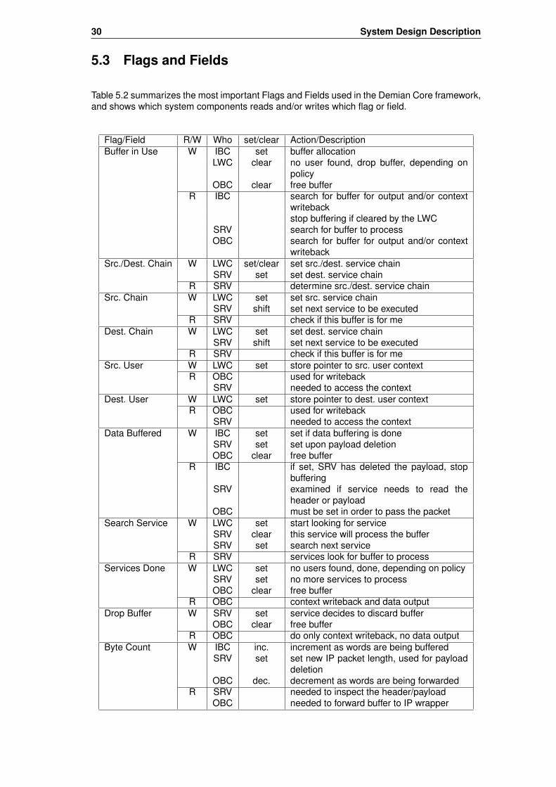
30 System Design Description
5.3 Flags and Fields
Table 5.2 summarizes the most important Flags and Fields used in the Demian Core framework,and shows which system components reads and/or writes which flag or field.
Flag/Field R/W Who set/clear Action/DescriptionBuffer in Use W IBC set buffer allocation
LWC clear no user found, drop buffer, depending onpolicy
OBC clear free bufferR IBC search for buffer for output and/or context
writebackstop buffering if cleared by the LWC
SRV search for buffer to processOBC search for buffer for output and/or context
writebackSrc./Dest. Chain W LWC set/clear set src./dest. service chain
SRV set set dest. service chainR SRV determine src./dest. service chain
Src. Chain W LWC set set src. service chainSRV shift set next service to be executed
R SRV check if this buffer is for meDest. Chain W LWC set set dest. service chain
SRV shift set next service to be executedR SRV check if this buffer is for me
Src. User W LWC set store pointer to src. user contextR OBC used for writeback
SRV needed to access the contextDest. User W LWC set store pointer to dest. user context
R OBC used for writebackSRV needed to access the context
Data Buffered W IBC set set if data buffering is doneSRV set set upon payload deletionOBC clear free buffer
R IBC if set, SRV has deleted the payload, stopbuffering
SRV examined if service needs to read theheader or payload
OBC must be set in order to pass the packetSearch Service W LWC set start looking for service
SRV clear this service will process the bufferSRV set search next service
R SRV services look for buffer to processServices Done W LWC set no users found, done, depending on policy
SRV set no more services to processOBC clear free buffer
R OBC context writeback and data outputDrop Buffer W SRV set service decides to discard buffer
OBC clear free bufferR OBC do only context writeback, no data output
Byte Count W IBC inc. increment as words are being bufferedSRV set set new IP packet length, used for payload
deletionOBC dec. decrement as words are being forwarded
R SRV needed to inspect the header/payloadOBC needed to forward buffer to IP wrapper

5.4 Trigger and Service Interaction 31
Flag/Field R/W Who set/clear Action/DescriptionBuffer Full W SRV set logging buffer is full
W LBC clear logging buffer is empty againR LBC check if buffer if fullR SRV check if buffer can be written
Table 5.2: Description of which component reads and/or writes a flag/field
5.4 Trigger and Service Interaction
This section describes the logical idea behind triggers, how they work, how they interact withthe services, and how they are implemented in the Demian Core framework.
5.4.1 Trigger Description
By definition, a trigger is a kind of a special service that observes incoming IP packets, andif a certain condition is met, it will notify (→ trigger) some other service. The idea is that e.g.during an attack, triggers can automatically activate predefined services [Dem]. For instance, atrigger could monitor the packet arrival rate, and if a certain threshold is reached, a predefinedservice that was inactive until now is notified and thus activated. Some time later, if the packetarrival rate falls below the threshold again, the service will be notified again and thus inactiveagain. There exist two different kind of triggers – per user triggers and global triggers – whichare explained in the subsequent paragraphs.
Per User Trigger
Per user triggers are always associated with a certain service user and therefore monitor onlythe traffic that is destined for this service user. Consequently, and due to the traffic ownershipprinciple described in [Dem], they may only notify services that also belong to this same serviceuser. Figure 5.12 shows the service chains of three different service users. All users have atrigger service in their chain, which monitors the traffic and eventually will notify a service withintheir chain.
S2 S3S1T1
S1 S2 S3
S1 S2 S3T
T1
T1
IP Wrapper
a) per user Trigger
a) per user Trigger
a) per user Trigger
b) global Trigger
User #1
User #2
User #3
Figure 5.12: Trigger and Services: a) per user Trigger b) global Trigger
Global Trigger
As you can see in figure 5.12, global triggers are not associated with a certain service user anymore. Instead, they monitor the common incoming traffic, and if a certain condition is met, aservice is notified. However, this notification will not only affect the service of one single serviceuser, but all service users having this service in their service chain and therefore are using thisservice.
This kind of trigger is actually against the traffic ownership model described in [Dem], be-cause it affects the traffic of many service users. However, it some special cases it might anyway
32 System Design Description
be useful and legitimate to use global triggers, as described in section 5.2.6. For example, if anattack is detected by a global trigger service, and hence a service is notified that will block theconcerned traffic, this might be desired or even wanted if both all affected service users andthe TCSP agreed upon such a behavior in advance. Therefore the Demian Core frameworksupports not only the implementation of per user triggers, but also the implementation of globaltriggers – but whether or not global triggers will actually be implemented and used in the DemianCore framework is an other issue not discussed here.
5.4.2 Trigger Implementation
This section presents how per user triggers are implemented in the Demian Core framework.Furthermore, it points out how global triggers could be implemented, though according to [Dem]they are not supposed to be used.
Per User Trigger
As the name indicates, a per user trigger is always specific to a certain service user. Therefore,all information concerning a per user trigger, such as different thresholds, has to be storedsomewhere in the service user’s context. The Demian Core framework allows per user triggersto be implemented in two different ways:
Trigger and Service separated: This is the trigger model according to figure 5.12a), wherea trigger is just a kind of a special service. It does not conduct any action with an IP packet,but only monitors the traffic and observes the trigger condition. If the trigger condition is met,a predefined service is notified. For a trigger service to be able to notify an other service, it isnecessary that a trigger be aware of the other services in the concerned service chain.
Because the Demian Core framework as is does actually not allow direct communicationbetween the services, it is necessary to introduce a new message passing facility that allows atrigger to notify a service. This can be done in two different ways:
First of all, each data buffer could be extended by a new "Trigger" field, similar to the "Src.Chain" or "Dest. Chain" fields, which contains an entry for each service that will be set by atrigger if it needs to notify a service. On the oder hand, all future services to be processed willhave to check the "Trigger" field in order to find out whether they are being triggered. This allowsa kind of a one way communication from a trigger to a service, or possibly multiple services atonce.
The second method is to reserve a special area in the data buffer RAM, for instance right atthe beginning or at the very end of the data buffer, which will be written by a trigger and read bythe services. For each service in the system there will be a designated trigger area in the databuffer RAM that contains information whether a trigger ‘fired an event’, and possibly some morestatus information.
Since in this trigger implementation a trigger is nothing but a kind of a special service, ithas access to its service context information in its associated service context RAM, where it willstore trigger information, such as thresholds. Both of these trigger notification methods keep thesystem flexible and even allow a trigger to notify multiple services at once by setting some bitsin the "Trigger" field or in the "Trigger Area", respectively, However, because each service needsto check the "Trigger" field or the "Trigger Area", this introduces a communication overhead thatslows down the system.
Trigger and Service combined: If a trigger condition is relevant for only one service withinthe service chain – and probably in most applications this will be the case – there is actuallyno reason why a trigger and its corresponding service should be separated. Actually, it is muchfaster and easier to combine them in one service, as depicted in figure 5.13. This also meansthat the trigger condition will be saved in the service context of the concerned service. In con-trast to the separated trigger model introduced before, this combined trigger model has theadvantage that trigger notification is a service internal issue and no notification between twoservices is necessary, which simplifies the framework and allows an immediate reaction. On theother hand, it forces the TCSP to integrate trigger and service in one service. This has also the

5.5 Design Alternatives 33
impact that for example for service user #2 in figure 5.13, the trigger condition can no longerbe monitored at any arbitrary point within the service chain, e.g. at the beginning of the servicechain as illustrated in figure 5.12, but can only be checked when the service as is gets launched.
S3S1
S1 S2
S2 S3
IP Wrapper
User #1
User #2
User #3
T2
S2
T3
S3
T1
S1
Figure 5.13: Trigger and Services combined in one Service
Because in the former trigger implementation the triggers have to be aware of the servicesthey trigger, e.g. by means of a service number, the author calls this requirement ‘service aware-ness’. On the other hand, the latter way of trigger implementation is called ‘service insulation’,meaning that no service knows anything about the existence or absence of any other servicewithin a user’s service chain, or even within the system. This principle could also be called ‘ser-vice unawareness’. It is easier to implement than the former trigger method, because no extracommunication facility has to be implemented and no concurrent accesses to services haveto be taken care of. Furthermore, the system will be easier to administer for the TCSP if thetriggers and services are combined. Therefore, and for performance reasons by means of lesscommunication overhead, the author prefers the latter combined trigger method.
Global Trigger
Global triggers are implemented according to the ‘combined’ trigger model described before,which means that a trigger and its service are integrated in one service. Because a global trig-ger service is applied to all service users that contain the trigger service in their service chain,the trigger information, such as thresholds, can no longer be stored in the service context RAM,because the information has always to be available and not only in the context of a certain ser-vice user. Therefore, this implementation makes use of the scratch RAM, similar to the serviceenable/disable facility described in section 5.2.6. Hence, the trigger information is always thesame for all service users and is always available. Because the only difference between a com-bined per user trigger and a global trigger is the place where the trigger information is stored –service context RAM or scratch RAM, respectively – each of the three combined trigger/ser-vices depicted in figure 5.13 could also be a global trigger. However, the use of global triggersis controversial because the traffic ownership model is broken, which might not be accepted bythe ISP and BSP community.
5.5 Design Alternatives
The following sections briefly describe three design alternatives that have been developed be-fore the Demian Core framework, and what reasons led to the Demian Core framework.
5.5.1 Design 1: Recursive Approach
When I came up with the first design idea for a framework, the initial goals were to design a sys-tem that is fast, flexible, and versatile. Furthermore, congestion should be minimized. This ledto a kind of a recursive approach, which allowed any arbitrary combination of services, meaning

34 System Design Description
no restrictions to the service chain of a user applied. Figure 5.14 gives an overview of the firstdesign approach. IP packets arrive from the IP wrapper and are fed into the Dispatcher, de-picted in figure 5.15. The service user lookup mechanism is the same as in the current DemianCore framework: While an arriving IP packet is buffered in FIFO0, the Route Manager performsthe service user lookups and context fetches, and, according to the service chains, instructs theDispatcher how IP packets should be routed to the services. After a service has completed itstask and the service chain shows that no more services will have to be called, the service willforward the IP packet directly to the outgoing Concentrator, which will forward the IP packet tothe IP wrapper again. If more services have to be called, the service will feed the IP packet backto the Dispatcher, which will forward the IP packet to the next service stated in the service chain.
Route
Manager
Dispatcher
Service
Slot #1
(Trigger)
Service
Slot #2
Service
Slot #3
Service
Slot #4
Cell Control
Processor (CCP)
UDP
SRAM
User-Lookup according
to Source/Destination
IP-Address
IP Packet from IP Packet to
IP WrapperIP Wrapper
Enable Service 1
Enable Service 2
Enable Service 3
Enable Service 4
Stats (UDP)
Trigger
Figure 5.14: Design 1: Recursive Approach (Overview)
To provide a general service enable/disable facility, the FPGA’s Control Cell Processor (CCP)is used. The trigger mechanism is very simple: Service Slot #1 supports the trigger functionality,and is able to notify one of the other services using special control lines, as shown in figure 5.14.
Service 4
FIFO 1
Input from IP-Wrapper
FIFO 2
FIFO 0
FIFO 3
FIFO 4
Service 3
Service 2
Service 1
Output to IP-Wrapper
Dispatcher
Figure 5.15: Design 1: Recursive Approach (Dispatcher)
Though this design is very flexible by means of that any arbitrary service combination is pos-sible, it is very poor concerning the arising congestion in the Dispatcher. Assume, for instance,that an IP packet arrives and is processed by service 1, and should then be processed by ser-vice 2. If it happens that service 2 is already in use, for example by an earlier IP packet or an

5.5 Design Alternatives 35
IP packet that arrived when the first IP packet was being processed by service 1, it will have towait until service 2 is available, and is therefore buffered in FIFO1. If there are other IP packetsin the system waiting for service 2 to become available, e.g. in FIFO3 or FIFO4, it is possible oreven likely that the IP packet buffered in FIFO1 will have to yield and thus wait again for service2 to become available. If this happens, service 1 will be blocked for future IP packets, becauseFIFO1 is still in use. This scenario will soon lock up the entire system, even at moderate packetarrival rates, creating an infinite backlog problem. In case of an attack, this system will soonhave to drop many IP packets. Therefore, this recursive approach was not suitable for real worldusage.
5.5.2 Design 2: Fixed Service Alignment
As a consequence from the recursive design approach, this design approach avoids loopbacks.However, this also restricts the service chains to only a few predefined setups. As you can seefrom figure 5.16, the service alignment is rather fixed. On the left hand side are the servicesfor the source service users, whereas the services for the destination service users are locatedon the right hand side. The users are limited to use the services in the order that has beendefined by the TCSP. The only flexibility this design admits is that every service may be skippedif it does not appear in the service chain. With this design approach the congestions existingin the recursive design’s Dispatcher have been expected to be fixed. Furthermore, this designintroduces the possibility of having a service more than once in the system, which can be anadvantage if a service has a long service time.
However, the congestion problem can not be completely eliminated, it is only distributed tothe different routing elements after each service. Basically, it is still possible that the systemblocks. For example, if service 4 of a source service user is done and wants to forward an IPpacket to the next service, e.g. to the destination service user’s service 2, and if it happensthat at the same time an IP packet is bypassed, the service 4 will have to wait. If an IP packetcoming from service 3 wants to use service 4, it will also have to wait. Thus, as in the recursivedesign approach, this could potentially lead to an infinite backlog problem, even at a moderatepacket arrival rate. Concerning the congestion problem, this design is better than the first designapproach because the neuralgic congestion points are distributed over the entire system. Butsince the service order is fixed, it is not flexible enough to be used in real world applications.Therefore, a completely different design approach has been chosen, which is described in thenext section.
Service 1
Buffer
Service 2a
Buffer
Service 2b
Buffer
Service 3
Buffer
Service 4
Buffer
Service 2
Buffer
Service 3b
Buffer
Service 3c
Buffer
Service 4
Buffer
Service 1
Buffer
Service 3a
Buffer
Service 3d
BufferFixed Service Alignment for Src. Service Users Fixed Service Alignment for Dest. Service Users
Figure 5.16: Design 2: Fixed Service Alignment
5.5.3 Design 3: Object Oriented Approach
This third design approach is the predecessor of the current Demian Core framework. Becauseboth of the former design approaches suffered from congestion problems and some inflexibil-ities, a completely new, kind of object oriented approach has been chosen by the author. Thedata buffers are treated as objects which are looking for the services they need. The big differ-ence to the earlier designs is, that once an IP packet is buffered, it will reside in the same bufferas long as it is in the system. This eliminates congestion that is caused by moving data fromone buffer to an other buffer. In the earlier designs, the IP packets always had to be passed onfrom one service to the next one, which was part of the congestion problem.
This design approach actually combines the advantages of the earlier designs, while leavingthe disadvantages away. The design is as flexible as the recursive approach, and, as in the

36 System Design Description
second design alternative, allows a service to be in the system more than once. Congestion isonly caused by busy services, and not by busy buffers anymore, by means of moving data fromone buffer to another one.
External
SRAM 1
External
SRAM 2
User,
State,
Trigger
Lookup
&
Writeback
Input
Buffer
Controller
Output
Buffer
Controller
IP-Wrapper
MUX
MUX
Service
Slot #1
Service
Controller
#1
MUX
MUX
Service
Slot #2a
Service
Controller
#2a
MUX
MUX
Service
Slot #2b
Service
Controller
#2b
Go
Done
Drop
ID
Go
Done
Drop
ID
Go
Done
Drop
ID
Buffer in Use
Data Buffered
Search Service
Service Done
Envelope valid
Src./Dest. Services
Src. Services
Src. Pointer
Dest. Services
Dest. Pointer
Buffer 1
Header 1
Payload 1
Context 1s
Context 1d
Buffer in Use
Data Buffered
Search Service
Service Done
Envelope valid
Src./Dest. Services
Src. Services
Src. Pointer
Dest. Services
Dest. Pointer
Buffer 2
Header 2
Payload 2
Context 2s
Context 2d
Buffer in Use
Data Buffered
Search Service
Service Done
Envelope valid
Src./Dest. Services
Src. Services
Src. Pointer
Dest. Services
Dest. Pointer
Buffer 3
Header 3
Payload 3
Context 3s
Context 3d
Buffer in Use
Data Buffered
Search Service
Service Done
Envelope valid
Src./Dest. Services
Src. Services
Src. Pointer
Dest. Services
Dest. Pointer
Buffer 4
Header 4
Payload 4
Context 4s
Context 4d
Buffer in Use
Data Buffered
Search Service
Service Done
Envelope valid
Src./Dest. Services
Src. Services
Src. Pointer
Dest. Services
Dest. Pointer
Buffer 5
Header 5
Payload 5
Context 5s
Context 5d
Buffer in Use
Data Buffered
Search Service
Service Done
Envelope valid
Src./Dest. Services
Src. Services
Src. Pointer
Dest. Services
Dest. Pointer
Buffer 6
Header 6
Payload 6
Context 6s
Context 6d
Controller
Service
Legend
Memory
Figure 5.17: Design 3: Object Oriented Approach (former Demian Core framework)
As you can see from figure 5.17, each data buffer has two contexts associated with it – one

5.5 Design Alternatives 37
for the source user, and another one for the destination user. The goal was to store the contextsas closely to the data as possible, since they both are used by a service at the same time.However, this introduced a new context inconsistency problem: If more than one IP packet ofa service user is currently buffered in the system, the contexts that correspond to this user willalso exist more than once in the system. This causes trouble, because context updates can belost, or a context can already be outdated when fetched from the external context RAM, becauseit already exists in the system and possibly has been updated. Assume, for example, that buffer1 contains an IP packet of a service user, and is being processed by service 1. This means thatthe contexts have been fetched before and are up to date. Thus, service 1 may read and updatethe context information. If it happens that another IP packet of the same service user arriveswhile buffer 1 is being processed, it will be buffered in buffer 2, and the contexts will be fetchedagain from the external context RAM, even though they already exist in the system and havepossibly been updated. Once service 1 is done, the contexts will be written back to the externalcontext RAM, and service 1 will start processing buffer 2 of the same service user, but indeedwith outdated contexts. Once service 1 is done with the processing of buffer 2, the contextswill again be written back to the external context RAM, which will cause the context informationchanged before by service 1 to be overwritten.
This context inconsistency problem has been solved in the current Demian Core frameworkin that each context of the service users that are currently in the system is fetched only once.Another advantage of this object oriented design approach is that it is possible to have serviceduplicates in the system. This is especially useful for services that have a long service time.However, such a service duplication requires additional access control logic to coordinate ser-vices that want to process the same buffer. Figure 5.18 shows an example of how the servicescan be controlled using only a few control lines. If, for example, service #2c finds a buffer tobe processed, it will notify the other number 2 services in the system to its left hand side bysetting the service 2 control line. This will instruct services #2a and #2b to wait for one clockcycle and then to repeat their search for an appropriate buffer. In this allocation method, alwaysthe rightmost service will prevail. On the other hand, if for example service #2b finds a buffer tobe processed, it will notify service #2a. However, it may process the buffer only if service #2cdoes not set the service 2 control signal – otherwise, service #2b will have to wait and service#2c will process the buffer.
Service
Slot #1
Service
Controller
#1
Go
Done
Drop
ID
Service
Slot #2a
Service
Controller
#2a
Go
Done
Drop
ID
Service
Slot #2b
Service
Controller
#2b
Go
Done
Drop
ID
Service
Slot #3
Service
Controller
#3
Go
Done
Drop
ID
Service
Slot #2c
Service
Controller
#2c
Go
Done
Drop
ID
Service 1
Service 2
Service 3
Service
Slot #2b
Service
Controller
#2b
Go
Done
Drop
ID
Service
Slot #3
Service
Controller
#3
Go
Done
Drop
ID
Service
Slot #2a
Service
Controller
#2a
Go
Done
Drop
ID
Service 1
Service 2
Service 3
Controller
Service
Legend
Figure 5.18: Design 3: Object Oriented Approach (duplicated services)

38 System Design Description
However, since the possibility of adding duplicate services to the system also increasessystem complexity, service duplication is not supported by the Demian Core framework for now,though it might be an interesting feature to be added in the future.
5.5.4 Design Decision
One of the main reasons why the object oriented approach has been chosen as a basis for theDemian Core framework is because the data always remains in the same data buffer and thusunnecessary data moving is suppressed. The idea behind the first two design approaches wasto move data from one service to the next one, and so on, until all services processed a databuffer. The object oriented design approach is completely the other way around: Data waitsin an assigned buffer to be processed by all services in the service chain, meaning that theservices have to compete for a buffer. Unnecessary data moving also reduces the possibility forbuffer congestions and thus the probability of an infinite backlog problem, which was an otherreason why this design approach has been chosen. Furthermore, this object oriented designis very flexible, and the context inconsistency problem could be solved in that each context isfetched only once. As a last reason, the object oriented approach easily allows the integrationof different kinds of triggers. If all facts are carefully considered, the design decision was clearlyto use the object oriented approach as a starting point for the Demian Core framework.
Chapter 6
Implementation Considerations
After the theoretical presentation of the Demian Core framework in chapter 5, this chapter coversimportant implementation aspects that should be considered. Section 6.1 illustrates how theservice user lookup algorithm works, using the "Tree Bitmap Algorithm". Sections 6.2 and 6.3explain the memory organization of all external and internal RAMs, respectively, and how theinternal RAMs can efficiently be used. Finally, the last section explains the interface betweenthe Demian Core framework and the IP wrapper, by means of control signal lines provided bythe IP wrapper.
6.1 Tree Bitmap Algorithm
As every network engineer knows, IPv4 addresses consist of 32 bits, which yields a maximumnumber of 232 = 4294967296 IP addresses. This is the theoretical maximum number of possiblehosts, or service users with a maximum prefix length of 32 bits, respectively, to be stored inthe system. If we wanted to be able to contiguously save context information for each possibleservice user with the maximum prefix length of 32 bit, it is obvious that there would not beenough memory space available in the external SRAMs. But since service users can not onlybe single hosts, but are most likely entire networks or subnets, the actual number of serviceusers to be stored will be much smaller.
In order to perform a fast lookup of the source and destination service users, the LWC doesa "Fast IP Lookup" using the "Tree Bitmap Algorithm" described in [FIP][Eat]. Doing a fast IPlookup means looking for the longest matching prefix of an IP address, which will finally lead tothe information needed for a specific user, namely a pointer into the context SRAM2 (where theservice chain and the service contexts are stored).
The "Tree Bitmap Algorithm" is best explained according to the example depicted in fig-ures 6.1 and 6.2. First of all, assume that the three service users shown in table 6.1 are storedin the system, namely in the external SRAM1. In order to store the service users in the sys-tem, their prefixes and their associated IP traffic direction flags are stored in a binary trie1, asdepicted in figure 6.1. Stored prefixes are indicated by shaded nodes, whereas each line rep-resents either a ’0’ (going to the left) or a ’1’ (going to the right) of the stored prefix. From thisbinary trie the memory representation as shown in figure 6.2 is gained and stored in the externalSRAM1.
Node Src./ IP Address/Prefix Netmask Host / NetworkNumber Dest. (Service User)
1 0 82.130.103.61/16 255.255.0.0 ETH subnet 82.130.0.0/162 0 82.130.103.61/23 255.255.254.0 ETH TIK subnet 82.130.102.0/233 0 82.130.103.61/32 255.255.255.255 ETH TIK host nb-4747.ethz.ch
Table 6.1: List of 3 service users to be stored using the ”Tree Bitmap Algorithm”
1The term "trie" comes from "reTRIEval" and is pronounced "tree". Tries were introduced in the 1960’s by EdwardFredkin
39

40 Implementation Considerations
IP-Address: (Hostname: nb-4747.ethz.ch)82.130.103.61/32
3
2
1
0 = Src. IP Address
1 = Dest. IP Address
0 1 0 1 0 0 1 0 1 0 0 0 0 0 1 0 0 1 1 0 0 1 1 1 0 0 1 1 1 1 0 10
1 2 3 4 5 6 7 8 9
Figure 6.1: 32-bit IP address represented as binary tree
In order to look up the longest matching prefix, the IP traffic direction flag and the IP addresssubject to be matched are concatenated and then divided into 9 nibbles à 4 bits, as shown infigure 6.1, whereas the last nibble contains 3 bits that are not significant. Then, the algorithmtraverses the binary trie from the root node down to the leaves, always comparing 4 bits insteadof only 1 bit at a time, which speeds up the lookup. In order to do this, subtrees of the binary triewith height 4 are combined into single nodes producing a multibit trie, as shown in figure 6.2.The "Internal Prefix Bitmap" identifies the stored prefixes within a binary subtree of the multibitnode. It has a length of 15 bits and codes the subtree’s internal nodes from top to the bottom andfrom left to the right. The "Extending Paths Bitmap" identifies the "exit points" of the multibit nodethat correspond to the child nodes. It has a length of 16 bits, because a subtree of height 4 has16 exit points. Figure 6.2 shows on the left side how the 9 multi-bit nodes are connected, andon the right side how the information is coded into the bitmaps. Note that the memory structureon the righthand side also contains a pointer to the array of child nodes, and another pointerinto the external context SRAM2. To further speed up the lookups, each multibit node has also aparent bit associated with it, which is set if there are matching prefixes in the parent node. Thisis useful if the search algorithm arrives at a leave node and no more matching prefixes werefound. The ’P’ bit instructs the search engine to remember the last multibit node that contains amatching prefix, which makes it possible for the algorithm to go back to the last matching prefixonce a leaf node was reached.
For a detailed description about the "Tree Bitmap Algorithm" please refer to [FIP].

6.2 External Memory Organization 41
/ IP-Address: 82.130.103.61/32
P
P
P
P
P
P
P
P
P
0010'0000'0000'0000 000'0000'0000'0000'00100
0'00'0000'00000000 000'0000'0000'0000'0000
0000'0000'0100'0000 000'0000'0000'0000'01000
0'00'0000'00000000 000'0000'0000'0000'0000
0000'1000'0000'0000 000'0000'0000'0000'01100
0'00'0000'00000000 000'0000'0000'0000'0000
0100'0000'0000'0000 000'0000'0000'0000'10000
0'00'0000'00000000 000'0000'0000'0000'0000
0001'0000'0000'0000 000'0000'0000'0000'10100
0'10'0000'00000000 000'0000'0001'0000'0000
0001'0000'0000'0000 000'0000'0000'0000'11001
0'00'0000'00000000 000'0000'0000'0000'0000
0000'0000'0100'0000 000'0000'0000'0000'11100
1'00'0000'00000000 000'0000'0010'0000'0000
0000'0000'0000'0010 000'0000'0000'0001'00001
0'00'0000'00000000 000'0000'0000'0000'0000
0000'0000'0000'0000 000'0000'0000'0000'00000
0'01'0000'00000000 000'0000'0011'0000'0000
Extending Paths Bitmap [16Bit] Child Node Array Pointer [19Bit]P
Internal Prefix Bitmap [15Bit] User Context Table Pointer [19Bit]
00
01
02
03
04
05
06
07
08
09
0a
0b
0c
0d
0e
0f
10
11
Address
1
2
0101 0010 1000 0010 0110 0111 0011 11010
0010 1001 0100 0001 0011 0011 1001 1110 1
3max. Prefix Length
Src./Dest. Flag (nb-4747.ethz.ch) Legend:
Memory
Figure 6.2: ”Longest Prefix Match”using the ”Tree Bitmap Algorithm”
6.2 External Memory Organization
As described in chapter 3, the FPX environment comprises two external SRAMs and two exter-nal SDRAMs, which may be used for any purpose by the applications implemented in the FPGA,such as the Demian Core framework. This section describes the different external memories,

42 Implementation Considerations
and how they are organized with respect to the Demian Core framework.
6.2.1 External SRAM1 (User RAM)
According to figure 5.1, the first external static RAM (SRAM1, user RAM) is used to store theservice users. It has a quite unusual data bit width of 36 bit (memory word width) and sup-ports a maximum of 19 address lines, which gives an upper memory size of 219 ∗ 36 Bit =2359296 Byte ≈ 2 MByte. A service user is stored in the user RAM by saving its prefix, usingthe "Tree Bitmap Algorithm", as explained in section 6.1. Since each multibit node requires 72bits of memory, as depicted in figure 6.3, a maximum of 2 MByte
72 Bit = 262144 multibit nodes maybe stored in the user RAM. Because a host to be stored in the user RAM needs the maximumof 9 multibit nodes, it is possible to store a theoretical maximum number of 262144
9 ≈ 29127 hostsin the user RAM, which should be far enough. Since only the prefix of a service user is saved,this number is even higher if entire networks or subnets are stored, as the prefixes get shorter.However, since for each service user the associated service chain and the context informationhave to be stored in the context RAM (external SRAM2), the actual maximum number of serviceusers to be stored in the system does also depend on the size of the context RAM (SRAM2)shown in the next section.
Extending Paths Bitmap [16Bit] Child Node Array Pointer [19Bit]P
Internal Prefix Bitmap [15Bit] User Context Table Pointer [19Bit]
0
1
35 34 19 18 033
Extending Paths Bitmap [16Bit] Child Node Array Pointer [19Bit]P
Internal Prefix Bitmap [15Bit] User Context Table Pointer [19Bit]
2
3
35 34 19 18 033
Extending Paths Bitmap [16Bit] Child Node Array Pointer [19Bit]P
Internal Prefix Bitmap [15Bit] User Context Table Pointer [19Bit]
4
5
35 34 19 18 033
Extending Paths Bitmap [16Bit] Child Node Array Pointer [19Bit]P
Internal Prefix Bitmap [15Bit] User Context Table Pointer [19Bit]
6
7
35 34 19 18 033
Memory
Address
Figure 6.3: User Memory Organization
6.2.2 External SRAM2 (Context RAM)
The second external static RAM (SRAM2, context RAM) is used to store the service chainsand the service contexts associated with the service users stored in the user RAM (externalSRAM1). Just like the SRAM1, it has a size of 219 ∗ 36 Bit = 2359296 Byte ≈ 2 MByte.The memory organization is depicted in figure 6.4. First of all, the service chain of a user isstored, followed by an entry for each service context. All entries have the same size, whichmakes it easy for the Demian Core framework to use indexes into the user’s context. This alsoexplains the padded memory area after the service chain ("Reserved" area). The size reservedfor a service context depends on a general system design decision that has to be made. Infigure 6.4 a service context size of 2 memory words (72 bits) is assumed. However, becausethe context information has to be fetched and written back by the Lookup & Writeback Controller(LWC) within a given time, the context size is a critical value. Actually, in the given Demian Coreframework a context size of only 1 memory word is used, because only 4 cycles are availablefor the context fetch operation, allowing 4 service contexts to be fetched. Another 4 cycles arerequired for the context writeback operation, and 1 cycle for the service chain fetch, which sumsup to a total of 9 available cycles. This isssue is explained in detail in chapter 7.
Assuming that 2 memory locations (memory words) are used to store a service context,as depicted in figure 6.4, this means that the context for one user needs (7 Services +1 Service Chain) ∗ 2 Words = 16 Words. This means that 2359296∗8 Bit
16∗36 Bit = 32768 differentuser contexts may be stored in the external SRAM2, which also defines the upper limit of num-ber of service users that can be stored in the system. As mentioned in the section before, thelower bound of number of service users is at least 29127 users in case of only hosts are stored.Consequently, the maximum number of service users is somewhat between 29127 and 32768users, depending on the kind of service users and the memory amount allowed for each service
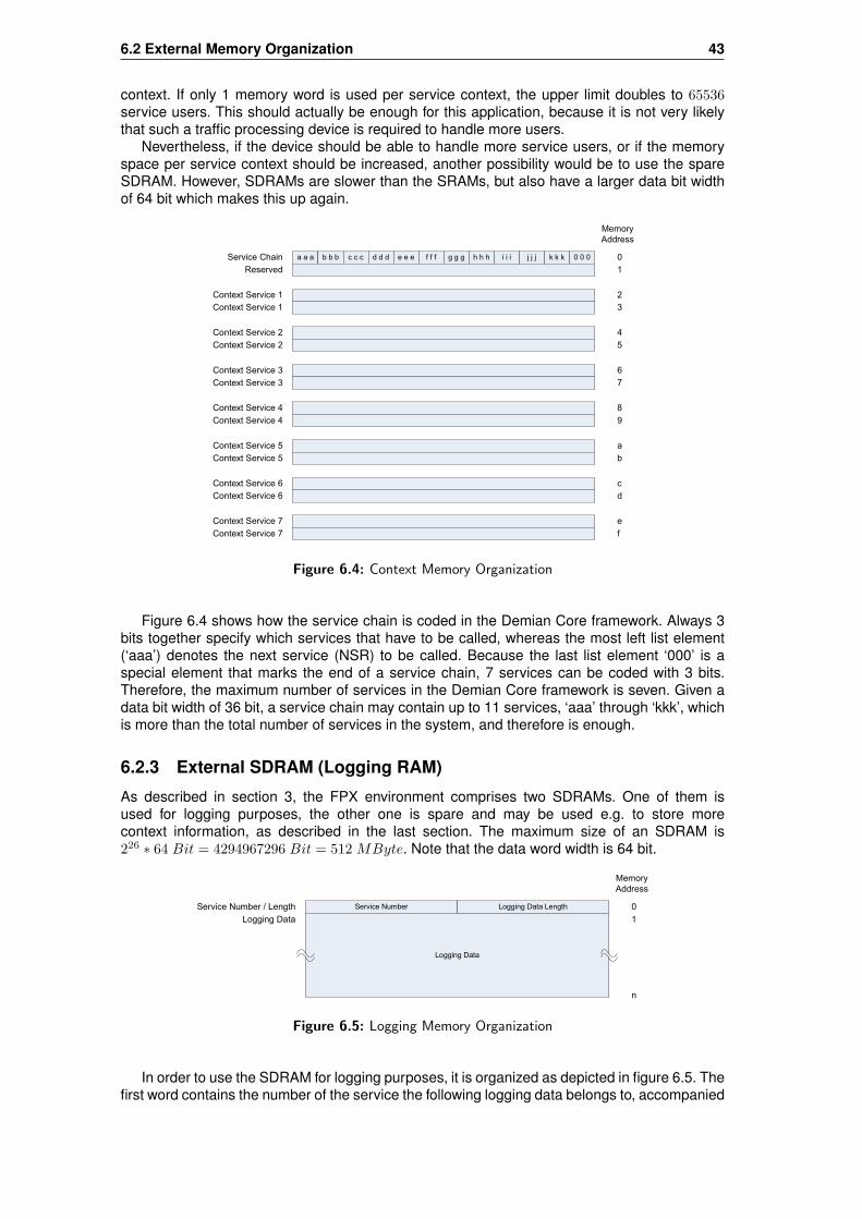
6.2 External Memory Organization 43
context. If only 1 memory word is used per service context, the upper limit doubles to 65536service users. This should actually be enough for this application, because it is not very likelythat such a traffic processing device is required to handle more users.
Nevertheless, if the device should be able to handle more service users, or if the memoryspace per service context should be increased, another possibility would be to use the spareSDRAM. However, SDRAMs are slower than the SRAMs, but also have a larger data bit widthof 64 bit which makes this up again.
Service Chain
Reserved
Context Service 1
Context Service 1
Context Service 2
Context Service 2
Context Service 3
Context Service 3
Context Service 4
Context Service 4
Context Service 5
Context Service 5
Context Service 6
Context Service 6
Context Service 7
Context Service 7
0
1
2
3
4
5
6
7
Memory
Address
8
9
a
b
c
d
e
f
a a a b b b c c c d d d e e e f f f g g g h h h i i i j j j k k k 0 0 0
Figure 6.4: Context Memory Organization
Figure 6.4 shows how the service chain is coded in the Demian Core framework. Always 3bits together specify which services that have to be called, whereas the most left list element(‘aaa’) denotes the next service (NSR) to be called. Because the last list element ‘000’ is aspecial element that marks the end of a service chain, 7 services can be coded with 3 bits.Therefore, the maximum number of services in the Demian Core framework is seven. Given adata bit width of 36 bit, a service chain may contain up to 11 services, ‘aaa’ through ‘kkk’, whichis more than the total number of services in the system, and therefore is enough.
6.2.3 External SDRAM (Logging RAM)
As described in section 3, the FPX environment comprises two SDRAMs. One of them isused for logging purposes, the other one is spare and may be used e.g. to store morecontext information, as described in the last section. The maximum size of an SDRAM is226 ∗ 64 Bit = 4294967296 Bit = 512 MByte. Note that the data word width is 64 bit.
Service Number
Logging Data
Service Number / Length
Logging Data
0
1
Memory
Address
n
Logging Data Length
Figure 6.5: Logging Memory Organization
In order to use the SDRAM for logging purposes, it is organized as depicted in figure 6.5. Thefirst word contains the number of the service the following logging data belongs to, accompanied

44 Implementation Considerations
by a length field. Then, the logging data follows, as it was saved by the service in the internallogging RAM. After the logging data, an other service will be able to save its logging data.
6.3 Internal Memory Organization
Besides the external memories available in the FPX environment, the FPGA itself has also itsown different kinds of internal memories, called BlockRAM and DistributedRAM, as described inchapter 3. Since the DistributedRAMs are used for the logic cells, such as for the implementationof the services and the framework itself, they should not be wasted for buffers. On the otherhand, the BlockRAM can only be used as RAMs and are therefore suited for the use as buffers.However, DistributedRAMs can be used to implement single flags or small fields, such as theflags and fields associated with each data buffer. The internal memories are described in thefollowing sections.
6.3.1 Data Buffer
As described in chapter 3, the FPGA has only 160∗4096 Bit = 655360 Bit = 80 kBytes of inter-nal BlockRAM. Since the IP wrapper also needs some buffers, the Demian Core framework mayuse only about 64 kBytes, which would actually be barely enough to buffer an IP packet with amaximum allowed payload of 64 kBytes. But since it is assumed that the MTU (maximum trans-mission unit) is 1500 Bytes, as described in chapter 4, we only need to be able to buffer 1500bytes. If four BlockRAMs were combined, a buffer size of 4∗4096 Bits = 16384 Bits = 2 kBytescould be created. But this would mean that 548 Bytes were wasted. Since the BlockRAMsshould be used economically, a buffer size of 1536 Bytes is used, as depicted in figure 6.6.Section 6.3.4 will show how this buffer size can be constructed out of four BlockRAMs.
Whereas the first 1500 bytes of the buffer are used to buffer an IP packet, the remaining 36bytes can be used to save any data or state information that has to be associated with the storedIP packet, such as global triggering information (remember the notification facility described inchapter 5) or temporary data.
1500 Bytes
Data Buffer
36 Bytes
Reserved, e.g. used
for global Triggers
0
Memory
Address
1499
1500
1535
Figure 6.6: Internal Data Buffer Memory Organization
6.3.2 Internal Context SRAMs and Scratch SRAMs
According to figure 5.1, each service slot has a context RAM and a scratch RAM associated withit. In order to not waste too much of the internal BlockRAMs, the context RAM and the scratcharea of a service may be combined in one single BlockRAM, as depicted in figure 6.7. This ispossible because the BlockRAMs are dual port RAMs, which allows the LWC and the serviceto simultaneously access the context area of the RAM. The scratch area can be combined withthe context RAM, because only the service needs to access the scratch RAM, and the LWCwill not touch this area. Assuming that 12 service users have to be handled, as described insection 5.2.2, and that for each service context two memory locations are needed, as described
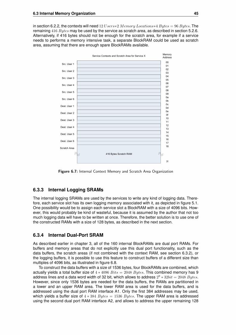
6.3 Internal Memory Organization 45
in section 6.2.2, the contexts will need 12 Users∗2 Memory Locations∗4 Bytes = 96 Bytes. Theremaining 416 Bytes may be used by the service as scratch area, as described in section 5.2.6.Alternatively, if 416 bytes should not be enough for the scratch area, for example if a serviceneeds to performs a memory intensive task, a separate BlockRAM could be used as scratcharea, assuming that there are enough spare BlockRAMs available.
Src. User 100
01
02
03
04
05
Memory
Address
06
07
08
09
0a
0b
0c
0d
Src. User 2
Src. User 3
Src. User 4
Src. User 5
Src. User 6
Dest. User 1
Dest. User 2
Dest. User 3
Dest. User 4
Dest. User 5
Dest. User 6
Service Contexts and Scratch Area for Service X
0e
0f
10
11
12
13
14
15
16
17
416 Bytes Scratch RAM
18
7f
Scratch Area
Figure 6.7: Internal Context Memory and Scratch Area Organization
6.3.3 Internal Logging SRAMs
The internal logging SRAMs are used by the services to write any kind of logging data. There-fore, each service slot has its own logging memory associated with it, as depicted in figure 5.1.One possibility would be to assign each service slot a BlockRAM with a size of 4096 bits. How-ever, this would probably be kind of wasteful, because it is assumed by the author that not toomuch logging data will have to be written at once. Therefore, the better solution is to use one ofthe constructed RAMs with a size of 128 bytes, as described in the next section.
6.3.4 Internal Dual-Port SRAM
As described earlier in chapter 3, all of the 160 internal BlockRAMs are dual port RAMs. Forbuffers and memory areas that do not explicitly use this dual port functionality, such as thedata buffers, the scratch areas (if not combined with the context RAM, see section 6.3.2), orthe logging buffers, it is possible to use this feature to construct buffers of a different size thanmultiples of 4096 bits, as illustrated in figure 6.8.
To construct the data buffers with a size of 1536 bytes, four BlockRAMs are combined, whichactually yields a total buffer size of 4 ∗ 4096 Bits = 2048 Bytes. This combined memory has 9address lines and a data word width of 32 bit, which allows to address 29 ∗ 32bit = 2048 Bytes.However, since only 1536 bytes are needed for the data buffers, the RAMs are partitioned ina lower and an upper RAM area. The lower RAM area is used for the data buffers, and isaddressed using the dual port RAM interface A1. Only the first 384 addresses may be used,which yields a buffer size of 4 ∗ 384 Bytes = 1536 Bytes. The upper RAM area is addressedusing the second dual port RAM interface A2, and allows to address the upper remaining 128

46 Implementation Considerations
bytes. This is accomplished by setting the highest two address lines constantly to 1, whichmakes sure that the lower memory area containing the data buffer can not be accessed throughthe interface A2. On the other hand, it is forbidden to use addresses >384 for interface A1,because otherwise the upper RAM area would be overwritten.
This way of arranging the BlockRAMs yield one buffer of size 1536 bytes, and four smallerbuffers of 128 bytes each. The large buffer is used to buffer an IP packet, whereas the four smallbuffers can be used e.g. as logging buffers or as scratch areas.
A1[8..0]
A1[8..0]
A1[8..0]
A1[8..0]
D1[7..0]
D1[7..0]
D1[7..0]
D1[7..0]
D2[7..0]
D2[7..0]
D2[7..0]
D2[7..0]
A2[8..0]
A2[8..0]
A2[8..0]
A2[8..0]
D1[7..0]
D2[7..0]
D1[7..0]
D2[7..0]
D1[7..0]
D2[7..0]
D1[7..0]
D2[7..0]
D1[31..0] D1[31..0]
D1[31..24]
D1[23..16]
D1[15..8]
D1[7..0]
A1[8..0]
D2[7..0]
D2[7..0]
D2[7..0]
D2[7..0]
D1[31..24]
D1[23..16]
D1[15..8]
D1[7..0]
A1[8..0] (0..383)
A1[8..0] (0..383)
A1[8..0] (0..383)
A1[8..0] (0..383)
A2[6..0] (0..127)
A2[6..0] (0..127)
A2[6..0] (0..127)
A2[6..0] (0..127)
A2[8]=1 A2[7]=1
D2[7..0]
D2[7..0]
D2[7..0]
D2[7..0]
A2[8]=1 A2[7]=1
A2[8]=1 A2[7]=1
A2[8]=1 A2[7]=1
(384Bytes = 3072Bits)
(128Bytes = 1024Bits)
(384Bytes = 3072Bits)
(128Bytes = 1024Bits)
(384Bytes = 3072Bits)
(128Bytes = 1024Bits)
(384Bytes = 3072Bits)
(128Bytes = 1024Bits)
Dual-Port RAM (512x8Bit)
Dual-Port RAM (512x8Bit)
Dual-Port RAM (512x8Bit)
Dual-Port RAM (512x8Bit)
Figure 6.8: Constructed Buffer Size of 1536 Bytes, built with four Dual-Port RAMs
6.3.5 Internal Flags and Fields
Internal flags and small fields, such as the ones associated with each buffer, or the "BufferFull" flags, are best implemented using some bits of the DistributedRAMs. However, if doingso, the space they need will not be available for the logic cells anymore. But this is the betterway of implementation, because it would not be convenient to use BlockRAMs for this purpose.Another reason is that if BlockRAMs were used, the flags and fields could not simultaneously beaccessed anymore. Table 6.2 gives an overview of how many bits will be occupied by the flagsand fields associated with one data buffer. The "Buffer Full" flags associated with the loggingbuffers are neglected, because they depend on the number of services in the system and not onthe number of data buffers. There are as many "Buffer Full" flags needed as there are serviceslots in the system.
For six data buffers, this will need 6 ∗ 95 Bits = 570 Bytes, neglecting the "Buffer Full" asmentioned before. This means that only 613830 Bits will be available for the logic cells insteadof 614400 Bits. This is a reduction by 0.093%, which is acceptable.

6.4 IP Wrapper Signals 47
Flag / Field Size in BitsBuffer in Use 1Src./Dest. Chain 1Src. Chain 36Dest. Chain 36Src. User 3Dest. User 3Data Buffered 1Search Service 1Services Done 1Drop Buffer 1Byte Count 11Total 95
Table 6.2: Memory utilization of the flags and fields for one buffer
6.4 IP Wrapper Signals
Figure 6.9 shows how the Demian Core framework interfaces with the surrounding IP wrapper[Wra]. Actually, the IP wrapper seems not to be a true IP wrapper, since it transmits not onlyIP packets, but additional data words that arise from the transmitted ATM cells. However, thisadditional data words may be considered by the Demian Core framework as overhead. Whatthe IP wrapper really does is setting some control lines which help the Demian Core frameworkto extract the actual IP packet from the arriving byte stream (or word stream, as 32 bit words arebeing transmitted). In order to be able to successfully communicate with the IP wrapper, onlythe following five or six signal lines are necessary besides the 32 bit data bus:
data: This is the data bus which is needed to transfer the IP packets from the IP wrapper tothe Demian Core framework and back again. The data bus is 32 bit wide, which implies that thedata is transmitted word by word.
dataen (Data Enable): Since it is possible that the arriving data stalls, it is necessary to usethis control line together with the data bus, in order to make sure that the transmitted data isvalid.
sof (Start of Frame): This signal marks the start of the transmitted IP packet, including theATM overhead. It is actually not used by the Demian Core framework, since the ATM overheadis not of interest.
soip (Start of IP): This control line signals the actual start of an IP packet within the arriv-ing byte stream, which makes it easy for the Input Buffer Controller (IBC) and the Lookup &Writeback Controller (LWC) to detect the actual start of an IP packet and to commence theirwork.
sop (Start of Payload): This control line signals the start of the payload within the arrivingbyte stream. However, this control line is not really used by the Demian Core framework, sincethe header and the payload are buffered in the same data buffer. If a service needs to inspectthe payload, it has to use the length field in the IP header in order to find out where the payloadstarts. As an extension, this control line could be used to save the start of the payload in anadditional field associated with the buffers, in order to speed up payload accesses.
eof (End of Frame): This control line signals the end of the arriving byte stream and thereforealso the end of an IP packet.

48 Implementation Considerations
tca (Transmission Cell Available): This control line is intended to use for congestion control.However, it is not implemented by the IP wrapper itself, and therefore may not be used by theDemian Core framework.
IP Wrapper
Demian Core
Framework
data
dataen
sof
soip
sop
eof 1
32
1
1
1
1
1 tca
data
dataen
sof
soip
sop
eof 1
32
1
1
1
1
1tca
Figure 6.9: IP Wrapper Signals

Chapter 7
Performance Analysis
The framework described in chapter 5 has a few bottlenecks that have to be kept in mind ifheading for an implementation, namely the Lookup & Writeback Controller (LWC), and the Ser-vices (SRV) themselves. While section 7.1 covers some general timing constraints, section 7.2addresses the problems existing in the LWC, and also gives some important hints. Section 7.3deals with system performance issues in general, such as overall throughput, best and worstcase scenarios, interaction between the buffers and the services, and so on.
7.1 General Timing Constraints
In order to be able to do a performance analysis, it is crucial to be aware of some generalminimum and maximum timing constraints that exist due to the FPX environment. First of all,most important is an estimation of the best and worst case scenarios for the packet arrival rates,and therefore indirectly also of the expected minimum and maximum distances between the IPpackets, which depend on the packet arrival rates. Also important is a statement about theminimum and maximum IP packet sizes that have to be processed. For the following constraintsestimations, it is assumed that IP packets arrive at full link speed, meaning that the 2.5 GBitATM link is fully loaded.
7.1.1 Minimum IP Packet Size
According to the Internet Protocol specification, the payload size of an IP packet may be zero.This is the worst case scenario, because during the packet arrival the LWC has to perform theuser lookups and context fetches/writebacks. Hence, this also means that the time between twoIP packets will be minimal, because once an IP packet of payload size zero and of a minimumheader length of 20 Bytes is received, the next IP packet might immediately follow.
But luckily, since in the FPX environment described in chapter 3 ATM is used as transportmedium, a minimum transmission time for IP packets is guaranteed anyway, as described inthe next section. This is due to the fact that in order to transport IP packets over ATM, the IPpackets have to be encapsulated into ATM cells, using the ATM Adaption Layer 5 (AAL5) [Tan],as depicted in figure 7.1. Since ATM cells always have a constant size of 53 Bytes, the remainingspace will be padded, because only entire ATM cells may be transmitted. This means that if aminimum sized IP packet is to be transferred, always at least 53 bytes have to be transmitted,which ensures a guaranteed minimum transmission time for a minimum sized IP packet.
IP Header AAL5 TrailerATM
HeaderPadding
5 Bytes 20 Bytes 20 Bytes 8 Bytes
Figure 7.1: ATM Cell containing an IP Packet with Payload Size Zero
49

50 Performance Analysis
7.1.2 Maximum Packet Arrival Rate
If it happens that minimum sized IP packets arrive at full link speed, which is the worst casescenario, this will define the maximum packet arrival rate that has to be expected. The maximumnumber of ATM cells to arrive, and thus the maximum IP packet arrival rate, is 2488.32 MBit/s
53 Bytes ∗ 8 Bit ≈6153756 IP Packets
s . In other words, the transmission of a minimum sized IP packet always takesat least 53 Bytes ∗ 8 Bit ∗ 1
2488.32 MBit/s ≈ 162.5 ns, which is the guaranteed time available forthe LWC to perform lookups.
However, since on an ATM link not all cells may be used for IP packet transmission, due tothat a certain percentage is reserved for ATM maintenance or other applications, the effectivemaximum packet arrival rate will be slightly smaller and the available time for lookups a little bitlarger. But to be on the safe side, let’s use these numbers for the future performance analysis.
7.1.3 Maximum IP Packet Size
According to the Internet Protocol specification, the maximum payload size of an IP packet maybe 64 kBytes. But as described in chapter 4 and in [Sch], arriving IP packets will never exceeda size of 1500 bytes, because the underlaying transport medium is assumed to be ethernet,and therefore the maximum transfer unit (MTU) is limited to 1500 Bytes. This also explains thechosen data buffer size of 1536 Bytes explained in chapter 6. If larger IP packets are to betransmitted, they will be fragmented by the lower layer protocol.
Again, IP packets are transmitted over ATM by encapsulating them into ATM cells of a fixedsize of 53 Bytes. Since 5 Bytes of an ATM cell are reserved for the ATM header, only 48 Bytesare available for the ATM payload. This means that the transmission of a maximum sized IPpacket actually causes 1500 Bytes
48 Bytes ≈ 32 ATMCells to be transferred.
7.1.4 Minimum Packet Arrival Rate
If it happens that all arriving IP packets are maximum sized packets, which is the best casescenario if the link is fully loaded, this means that the expected minimum packet arrival ratewill be at least 2488.32 MBit/s
32 ∗ 53 Bytes ∗ 8 Bit ≈ 192305 IP Packetss . In other words, the transmission of a
maximum sized IP packet takes at least 32 Cells ∗ 53 Bytes ∗ 8 Bit ∗ 12488.32 MBit/s ≈ 5.2 ms,
which is the maximum time available for the LWC to perform lookups.
7.2 User Lookup and Context Fetch Timing
In order to minimize the packet drop rate due to slow or failed service user lookups, and thereforeto achieve a high throughput, it is important to make sure that the LWC’s service user lookup,context fetch, and context writeback operations work as efficiently as possible. For this reasonit is important to know how much time the LWC needs in the worst case, by means of clockcycles, to perform a service user lookup. Both source and destination service user lookupshave to be completed within the transmission time of a minimum sized IP packet, as describedin section 7.1.2, in order to satisfy the maximum packet arrival rate constraint. Otherwise, thedistance between the IP packets would have to be increased, in order to make sure that theLWC has enough time to perform the lookups. Thus, this would mean a reduction of the packetarrival rate, which consequently means a reduced throughput.
The time needed to perform a lookup depends on the kind of user to be looked up. Theworst case is if the service user to be looked up is a single host, because this means that themaximum prefix length of 32 bit (Src./Dest. bit excluded) has to be found. Using the "Tree BitmapAlgorithm" described in section 6.1, this means that a lookup for a host takes 9 clock cycles. Sothe worst case is if both source and destination IP Addresses lead to service users that have amaximum prefix length of 32 bit, namely single hosts. This means that the lookups for a given IPpacket last 18 clock cycles in total. If the user lookups could be parallelized, for example by usingan external dual port SRAM instead of a regular SRAM, the LWC could even get along with asless as only 10 clock cycles. Both lookups could then be performed simultaneously, althoughdisplaced by 1 clock cycle, due to the fact that the source and the destination IP addresses are

7.2 User Lookup and Context Fetch Timing 51
also displaced by 1 in the IP header. However, in the current FPX environment it is not possibleto parallelize the lookups, because no external dual port RAM is available.
7.2.1 Required Clock Frequency
As described in section 7.1.2, the time that is at the LWC’s disposal for the service user lookupsis basically determined by the minimum length of an IP packet, and thus by the maximumpacket arrival rate. This means that in order for the LWC to complete the lookups in time, the18 Clock Cycles needed for the lookups have to be completed within the minimum sized IPpacket’s transmission time of 162.5 ns. Thus, the required clock period has to be smaller orequal to at least 162.5 ns
18 Clock Cycles ≈ 9.027 ns, which means that in order for the LWC of being ableto perform the lookups at full line speed, the FPGA in the FPX environment has to be clockedwith at least 1
9.027 ns≈ 110.8 MHz.
However, the FPX architecture explained in chapter 3 is clocked with only 100 MHz, whichis just a little bit too low in order to get along with this worst case scenario. Now, there are twopossibilities how to cope with this issue:
Either, one has to ensure that only every other ATM cell is used for IP traffic encapsulation,assuring the LWC of enough time to complete the lookups. This would actually mean that thelink load may not exceed 50%, which would still meet the requirements though. According tothe assignment amendments in appendix A, the Demian Core framework is only required to beable to handle 20% of the ATM link capacity. Anyway, this solution is not satisfying, since thethroughput would have to be dramatically limited, and because it would be difficult to grant thisdrastic constraint all the time.
Another simple possibility is to increase the FPGA’s clock frequency by 30%, up to the max-imum allowed frequency of 130 MHz specified in the data sheet [Xila]. This is equal to a clockperiod of 1
130 MHz = 7.69 ns, which grants the LWC 162.5 ns7.69 ns = 21.125 ≈ 21 Clock Cycles per
ATM cell, and thus per a minimum sized IP packet, which is enough to perform the lookups atline speed. This means that with a clock frequency of 130 MHz we are on the safe side, be-cause only 18 Cycles are needed for the lookups, but 21 Cycles are available, which means that3 Cycles are left over as a safety margin. Therefore, and because it allows service user lookupsat line speed, this second solution is clearly to be preferred.
Other important issues that have been neglected so far are the number of contexts to befetched, and the fact that the LWC not only has to perform the lookups, but also the contextwritebacks. The minimum number of clock cycles the LWC needs to perform all of its taskstherefore not only depends on the user’s prefix lengths, but also on the number of services inthe system, by means of the number of contexts that have to be fetched and written back, andalso on the context’s size. Within the 18 clock cycles, the LWC also has to be able to fetchand writeback contexts of both source and destination service users. Given this restriction, theLWC supports no more than 4 service contexts with a size of 1 memory access (e.g. 36 bits),according to figure 7.2: One cycle is used to fetch the service chain, shown in cycles 14 and 23,and four cycles are needed to fetch the four service contexts (cycles 15-18 and 24-27). As youcan see, there are always four cycles left which the LWC can use to perform context writebacks.The following section explains how the lookups could be sped up even more, and how moreservice contexts could be handled.
7.2.2 How to Speed Up the Lookups
There are actually two alternatives how the memory operations, such as service user lookups,context fetches, and context writebacks, could further be sped up.
One possibility would be to further increase the clock frequency, since the FPGA’s datasheet [Xila] allows a maximum clock rate of 416 MHz, which is about 3.2 times higher than the130 MHz mentioned before. However, according to the specification this frequency may only beused within the FPGA. Since the user and context RAMs are external memories, it would onlybe possible to increase the frequency for purely chip internal operations, such as to speed upthe services. Therefore, this method can not be used to further speed up the lookups.
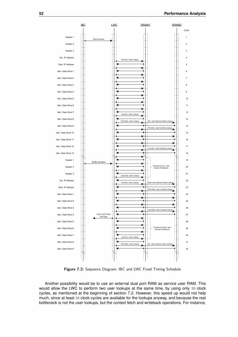
52 Performance Analysis
Header 1
Header 2
Header 3
Src. IP Address
Dest. IP Address
Buffer Number
Idle / Data Word 1
Idle / Data Word 2
Idle / Data Word 3
Idle / Data Word 4
Idle / Data Word 5
Idle / Data Word 6
Idle / Data Word 7
Idle / Data Word 8
Idle / Data Word 9
Idle / Data Word 10
Idle / Data Word 11
Idle / Data Word 12
Header 1
Header 2
Header 3
Src. IP Address
Dest. IP Address
Idle / Data Word 1
Idle / Data Word 2
Idle / Data Word 3
Idle / Data Word 4
Idle / Data Word 5
Idle / Data Word 6
Idle / Data Word 7
Idle / Data Word 8
IBC LWC SRAM1 SRAM2
Idle / Data Word 13
Buffer Number
Users (not) Found
Src. User Service Chain Lookup
First Src. User Lookup
First Dest. User Lookup
First Src. User Lookup
First Dest. User Lookup
Idle / Data Word 9
1
2
3
4
5
6
7
8
9
10
11
12
13
14
15
16
17
18
19
20
21
22
23
24
25
26
27
28
29
30
31
32
Cycle
Last Src. User Lookup
First Src. User Context Lookup
Last Src. User Context Lookup
Last Dest. User Lookup
Dest. User Service Chain Lookup
First Dest. User Context Lookup
Last Dest. User Context Lookup
Last Src. User Lookup
Src. User Service Chain Lookup
Set Flags
Timeslot for Src. User
Context Writebacks
Timeslot for Dest. User
Context Writebacks
Figure 7.2: Sequence Diagram: IBC and LWC Fixed Timing Schedule
Another possibility would be to use an external dual port RAM as service user RAM. Thiswould allow the LWC to perform two user lookups at the same time, by using only 10 clockcycles, as mentioned at the beginning of section 7.2. However, this speed up would not helpmuch, since at least 18 clock cycles are available for the lookups anyway, and because the realbottleneck is not the user lookups, but the context fetch and writeback operations. For instance,

7.3 Buffer/Service Congestion 53
if both source and destination user lookups were performed in only 10 clock cycles, the problemof fetching and writing back the contexts would still remain the same: context fetches of bothservice users would have to be performed simultaneously, and in order to really gain something,the writebacks would also have to be performed at the same time. This is quite unrealistic, sincethis scenario would require something like an external quad port RAM in order to satisfy all fourneeds. However, there are quad port RAMs available on the market, but this is only useful forchip internal RAMs [Xilb][Alt], because too many chip pins would be needed. Thus, this variantis too complicated and does not pay, and is therefore abandoned.
Consequently, the goal must actually not be to speed up the user lookups, but to optimize thecontext fetch and writeback operations. If an external dual port RAM would be used as servicecontext RAM, it would be possible to simultaneously fetch and writeback contexts, which wouldbe a real gain. This would allow to handle up to eight service contexts, which is twice as much aswithout dual port RAM. However, external dual port RAMs might cause new problems, becausemore data and address lines are needed. According to the Xilinx specification [Xila], the FPGAhas 512 user I/O pins that can be used, which is quite a lot. Therefore, this is the only variantthat seems realistic and is a real gain in performance.
There exist some other possibilities how the memory access performance could be in-creased. The best solution would be if no external RAM had to be used at all, because thiswould allow to use the maximum specified FPGA internal frequency of 416 MHz, which wouldspeed up memory accesses by a factor of 3.2. Additionally, an other FPGA from the same se-ries could be used, such as the XCV3200E, which provides more internal BlockRAMs, moreDistributedRAMs, and more I/O pins. Eventually, this would allow to store the service users andthe service contexts within the FPGA, which should actually be the goal in order to achieveoptimum performance. Furthermore, this would allow quad port RAMs to be used, which gaveanother speedup of up to a factor of 4, since context fetches/writebacks for both users could beexecuted simultaneously.
As you can see, the recipe for more speed is on the one hand to avoid the use of externalRAM because they are a bottleneck and slow down the accesses, and on the other hand to useinternal dual port RAMs, or even quad port RAMs, as described before and in [Xilb][Alt].
However, for the sake of simplicity it is for now the best to stick with the fixed timing dia-gram depicted in figure 7.2. Once a solution has been implemented that works fine, the abovementioned advanced considerations can be implemented. To use a fixed time schedule means,that a service user lookup will always last 9 cycles, even if it could be faster. Similarly, contextfetches and writebacks will always last 4 clock cycles each. Such a fixed timing schedule easesan implementation and is concise, why the author prefers such a solution.
7.3 Buffer/Service Congestion
In order to analyze the performance of the interplay between the services, the buffers, andthe arriving IP packets, it is best to assume a sample scenario, as described in the assignmentamendments in appendix A. Therefore, a system with four different services and different servicetimes, and three different logical service chains is assumed. Additionally, a fourth service chainis introduced that is mirror-inverted to the third service chain, which will allow to show criticaltiming situations. According to the task description in appendix A, 1000 service users couldbe assumed for this analysis. However, since the LWC is able to perform the lookups at fulllink speed, as described in section 7.2, the number of services does not have an impact onthe throughput and thus on the performance. Actually, the specification of three different logicalservice chains implies three different service users in the system. Therefore, the allegation of1000 service users is not relevant and can therefore be neglected.
Table 7.1 summarizes the four services and states the assumed number of clock cycleseach service needs to accomplish its task. Furthermore, a description of what tasks a serviceexecutes within which clock cycles is given. But actually it does not matter for this analysis howexactly a service performs its tasks, by means of what tasks are performed in which clock cycle.At the end of the day, it is only important to know how many clock cycles a service needs in total(service time).
The following sections highlight the boundaries for the best and worst case scenarios usingthis sample scenario. Thereby, it is assumed that the system is clocked with the maximum

54 Performance Analysis
frequency of 130 MHz, as described in chapter 6. This means that 21 clock cycles are grantedto the LWC and therefore also to the services to perform their tasks.
SID Service Cycles Cycle: Task Description
1 Packet Counter SRV 2
1: - read context from context RAM- increment packet counter
2: - write context to context RAM- update buffer flags
2 Rate Limiting SRV 5
1: - read context from context RAM- read protocol field from header
2: - update packet counter- update timestamp
3: - check trigger condition4: - eventually drop IP packet5: - write context to context RAM
- update buffer flags
3Packet Rate perProtocol CounterSRV
3
1: - read context from context RAM- read protocol field from header
2: - update packet counter- update timestamp
3: - write context to context RAM- update buffer flags
4 Blocking SRV 2
1: - read context from context RAM- update packet drop counter
2: - drop IP packet- write context to context RAM- update buffer flags
Table 7.1: Four Services with different Service Times
Table 7.2 shows the assumed service chains for four different service users. All chains maybelong to a source and/or to a destination service user. Note that the trailing zeroes denote theend of a service chain, as described in chapter 5.
Service User Service ChainService User 1 1, 2, 3, 4, 0Service User 2 2, 3, 1, 4, 0Service User 3 1, 4, 3, 2, 0Service User 4 2, 3, 4, 1, 0
Table 7.2: Four Service Users with different logical Service Chains
7.3.1 Best Case Scenarios
Figure 7.3 shows three different timing diagrams for the best case scenarios (a,b,c) with differentservice chain constellations, which are explained in the following paragraphs.
Timing diagram a) assumes that all arriving IP packets belong to the same source serviceuser, and that no user is found for the destination service user. This is clearly the best case,because all 21 cycles may be used to process the source user’s service chain. All services canbe processed sequentially, and there are even 9 cycles left. This also means that no additionallatency is introduced, and the performance will be 100%. Thus, the latency is the sum of allservice times, which makes 12 cycles. However, this scenario assumes that only IP packetsfrom source service user 1 arrive. Of course, the same scenario also holds if only the destinationservice user is found instead of the source service user.

7.3 Buffer/Service Congestion 55
Service 4
Service 3
Service 2
Service 1
Wait
Service 4
Service 3
Service 2
Service 1
Wait
02
46
810
12
14
16
24
26
28
30
32
34
36
38
44
46
48
50
52
54
56
58
60
18
20
40
42
62
64
Service 4
Service 3
Service 2
Service 1
Wait
Service 4
Service 3
Service 2
Service 1
Wait
Service User 1 (Src.)
Service User 1 (Src.)
Service User 1 (Dest.)
Service User 1 (Src.)
Service User 2 (Dest.)
Service User 3 (Src.)
Service User 4 (Dest.)
a)
b)
c)
d)
22
02
46
810
12
14
16
24
26
28
30
32
34
36
38
44
46
48
50
52
54
56
58
60
18
20
40
42
62
64
22
02
46
810
12
14
16
24
26
28
30
32
34
36
38
44
46
48
50
52
54
56
58
60
18
20
40
42
62
64
22
02
46
810
12
14
16
24
26
28
30
32
34
36
38
44
46
48
50
52
54
56
58
60
18
20
40
42
62
64
22
Service 4
Service 3
Service 2
Service 1
Wait
Source Service User
Destination Service User
e)
02
46
810
12
14
16
24
26
28
30
32
34
36
38
44
46
48
50
52
54
56
58
60
18
20
40
42
62
64
22
Dest.
Wait
Dest.
Wait
Dest.
Wait
Src.
Wait
Src.
Wait
Figure 7.3: Best Case (a,b,c) and Worst Case (d,e) Timing Diagrams

56 Performance Analysis
Timing diagram b) assumes that besides the scenario shown in timing diagram a) also thedestination service user is found, which happens to be the same as the source service user,indeed service user 1. Therefore, the service chains to be processed are the same for bothusers, which allows the services to interleave the service chains, as shown in figure 7.3 b). Inthis case, the slowest service will determine the maximum additional latency to be expected, inaddition to the 12 cycles latency described in the last paragraph, which is 5 clock cycles causedby service number (SID) 2. Again, the throughput in this case will be 100%, but the additionallatency might vary up to the service time of the slowest service.
Timing diagram c) shows the scenario that service user 1 is found for the source IP address,and service user 2 for the destination IP address. Again, the slowest services of both servicechains will determine the maximum additional latency to be expected. Luckily, for this best casescenario the service chains accidentally happen to cause no waiting times, and therefore nocongestion, thus a throughput of 100% can be expected. However, the additional latency mightvary up to the cumulated slowest service times of both service chains.
To conclude, the ultimative best case scenario is if only one service user is found. Also greatis the second scenario where both source and destination service users are identical. The thirdscenario already depends on how the services within the service chains are arranged. In thebest case, full throughput can be reached, and only small latencies are introduced.
However, for these best case scenarios it is assumed that the total number of (interlaced)service times of both service chains – or one service chain if only one service user could befound – does not exceed the available 21 clock cycles. Otherwise it would not be a best casescenario anymore, and if the arrival rate were too high, IP packets would have to be dropped.However, this case is covered in the next section.
7.3.2 Worst Case Scenarios
Figure 7.3 shows two different timing diagrams (d,e) for the worst case scenarios with differentservice chain constellations, which are explained in the following paragraphs.
Timing diagram d) shows the scenario that service user 3 is found for the source IP address,and service user 4 for the destination IP address. Since the last service of service user 3 isservice number 2, featuring the longest of all service times, and since the service chain forservice user 4 is the mirror-inverted variant of service chain 3, this creates a constellation whereespecially long waiting times arise between the service chains. Because service 2 is still busywhen the destination service chain should be processed, as you can see from figure 7.3, waitingcycles are introduced for the destination service chain in cycles 9-12 and 51-54. Similarly, theprocessing of the source service chain has to be delayed in cycles 21-24 and 31-35.
In order to completely process the service chains of both service users for the first arriving IPpacket, 24 cycles are needed, but only 21 cycles are available. Thus one might think that some-when later IP packets would have to be dropped. Furthermore, the processing of the sourceservice chain for the second arriving IP packet has to be put off by 3 cycles to cycle 24. Onthe other hand, this will allow to start the processing of the destination service chain on timein cycle 30. But this forces the processing of the source IP chain to be interrupted for 4 cyclesin cycle 31. Anyway, in cycle 42 both service chains have completely been processed, so thatthe processing of the third arriving IP packet may start on time. Therefore, surprisingly no pack-ets will have to be dropped in this scenario, which will lead to a 100% packet throughput. Theadditional latency to be expected is also within an acceptable limit, e.g. 7 clock cycles for thisscenario. Actually this means that this example is not really a worst case scenario, because theservice chains are such that the system is able to recover from the delays.
Timing diagram e) gives a general, absolutely worst case scenario. It is assumed that theservice chains are constructed such that many collisions exist and only one service may beexecuted at a given time. This situation could for example arise if many different service userswere involved in a way that does not allow any services to be executed in parallel. This means
7.3 Buffer/Service Congestion 57
that the processing of one IP packet will always last 24 cycles, whereas only 21 cycles areactually available. Thus, if IP packets arrive at full line speed of 2.5 GBit/s, this means that overtime about 100 ∗ 24−21
21 ≈ 15% of the arriving IP packets will have to be dropped. On the otherhand, if no IP packets may be dropped, the link load may not exceed a value of 100 ∗ 21
24 ≈ 87.5%over time. In order to make sure that this constraint is not exceeded, this means that every 8th
ATM cell may not be used for IP traffic. Furthermore, this also means that the additional latencymay rise as high as 1 IP packet, and thus 21 clock cycles. This creates a backlog of 1 IP packetthat the Demian Core framework has to be able to store.
To summarize, the ultimative worst case scenario is if only one service can be executed at agiven time, due to the way how the services are arranged in the service chains, and the char-acteristics of the arriving IP packets. If this happens, either IP packets will have to be dropped,or the ATM link may be loaded with only 87.5% of the possible line speed. The additional la-tency introduced in the worst case scenario is 21 clock cycles. The next section addresses thecharacteristics of the arriving IP packets, such as bursts.
7.3.3 Conclusion
The scenario used in the last section assumes that the cumulated service time for both serviceusers is smaller than the available 21 clock cycles. Furthermore, for the average case, thearriving IP traffic is assumed to be uniformly distributed, thus creating only moderate backlogs.If this should not be the case, or in the event of bursty IP traffic, the overall latency and thus thecreated backlog will rise and eventually reach a limit such that all internal data buffers are fulland packets have to be dropped.
However, in the assignment amendments in appendix A it is demanded that the DemianCore framework be able to handle ∼10% average and ∼20% peak load of a 2.5 Gbit/s ATMbackbone. In the average case these requirements are clearly met, since the framework isable to process IP traffic up to a link load of ∼87.5%, which is about 2.1 Gbit/s. Of coursethe calculated maximum load of 87.5% is not fixed, since it heavily depends on the number ofservices and their service times. If the link is loaded only with the requested peak load of ∼20%,which is about four times less than possible, this means that more time would be available forthe services. Thus, about twice as many services could be inserted into each service chain,assuming that the service times are about the same as shown in table 7.1. Another possibilitywould be to support a service with a long service time, such as one that analyzes the payloadof an IP packet.
Problems arise if the cumulated number of service times for both service users exceeds theavailable time of 21 clock cycles. This means that the arrival rate would have to be kept low, inorder to grant enough time for the services to complete before the next IP packets arrive. Onthe other hand, e.g. if the arrival rate will never exceed the specified peak load of 20% of thelink capacity, about 4 times as much time would be available for the services.
Another problem exists if bursty IP traffic arrives, such as temporarily or during an attack.Since according to figure 5.1 only 6 buffers are available, the Demian Core framework is some-what vulnerable for the infinite backlog problem mentioned in section 5.5. One possibility to copewith this issue is to increase the number of data buffers in the system. Since according to chap-ter 6 there are still many unused 1536 byte sized data buffers available, the author suggests todouble the number of data buffers to 12 in order to be able to compensate slight packet arrivalrate jitter. Anyway, the problem still exists in the event of an attack. However, if the concerned IPtraffic belongs to the same service user(s), it is possible that the framework is able to deal withsuch an attack, according to the best case scenarios depicted in figure 7.3. Another solution isto install a rate limiting service as the first service within a service chain that is able to detectsuch an attack and will immediately drop the concerned IP packets.

58 Performance Analysis

Chapter 8
Conclusion and Future Work
While the last three chapters described the Demian Core framework, this section gives a sum-mary about the achieved results in section 8.1. Section 8.2 comes up with a final conclusion,while section 8.3 presents some suggestions for future work.
8.1 Summary
This section summarizes the two most important tasks that have been performed during thisthesis, namely the FPX environment description, and the development of the Demian Coreframework.
8.1.1 FPX Environment
The first part of this diploma thesis comprised of the study of the Field Programmable Port Ex-tender (FPX) environment, developed at the Washington University’s Applied Research Lab, andthe subsequent documentation, as shown in chapter 3. During the work, the FPX environmentproved to be very interesting and well suited concerning the aim of developing and implementingan IP traffic processing device. However, the FPGA used for the FPX environment lacks of largeinternal RAMs that are needed in order to process fully sized IP packets. This is partly made upby the use of external RAMs, which however proved to be a performance bottleneck, since theydo not support the dual port feature. Furthermore, the FPGA prohibits high speed access to theexternal memories, due to physical restrictions of the FPGA pads (pins). Nevertheless, the ideabehind the FPX environment is impressive, and if an FPGA with more internal RAM could beused, the performance could even more be increased.
8.1.2 Demian Core Framework
The second and most time consuming part of this diploma thesis was the development of differ-ent frameworks for an IP traffic processing device, as proposed in [Dem], and according to theassignment and the assignment amendments in appendix A. Before the Demian Core frame-work was developed, three alternative designs were proposed. However, all of them had someheavy restrictions, so that none of them was suited to be used in the real world. The DemianCore framework arose from those former three designs, in that it adopted the advantages ofall three designs, while leaving the disadvantages away. The Demian Core design is explainedin chapter 5, while chapters 6 and 7 cover implementation issues and a performance analysis,respectively.
8.2 Conclusion
The initial goals of this diploma thesis were to study the FPX environment, and subsequentlyto specify and implement a rate-limiting service and a trigger mechanism, based on the FPXenvironment. However, during the study of the FPX environment it turned out that no appropriate
59
60 Conclusion and Future Work
framework facility was available that would have allowed to specify and implement the serviceand trigger mechanism right away. Therefore, it proved that beforehand it was necessary todesign a framework which satisfies these needs, and hence the Demian Core framework wasborn.
What resulted from this diploma thesis is the design of an IP processing device frameworkthat is fast, versatile, multifunctional, and provides different trigger mechanisms that make theframework very flexible. It supports different service users, different service chains, and thepossibility of plugging in different services. IP packets can be routed through different services,according to the service chains of the concerned service users. Finally, it is acceptable for realworld usage, since it gets along with the required ∼20% peak load of a 2.5 Gbit/s ATM link.
To conclude, the most important contribution of this diploma thesis is clearly the design of anIP traffic processing device framework that is well suited for real world usage, and subsequentlycan be implemented on the FPX or another suited FPGA based architecture.
8.3 Future Work
This section points out the next steps that should be taken in the near future. In addition, it givessome ideas how the Demian Core framework can further be improved, thus allowing even moreflexibility and performance improvements.
8.3.1 Multiple Identical Services
A real need and also a challenge is the development of a framework extension that allowsmultiple services of the same kind to coexist in the system at the same time. This would openthe new possibility to e.g. duplicate slow services, such as a service that scans the payload, orservices that are highly likely to appear in most service chains. An approach how this could beaccomplished is given in section 5.5.3. Thus, such a framework extension would immediatelyresult in a higher throughput, since less buffer/service congestion has to be expected.
8.3.2 Flexible Service Chains
Another interesting method that will further improve the throughput of the Demian Core frame-work is the possibility of introducing flexible service chains. For example, it is most likely that, forsome applications or some service users, the execution order of the services within their servicechains does actually not matter for some or all services. These services could be marked with aflag that tells the scheduling algorithm whether they need to be executed in the predefined order,or the execution order does not matter. In case of buffer/service congestions, this method allowsthe scheduling algorithm to adjust the service chain accordingly, and therefore to dynamicallychange the service execution order. Thus, this method allows to bring forward another servicein order to prevent unnecessary waiting times, which will increase the overall performance.
8.3.3 User and Context RAM Updates
An issue that has been neglected so far is how the user and context RAMs can be updatedby the TCSP without service interruption, such as to add new service users or to modify theservice chain of a service user. Since the user RAM is a read only RAM from the Demian Coreframework’s point of view, a possibility would be to use two identical external user RAMs: onethat is currently in use, and another one that is on stand by and can be updated by the TCSP.Changes could then be committed by switching between the RAMs at a time when it will not doany harm to the system, such as between two service user lookups.
However, the update of the context RAM is more complex, since context data also has tobe written back by the Demian Core framework. Anyway, by using a smart algorithm, the samemethod could be applied as for the proposed service user RAM updates. Another possibility isto always reserve enough space in the context RAM, such that the contexts of one multibit nodeof the Tree Bitmap Algorithm can consecutively be stored in the context RAM, which will help toavoid difficult memory defragmentation operations.

8.3 Future Work 61
8.3.4 Trigger and Calculations in the IBC
In order to support attack mitigation, the Input Buffer Controller could be extended such that itacts as kind of an own little (trigger) service, and thus scans incoming IP packets on the fly forwell known signatures. This has the advantage that some attacks can be detected early uponIP packet arrival, which helps to mitigate denial of service attacks. If the IBC detects an attack,it could act in two different ways:
First of all, if this new functionality is implemented by means of a global trigger service, asdescribed in section 5.12, the malicious IP packet could be discarded right away, without evenbuffering it, which helps to prevent denial of service attacks. However, the use of global triggersis actually controversial, as mentioned in section 5.12.
The other possibility is that the IBC buffers the malicious IP packet anyway, but marks it asbad, using the message passing method described in section 5.12. Thus, a flag is set in thedata buffer’s reserved area, see section 6.3.1. This might trigger an other per user trigger thatcan have a closer look at the malicious IP packet.
Furthermore, the IBC could be used to pre-calculate other kinds of checksums or signaturesas the data words arrive, which will be stored in the data buffer’s reserved area. This wouldspeed up the services, because time extensive checksum calculations are already performedby the IBC and the results can immediately be used by the services.
8.3.5 Demian Core Implementation
The next major step to be taken in the near future is to implement the Demian Core frameworkas it is proposed in chapters 5-7. This could either be done in the FPX environment explained inchapter 3, at the Washington University’s Reconfigurable Network Group [Rec][ARL], which isheaded by John Lockwood, or at the ETH [TIK] department, leaded by Bernhard Plattner, in anown proprietary environment to be defined. Interesting would also be a more closer cooperationbetween the two institutions, such as a joint university research project, as mentioned in [Res].
However, the implementation of the Demian Core framework is expected to be quite exten-sive. Therefore, the author suggests that its implementation be scheduled in a separate diplomaor master thesis.

62 Conclusion and Future Work

Bibliography
[Alt] Mercury Performance-Optimized Architectures, Altera Corp., see http://www.altera.com and http://www.altera.com/products/devices/mercury/features/mcy-arch.html.
[ARL] Applied Research Laboratory, Washington University of St. Louis, USA, see http://www.arl.wustl.edu/.
[CSE] Reconfigurable System on Chip Design Class, Applied Research Laboratory, Wash-ington University of St. Louis, USA, see http://www.arl.wustl.edu/~lockwood/class/cse566-f04/.
[Dem] Matthias Bossardt, Thomas Duebendorfer, Bernhard Plattner, Adaptive Distributed Traf-fic Control Service for DDoS Attack Mitigation, Tech. report, ETH Zurich, 2005.
[Des] Fred Kuhns, John DeHart, Anshul Kantawala, Ralph Keller, John Lockwood, and more,Design of a High Performance Dynamically Extensible Router, Tech. report, WashingtonUniversity in St. Louis, USA.
[DHP] Edson L. Horta, John W. Lockwood, David E. Taylor, David Parlour, Dynamic HardwarePlugins in an FPGA with Partial Run-time Reconfiguration, Tech. report, WashingtonUniversity in St. Louis, USA, 2002.
[Eat] Eatherton, W. N. Eatherton, Hardware-Based Internet Protocol Prefix Lookups, Thesis,Washington University in St. Louis, 1998.
[FIP] David E. Taylor, John W. Lockwood, Todd S. Sproull, Jonathan S. Turner, David B. Par-lour, Scalable IP Lookup for Programmable Routers, see http://www.arl.wustl.edu/~todd/fipl.pdf.
[FPX] John W. Lockwook and students, Field Programmable Port Extender (FPX) User Guide,version 2.2, Applied Research Laboratory (ARL), Washington University of St. Louis,USA, see http://www.arl.wustl.edu/projects/fpx.
[Glo] Deep Packet Inspection using reconfigurable FPGA hardware, Global Velocity, St. Louis,USA, see http://www.globalvelocity.info.
[Loc] John W. Lockwood, Head of the Reconfigurable Network Group at the Washington Uni-versity in St. Louis, USA, and Founder of Global Velocity, Inc., St. Louis, USA, seehttp://www.arl.wustl.edu/~lockwood/.
[Man] Christoph Jossi, Management of the Distributed Traffic Control Service, Thesis, ETHZurich, 2005.
[Pro] Applied Research Laboratory, Major Projects and Deliverables, Washington Uni-versity of St. Louis, USA, see http://www.arl.wustl.edu/projects/fpx/#deliverables.
[Rec] Reconfigurable Network Group, Applied Research Laboratory (ARL), WashingtonUniversity of St. Louis, USA, see http://www.arl.wustl.edu/projects/fpx/reconfig.htm.
63

64 BIBLIOGRAPHY
[Res] Applied Research Laboratory, Joint University Research Projects, Washington Uni-versity of St. Louis, USA, see http://www.arl.wustl.edu/projects/fpx/#opportunities.
[Sch] David V. Schuehler, Techniques for processing TCP/IP flow content in network switchesat gigabit line rates, Ph.D. thesis, Washington University in St. Louis, USA, 2004.
[Tan] Andrew S. Tanenbaum, Computer Networks, 3rd ed., Prentice Hall International, Inc.,1996.
[TCP] David V. Schuehler, TCP-Processor: Design, Implementation, Operation and Usage,Tech. report, Washington University in St. Louis, USA, 2004.
[TIK] Computer Engineering and Networks Laboratory, Swiss Federal Institute of Technology(ETH), Zurich, see http://www.tik.ee.ethz.ch/.
[Wra] The FPX Wrapper Library, Washington University of St. Louis, USA, see http://www.arl.wustl.edu/projects/fpx/wrappers/.
[Xila] Virtex-E 1.8 V Field Programmable Gate Arrays, Xilinx, Inc., see http://www.xilinx.com and http://direct.xilinx.com/bvdocs/publications/ds022.pdf.
[Xilb] Quad-Port Memories in Virtex Devices, Xilinx, Inc., see http://www.xilinx.com andhttp://direct.xilinx.com/bvdocs/appnotes/xapp228.pdf.

Appendix A
Official Assignment
65

66 Appendix A. Official Assignment
Institut fürTechnische Informatik undKommunikationsnetze
May 11th, 2005Matthias Bossardt, Thomas Dübendorfer
Diploma Thesis:
Implementation of a DistributedTraffic Control Service Using FPGAsfor Franco Hug <[email protected]>, D-INFK
1 Introduction
Internet Attacks
Frequency and intensity of Internet attacks are rising withan alarming pace. Several technolo-gies and concepts were proposed for fighting distributed denial of service (DDoS) attacks. Inthe case of DDoS reflector attacks they are either ineffective or even counterproductive.
A Novel Distributed Traffic Control Service
In the Demian project at ETH/TIK, a system was proposed that extends the control over networktraffic by network users to the Internet using adaptive traffic processing devices. Controllingthe traffic within the Internet by a novel Distributed TrafficControl Service allows to mitigateDDoS attacks, but also many other applications. By limitingthe traffic control features and byrestricting the realm of control to the “owner” of the traffic, we can rule out misuse of thissystem.
Possible applications of the system are: prevention of source address spoofing, DDoS attackmitigation, distributed firewall-like filtering, new ways of collecting traffic statistics, traceback,distributed network debugging, support for forensic analyses and many more.
The system architecture consists of adaptive traffic processing devices, as well as network man-agement components operated by different organisations, such as traffic control service providerand Internet service provider (ISPs). Currently, the Demian project team is working on the de-sign and implementation of several components, one being anadaptive device based on theClick router software. The task of the adaptive device is to process packets according to specificrules. The Click router based approach is expected to sufferfrom performance and scalabilityproblems when connected to high bandwidth links.
67
2 The Task
Based on previous work, the student implements a new traffic control service that allows todistributedly rate-limit specific malicious Internet traffic. In addition, a trigger mechanism willbe developed that activates a set of services as soon as certain traffic related conditions are met.
As adaptive device, the Click router can be used for proof-of-concept purposes. Finally, thisservice will be implemented efficiently using an FPGA-basedhardware device that is providedfor this thesis. The thesis should explore the capabilitiesand limitations of the provided devicein respect to traffic control services. Stress and resource tests should support the evaluationstatements for that device.
The management part, which allows to split the “global” rate-limiting service into many dis-tributed subservices and map them to adaptive traffic processing devices, will be specified andimplemented using the NetConf-based management system of aprevious Master’s thesis.
3 Deliverables
The following results are expected:
1. Service specificationA concise specification of the rate-limiting service and trigger mech-anism that describes how they will be used, what applications they have, how they mustbe deployed to be effective and which protocols and messagesthey use.
2. FPGA device evaluationA thorough evaluation of the capabilities and limitations of theprovided FPGA device in respect to the traffic control service is to be documented.
3. Implementation of the rate-limiting and trigger servicesDesign, implementation and val-idation of the rate-limiting service. The code should be documented well enough suchthat it can be extended by another developer within reasonable time.
4. DocumentationA concise description of the work conducted in this thesis (task, relatedwork, environment, code functionality, results and outlook). The service specification andthe FPGA device evaluation will be part of this main documentation.
Further optional components are:
• Implementation of other traffic control based services.
• Paper that summarizes in ten pages the task and results of this thesis.
Presentation
At the end of the thesis, a presentation will have to be given at TIK that states the motivation,core tasks and results of this thesis.
2

68 Appendix A. Official Assignment
Dates
This diploma starts on Monday, May 2nd, 2005 and is finished onThursday, September 1st,2005. It lasts 4 months in total.
One intermediate informal presentations for supervisor Prof. Plattner and all tutors be scheduled2 months into the thesis.
A final presentation at TIK will be scheduled close to the completion date of the thesis.
Informal meetings with the supervisors will be announced and organized on demand.
Supervisors
Matthias Bossardt, [email protected], +41 44 632 7017, ETZ G97Thomas Dübendorfer, [email protected], +41 44632 71 96, ETZ G95
3

69
Assignment Amendments
Assignment amendments concerning the expected deliverables, as of Tuesday, August 9, 2005: 1) Complete, concise and correct specifications in the form of drawings and a written report for
- 1a) a traffic control service framework: I. It must allow the user-specific processing of IP packets in a way that packets are routed
through different logical service chains depending on the source and destination IP address of the IP packet.
II. The specification must contain all information relevant for the subsequent implementation on John Lockwood's FPGA based traffic processing device.
III. The performance of the proposed framework must be acceptable for real world use on a 2.5 Gbit/s backbone link with ~10% average and ~20% peak load that needs to be processed by this framework.
- 1b) a trigger service: I. What and how it measures the trigger condition
II. How it is integrated into the framework such that it can activate other traffic processing services upon fulfilment of the trigger condition without interrupting current processing
2) A theoretical analysis of the best, worst and average case performance (IP packets and bytes per second, total packet delay introduced by the traffic control services) and memory resource usage (for user state, buffers etc.) of the proposed specified framework for traffic control. A sample scenario with 4 different services (e.g. packet counter, rate-limiting service, packet rate per protocol counter, blocking service) that need constant but different service times, 3 logical service chains, and 1'000 traffic control service subscribers can be assumed for this analysis. Performance and resource bottlenecks must be explicitly stated.

70 Appendix A. Official Assignment
Acknowledgment
I would like to thank the following people who supported me during my diploma thesis:
My tutors Matthias Bossardt and Thomas Duebendorfer for their support during mydiploma thesis. Thanks to their help and their great ideas, it was possible to develop an excellentIP traffic processing device framework which is very flexible and satisfies most needs.
Bernhard Plattner for supervising my diploma thesis. He proved to be a great communicator,and thanks to his negotiation skills this diploma thesis could successfully be completed.
Hans Dubach from the student affairs office for helping me to overcome some administrativeobstacles during my time at the ETH Zurich.
Lukas Ruf from the ETH Zurich for helping me through some LATEX problems.
John Lockwood from the Washington University in St. Louis, USA, for his cooperation withthe ETH Zurich, and for granting me access to various information sources concerning the FPXenvironment.
Abdel Rigumye for setting up a CVS account at the Applied Research Laboratory (ARL) ofthe Washington University in St. Louis, USA, which gave me access to the Machine Problemsused in John Lockwood’s class [CSE].
71