implementation guide: eaton ipm integration with...
TRANSCRIPT

Eaton Confidential – Internal and partners only USER GUIDE
IMPLEMENTATION GUIDE: EATON INTELLIGENT POWER MANAGER INTEGRATION WITH VSPEX
EATON
Abstract
This Implementation Guide describes how to implement Eaton Intelligent Power Manager software within a VSPEX private cloud infrastructure.
May 2014

Contents
2
©2014 Eaton. All rights reserved. Eaton, Intelligent Power Manager and ePDU are registered trademarks of Eaton.
EMC2, EMC, the EMC logo and VSPEX are registered trademarks or trademarks of EMC Corporation in the United States and other countries.
All other trademarks are the property of their respective owners.
IB152002EN

Contents
3
Contents
Chapter 1 Introduction 6 Purpose of this guide ..................................................................................... 6 Business value .............................................................................................. 6 Scope .......................................................................................................... 7 Audience ...................................................................................................... 7 Terminology ................................................................................................. 7 Solution tested ............................................................................................. 8 Additional resources ...................................................................................... 8
Chapter 2 Solution Architecture Overview 10
Chapter 3 IPM Set Up and Installation 12 IPM and Maintenance Mode .......................................................................... 12 VMware interfaces ....................................................................................... 12 Install IPM on the Server ............................................................................. 13 Load IPM for the First Time .......................................................................... 15 Configure Scan Settings ............................................................................... 16 Establish Node Access to IPM ........................................................................ 18 Change the Administrator Password .............................................................. 20 Create a New User ...................................................................................... 21 Set Up Pop-Up Notifications .......................................................................... 22 Setup Email Notifications ............................................................................. 23 IPM Plug-in for vCenter Installation Requirements ........................................... 25 Install IPM plug-in for vCenter Server ............................................................ 25
Chapter 4 Testing the IPM Integration with VSPEX 34 Test Results Summary ................................................................................. 34 Set Up Notes .............................................................................................. 35 Testing Details ............................................................................................ 36

Contents
4
Appendix A IPM Pre-Installation Checklist 42
Figures Figure 1. IPM tab in vCenter dashboard ...................................................... 12 Figure 2. Install IPM.exe icon on the desktop ............................................... 13 Figure 3. User Account Control window ....................................................... 13 Figure 4. Welcome Screen ......................................................................... 14 Figure 5. End-User License Agreement ........................................................ 14 Figure 6. Installation Folder Screen ............................................................ 14 Figure 7. Installation Finish Screen ............................................................. 15 Figure 8. Login Screen .............................................................................. 15 Figure 9. Login Warning Screen ................................................................. 15 Figure 10. Quick Start – Auto Discovery Screen ............................................. 16 Figure 11. Systems Settings Screen ............................................................. 17 Figure 12. Action List with Scan Settings Function .......................................... 17 Figure 13. Edit Scan Settings Screen ............................................................ 18 Figure 14. Node Access Column ................................................................... 19 Figure 15. Set Node Access Parameters Screen .............................................. 19 Figure 16. Access Parameters Login Screen ................................................... 19 Figure 17. Node List Screen ......................................................................... 20 Figure 18. Views Screen on Navigation Page .................................................. 20 Figure 19. User List Profile Screen ................................................................ 20 Figure 20. Edit User Actions ........................................................................ 21 Figure 21. Edit User Screen ......................................................................... 21 Figure 22. Add User Screen ......................................................................... 21 Figure 23. Actions Pane .............................................................................. 22 Figure 24. Actions List ................................................................................ 22 Figure 25. Edit Action Screen ....................................................................... 22 Figure 26. Edit Event Categories Screen........................................................ 23 Figure 27. Edit Action Screen ....................................................................... 23 Figure 28. Copy this Action Screen ............................................................... 24 Figure 29. Expanded Actions Screen ............................................................. 24 Figure 30. System Settings Page .................................................................. 25 Figure 31. Enable Infrastructure Connectors Setting for Virtualization ............... 26 Figure 32. Selectable and Non-selectable Connectors ..................................... 27 Figure 33. Add a Connector Product Selection Dialog ...................................... 27 Figure 34. Add VMware vCenter ................................................................... 28 Figure 35. Add VMware ESX/ESX) ................................................................ 29 Figure 36. Eaton Power Manager tab on vCenter dashboard ............................ 29

Contents
5
Figure 37. To view host server power information, click “Node List” in the “Views” pane, then click “VMware host” and then click a node in the “Node List” pane. ........................................................................................ 30
Figure 38. To define or edit a shutdown setting, click “Nodes Settings” in the “Views” pane, click a node in the “Node List” pane and then click the pencil icon next to “Shutdown Settings”. ........................................ 31
Figure 39. The “Shutdown Settings Configuration” dialog box shows how we would configure server ESXi 2. This has maintenance enabled and shutdown disabled. .................................................................................... 32
Figure 40. The “Shutdown Setting Configuration” dialog box shows how we would configure server ESXi 3. This has maintenance disabled and shutdown enabled. .................................................................................... 32
Figure 41. ESXi host 2 configured for testing at EMC lab. ................................ 33 Figure 42. ESXi host 3 configured for testing at EMC lab. ................................ 33 Figure 43. ESXi 2 host entering maintenance mode. ESXi 3 host is off. ............. 36 Figure 44. Test showing UPS 172.30.100.4 and UPS 172.30.100.5 on battery
power causing VM migration off of ESXi 2 server and ESXi 3 host exiting standby mode. ................................................................. 37
Figure 45. Test 1 showing UPS 172.30.100.4 on battery power causing VM migration off of ESXi 2 server and ESXi 3 host exiting maintenance mode. ....................................................................................... 37
Figure 46. Figure 1. Test showing VM called Test 1 migrating with server ESXi 2 on battery. ................................................................................. 38
Figure 47. ESXi host 2 exited maintenance mode when UPS 172.30.100.4 went back on utility power. .................................................................. 39
Figure 48. Power lost to UPS 172.30.100.5, starts timer for when to shut down host 3. The time stamp of 4:15:06 was from clearing the last test. .. 40
Figure 49. Initiate host shutdown, UPS 172.30.100.5 selected, on the right side, note UPS on battery and initiation of host shutdown (host 3). The time stamp of 4:16:56 gave time for the IPM timer to initiate the host shutdown process. ...................................................................... 40
Figure 50. UPS power has returned from utility, we did not wait long enough for host ESXi 3 to shut down then promptly reset breaker. You can see the latest time stamp was 4:16:56. .............................................. 41
Tables Table 1. Acronyms .................................................................................... 7 Table 2. Eaton Product Videos and Documentation ........................................ 8 Table 3. Eaton Service and Support ............................................................. 9 Table 4. VSPEX Private Cloud elements ...................................................... 11 Table 5. IPM Integration with VSPEX Test Results Summary ......................... 34 Table 6. IPM Pre-Installation Checklist ....................................................... 42
Chapter 1: Introduction
6
Chapter 1 Introduction
Having the right power management in place is critical to ensure that data integrity and business continuity are never compromised. VSPEX enables customers to deploy a proven infrastructure faster, without risk and complexity of the traditional build-your-own approach. Eaton Intelligent Power® Manager (IPM) has been validated on VSPEX to solve the challenge of power management. Eaton power management solutions consisting of a power distribution unit, uninterruptible power systems (UPS), and IPM software simplify private cloud management with
• Simple – easy-to-deploy power reference designs
• Integrated control – manage the entire power infrastructure remotely, inside the existing IT management platform
• Support - beyond its award-winning global support team, Eaton is also a Technical Support Alliance Network (TSANet) partner, providing seamless support between Eaton, EMC, VMware, Cisco, and other TSANet partners
Purpose of this guide This guide describes best practices for deploying and managing Eaton’s Intelligent Power Manager software.
Business value Eaton provides a powerful, integrated and scalable power infrastructure designed to properly protect and support VSPEX solutions. A power management system from Eaton—consisting of a power distribution unit, uninterruptible power systems (UPS), and IPM software—seamlessly integrates into VSPEX to monitor and manage power inside or outside the data center; measure power consumption to help calculate power usage effectiveness (PUE), and trigger live migration of virtual machines and graceful shutdown initiation during extended power outages. Eaton’s seamless integration with VMware vSphere in a VSPEX Private Cloud environment allows customers to:
• Manage their power infrastructure through virtualization tools in use today
• Maintain business continuity through disaster recovery initiation and load-shedding capabilities
• Protect IT investment from power anomalies and environmental threats

Chapter 1: Introduction
7
Scope This guide provides best practice guidelines to customers deploying and managing IPM. This guide does not cover UPS and rackmount power distribution unit installation. Detailed information about how to install and use specific features of the 9PX UPS are available in the 9PX UPS User’s Manual. Installation and instructions on how to use specific features of the intelligent power distribution units are in the ePDU User’s Manual.
Audience This Implementation Guide helps system integrators, network and data center administrators install the Eaton IPM software.
Terminology This Implementation Guide includes the following terminology.
Table 1. Acronyms
Term Description
A Amp
AC Alternating Current
DC Direct Current
ePDU Rackmountable power distribution unit that is designed to distribute power within a standard 19-inch rack
Hz Hertz
PDU Power Distribution Unit
UPS Uninterruptible Power System
USB Universal Serial Bus
VA Volt Amps
Vac Volts Alternating Current
VDI Virtual Desktop Infrastructure
VM Virtual Machine
W Watt
Chapter 1: Introduction
8
Solution tested Eaton’s power management solution consisting of 9PX UPS, managed ePDU and Intelligent Power Manager™ (IPM) software have been proven on EMC VSPEX to address the many challenges customers face when ensuring data integrity, business continuity and resilience. Eaton’s power management solution extends network runtime, protects critical equipment, and allows IT managers to view and manage their entire power systems from their existing virtualization dashboard, making it the perfect power solution for VSPEX. VSPEX Proven Infrastructure accelerates deployment of private cloud, virtual desktop and virtualized applications. Built with best-of-breed virtualization, server, network, storage and backup, VSPEX enables faster deployment, more simplicity, greater choice, higher efficiency, and lower risk. VSPEX provides a virtual infrastructure for customers looking to gain simplicity that is characteristic of truly converged infrastructures while gaining more choice in individual stack components. Eaton provides a powerful, integrated, and scalable infrastructure designed to properly protect and support VSPEX solutions.
Additional resources See the table below for additional resources to help you install, maintain and optimize Eaton solutions.
Table 2. Eaton Product Videos and Documentation
Document name Description
IPM software
Eaton Intelligent Power Manager User Manual
User manual for Eaton’s power management software
Eaton Intelligent Power Manager Quick Start Guide
Quick start guide for Eaton’s power management software
How to Video: IPM Basics
Video shows configuration, installation and set-up of Intelligent Power Manager software
IPM demo Video explains the benefits of Intelligent Power Manager software
IPM integrates into VMware’s vCenter
Video explains the benefits of IPM integration into vCenter
Using IPM with VMware’s Site Recovery Manager
Application note detailing how IPM works with Site Recovery Manager

Chapter 1: Introduction
9
Documentation name Description
9PX UPS
Interact with 9PX Familiarize yourself with the UPS including the front panel LCD with this interactive tool
9PX 11k tech specs Detailed technical specifications for the 11 kVA UPS
Eaton 9PX 8-11 kVA Manual 9PX 8 to 11 kVA Installation and User Manual
Eaton 9PX PPDM and Transformer’s User’s Guide
User manual for the 9PX PowerPass Distribution Module and Transformers
Eaton 9PX MBP User Manual User manual for the 9PX Maintenance Bypass
Managed ePDU
Eaton Advanced ePDU Quick Start for ePDU Installation and Connectivity
Managed PDU Installation Manual
Eaton Advanced ePDU User’s Guide User manual for the Managed ePDU
EnergyWise Quick Start Guide for Advanced ePDUs
Installation guide for EnergyWise compliant Managed ePDU models
Eaton Advanced Monitored and Managed ePDU Brochure
Data sheet for Monitored and Managed ePDU models
For questions on Eaton power management solutions or assistance with installing or using specific features, please contact
Table 3. Eaton Service and Support
Toll Free 1.800.356.5794 Option 2, Option 1
International +1.828.651.0760 Option 2, Option 1
E-mail [email protected]

Chapter 2: Solution Architecture Overview
10
Chapter 2 Solution Architecture Overview
The VSPEX proven infrastructure featured in this implementation guide uses the EMC VSPEX Private Cloud reference architecture. The new virtualized infrastructure is centrally managed, allowing efficient deployment and management of a scalable number of virtual machines and associated shared storage.
VMware vSphere 5 transforms a computer’s physical resources, by virtualizing the CPU, RAM, hard disk, and network controller. This transformation creates fully functional virtual machines that run isolated and encapsulated operating systems and applications just like physical computers. The high-availability features of VMware vSphere 5 such as vMotion and Storage vMotion enable seamless migration of virtual machines and stored files from one vSphere server to another with minimal or no performance impact. Coupled with vSphere DRS and Storage DRS, virtual machines have access to the appropriate resources at any point in time through load balancing of compute and storage resources.
The EMC VNX™ family is optimized for virtual applications delivering industry-leading innovation and enterprise capabilities for file, block, and object storage in a scalable, easy-to-use solution. This next-generation storage platform combines powerful and flexible hardware with advanced efficiency, management, and protection software to meet the demanding needs of today’s enterprises. The VNXe series is powered by Intel Xeon processor, for intelligent storage that automatically and efficiently scales in performance, while ensuring data integrity and security. The VNXe series is purpose-built for the IT manager in smaller environments and the VNX™ series is designed to meet the high-performance, high-scalability requirements of midsize and large enterprises.

Chapter 2: Solution Architecture Overview
11
In this example, elements that make up the VSPEX proven infrastructure are listed in the table below.
Table 4. VSPEX Private Cloud elements
EMC VSPEX Private Cloud
VMware vSphere 5.5 for up to 1,000 virtual machines Enabled by Microsoft Windows Server 2012 R2, EMC VNX series and EMC Powered Backup
Description Qty
Eaton 9PX UPS, 208V, 3U Rack/Tower UPS 2
Eaton 0U Managed ePDU 2
Eaton Intelligent Power Manager software 1
Machine hosting Intelligent Power Manager 1
EMC VNXe 3300 (VMs are stored here) 1
Nexus 2248 1
Brocade ICX6710 2
SG1016 TPLINK 16 port switch 1
Cisco C260 rack servers 2
Cisco C210 rack servers 1
Dell R710 rack server 1

Chapter 3: IPM Set Up and Installation
12
Chapter 3 IPM Set Up and Installation
IPM and Maintenance Mode Maintenance mode is a term used to ready a server to have maintenance performed on it – moving all the applications / Virtual machines to other servers within a cluster. It may be used, for example, if the server needed to have a patch put into the operating system or if a fan needs to be replaced. The VMware term for the process of moving the Virtual machines is vMotion.
Eaton’s IPM can configure an ESXi host to go into maintenance mode if there is a power disruption to a single ESXi host or a critical environmental alarm like temperature over the high limit. VMware’s vMotion will move the VMs on the affected server to other servers within the cluster and VMware’s DRS will balance the load as best as possible.
If there is a power outage affecting all the servers in a cluster, IPM will be able to turn groups of VMs off. Once a group of low priority VMs is shut down, VMware’s Distributed Power Manager can be used to combine VMs on fewer servers and shutdown servers to extend battery runtime. In this case, Eaton’s IPM repurposes VMware’s DPM which is normally used to increase data center efficiency.
VMware interfaces To connect with vCenter Server, IPM uses the vSphere API, which is accessible through a Web service.
Figure 1. IPM tab in vCenter dashboard

Chapter 3: IPM Set Up and Installation
13
Install IPM on the Server 1. To begin the installation of IPM, double-click on the “Install IPM.exe”
files located on the desktop of the remote server.
Figure 2. Install IPM.exe icon on the desktop
2. Click “Yes” at the following prompt to grant permission to the operating system to perform the installation.
Figure 3. User Account Control window
3. Once the installer launches, click “Next” on the Welcome screen to begin

Chapter 3: IPM Set Up and Installation
14
Figure 4. Welcome Screen
4. Click “Accept” to agree to comply with the end-user license agreement.
Figure 5. End-User License Agreement
5. Do NOT modify the default installation folder. Simply click “Install” to continue.
Figure 6. Installation Folder Screen
6. Click “Finish” to close the installer and open Intelligent Power Manager.

Chapter 3: IPM Set Up and Installation
15
Figure 7. Installation Finish Screen
Load IPM for the First Time 1. After the installation is complete, IPM will open in Internet Explorer.
On the far right side of the screen, enter the default username and password then press “Enter” or click “Login” to access the software.
Username: admin
Password: admin
Figure 8. Login Screen
Note: When using the default admin password, IPM will give you the following warning which we will address in a later step.
Figure 9. Login Warning Screen
2. The first time launched, IPM will open to the “Auto Discovery” view
and should look similar to the image below.

Chapter 3: IPM Set Up and Installation
16
Figure 10. Quick Start – Auto Discovery Screen
• Each time IPM is opened, it will run its “Quick Scan” function to try to
locate any new Eaton hardware on the network.
• Quick Scan searches based on the Subnet/gateway of the machine hosting IPM.
• In this case, the VM’s IP address is 10.130.19.29, the default gateway is 10.130.19.1, and the subnet mask is 255.255.255.0.
• This means IPM will search IP addresses 10.130.19.2 through 10.130.19.255.
• Quick Scan checks each IP address for and Eaton proprietary “handshake”.
o If successful, the device is added to the Node List.
o If unsuccessful, Quick Scan moves on to the next IP address.
• Take notice that Quick Scan finds not only UPSs and ePDUs, but also other instances of IPM and IPP.
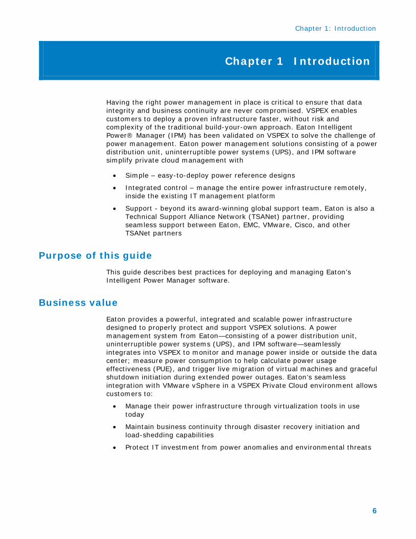
Configure Scan Settings 1. Click on the “System” section under “Settings”.
Chapter 3: IPM Set Up and Installation
17
Figure 11. Systems Settings Screen
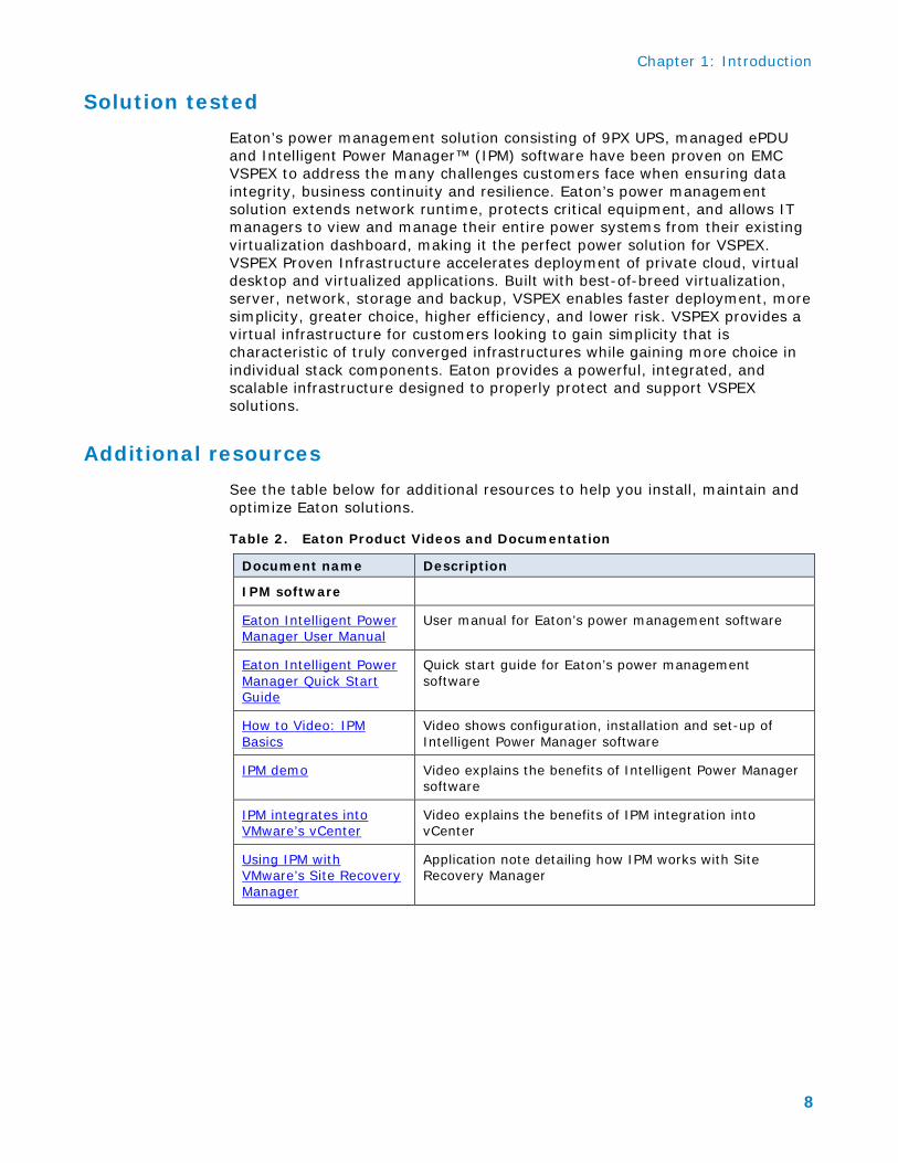
2. Click on “Edit scan settings” in the right-side navigation window.
Figure 12. Action List with Scan Settings Function

Chapter 3: IPM Set Up and Installation
18
3. Configure the XML, SNMPv1, and SNMPv3 settings to reflect the standard administrator username and password for all UPS/ePDU hardware within the infrastructure.
Ensure that “Automatic Scan” is enabled by checking the box.
Enter the standard UPS/ePDU username (Ex. “Admin”)
Enter the standard UPS/ePDU password (Ex. “rackadmin”)
Enter the SNMPv1 community name (Ex. “public”)
If needed, enter the SNMPv3 authentication information.
Click “Save” to continue.
Figure 13. Edit Scan Settings Screen
Establish Node Access to IPM Once the scans are complete, you will now need to ensure access is enabled for each node. This is required for IPM to be able to push information back to the cards.
1. Make visible the “Access” column
Hover the mouse over any column header to expose the column menu drop-down icon.
Click on the down arrow to access the menu.
Check the box beside “Access”.
You will now be able to see which devices are linked correctly and which still need attention.

Chapter 3: IPM Set Up and Installation
19
Figure 14. Node Access Column
2. Select the nodes that need to be updated. Then, click on “Set node access parameters”.
Figure 15. Set Node Access Parameters Screen
3. Type the username and password for the network cards.
Username: Admin Password: rackadmin Click “Save” to store values
Figure 16. Access Parameters Login Screen

Chapter 3: IPM Set Up and Installation
20
4. Once access has been correctly established with each node on the list, the list will look something like this:
Figure 17. Node List Screen
Change the Administrator Password 1. Click on “User List” in the Views navigation pane.
Figure 18. Views Screen on Navigation Page
2. Click on the “admin” user profile under the user list in the center display window.
Figure 19. User List Profile Screen

Chapter 3: IPM Set Up and Installation
21
3. Click on “Edit user” in the right-side control panel.
Figure 20. Edit User Actions
4. Enter and re-enter a new administrator password, then click “Save” to continue.
Figure 21. Edit User Screen
Create a New User 1. Click on “User List” in the Views navigation pane. See Figure 18.
2. Click on “Add user” in the right-side control panel. See Figure 20.
3. Define the user’s profile by entering the following:
A login name
A password and password confirmation
A profile level
− The “Admin” profile has full read/write access
− the “User” profile has read-only access
Then click “Save” to store the user
Figure 22. Add User Screen

Chapter 3: IPM Set Up and Installation
22
Set Up Pop-Up Notifications 1. Click on “Actions” in the Views navigation pane. See Figure 18.
2. Click on the pre-configured “Notification” action in the center actions pane.
Figure 23. Actions Pane
3. Click on “Edit selected action” in the right-side control panel.
Figure 24. Actions List
4. For “Event Criticalities”, leave only warning (yellow exclamation) and critical (red exclamation) checked. Click “Save” to continue.
Figure 25. Edit Action Screen
Note: for an unmonitored server installation, uncheck the box labeled “Action active”. No one will see these notifications on an unmonitored server.

Chapter 3: IPM Set Up and Installation
23
Setup Email Notifications 1. Click on “Actions” in the Views navigation pane. See Figure 18.
2. Click on the pre-configured “Email” action in the center actions pane. See Figure 23.
3. Click on “Edit selected action” in the right-side control panel. See Figure 24.
4. Configure a daily email to report all Warning Events from the day
Make sure only the box to the left of the “Yellow Exclamation” (Warning) is checked.
Click on the “Pencil” icon to the right of “Event categories” to open the “Edit event categories” pane.
− Check “All events” then click Save.
Figure 26. Edit Event Categories Screen
• Click the box beside “Action active”
• Name the action. Ex. “Daily System Warnings”.
• Specify “All Views” in the “From view” field.
• Specify “Email” as the action type.
• Enter the SMTP server information.
• The email Subject and Message is pre-defined to populate based on the device that triggers the alarm.
• Set the “Digest” to “Every day”.
• Click Save to continue
Figure 27. Edit Action Screen
5. Use the action copy feature to copy the previous email action to facilitate the creation of a second email action. See Figure 23.
Click on the “Daily System Warnings” action.
Click “Copy selected action”

Chapter 3: IPM Set Up and Installation
24
6. Enter a name for the new action.
Figure 28. Copy this Action Screen
7. Click on the newly created “Email on Critical Alarms” action in the
center actions pane.
Figure 29. Expanded Actions Screen
8. Click on “Edit selected action” in the right-side control panel. See
Figure 24.
9. Configure an immediate email notification for Critical Alarms. See Figure 26.
Make sure only the box to the left of the “Red Exclamation” (Critical) is checked.
Click on the “Pencil” icon to the right of “Event categories” to open the “Edit event categories” pane
− Check “Alarms” then click Save.
10. In the Edit Action screen (see Figure 27), do the following steps:
Click the box beside “Action active”
Specify “All Views” in the “From view” field.
Specify “Email” as the action type.
Enter the SMTP server information.

Chapter 3: IPM Set Up and Installation
25
The email Subject and Message is pre-defined to populate based on the device that triggers the alarm.
Set the “Digest” to “Every Minute”.
Click Save to continue.
Note: You can create as many email notifications as you like. These examples provide a basic level of notification coverage for the majority of IPM users.
IPM Plug-in for vCenter Installation Requirements Before registering IPM as a plug-in for vCenter Server, administrators must do the following:
• Install VMware vCenter Server and vSphere Client. Note that vCenter and IPM can be installed on the same server or on different ones. They can also be deployed on a physical server or a VM running on the VMware ESX/ESXi hypervisor.
• Install VMware administrative tools on every VM you will be managing via vCenter Server. IPM relies on these tools to shutdown VMs gracefully during power outages.
Install IPM plug-in for vCenter Server Enabling the Infrastructure Connectors Module
To enable the Infrastructures Connectors module for virtualization (administrator access):
1. From the left-side Views panel of the Eaton IPM main interface window, select the Settings > System menu item. The System page displays (see Figure 2).
Figure 30. System Settings Page

Chapter 3: IPM Set Up and Installation
26
2. Click Edit modules settings in the right panel. The Edit modules settings dialog box displays (see Figure 3).
Figure 31. Enable Infrastructure Connectors Setting for Virtualization
3. Ensure that the Infrastructure Connectors checkbox is selected
(checked).
4. Click Save.
When a user tries to add a connector by Settings->Infrastructure Connectors->Add a connector, the sequence if screens show options available, depending of the JRE prerequisite (see Figure 4). The unselectable options are italic and grayed-out.
• If any JRE is not installed on the system hosting Eaton IPM, only legacy virtualization connectors can be selected (legacy for VMware), but new connectors cannot be selected (New VMware vCenter, New VMware ESX/ESXi, NetApp Storage, or Cisco UCS Manager).
• If a JRE is installed on the system hosting Eaton IPM, new infrastructure connectors are available (see “JRE Prerequisites” on page 10 of the IPM User guide).

Chapter 3: IPM Set Up and Installation
27
Figure 32. Selectable and Non-selectable Connectors
Adding a vCenter Server Manager
To add a new VMware vCenter:
1. From the Add a Connector dialog, select New VMware vCenter from the Product drop-down list (see Figure 5). A second Add a connector dialog displays for your product connector selection.
Figure 33. Add a Connector Product Selection Dialog
Add identification information for the selected connector (see Figure 6).
• Product: Select New VMware vCenter from the drop-down list
• Hostname or IP address: Type VMware vCenter Hostname or IP address

Chapter 3: IPM Set Up and Installation
28
• Port: Type the port number
• Username: Type VMware vCenter Administrator Username
• Password: Type VMware vCenter Administrator Password
• vCenter Plugin: Select (check) the checkbox to install and configure the Eaton IPM Plug-in to vCenter
Figure 34. Add VMware vCenter
2. Click Save after the fields are updated. The VMware ESXi hosts are automatically added to the managed nodes.
Adding a VMware ESX/ESXi Hypervisor List
In the case where you do not have a vCenter server manager, add new VMware ESX/ESXi hosts individually.
To add a new VMware ESX/ESXi Hypervisor list:
1. From the Add a Connector dialog, select New VMware ESX/ESXi from the Virtualization drop-down list. A second Add a connector dialog displays for your product connector selection.
2. Add identification information for the selected connector (see Figure 7)
Product: VMware ESX/ESXi is already selected in the drop-down list.
Hostname or IP address: Type VMware ESX/ESXi Hostname or IP address
Username: Type VMware ESX/ESXi Administrator Username for the Administrator with admin rights on the ESXi
Password: Type VMware ESX/ESXi Administrator Password
3. Click Save after the fields are updated.

Chapter 3: IPM Set Up and Installation
29
Figure 35. Add VMware ESX/ESX)
VMware vCenter Server will now:
• Register IPM
• Create a new tab in vCenter labeled “Eaton Power Manager” (see Figure 8)
• Declare a series of new power -related events
• Create a new host alarm that is triggered when a power failure impacts this hypervisor
Figure 36. Eaton Power Manager tab on vCenter dashboard
In addition, IPM will:
• Build a comprehensive list of hypervisors in the VMware environment
• Create a new type of node that represents those hypervisors

Chapter 3: IPM Set Up and Installation
30
Using the IPM plug-in for VMware vCenter
Once the IPM plug-in for vCenter Server has been installed and registered, administrators can use it to view information about a host server’s power source, define shutdown settings for VMs and create or modify a variety of power-related events.
Viewing host server power information
1. In the “Views” pane, click “Node List” within the “Views” folder (see Figure 9).
2. Click “VMware host” (see figure 6). A list of VMware host devices appears in the “Node List” pane.
3. In the “Node List” pane, click the host device whose power information you wish to view. The information appears in the “Selection view” pane, under “Power Source”.
Figure 37. To view host server power information, click “Node List” in the “Views” pane, then click “VMware host” and then click a node in the “Node List” pane.
Defining and editing shutdown settings
1. In the “Views” pane, click “Nodes Settings” within the “Management” folder (see Figure 10). A list of power devices and hypervisors appears in the “Node List” pane.
2. In the “Node List” pane, click the hypervisor whose shutdown settings you wish to view or change (see Figure 10). Current shutdown settings for the selected hypervisor appear in the “Node configuration” pane, under “Shutdown settings”.

Chapter 3: IPM Set Up and Installation
31
3. To edit the shutdown settings, click the pencil icon next to the “Shutdown settings” label (see Figure 10). The “Shutdown Settings Configuration” dialog box appears (see Figures 11 and 12).
4. When you have finished defining or editing settings, click the “Apply” button.
Figure 38. To define or edit a shutdown setting, click “Nodes Settings” in the “Views” pane, click a node in the “Node List” pane and then click the pencil icon next to “Shutdown Settings”.

Chapter 3: IPM Set Up and Installation
32
Figure 39. The “Shutdown Settings Configuration” dialog box shows how we would configure server ESXi 2. This has maintenance enabled and shutdown disabled.
Figure 40. The “Shutdown Setting Configuration” dialog box shows how we would configure server ESXi 3. This has maintenance disabled and shutdown enabled.

Chapter 3: IPM Set Up and Installation
33
Triggering events in vCenter Server through IPM
Once vCenter Server and IPM are configured, a power outage to one of the host servers will:
• Send an event that triggers an alarm in the vCenter Server alarms page
• Put the server into maintenance mode
• Use vMotion to migrate all VMs on the physical host server onto a different physical host server that has not lost utility power
• Shutdown the hypervisor
Figure 41. ESXi host 2 configured for testing at EMC lab.
Figure 42. ESXi host 3 configured for testing at EMC lab.

Chapter 4: Testing the IPM Integration with VSPEX
34
Chapter 4 Testing the IPM Integration with VSPEX
The following tests focus on individual features, functionalities and operational behavior of IPM to ensure that the software corresponds to its specifications.
Test Results Summary Table 5. IPM Integration with VSPEX Test Results Summary
Pre-Test Conditions
• IPM software and IPM plugin for vCenter installed • Eaton 9PX UPS connected to a breaker • Test environment is installed and configured prior to
test execution • Refer to Appendix A for the pre-installation checklist
Test Procedure
To test, turn off a power outlet for 10 minutes and verify that the UPS signals IPM that it detects a power outage. At the defined length of power disruption, IPM will perform the operation being tested as listed above. Keep the power off while IPM finishes going into maintenance mode and shutdown mode. Testing duration is 15 minutes
Comments
Needed to resolve two issues to complete testing: • Place ESXi 2 and ESXi 3 into a cluster (see Figure 43) • Switch the breakers off one at a time (see Figures 43,
44 and 45)
Feature/ functionality to test:
IPM triggers alarms when power outage is detected.
Expected Results
Upon detection of a power outage by the UPS, IPM will send an event that triggers an alarm in the vCenter Server alarms page
Test Results
Pass. Figures 44, 45, 47, 48 and 50 show the UPS status alerts at the top and/or bottom of the screen. On battery condition alerts are shown on both top and bottom of the screen.
Chapter 4: Testing the IPM Integration with VSPEX
35
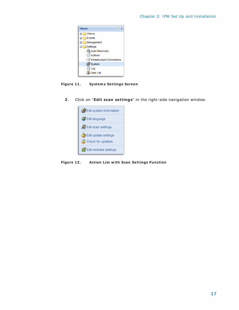
Feature/ functionality to test:
When loss of utility power is detected, IPM puts the server into maintenance mode.
Expected Results
Upon detection of a power outage by the UPS, IPM will put the server into maintenance mode.
Test Results:
Pass. Figure 46 shows ESXi 2 server entering maintenance mode when UPS 172.30.100.4 detected loss of utility power and went on battery. Figure 47 shows ESXi 2 server exiting maintenance mode when UPS 172.30.100.4 went back to utility power.
Feature/ functionality to test:
IPM triggers live migration for virtual machines during power outages
Expected Results
Upon detection of a power outage by the UPS, IPM will use vMotion to migrate all VMs on the physical host server onto a different physical host server that has not lost utility power.
Test Results:
Pass. Figure 44 shows UPS 172.30.100.4 and UPS 172.30.100.5 on battery power causing VM migration of ESXi 2 server. Figure 45 shows UPS 172.30.100.4 on battery power which triggered VM migration of ESXi 2 server. Figure 47 displays a VM cluster called Test 1 migrating when ESXi 2 server entered maintenance mode. Figure 48 shows Test 1 VM migration completed.
Feature/ functionality to test:
Gracefully shut down servers in clusters during an extended power outage.
Expected Results
Upon detection of a power outage by the UPS, IPM will shut down the hypervisor.
Test Results:
Pass. Figure 48 displays power lost to UPS172.30.100.5 which started the IPM timer to shutdown host 3 server. Figure 49 shows UPS 172.30.100.5 on battery and shutdown of host 3 server initiated. Figure 50 displays utility power returned to UPS 172.30.100.5 and host 3 server shutdown initiation as being completed.
Set Up Notes We took a few tries before we got the system synced between the EMC lab and the actual test case. We had two issues to resolve: one is that we needed to place ESXi 2 and ESXi 3 into a cluster. The second is that we needed to switch the breakers off one at a time.
As you can see in Figure 15, ESXi 3 was off and we tried to place ESXi 2 into maintenance mode. The system stalled because the hosts were not set up in a cluster.
Chapter 4: Testing the IPM Integration with VSPEX
36
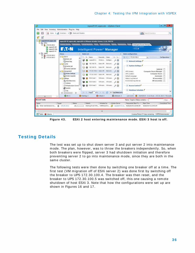
Figure 43. ESXi 2 host entering maintenance mode. ESXi 3 host is off.
Testing Details The test was set up to shut down server 3 and put server 2 into maintenance mode. The plan, however, was to throw the breakers independently. So, when both breakers were flipped, server 3 had shutdown initiation and therefore preventing server 2 to go into maintenance mode, since they are both in the same cluster.
The following tests were then done by switching one breaker off at a time. The first test (VM migration off of ESXi server 2) was done first by switching off the breaker to UPS 172.30.100.4. The breaker was then reset, and the breaker to UPS 172.30.100.5 was switched off, this one causing a remote shutdown of host ESXi 3. Note that how the configurations were set up are shown in Figures 16 and 17.

Chapter 4: Testing the IPM Integration with VSPEX
37
Figure 44. Test showing UPS 172.30.100.4 and UPS 172.30.100.5 on battery power causing VM migration off of ESXi 2 server and ESXi 3 host exiting standby mode.
Figure 45. Test 1 showing UPS 172.30.100.4 on battery power causing VM migration off of ESXi 2 server and ESXi 3 host exiting maintenance mode.

Chapter 4: Testing the IPM Integration with VSPEX
38
The recent task shown below is from the prior TEST 1 migration. The rest of the screen shot shows host 2 being powered by the battery. The time stamp from the prior task was 4:10:18.
Figure 46. Figure 1. Test showing VM called Test 1 migrating with server ESXi 2 on battery.
Virtual machine migration – server ESXi 2 on battery, entered maintenance mode, VM called TEST 1 is migrating. Time stamp of 4:12:55, this time lapse was due to the timer in IPM that waited 60 seconds before placing ESXi host 2 into maintenance mode.

Chapter 4: Testing the IPM Integration with VSPEX
39
Figure 47. ESXi host 2 exited maintenance mode when UPS 172.30.100.4 went back on utility power.
Exit maintenance mode – UPS 172.30.100.4 is back on utility, alarm at bottom says “end of UPS shutdown imminent alarm”’ so ESXi host 2 has exited maintenance mode. Time stamp 4:15:06 for when power was restored to UPS (reset breaker on UPS 172.30.100.4) and alarm from UPS is cleared, therefore exit of maintenance mode.

Chapter 4: Testing the IPM Integration with VSPEX
40
Figure 48. Power lost to UPS 172.30.100.5, starts timer for when to shut down host 3. The time stamp of 4:15:06 was from clearing the last test.
Figure 49. Initiate host shutdown, UPS 172.30.100.5 selected, on the right side, note UPS on battery and initiation of host shutdown (host 3). The time stamp of 4:16:56 gave time for the IPM timer to initiate the host shutdown process.

Chapter 4: Testing the IPM Integration with VSPEX
41
Figure 50. UPS power has returned from utility, we did not wait long enough for host ESXi 3 to shut down then promptly reset breaker. You can see the latest time stamp was 4:16:56.

Appendix A: IPM Pre-Installation Checklist
42
Appendix A IPM Pre-Installation Checklist
Verify the following steps before installing IPM. Consult the ReadMe file for up-to-date system requirements.
Table 6. IPM Pre-Installation Checklist
Action Checked
Hardware
Verify that the UPS is connected to a power source.
Verify that the equipment to be protected are connected to the UPS or ePDU connected to the UPS/
Ensure that the network management card is installed in the UPS
Verify presence of these systems. IPM installation requires • Systems hosting the Eaton IPM • Systems that display the Web-based graphical user interface (GUI)
Operating Systems
Check the operating system. IPM can be installed on Microsoft® Windows 2000, Microsoft® Windows XP®, Microsoft® Windows Vista® 7, Microsoft® Windows 7 and 8, and on Microsoft® Windows Server® 2003, 2008 (including R2 revision), and 2012. For better performances with multiple nodes, Eaton recommends a Microsoft® Windows Server® OS (that does not have the limitation of 10 simultaneous network connections) To avoid network or serial port access conflicts, do not install the Eaton IPM on a machine that also hosts: • Network management system, such as HP OpenView® or CA
Unicenter® • Eaton Intelligent Power Protector (IPP) • Eaton Enterprise Power Manager • Eaton Network Shutdown Module • Network Management Proxy • Eaton UPS Management Software (This is the previous Eaton
software for managing UPSs. If you were using it previously, remove it before installing the new Eaton IPM software.)

Appendix A: IPM Pre-Installation Checklist
43
Action Checked
System that Displays the Web-based GUI
Check the system that displays the Web-based GUI. The IPM graphical interface can be accessed remotely using a simple Web browser. Access to this interface can be secured through Secure Socket Layer (SSL) connection and is also secured through login and password. • The Eaton IPM graphical interface has been tested with: • Google® Chrome™ • Mozilla Firefox® • Microsoft® Internet Explorer® (IE) version 7 and later NOTE: For optimal performance, Google Chrome or Firefox is recommended. For good performance, IE version 9 and later is recommended. IE6 performance is not optimal.
Java Runtime Environment (JRE) Prerequisites
Check JRE prerequisites. For all features correlated to the infrastructure connector (like VMware, UCS, NetApp) a JRE must be installed on the system hosting Eaton IPM (see “JRE Installation” on page 15 of the Eaton IPM Users Guide). If this prerequisite is not installed, only virtualization features are available, such as the legacy API for VMware connectors.
JRE Installation
The installation of the JRE is Operating System platform-dependent. All new Eaton components have been developed and tested for the Java version 1.6 or later. After installing the correct JRE, the IPM must be reloaded, to take account this new environment.
User Accounts
Ensure that the installation account is an account with local administrator rights.
Network
To configure e-mail alerts, the alert service needs access to the Mail Server. Confirm the following details for the Server hosting the alert agent: • The Server has a connection with the Mail Server • The host name of the Mail Server