eaton® intelligent power manager ® (ipm) infrastructure...
TRANSCRIPT

Eaton® Intelligent Power Manager ® (IPM) Infrastructure
User guide
Rev 1.1 02/28/2018


1 Class A EMC Statements
1.1 FCC Part 15This equipment has been tested and found to comply with the limits for a Class A digital device, pursuant to part 15 of the FCC Rules. These limits are designed to provide reasonable protection against harmful interference when the equipment is operated in a commercial environment. This equipment generates, uses, and can radiate radio frequency energy and, if not installed and used in accordance with the instruction manual, may cause harmful interference to radio communications. Operation of this equipment in a residential area is likely to cause harmful interference, in which case the user will be required to correct the interference at his own expense.
1.2 ICES-003This Class A Interference Causing Equipment meets all requirements of the Canadian Interference Causing Equipment Regulations ICES-003.
Cet appareil numérique de la classe A respecte toutes les exigences du Reglement sur le matériel brouilleur du Canada.
1.3 EN 62040-2Some configurations are classified under EN 62040-2 as “Class-A UPS for Unrestricted Sales Distribution.” For these configurations, the following applies:
1.3.1 WARNINGThis is a Class A-UPS Product. In a domestic environment, this product may cause radio
interference, in which case the user may be required to take additional measures.

2 Requesting a Declaration of Conformity Units that are labeled with a CE mark comply with the following harmonized standards and EU directives:
• Harmonized Standards: IEC 61000-3-12
• EU Directives:
73/23/EEC, Council Directive on equipment designed for use within certain voltage limits
93/68/EEC, Amending Directive 73/23/EEC 89/336/EEC, Council Directive relating to electromagnetic compatibility
92/31/EEC, Amending Directive 89/336/EEC relating to EMC
The EC Declaration of Conformity is available upon request for products with a CE mark.
For copies of the EC Declaration of Conformity, contact:
Eaton Power Quality Oy
Koskelontie 13
FIN-02920 Espoo
Finland
Phone: +358-9-452 661
Fax: +358-9-452 665 68

3 Special SymbolsThe following are examples of symbols used on the UPS or accessories to alert you to important information:
RISK OF ELECTRIC SHOCK - Observe the warning associated with the risk of electric shock symbol.
-----------------------------------------------------------------------------------------------------------------------------------------------
CAUTION: REFER TO OPERATOR'S MANUAL - Refer to your operator's manual for additional information, such as important operating and maintenance instructions.
-----------------------------------------------------------------------------------------------------------------------------------------------
This symbol indicates that you should not discard the UPS or the UPS batteries in the trash. This product contains sealed, lead-acid batteries and must be disposed of properly. For more information, contact your local recycling/reuse or hazardous waste center.
-----------------------------------------------------------------------------------------------------------------------------------------------
This symbol indicates that you should not discard waste electrical or electronic equipment (WEEE) in the trash. For proper disposal, contact your local recycling/reuse or hazardous waste center.

Eaton is a registered trademark of Eaton Corporation or its subsidiaries and affiliates.
Phillips and Pozidriv are a registered trademarks of Phillips Screw Company.
National Electrical Code and NEC are registered trademarks of National Fire Protection Association, Inc.
Microsoft®, Windows®, and Windows Server® are either registered trademarks or trademarks of Microsoft Corporation in the United States and/or other countries.
UNIX® is a registered trademark of The Open Group.
Linux® is the registered trademark of Linus Torvalds in the U.S. and other countries.
VMware is a registered trademark or trademark of VMware, Inc. in the United States and/or other jurisdictions.
Google™ is a trademark of Google Inc.
All other trademarks are properties of their respective companies.
©Copyright 2017 Eaton Corporation. All rights reserved.
No part of this document may be reproduced in any way without the express written approval of Eaton Corporation.

IPM Infra User Guide P-164000637 —Rev 1.1 02/28/2018 Table of Contents - 7
4 Table of Contents
1 Class A EMC Statements 31.1 FCC Part 15 .......................................................................................................................................... 31.2 ICES-003............................................................................................................................................... 31.3 EN 62040-2 ........................................................................................................................................... 31.3.1 WARNING ........................................................................................................................................... 3
2 Requesting a Declaration of Conformity 4
3 Special Symbols 5
4 Table of Contents 7
5 General information 105.1 Initial setup & configuration ................................................................................................................. 105.1.1 Initial commissioning ......................................................................................................................... 105.1.1.1 Connecting the unit to the network...................................................................................................105.1.1.2 Login Wizard ....................................................................................................................................105.2 Alarms Management ........................................................................................................................... 145.2.1 Introduction........................................................................................................................................ 145.2.2 Alarm Lifecycle .................................................................................................................................. 165.3 Asset Management ............................................................................................................................. 185.3.1 Asset Management from the User Interface...................................................................................... 215.3.1.1 Asset creation...................................................................................................................................215.3.1.2 Edit existing asset ............................................................................................................................235.3.1.3 Delete an Existing Asset...................................................................................................................245.3.2 T&H Sensors Management ............................................................................................................... 245.3.3 ePDU G3 Daisy Chaining.................................................................................................................. 255.4 User Management............................................................................................................................... 275.5 Xtreme Support Process ..................................................................................................................... 275.6 Supported Power Chain Topologies .................................................................................................... 285.7 SSL Certificate Management............................................................................................................... 305.7.1 How to Set Up a Valid SSL Certificate............................................................................................... 305.7.1.1 Step 1: connect to IPC as admin and generate a Certificate Signing Request (CSR).....................305.7.1.2 Step 2: After successful generation of the keys and CSR, you should transfer the bios2048.csr file
created above to your Microsoft CA system. Then submit the CSR for signing and the save the new fresh signed certificate. ....................................................................................................................31
5.7.1.3 Step 3: Applying the certificate to the IPC3000 device ....................................................................315.7.1.4 Step 4: Export your root certificate and install it on the PCs client...................................................315.8 IPC3000 Hardware Specifications....................................................................................................... 325.8.1 Technical Specfications ..................................................................................................................... 325.8.2 I/O HW Features: .............................................................................................................................. 335.8.2.1 Front panel: ......................................................................................................................................335.9 Cybersecurity ...................................................................................................................................... 35
6 Contextual Help 366.1 Dashboard View .................................................................................................................................. 366.2 Power Chain View ............................................................................................................................... 366.3 Rack View............................................................................................................................................ 376.4 UPS View ............................................................................................................................................ 426.5 Environmental View............................................................................................................................. 436.6 Alarms View......................................................................................................................................... 44
8 - Table of Contents IPM Infra User Guide P-164000637 —Rev 1.1 02/28/2018
6.7 Asset Management View..................................................................................................................... 456.7.1 Main actions ...................................................................................................................................... 466.7.1.1 Auto Discovery .................................................................................................................................466.7.1.2 Upload CSV file ................................................................................................................................486.7.1.3 Add New Asset .................................................................................................................................486.7.1.4 Export Assets ...................................................................................................................................506.7.1.5 Delete Asset .....................................................................................................................................506.7.2 Asset list statistics and report............................................................................................................ 516.7.2.1 Asset List ..........................................................................................................................................516.8 Setting Views....................................................................................................................................... 526.8.1 Alarms settings view.......................................................................................................................... 526.8.1.1 Data Center Alarm Settings..............................................................................................................536.8.1.2 UPS Alarm Settings..........................................................................................................................536.8.1.3 Row Alarm Settings ..........................................................................................................................546.8.1.4 Rack Alarm Settings .........................................................................................................................546.8.1.5 PDU Alarm Settings..........................................................................................................................556.8.2 DC Layout settings view.................................................................................................................... 556.8.3 General settings view ........................................................................................................................ 566.8.4 Network settings view........................................................................................................................ 576.8.5 Preferences settings view ................................................................................................................. 586.9 Feedback Tool ..................................................................................................................................... 586.10 Login page........................................................................................................................................... 596.11 Status dashboard ................................................................................................................................ 59
7 Troubleshooting 617.1 Factory Reset ...................................................................................................................................... 617.2 Send debug information through the feedback tool ............................................................................ 617.3 Using the diagnostic tool ..................................................................................................................... 617.3.1 Examples of usage:........................................................................................................................... 627.4 Using the Service port ......................................................................................................................... 62

EN 62040-2
IPM Infra User Guide P-164000637— Rev 1.1 02/28/2018 Table of Contents - 9
Initial setup & configuration
10 - General information IPM Infra User Guide P-164000637 —Rev 1.1 02/28/2018
5 General information
5.1 Initial setup & configuration
5.1.1 Initial commissioning
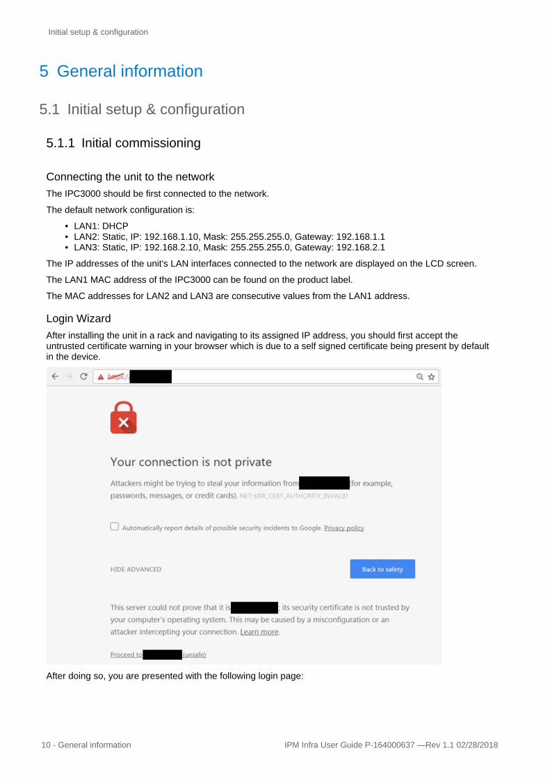
Connecting the unit to the networkThe IPC3000 should be first connected to the network.
The default network configuration is:
• LAN1: DHCP • LAN2: Static, IP: 192.168.1.10, Mask: 255.255.255.0, Gateway: 192.168.1.1 • LAN3: Static, IP: 192.168.2.10, Mask: 255.255.255.0, Gateway: 192.168.2.1
The IP addresses of the unit's LAN interfaces connected to the network are displayed on the LCD screen.
The LAN1 MAC address of the IPC3000 can be found on the product label.
The MAC addresses for LAN2 and LAN3 are consecutive values from the LAN1 address.
Login WizardAfter installing the unit in a rack and navigating to its assigned IP address, you should first accept the untrusted certificate warning in your browser which is due to a self signed certificate being present by default in the device.
After doing so, you are presented with the following login page:

Initial setup & configuration
IPM Infra User Guide P-164000637— Rev 1.1 02/28/2018 General information - 11
As you are logging into the IPM Infra for the first time, you must enter the factory default username andpassword which are set to:
Username = adminPassword = admin
As can be seen in the image below, the password details are obscured from view so please ensure to enter the password carefully and correctly.
At first login, the system requires that you change the default admin password.
• The user is presented with the message shown below requesting the current admin password ("admin") and the new password.
• Follow the password format recommendations on the tooltip in order to define a secure password;• A secure password is mandatory. • Click "Continue"
After changing the password, the user is presented with the License Agreement.
Please read it and accept it to continue.
Please refer to the Legal Information below for more information.

Initial setup & configuration
12 - General information IPM Infra User Guide P-164000637 —Rev 1.1 02/28/2018
On the next page, the user is presented with is the network configuration settings.
The user must confirm the network configuration settings are correct. If no changes are necessary, the user may proceed to the next step, by clicking on Continue.
NOTE If changes are made on the network configuration page, the user will be automatically logged out when all the steps of the wizard are complete in order to restart the network services.
Initial setup & configuration
IPM Infra User Guide P-164000637— Rev 1.1 02/28/2018 General information - 13
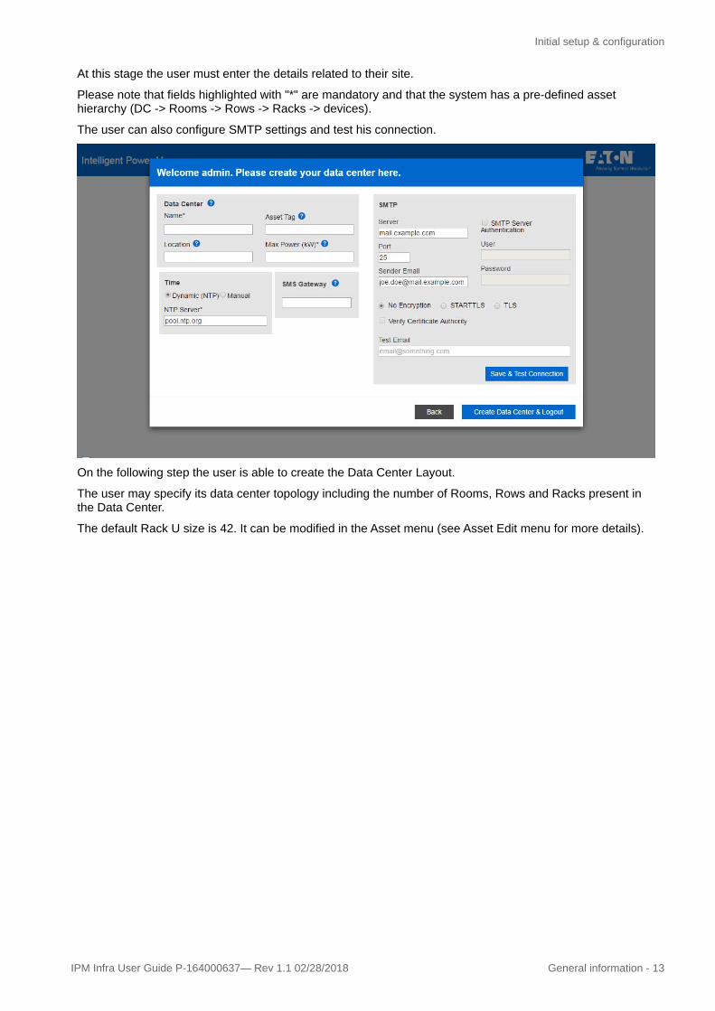
At this stage the user must enter the details related to their site.
Please note that fields highlighted with "*" are mandatory and that the system has a pre-defined asset hierarchy (DC -> Rooms -> Rows -> Racks -> devices).
The user can also configure SMTP settings and test his connection.
On the following step the user is able to create the Data Center Layout.
The user may specify its data center topology including the number of Rooms, Rows and Racks present in the Data Center.
The default Rack U size is 42. It can be modified in the Asset menu (see Asset Edit menu for more details).

Alarms Management
14 - General information IPM Infra User Guide P-164000637 —Rev 1.1 02/28/2018
On this tool the user will find that for every Room created, a Row and Rack are also created automatically.
Finally, after saving all of the initial Data Center details, we are prompted to configure the Data Center.
There are two different ways to setup the infrastructure of the data center and define your assets:
1. Through a CSV file. This is an advanced configuration tool which will allow you to create your data center's topology freely but can lead to configuration issues if misused. It is not advised to use it at first time if you don't have already a correct CSV file or help from an experienced service consultant.
2. A graphical tool using the web interface. This will allow you to easily create your data center's topology. It is the recommended option.
5.2 Alarms Management
5.2.1 IntroductionIPM Infrastructure offers to the user the capability of managing alerts.
NOTE The data center layout can be updated later on from the Settings page.
NOTE If network parameters have been changed, the user will be automatically logged out after this screen and will be required to login to start a new session.

Alarms Management
IPM Infra User Guide P-164000637— Rev 1.1 02/28/2018 General information - 15
An event can be defined as any detectable or discernible occurrence that has significance for the management of the IT infrastructure or delivery of an IT service as well as the evaluation of the impact a deviation might have on the infrastructure or service. Any event must be made visible to the user.
There are two types of alarm currently existing in the application:
• Alarms are generated at the IPM Infrastructure level, using the user defined or automatically imported thresholds (see Setting Thresholds chapter for reference)
• Alarms acquired directly from the monitored power devices (ePDUs, UPS)
Independent on the alarm type, any alarm has a set of attributes and follows a certain lifecycle.
The severity types are predefined priority levels for alarms related to particular elements and systems within the data center. All alarms need to be well defined and categorized depending on the impact caused to the business. However incorrectly defining alarms, such as under-prescribing priority levels can have serious consequences, not setting the appropriate priority level may result in a business impacting issue that is costly to resolve at too late a stage.
Over-prescribing the priority level, can cost a company more in the long run, costs such as remote hands work, overtime and call-out charges for on-call engineers.
Below are examples of how data center priority levels could be set:
• P1 (Priority 1): Absolute Highest Priority - Directly impacting business• Any alarm related to the data center power chain that directly negatively impacts on
redundancy should always fall into this category• Any alarm related to IT Network Connectivity that is directly negatively impacting business
should fall into this category• Any alarm related to IT Systems that is directly negatively impacting business should also fall
into this category• Any alarm related to main chillers, pumps, AHU (Air Handling Units) and CRAC (Computer
Room Air Conditioning) units that are directly impacting on the cooling of the data center and will therefore directly impact the business
• Any alarm related to smoke alarms, fire alarms, fire suppression systems.• Any alarm related to data center physical security systems.
• P2 (Priority 2): High Priority - Not yet impacting business but has potential to escalate quickly.• Alarms related to the data center power chain that have potential to impact redundancy soon,
but are not yet at the business critical level.• Alarms relating to IT Network Connectivity that has potential to become a business impacting
issue, but are not yet at the business critical level.• Alarms related to IT Systems that has potential to become a business impacting issue soon,
but are not yet at the business critical level.• Alarms related to main chillers, pumps, AHU (Air Handling Units) and CRAC (Computer Room
Air Conditioning) units that have potential to impact on the cooling of the data center soon, but are not yet at the business critical level.
• P3 (Priority 3): Medium Priority - Not impacting business but could become critical in the short term• Alarms related to the Data Center power chain that will not impact redundancy immediately, but
can negatively impact on performance, and have the potential to escalate into more serious issues.
• Alarms relating to IT Network Connectivity that will not impact business immediately, but can negatively impact on performance, and have the potential to escalate into more serious issues
• Alarms related to IT Systems that will not impact business immediately, but can negatively impact on performance, and have the potential to escalate into more serious issues.
• Alarms related to main chillers, pumps, AHU (Air Handling Units) and CRAC (Computer Room Air Conditioning) units that will not impact the cooling of the data center immediately, but can negatively impact on performance, and have the potential to escalate into more serious issues.
• P4 (Priority 4): Low Priority - Not impacting business but could become critical in the long term if left unaddressed.
• Alarms related to the Data Center power chain that will not impact redundancy immediately, but can negatively impact on performance, and have the potential to escalate into more serious issues if ignored long term.

Alarms Management
16 - General information IPM Infra User Guide P-164000637 —Rev 1.1 02/28/2018
• Alarms relating to IT Network Connectivity that will not impact business immediately but can negatively impact on performance and have the potential to escalate into more serious issues if ignored long term.
• Alarms related to IT Systems that will not impact business immediately but can negatively impact on performance and have the potential to escalate into more serious issues if ignored long term.
• Alarms related to main chillers, pumps, AHU (Air Handling Units) and CRAC (Computer Room Air Conditioning) units that will not impact the cooling of the Data Center immediately, but can negatively impact on performance and have the potential to escalate into more serious issues if ignored long term.
• P5 (Priority 5): Minimal Priority - Not impacting business but worth taking note of to be resolved in futures service/maintenance intervals.
• Alarms related to the Data Center power chain that are not impacting performance in any way, but will need to be resolved during maintenance periods.
• Alarms relating to IT Network Connectivity that will not impact business or performance, but will require resolution during prescribed downtime/maintenance periods
• Alarms related to IT Systems that will not impact business or performance, but will require resolution during prescribed downtime/maintenance periods.
• Alarms related to main chillers, pumps, AHU (Air Handling Units) and CRAC (Computer Room Air Conditioning) units that will not impact the cooling of the Data Center or its performance but will require resolution during prescribed downtime/maintenance periods.
In IPM Infra, the user can define such priority levels for each asset existing in the application. All alarms related to any asset will inherit the priority level of the asset and they will be treated accordingly.
5.2.2 Alarm LifecycleEvery alarm can go through several states, based on the user actions or system behavior. All of these states and the possible transitions between them are described below:
Active Acknowledged Archived
Active Ignore Silence Pause Work in Progress Resolved
Ack State Changes
Description Visible on UI
Notification Other
ACK-IGNORE
Means that the user has acknowledged the alarm but has not taken action. The system should log the user's response & stop sending email/sms alarms for this alarm to this user, but continue sending the alarms to any of the other users in the group who have not acknowledged the alarm (group management post-alpha).
No No Can be un-ignored manually
NOTE
Once the alarm is acknowledged into any of the states listed, it cannot be unacknowledged. An Acknowledged alarm can only be changed to another state of acknowledgement.

Alarms Management
IPM Infra User Guide P-164000637— Rev 1.1 02/28/2018 General information - 17
ACK-SILENCE
Means that the user has acknowledged the alarm and is taking action to resolve it. The system should log the user's response & stop sending alarms to this person and any other person in the group. The alarms remains visible in the system.
Yes No Can be un-silences manually
ACK-PAUSE
Means that the user has acknowledged the alarm and is waiting for external input (user info, maintenance window, part delivery, ...) prior to resolving it. The system should log the user's response & stop sending alarms to this person and any other person in the group. The alarm remains visible in the system.
Yes No Can be manually un-paused or automatically after a specified amount of time
ACK-WIP Means that the user has acknowledged the alarm and is currently classed as Work in Progress. The alarm remains visible in the system and continues to send out notifications at a specified time frequency depending on the priority/severity.
Yes Email or SMS sent at regular intervals while the alarm is still present, interval determined by priority/severity
If an alarm occurs on the system and is not acknowledged, the notification must be resent until the alarm is acknowledged into one of the states listed above.
Simplified Alarm Retry Table
critical p1 5 min
p2 15 min
p3
p4
p5
warning p1 1h
p2 4h
p3
p4
p5
info p1 8h
p2 24h

Asset Management
18 - General information IPM Infra User Guide P-164000637 —Rev 1.1 02/28/2018
5.3 Asset Management
How to use the CSV file for commissioningRight after the Setup Wizard, the software will propose you to Upload a CSV file.
If you prefer to use the Graphical tool, please click on "Cancel" and jump to the section "Asset Management from the User Interface".
If you have not already completed your CSV file in advance of the IPM Infra installation and you want to continue with asset configuration through CSV, you can simply export a copy of the CSV with all the information filled during the wizard steps. To do this just click on "Export Assets"

Asset Management
IPM Infra User Guide P-164000637— Rev 1.1 02/28/2018 General information - 19
All the remaining details relating to the devices installed in the Data Center must be entered into the CSV file. Please check the Appendix 2 about CSV. The CSV creation tool enables the user to complete the CSV file in a step-by-step manner and explains the relationship between the devices recorded.
Once the CSV file is created it will resemble the populated sample displayed below.
When you are done or if you already have a CSV file, you can upload it clicking on the "Choose File" button which will open a file browser in order to select your CSV file. Then click on "Upload" to import it in the system.
While the upload is being processed a dial indicates the progress of the activity.
In case of upload errors, they are returned to the user, specifying at which line the error occurred and some details about it;.

Asset Management
20 - General information IPM Infra User Guide P-164000637 —Rev 1.1 02/28/2018
In case only some CSV lines will be imported successfully, the message returned to the end user after the import will detail the import errors.
If the file upload is successful the user is given confirmation of the activity performed.
Import Errors
Error Condition Code
Method is not allowed 45
Content size is too big 53
File "assets" is missing 46
File "assets" has bad coding or bad format 47
Internal error (no connection to database, ... ) 42

Asset Management
IPM Infra User Guide P-164000637— Rev 1.1 02/28/2018 General information - 21
Mandatory columns are missing in the csv file 46
Load csv was success, but error occurred during configuration sending of asset change 42 notification. Consult system log.
42
Request document has invalid syntax. Cannot detect the delimiter, use comma (,), semicolon (;) or tabulator.
48
To view and scroll through the Asset Management page just click on the "Close" button, this will allow the user to interact with the Asset Management page.
The details submitted via CSV upload can now be viewed on the Asset Management page in a simplified spreadsheet format.
You can edit the data center assets using the CSV file as follows:
1. Press the "Export Assets" button2. Update the downloaded CSV file3. Re-upload the CSV file using the "Upload CSV File" button.
5.3.1 Asset Management from the User InterfaceBesides the possibility of managing assets through the CSV file, the user can manage his assets from the Web User Interface. The possible operations for assets are create, edit and delete.
Asset creationAll asset management operations are available in the Asset Management page.
NOTE
In version 1.0.0, the data center objet may not be deleted from the UI.

Asset Management
22 - General information IPM Infra User Guide P-164000637 —Rev 1.1 02/28/2018
1 file:///C:/Users/C9903574/Downloads/P-164000637_Eaton%20%20Intelligent%20Power%20Manager%20(IPM)%20Infrastructure%20Initial%20Login%20and%20Operation%20User%20Guide_May%20Edit.docx#page24
2 file:///C:/Users/C9903574/Downloads/P-164000637_Eaton%20%20Intelligent%20Power%20Manager%20(IPM)%20Infrastructure%20Initial%20Login%20and%20Operation%20User%20Guide_May%20Edit.docx#page24
From the Dashboard, the user can access the page from the top menu Asset management. All possible operations on assets are accessible through the page menu:
In order to create a new asset, the user must use the button "Add New Asset". A pop up window will appear in order to introduce the basic asset information.
Before proceeding with adding assets to your system, please consider the below comments:
1. Create the appropriate Input Power topology of your data center. See the different recommended topologies available in the Appendix 1. There is a specific Power Chain in our system called "Input Power Chain". These are the power devices (Feed, Genset, stand-alone UPS) which provide power to your Data center. In order to define a device as being part of the Input Power Chain, you need to set its location as "data center".
2. After defining the input power chain of the data center, we recommend to proceed to the creation of all rack mounted power devices (rack mounted UPS, rack PDUs) in order to complete the power chain down to the rack device level.
3. For adding sensors to the asset list, there is a dedicated "Sensor" Section in this User Guide.4. For adding daisy chained rack PDUs to the asset list Refer to Chapter 2, “ePDU G3 Daisy Chaining”
on1 page 18.25. For the Eaton power devices communication with the IPC3000, the user has to enable SNMP v1
protocol from the Web interface of the ePDU. This is mandatory in order to get all data. Please don't forget to add SNMP v1 community in the Settings page if the ePDU community name is different than "public".
All fields marked with * are mandatory.
Based on the selected asset type, additional fields with other information will appear where the user can input extra device information (e.g. for ePDU below).
Asset Management
IPM Infra User Guide P-164000637— Rev 1.1 02/28/2018 General information - 23
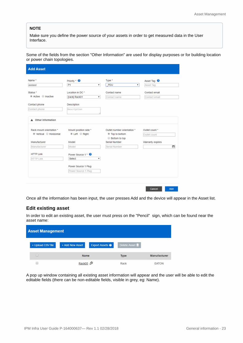
Some of the fields from the section "Other Information" are used for display purposes or for building location or power chain topologies.
Once all the information has been input, the user presses Add and the device will appear in the Asset list.
Edit existing assetIn order to edit an existing asset, the user must press on the "Pencil" sign, which can be found near the asset name:
A pop up window containing all existing asset information will appear and the user will be able to edit the editable fields (there can be non-editable fields, visible in grey, eg: Name).
NOTE
Make sure you define the power source of your assets in order to get measured data in the User Interface.

Asset Management
24 - General information IPM Infra User Guide P-164000637 —Rev 1.1 02/28/2018
Delete an Existing AssetThe user can delete assets present in the Asset list except for the Data Center.
In order to delete an asset, it must not have any child devices from a power chain topology or from a location perspective. All child assets must be deleted prior to deletion of a parent asset.
5.3.2 T&H Sensors ManagementThe T&H sensors are managed as standard assets. Therefore, the user can create and edit a sensor from the asset management page or through the CSV file and he can delete any sensor from the asset management page.
IPM Infra can monitor sensors:
• connected directly to the IPC3000 (via the ) or to the Eaton power devices (UPS, ePDU). Please find more details about the TH ports in the Hardware Specification chapter.
In order to define where the sensor is connected, the user must specify the "location port" and the "Location in DC" fields.
The location port:
• TH1…4 for sensors connected directly to the IPC3000• 0 for sensors connected to Eaton power
NOTE
You will need to create the device where the EMP001 will be plugged before creating the sensor itself. If you want to plug the sensor on your IPC3000, it has been created automatically when you first connected to the graphical user interface. In case it would have been deleted, you can recreate it by adding a new asset of subtype "Rack Controller" which will represent the IPC3000.

Asset Management
IPM Infra User Guide P-164000637— Rev 1.1 02/28/2018 General information - 25
Sensor Location port Device Physical port (RS232, T&H)
TH1 9
TH2 10
TH3 11
TH4 12
Any sensor is mounted physically in a rack, therefore the user must specify the rack. He can do it through the field "Logical asset". Once assigned to a rack, the values returned by the sensor will be used for computing the average temperature and humidity for that specific rack.
The temperature and humidity values for rows are computed as averages of values of racks contained in the row, averages being propagated to the DC level.
5.3.3 ePDU G3 Daisy ChainingEaton ePDU G3 offering can manage Daisy Chain configuration (up to 8 ePDUs connected in parallel, with only one IP address required to manage all of them).
According to its topology, the user must first configure the Daisy Chain on the ePDU side from the LCD (refer to Eaton G3 user manual for more information if needed), and define which ePDU is the host.

Asset Management
26 - General information IPM Infra User Guide P-164000637 —Rev 1.1 02/28/2018
On the IPC side, the user has to create a new ePDU asset with the type "EPDU", fill all mandatory fields.
This operation has to be done for all ePDUs in Daisy Chain configuration (Host and all devices connected to the host).
ePDU LCD Configuration IPC Asset Daisy Chain Menu
0 (Host) 1 - Host
IMPORTANT NOTE
As for the ePDU in Single mode, the user has to enable SNMP v1 protocol from the Web interface of the ePDU. This is mandatory to get data from the ePDUs. Don't forget to add SNMP v1 community in the Settings menu if the ePDU community name is different than "public".
NOTE
The user has to check that the configuration defined in the rack is matching the configuration defined on the ePDU power Chain topology, see table below:

User Management
IPM Infra User Guide P-164000637— Rev 1.1 02/28/2018 General information - 27
1 (Device) 2
2 (Device) 3
3 (Device) 4
4 (Device) 5
5 (Device) 6
6 (Device) 7
7 (Device) 8
5.4 User ManagementThe current version of IPM Infra provides two predefined users:
• Admin user: who has access to all operations (monitor, commissioning, settings)• Monitor user: who can access only the Dashboard and user preferences
Default passwords:
Login Password
admin admin
Monitor monitor
Both users can change the password from the Settings page, in the Preferences section.
5.5 Xtreme Support ProcessIPM Infrastructure is intended to grow to support many third party devices, and especially Simple Network Management Protocol (SNMP) enabled ones. If you would like to request support for a specific SNMP device that is not yet supported, please follow this support process in this section.
NOTE
It is strongly recommended to change the default passwords.
NOTE
Password strength requirements include:
• Minimum of 8 characters• At least 1 special character• At least 1 digit

Supported Power Chain Topologies
28 - General information IPM Infra User Guide P-164000637 —Rev 1.1 02/28/2018
3 mailto:[email protected] mailto:[email protected]
Procedure to run the tool:
1. Connect to your IPM Infrastructure using SSH, using the "admin" account2. Run " fty-device-scan <IP address of the device> <your email address>"
Example: fty-device-scan 192.168.0.10 [email protected]
3. Send the archive received by mail to [email protected].
If possible, provide as much information on the device as possible in your mail, such as:
• Mentioning the type of device, exact manufacturer and model names• Attaching the MIBs related to the device, or pointing the online versions, if available• Any other information that you may find suitable.
Information and directions will be provided back to you shortly by mail to add support for your device.
5.6 Supported Power Chain TopologiesList of supported configurations for the input power infrastructure:
1. Zero resilience configuration with 1 main feed directly powering the infrastructure.
2. Minimal resilience configuration with 1 main feed and 1 UPS protecting the infrastructure.
NOTE
The product embeds a tool that can be used to extract information from devices that are not yet supported.This tool can be used through Secure Shell (SSH) connection.

Supported Power Chain Topologies
IPM Infra User Guide P-164000637— Rev 1.1 02/28/2018 General information - 29
3. Minimal resilience configuration with 1 main, 1 GenSet, 1 ATS and a rack mounted UPS (instead of astandalone UPS) installed in the white space with the IT devices.
4. Minimal resilience configuration with 2 main feeds (Utility A & Utility B), an ATS and a rack mounted UPS (instead ofa standalone UPS) installed in the white space with the IT devices.
5. N configuration (Tier I) with 1 main, 1 GenSet, 1 standalone UPS installed in the grey space.
6. N configuration (Tier I) with 2 main (Utility A & Utility B), 1 ATS and 1 standalone UPS installed in the grey space.
7. N+1 (Tier II) Smart grid Configuration: 1 Mains, 2 Gen Sets for additional redundancy, and 2 UPS.

SSL Certificate Management
30 - General information IPM Infra User Guide P-164000637 —Rev 1.1 02/28/2018
8. N+1 (Tier II) Smart grid Configuration: 2 Mains (Utility A & Utility B), 1 Gen Set for additional redundancy, and 2 UPS.
5.7 SSL Certificate Management
5.7.1 How to Set Up a Valid SSL CertificateThe following is an example for how to install a valid SSL certificate signed by Microsoft Certification Authority 2008R2
Step 1: connect to IPC as admin and generate a Certificate Signing Request (CSR)# login as admin
:; ssh admin@eaton-rc-002085ec0072
# generate a new private key and a the CSR
:; openssl req -new -newkey rsa:2048 -nodes -sha256 \
> -keyout bios2048.key -out bios2048.csr
Generating a 2048 bit RSA private key
.........+++
................................+++
writing new private key to 'bios2048.key'
-----
You are about to be asked to enter information that will be incorporated into your certificate request.
What you are about to enter is what is called a Distinguished Name or a DN.
There are quite a few fields but you can leave some blank
For some fields there will be a default value
If you enter '.', the field will be left blank.
-----
Country Name (2 letter code) [AU]:FR
State or Province Name (full name) [Some-State]: France
Locality Name (eg, city) []:Montbonnot
Organization Name (eg, company) [Internet Widgits Pty Ltd]: Eaton
Organizational Unit Name (eg, section) []:Eaton Industrie France
Common Name (e.g. server FQDN or YOUR name) []:eaton-rc-002085ec0072

SSL Certificate Management
IPM Infra User Guide P-164000637— Rev 1.1 02/28/2018 General information - 31
5 http://eaton.com
Email Address []:[email protected]
Please enter the following 'extra' attributes
to be sent with your certificate request
A challenge password []:
An optional company name []:
Step 2: After successful generation of the keys and CSR, you should transfer the bios2048.csr file created above to your Microsoft CA system. Then submit the CSR for signing and the save the new fresh signed certificate.# login as admin into Microsoft CA
:; certreq -submit -attrib "CertificateTemplate:WebServer" bios2048.csr
This command should produce output similar to the following:
Active Directory Enrollment Policy
{922335A5-82E4-4179-8E98-4DF7EEAFDE18}
ldap:
RequestId: 8
RequestId: "8"
Certificate retrieved(Issued) Issued
Save the certificate as bios2048.crt
Step 3: Applying the certificate to the IPC3000 deviceOnce you have the private key bios2048.key and signed certificate bios2048.crt files on the IPC3000, you can concatenate them into the single-file format accepted by the tntnet server, apply the new certificate and restart the service (the IPC should normally have configuration to allow the admin user to elevate permissions as required for this operation):
# login as admin
:; ssh admin@eaton-rc-002085ec0072
:; cat bios2048.key bios2048.crt > /etc/tntnet/bios.pem && sudo systemctl restart tntnet@bios
Step 4: Export your root certificate and install it on the PCs client.# login as admin into Microsoft CA
:; certutil -ca.cert ca_name.cer

IPC3000 Hardware Specifications
32 - General information IPM Infra User Guide P-164000637 —Rev 1.1 02/28/2018
5.8 IPC3000 Hardware Specifications
5.8.1 Technical Specfications
Power • Dual internal power supply.CTS
• Dual socket universal 100-240VAC 50/60Hz with power presence LED indicators.
• Special cables for US,UK, EU and ePDU
• Device power consumption lower than 20W
I/O • 3 LAN ports, 2 for redundancy, 1 for external
• switch connection(3x10/100/1000 RJ45)
• 8 Serial Ports RS-232 RJ45 (various sensors).
• 4 RS-232 RJ45 environmental ports to connect EATON temperature and humidity sensors
• 4 RS-232 RJ45 environmental ports to connect.
• EATON temperature and humidity sensors.
• 4 USB ports, to connect dongles (webcam, 3G, 4G, etc.), 1 power USB 5V/2A (USB 1)
• 10 dry contact inputs.
• 4 x 12V/500mA fused outputs.
• 1 x 12V/1.8A fused output.
• Reset button.
• LCD alert panel.
• 4 Status LEDs.
Memory and CPU • 1 mSATA port for SSD (SSD not included, see SSD mounting instructions in this manual).
• System Mass Storage 4GB.
• On board 128MB boot flash.
• Memory 1Gb RAM.
• 1GHz Dual-core CPU SoC (Marvell 88F6283)
Operating System • Linux

IPC3000 Hardware Specifications
IPM Infra User Guide P-164000637— Rev 1.1 02/28/2018 General information - 33
• IP based (RJ45)
• SNMP, XML/PDC and HTTPS & SSH console.
Environmental • Ambient operating temperature: 5°C - 50°C, 41°F to 122°F.
• Storage temperature: -30°C to +60°C, -20°F to+140°F
• Humidity: 5% to 90%.
Dimensions and Weight • 12 x 9 x 1.65 in - 4lb
• 300 x 220 x 42 mm - 2.2kg
Mounting • 1U rack mounted device.
Emissions • CISPR 22: 2008 Class A.
• EN 55022: 2010 Class A.
Standards • CISPR 22
• CISPR 24
• IEC 60950-1
• EN 55022
• EN 55024
• EN 60950-1
• RoHS
• REACH
• WEEE
5.8.2 I/O HW Features:
Front panel:
The front panel is composed of (from left to right):
• LCD alert screen and buttons. LCD backlight could be activated pressing any button.• 4 Status LEDs, power, heart-beat (system clock), serial communication and network connection. Only
power & heart-beat is active in this version.• 8 Serial RS-232 ports with RJ45 connector. See pinout below:

IPC3000 Hardware Specifications
34 - General information IPM Infra User Guide P-164000637 —Rev 1.1 02/28/2018
PIN SIGNAL
1 CTS
2 DCD
3 RXD
4 GND
5 DSR
6 TXD
7 DTR
8 RTS
• 4 Serial RS-232 ports with RJ45 connector. Used as environmental ports, to connect EATON's temperature and humidity sensor (EMP001). See pinout below:
PIN SIGNAL
1 RTS
2 TXD
3 DTR
4 GND
5 RXD
6 CTS
7 DSR
8 DCD
• 4 SW selectable RS-485 (Modbus compatible) / RS-232 ports with RJ45 connectors are able to provide 12V/0.5A distributed between the 4 ports. These ports are compatible with the next generation of temperature and humidity sensors from EATON. See pinout below:

Cybersecurity
IPM Infra User Guide P-164000637— Rev 1.1 02/28/2018 General information - 35
6 http://www.eaton.com/ecm/idcplg?IdcService=GET_FILE&allowInterrupt=1&RevisionSelectionMethod=LatestReleased&Rendition=Primary&dDocName=WP152002EN
PIN RS232 SIGNAL RS485 SIGNAL
1 TXD TX+
2 RTS TX-
3 DTR ---
4 RXD RX-
5 CTS RX+
6 DCD ---
7 12V 12V
8 GND GND
• DB9 service only port.
• 4 USB 2.0 ports, one of them (USB 1) with powering capabilities (5V/2A).
• 2 redundant LAN ports (3x10/100/1000 RJ45) with independent MAC address. MAC address indicated in the product label corresponds to LAN1.
5.9 CybersecurityAt Eaton we are focusing on analyzing emerging threats and ensuring that we are developing secure products and helping our customers deploy and maintain our solutions in a secure environment. We continue to evaluate cybersecurity updates that we become aware off and provide the necessary communication on our website as soon as possible.
Eaton strongly recommends our customers to apply the deployment practices that are outlined on our Cybersecurity white paper "Cybersecurity considerations for electrical distribution systems" accessible on the Eaton website :
Cybersecurity considerations for electrical distribution systems6

Dashboard View
36 - Contextual Help IPM Infra User Guide P-164000637 —Rev 1.1 02/28/2018
6 Contextual Help
6.1 Dashboard View
The purpose of this page is to give a general snapshot of the health of the Data Center via key metrics. This includes real-time data and trends over 24 hours, 1 week and 1 month periods for Power and Environmental metrics.
The leftmost Power gauge provides the user with a view of the total power usage of their Data Center, allowing them to quickly see and understand the current status of their power.
The Temperature and Humidity gauges enable the user to view the current environmental status of their Data Center, providing an aggregated value for probes deployed within their site.
The top right Active Alerts panel provides the user with visibility of the most recent active alerts occurring within their Data Center along with timestamps and a brief description of the issue impacting a particular device.
The bottom right panel displays a Data Center uptime KPI based on the main feed to the UPS. It is a quick way to understand the stability of the power in the data center.
6.2 Power Chain ViewFrom the main Dashboard page the user can navigate to specific areas of their Data Center such as the more detailed Power Chain View, (see below). To access to the Power Chain view, the user can click either
on the power icon on the left or click directly on the Power gauge on the main dashboard.

Rack View
IPM Infra User Guide P-164000637— Rev 1.1 02/28/2018 Contextual Help - 37
Here the user is presented with a simplified line diagram of their power chain. They are also shown a graph of the total power consumption of their Data Center over the last 24 hours, 1 week and 1 month. A custom date range may also be entered manually. Active alarms are also shown on this page ensuring the user will not miss any new alarms that might occur.
If the UPS present is a 3-phase UPS, the user is also able to select a high level overview of the phase balance.
A list of posible configurations for the input power infrastructure can be found in Supported Power Chain Topologies.
6.3 Rack ViewBy clicking on one of the rack representations on the Power Chain View, the user is taken to the Rack View, in this case Rack02-LAB.

Rack View
38 - Contextual Help IPM Infra User Guide P-164000637 —Rev 1.1 02/28/2018
The user is able to see detailed information for this rack including total rack power, percentage of load balance between both rack ePDUs, load levels on each rack ePDU. They may also view the power usage graphs over 24 hours, 7 days and 1 month periods. The user can also see the most recent alerts.
The top banner of the rack view clearly indicates the power source of each feed (UPS, Mains).
The system can display which outlet of a racj PDU a device is connected to , along with the state of each of the outlets.
The Question Mark icon on the top right of the Rack topology is a reminder of the outlet colour legend:
• = Management on & device connected and within threshold
• = Management on & device connected and above warning threshold
• = Management on & device connected and above critical threshold
• = Management on & no device connected
• = Management off
• Grey with strike-through = Communication lost or belongs to non-intelligent PDU
When the user performs a mouse-over on one of the outlets, the device supplied is displayed with a Bold rectanglular highlight. If there is another outlet supplying the device, that (those) outlet(s) is (are) also displayed in bold.
GREEN
YELLOW
RED
WHITE
GREY

Rack View
IPM Infra User Guide P-164000637— Rev 1.1 02/28/2018 Contextual Help - 39
When the user performs a mouse-over on a rack mounted IT device in the view, a popup appears with the name of the device, the name of the power supplies and the outlet number if the device is power supplied by a PDU, as well as the total power consumed by the device from all outlets. Both device and outlets are displayed surrounded by a Bold rectanglular highlight.

Rack View
40 - Contextual Help IPM Infra User Guide P-164000637 —Rev 1.1 02/28/2018
PDU sections are represented with their name in a colored rectangle and Eaton G3 ePDUs are represented in the rack view with the same colors as those applied to the HW unit itself making it easy to quickly identify the relevant section and outlet.
The user can mouse-over on the top of colored rectangle identifiying each section. When doing so, each device powered by the selected section's outlets is displayed with a bold surrounding rectangle.
A tooltip is also displayed with the group name of the section, the phase powering the section and the instananeous values of the active power, current and load % of the section.

Rack View
IPM Infra User Guide P-164000637— Rev 1.1 02/28/2018 Contextual Help - 41
A feed identifier is displayed above each of the rack PDU gauges. When available from the rack PDU, the feed color and name are automatically displayed.
The user can also obtain greater details related to each of the rack PDUs installed. They can do this by simply clicking on the "Details" button. Details such as serial number, installation date, warranty expiration date, etc are provided.

UPS View
42 - Contextual Help IPM Infra User Guide P-164000637 —Rev 1.1 02/28/2018
6.4 UPS ViewClicking on the UPS image brings the user directly to the UPS view.
Here the user can view more detailed measurements such as the status of the UPS, Voltage, Load and Internal Temperature, while still maintaining an overview of the total critical power and active alerts. By clicking on the "Details" button the user is presented with further details related to the UPS such as IP address serial number, location etc.

Environmental View
IPM Infra User Guide P-164000637— Rev 1.1 02/28/2018 Contextual Help - 43
Alternatively, the user may click on the IP Address link which will take them directly to the UPS own web interface.
Returning to the Power View page, the user can see the power consumption per rack installed.
6.5 Environmental ViewBy clicking on the temperature and humidity symbol on the left hand side of the screen, the user is able to view a greater level of detail in relation to the temperature and humidity sensors deployed in their data center. Currently IPM Infrastructure is set to monitor the temperature at the server intake level (front of rack sensor deployment), this provides the user with a view of the environmental status directly at their IT device level. Please see the image below for details.

Alarms View
44 - Contextual Help IPM Infra User Guide P-164000637 —Rev 1.1 02/28/2018
Similar to the layout of the power view page, the user can see the readings taken directly form sensor installed in the suggested location (front of rack). The user can change the selected view by selecting the grid format view on the top right of the temperature and humidity display. See below image for details.
On the right hand side of the page the user is presented with a snap shot of their current and most recent alerts. The user can also view the historical graphing related to either temperature or humidity over the last 24hrs, 7 days or 30 days.
6.6 Alarms ViewThe user is able to view all alarms via a dedicated page. By default, the user is presented with all current active alarms open on the system. Each alarm displays the system name at fault, a timestamp of when the alarm occurred, and a description of the alarm taking place.

Asset Management View
IPM Infra User Guide P-164000637— Rev 1.1 02/28/2018 Contextual Help - 45
7 file:///C:/Users/C9903574/Downloads/P-164000637_Eaton%20%20Intelligent%20Power%20Manager%20(IPM)%20Infrastructure%20Initial%20Login%20and%20Operation%20User%20Guide_May%20Edit.docx#page45
Alarms can be placed in several possible states allowing the user to take appropriate action when treating an incident. All alarm states can be filtered by use of the search function at the top of the page. Refer to Alarms Management (see page 14) 7for more detailed information.
6.7 Asset Management ViewOne of the base functions of the system is to act as a basic asset management tool, enabling the user to track all devices associated to the Data Center over the asset's lifespan from installation to decommission. Along with the basic location and device type tracking, here the user can also enter contact details and specific priority handling per device recorded.
At all times the user as visibility of any issues that might be occurring with this device via the alarm icon displayed beside the asset's name.

Asset Management View
46 - Contextual Help IPM Infra User Guide P-164000637 —Rev 1.1 02/28/2018
6.7.1 Main actionsMain asset management actions are available by pressing the buttons in the top row of the view.
Auto DiscoveryThis button allows the user to perform a scan of the network to discover connected assets and to add them automatically to the asset list. The devices elligible to the discovery are of following types:
• Uninteruptible Power Supply (UPS)• Power Device Unit (PDU)• Automatic/Static Transfer Switch (ATS/STS)
Once the Auto Discovery button is pressed, the user is prompted with the Auto Discovery Settings dialog.
Three methods are available to control the scope of the discovery process over the network. The user can choose the desired method by clicking on the corresponding tab. Then, (optional) settings can be entered.
Pressing the "Start" button will launch the configured automatic discovery process. One can press the cancel button at any time to go back to the asset management view without starting the discovery.

Asset Management View
IPM Infra User Guide P-164000637— Rev 1.1 02/28/2018 Contextual Help - 47
Auto mode
In this mode, there is no additional setting. The scan will apply to all local network IP addresses.
IP Ranges mode
In this mode, the user can enter one (or multiple) IP adresses range(s).
These range(s) are either defined:
• as a contiguous list of IP adresses defined by the first and the last ones.• as a set of addresses defined by a base IP address and a netmask

Asset Management View
48 - Contextual Help IPM Infra User Guide P-164000637 —Rev 1.1 02/28/2018
The scan will be processed over all the IP addresses included in the ranges defined by the user.
Select IP mode
In this mode, the user can enter one (or multiple) indivual IP adress(es) to be scanned.
The scan will only be performed on the individual IP addresses entered by the user.
Upload CSV fileThis button allow the import of a CSV file containing some asset descriptions (one per line).
Such a file can be generated to backup all the known assets in CSV format (see Export Assets, below).
Add New AssetThis button allow to create an individual asset from the UI by entering asset details in the pop up window that will appear.
Before proceeding with adding assets to your system, please consider the below comments:
• Create the appropriate Input Power topology of your data center. See the different recommended topologies available in Supported Power Chain Topologies (see page 28) section of the 1st chapter.There is a specific Power Chain in our system called "Input Power Chain". These are the power devices (Feed, Genset, stand-alone UPS) which provide power to your Data center. In order to define a device as being part of the Input Power Chain, you need to set its location as "data center".
• After defining the input power chain of the data center, we recommend to proceed to the creation of all rack mounted power devices (rack mounted UPS, rack PDUs) in order to complete the power chain down to the rack device level.
• For adding sensors to the asset list, there is a dedicated "T&H Sensors Management" sub-section in this User Guide in Asset Management (see page 18) section.
• For adding daisy chained rack PDUs to the asset list refer to “ePDU G3 Daisy Chaining” in Asset Management (see page 18) section.
• For the Eaton power devices communication with the IPC3000, the user has to enable SNMP v1 protocol from the Web interface of the device. This is mandatory in order to get all data. Please don't forget to add SNMP v1 community in the Settings page if the device community name is different than "public".

Asset Management View
IPM Infra User Guide P-164000637— Rev 1.1 02/28/2018 Contextual Help - 49
All fields marked with * are mandatory.
Here are the types of asset currently supported:
• Locations• Data Center• Room• Row• Rack
• Power Devices• Feed • UPS• ATS/STS• PDU• ePDU• Genset
• IT Devices• Server• Storage• Switch• Router• Rack controller• Appliance
• Sensors & GPIOs• Sensor• Dry contact sensor• Output contact
• Accessories• Chassis• Patch Panel• Other
Based on the selected asset type, additional fields with other information will appear where the user can input extra device information (e.g. for ePDU below).

Asset Management View
50 - Contextual Help IPM Infra User Guide P-164000637 —Rev 1.1 02/28/2018
Some of the fields from the section "Other Information" are used for display purposes or for building location or power chain topologies.
Once all the information has been input, the user presses Add and the device will appear in the Asset list.
Export AssetsThis button generates a CSV file that contain the description of all the known assets.
This file will be usable to restore the asset list later if needed (see "Upload CSV file" above).
Delete AssetThis button is active only if, at least, one asset is selected.
When active and pressed, this button deletes all the selected assets from the list.
NOTE
Make sure you define the power source of your assets in order to get measured data in the User Interface.

Asset Management View
IPM Infra User Guide P-164000637— Rev 1.1 02/28/2018 Contextual Help - 51
6.7.2 Asset list statistics and reportJust below the top row of buttons, the asset management view displays the number of assets and an optional message informing about the completeness of those assets.
Depending on the way each asset has been added, its power source and location in the data center might not be set. These two informations are mandatory for the asset to be monitored by IPM Infrastructure. In such a situation, a red alert message (displayed below the indicator of the number of assets) will point user's attention to the need to complete the setup. The provided link uses filtering capability of the asset list (see below about Asset List) to focus on the assets that need further configuration to be correctely monitored by IPM Infrastructure.
The above dialog enables the user to focus on incomplete assets.
The checkboxes are helpful to sequence the setup by topic (e.g. starting to work only on missing power sources and then move on missing location).
Asset ListThe main content of the asset management view is the asset list itself.
This list can be managed through the icons on the top right of the list:
• the funnel icon enables the user to focus on some particular assets by filtering the list.

Setting Views
52 - Contextual Help IPM Infra User Guide P-164000637 —Rev 1.1 02/28/2018
• the list icon enables to select which columns to display
The navigation between pages is available at the bottom of the list along with the confiuration of the number of items displayed per page.
6.8 Setting Views
6.8.1 Alarms settings viewThe alarms setting page is divided into 6 subsections consisting of Data Center, UPS, Row, Rack, PDU and ATS/STS.
Certain alarm thresholds such as temperature and humidity levels in the Data Center are prepopulated according to industry standards.
Temperature & Humidity default settings
Temperature Critically High 30°C 85°F
Temperature Warning High 27°C 80°F
Temperature Warning Low 17°C 62°F
Temperature Critically Low 14°C 57°F
Humidity Critically High 70%
Humidity Warning High 60%
Humidity Warning Low 40%
Humidity Critically Low 30%
Although the temperature and humidity settings have default values, the user can adjust them to a more suitable setting reflective of the standards they keep in their Data Center.
All alarms can be set to send additional notification to dedicated users by email, SMS or both.

Setting Views
IPM Infra User Guide P-164000637— Rev 1.1 02/28/2018 Contextual Help - 53
Additionaly, each alarm can be configured to set one (or more) output contact(s) (12V relays) to a desired state.Each output contact will be either:
• not changed (by default)• set to ON (will be set to OFF when the alarm is resolved regardless of the default state), • set to OFF (will be set to ON when the alarm is resolved regardless of the default state).
Data Center Alarm SettingsFor Data Center alarm settings, the user has the ability to set thresholds regarding warning high power usage alarms and critically high power usage alarms specific to their Data Center.
UPS Alarm SettingsOn the UPS alarm setting page, the user has the capability of setting thresholds for alarm management for the UPS. These thresholds are set locally on the IPM Infrastructure unit.
The user can set certain thresholds at once to multiple UPS.
To do so:
• select the target devices,
NOTE
Setting multiple alarms to set a same output contact will work as expected mostly when the corresponding alarms are all mutually exclusive.If multiple alarms are:
• configured to set the same output contact to ON,• raised at the same time
The output contact will be set to OFF as soon as a first alarm is resolved no matter the status of the other ones.

Setting Views
54 - Contextual Help IPM Infra User Guide P-164000637 —Rev 1.1 02/28/2018
• click on "Change UPS thresholds"• enter the details in the text fields • click on the "Apply now to all UPS" button.
Row Alarm SettingsOn the Row alarm setting page, the user has the capability of setting thresholds for alarm management for rows in their data center. The thresholds are set locally on the IPM Infrastructure unit. It is possible to change following thresholds:
• Temperature.• Humidity.
The user can set certain thresholds at once to multiple rows.
To do so:
• select the target rows, • click on "Change Row thresholds"• enter the details in the text fields • click on the "Apply now to all Rows" button.
Rack Alarm SettingsOn the Rack alarm setting page, the user has the capability of setting thresholds for alarm management for racks in their data center. The thresholds are set locally on the IPM Infrastructure unit.

Setting Views
IPM Infra User Guide P-164000637— Rev 1.1 02/28/2018 Contextual Help - 55
It is possible to change following thresholds:
• Temperature.• Humidity• Phase Imbalance• Total Power in rack.
The user can set certain thresholds at once to multiple racks.
To do so:
• select the target racks, • click on "Change Rack thresholds"• enter the details in the text fields • click on the "Apply now to all Racks" button.
PDU Alarm SettingsOn the PDU alarm setting page, the user has the capability of setting thresholds for alarm management for rack mounted PDUs in their data center. The thresholds are set locally on the IPM Infrastructure unit.
The user can set certain thresholds at once to multiple PDU.
To do so:
• select the target PDU, • click on "Change PDU thresholds"• enter the details in the text fields • click on the "Apply now to all selected PDUs" button.
ATS/STS Alarm SettingsOn the ATS/STS alarm setting page, the user is proposed to set the specific alarms related to ATS/STS. No thresholds are settable here.
6.8.2 DC Layout settings viewThe user can create any type of asset from the Asset Management page.
Nevertheless, the application offers a separate visual tool for creating the assets used in building the data center layout: rooms, rows, racks.

Setting Views
56 - Contextual Help IPM Infra User Guide P-164000637 —Rev 1.1 02/28/2018
Any data center must have at minimum a room containing a row with a rack inside.
Additional rooms, rows and racks can be defined. None of the existing assets can be edit in this page, but only completely removed.
For all the new assets added, the user can change the standard name before the configuration is saved. Once saved, no edit operation will be possible from this page.
Once the full layout has been defined by the user, he must press Save. All new assets are visible now in the Asset management page.
6.8.3 General settings viewThe user has the ability to set/change specific settings for their site, by clicking on "Settings" they are presented with the Data Center general settings page.
The user has also the ability to add SNMP v1 & v2 community names. By default, public community name is already configured in the software. All added community names have only READ access.
It is mandatory to click Save when changes have been made.
NOTE
If the user wants to remove a Room, Row or Rack, all the devices configured in the appropriate area have to be removed first.
NOTE
We do not support all NTP servers (We found a compatibility issue with some Windows versions). If any issues are encountered, it's advised to use Manual time settings or use another NTP server.

Setting Views
IPM Infra User Guide P-164000637— Rev 1.1 02/28/2018 Contextual Help - 57
6.8.4 Network settings viewNetwork details for each of the available LAN ports and DNS settings can be adapted via the Network settings page.Once correct details are entered the user must click on save to commit the changes.

Feedback Tool
58 - Contextual Help IPM Infra User Guide P-164000637 —Rev 1.1 02/28/2018
6.8.5 Preferences settings viewPreferences settings such as Temperature scale in Celsius or Fahrenheit, Date Format, Time format and preferred language can be changed via this page.
Admin password can also be changed here.
6.9 Feedback Tool
The Feedback tool allows you to communicate questions or comments directly to Eaton.
NOTE
Eaton would be very happy to know more about your experience. You can send your feedback directly to us by using the Feedback Tool.

Login page
IPM Infra User Guide P-164000637— Rev 1.1 02/28/2018 Contextual Help - 59
8 mailto:[email protected]
1. Select the radio button accordingly to feedback you are giving, if it's something relative to the all IPM Infra, or specific to your current page.
2. In the "Comment" field, please try to describe all the details of the issue you want to report. Give us any piece of information about the context you are using IPM Infra.
3. Give us the email to which we should reply.4. Add a file that can complement your text description by clicking on "Choose File".5. Click Send.
Both the admin and the monitor users can send feedback.
It is also possible to send an email to EATON support at this address: [email protected]
6.10 Login page
6.11 Status dashboardThe status dashboard page may be accessed by clicking on the "information" tab on the left menu.
It provides you with system information and real-time metrics related to the IPC3000 system health (storage usage, uptime, memory usage, cpu usage, network usage).

Status dashboard
60 - Contextual Help IPM Infra User Guide P-164000637 —Rev 1.1 02/28/2018
Factory Reset
IPM Infra User Guide P-164000637— Rev 1.1 02/28/2018 Troubleshooting - 61
7 Troubleshooting
7.1 Factory Reset
To do a factory reset of the device, press the reset button from the back panel for at least 10 seconds.
7.2 Send debug information through the feedback toolThe feedback tool can be used to report any possible defect to Eaton. In case of wrong behavior, the user can take pictures or print screens and send them directly from the User Interface through the feedback tool, by adding a behavior description as well.
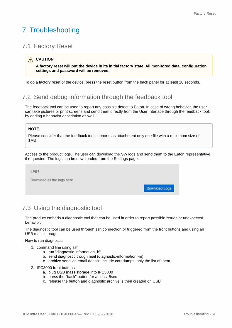
Access to the product logs. The user can download the SW logs and send them to the Eaton representative if requested. The logs can be downloaded from the Settings page.
7.3 Using the diagnostic toolThe product embeds a diagnostic tool that can be used in order to report possible issues or unexpected behavior.
The diagnostic tool can be used through ssh connection or triggered from the front buttons and using an USB mass storage.
How to run diagnostic:
1. command line using ssha. run "diagnostic-information -h"b. send diagnostic trough mail (diagnostic-information -m)c. archive send via email doesn't include coredumps, only the list of them
2. IPC3000 front buttonsa. plug USB mass storage into IPC3000b. press the "back" button for at least 5secc. release the button and diagnostic archive is then created on USB
CAUTION
A factory reset will put the device in its initial factory state. All monitored data, configuration settings and password will be removed.
NOTE
Please consider that the feedback tool supports as attachment only one file with a maximum size of 1MB.

Using the Service port
62 - Troubleshooting IPM Infra User Guide P-164000637 —Rev 1.1 02/28/2018
Consider that creating the archive can take some time and it can be longer if there are coredumps in /var/crash.
Consider that there is no feedback to user that collecting of information is finished. Use some USB stick with LED activity signalization might help and is, therefore, recommended.
7.3.1 Examples of usage:1. Get a list of possible commands.
2. Run the tool and send the details to Eaton product support.
3. Run the tool and send the details to a specific address.
7.4 Using the Service portThe user may connect to the command line interface of the IPC3000 via a point-to-point connection, using the null modem cable delivered in the accessories pack.
For a serial connection, the user shoulduse the serial COM settings indicated below:
• baud rate: 115200• 8 data bits, no parity, 1 stop bit (8-N-1)
