imp-wb-2 hardware user manual
TRANSCRIPT

IMP-WB-2 Hardware User Manual
IMP-WB-2 Hardware User Manual
Version: V.1.2.0
Date: 2017.01
http://www.epcio.com.tw
IMP-WB-2 Hardware User Manual
1
Table of Contents Chapter 1 Overview ..................................................................................................... 2
1.1 Introduction ...................................................................................................... 2
1.2 System Connection Diagram ........................................................................... 2
Chapter 2 Hardware Installation and Operation ..................................................... 3
2.1 Basic Installation Procedure of the System ..................................................... 3
2.2 Board Layout and Mechanical Dimensions ..................................................... 4
2.3 Pin Assignments ............................................................................................... 6
2.3.1 Pin Assignments of Terminal Male Plug (J1) ....................................... 6 2.3.2 Pin Assignments of Servo Connectors (J2~J9) ..................................... 6 2.3.3 Pin Assignments of SCSI II (J10 & J11) Connectors ......................... 17 2.3.4 Pin Assignments of Terminal Blocks (TP1~TP6) ............................... 22 2.3.5 Description of Emergency Stop Switch (SW1) .................................. 23 2.3.6 Assignments of Simulation Switches (SW2~SW9) ............................ 23 2.3.7 Velocity or Torque Command Jumper Blocks (JP1~JP8) ................... 25
2.4 Indicators ........................................................................................................ 26
IMP-WB-2 Hardware User Manual
2
Chapter 1 Overview
1.1 Introduction
IMP-WB-2 is a dedicated adapter developed by the MSL of ITRI for use with the
Panasonic MINAS AC Series servo drives. IMP-WB-2 can connect the Intelligent
Motion control Platform, IMP-2, with servo drives, simplifying the adaption between
peripheral devices during the wiring process. Through dedicated adapter cables,
IMP-WB-2 can also connect with servo drives manufactured by Mitsubishi, Delta,
and Yaskawa.
1.2 System Connection Diagram
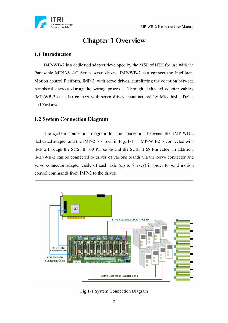
The system connection diagram for the connection between the IMP-WB-2
dedicated adapter and the IMP-2 is shown in Fig. 1-1. IMP-WB-2 is connected with
IMP-2 through the SCSI II 100-Pin cable and the SCSI II 68-Pin cable. In addition,
IMP-WB-2 can be connected to drives of various brands via the servo connector and
servo connector adapter cable of each axis (up to 8 axes) in order to send motion
control commands from IMP-2 to the drives.
J3J1
TP2 TP4 TP6 TP8 TP10 TP12 TP14 TP16
IMC
SCSI II-68Pin Connection Cable
SCSI II-100Pin Connection Cable
Servo Connection Adapter Cable
Servo Connection Adapter Cable
Fig.1-1 System Connection Diagram

IMP-WB-2 Hardware User Manual
3
Chapter 2 Hardware Installation and Operation
2.1 Basic Installation Procedure of the System
A. Before carrying out the basic installation of the system, please carefully
read the user manual.
B. Before removing the IMP-WB-2 adapter from the anti-static bag, please
execute the following steps to avoid electrostatic damage.
Rid your body of static electricity (wear a grounded wrist strap or
lightly touch the metal exterior of a computer with your hand).
Prior to removing the anti-static bag, bring the anti-static bag into
contact with the metal exterior of a computer gently.
When removing the IMP-WB-2 adapter, avoid touching the circuits or
components on the board.
C. After removing IMP-WB-2 from its package, please examine the adapter for
any obvious damage caused by external force (e.g., lost, deformed, or
damaged parts). If such damage is discovered, please stop the installation
process, return the adapter to the anti-static bag, and immediately contact
customer service or the retailer.
D. Be sure to unplug/turn off the power before performing the wiring steps
listed below.
Connect the adapter to the servo drives through the servo connectors
J2~J11.
Refer to the pin assignments of terminal blocks TP1~TP6 for the
wiring of local I/O.
Connect the adapter to IMP-2 through connectors J10 and J11 and the
SCSI II 100-Pin and SCSI II 68-Pin cables.
Connect an external 24 V DC power supply to connector J1 of
IMP-WB-2.
E. IMP-WB-2 must be used with IMP-2 (please make sure that IMP-2 has
been installed completely). Test the adapter through IMP-2 to determine
whether the former can work in a normal manner. The user can also judge
IMP-WB-2 Hardware User Manual
4
by inspecting the indicators (for the configuration of the indicators, please
refer to section 2.4).
2.2 Board Layout and Mechanical Dimensions
Component Name Description
J1 3-Pin Connector To connect with an external 24 V DC power supply. Please refer to section 2.3.1.
J2~J9 Servo Connectors To connect with servo drives. Please refer to section 2.3.2.
J10 SCSI II 100-Pin Connector
To connect with connector J2 of IMP-2. Please refer to section 2.3.3.
J11 SCSI II 68-Pin Connector
To connect with connector J3 of IMP-2. Please refer to section 2.3.3.
TP1~TP6 Wiring Terminal Blocks To provide wiring for local I/O. Please refer to section 2.3.4.
SW1 ESTOP Switch Emergency stop switch. Please refer to section 2.3.5.
SW2~SW9 Simulation Switches Simulate as local input switches. Please refer to section 2.3.6.
JP1~JP8 Velocity or Torque Command Jumper Blocks
To switch between velocity commands and torque commands. Please refer to section 2.3.7.
IMP-WB-2 Hardware User Manual
5
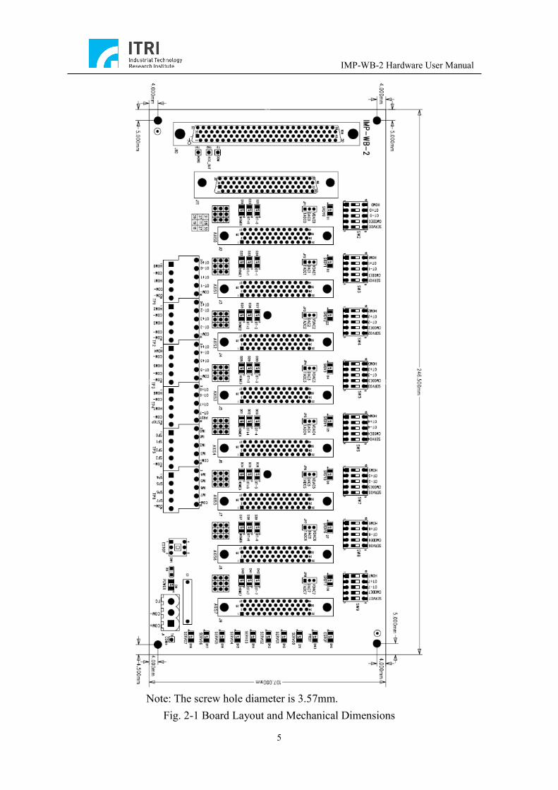
Note: The screw hole diameter is 3.57mm.
Fig. 2-1 Board Layout and Mechanical Dimensions
IMP-WB-2 Hardware User Manual
6
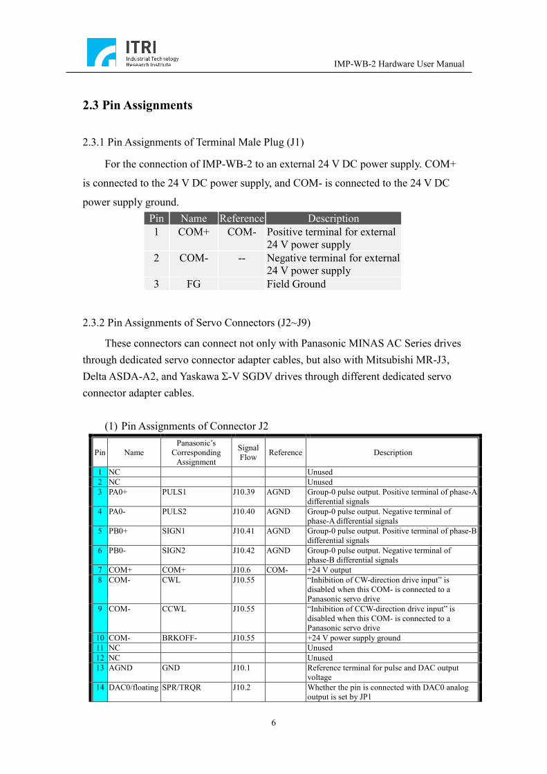
2.3 Pin Assignments
2.3.1 Pin Assignments of Terminal Male Plug (J1)
For the connection of IMP-WB-2 to an external 24 V DC power supply. COM+
is connected to the 24 V DC power supply, and COM- is connected to the 24 V DC
power supply ground. Pin Name Reference Description 1 COM+ COM- Positive terminal for external
24 V power supply 2 COM- -- Negative terminal for external
24 V power supply 3 FG Field Ground
2.3.2 Pin Assignments of Servo Connectors (J2~J9)
These connectors can connect not only with Panasonic MINAS AC Series drives through dedicated servo connector adapter cables, but also with Mitsubishi MR-J3, Delta ASDA-A2, and Yaskawa Σ-V SGDV drives through different dedicated servo connector adapter cables.
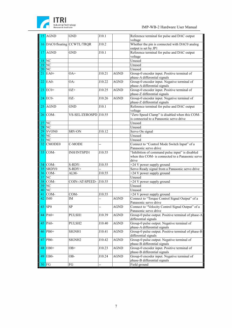
(1) Pin Assignments of Connector J2
Pin Name Panasonic’s
Corresponding Assignment
Signal Flow Reference Description
1 NC Unused 2 NC Unused 3 PA0+ PULS1 J10.39 AGND Group-0 pulse output. Positive terminal of phase-A
differential signals 4 PA0- PULS2 J10.40 AGND Group-0 pulse output. Negative terminal of
phase-A differential signals 5 PB0+ SIGN1 J10.41 AGND Group-0 pulse output. Positive terminal of phase-B
differential signals 6 PB0- SIGN2 J10.42 AGND Group-0 pulse output. Negative terminal of
phase-B differential signals 7 COM+ COM+ J10.6 COM- +24 V output 8 COM- CWL J10.55 “Inhibition of CW-direction drive input” is
disabled when this COM- is connected to a Panasonic servo drive
9 COM- CCWL J10.55 “Inhibition of CCW-direction drive input” is disabled when this COM- is connected to a Panasonic servo drive
10 COM- BRKOFF- J10.55 +24 V power supply ground 11 NC Unused 12 NC Unused 13 AGND GND J10.1 Reference terminal for pulse and DAC output
voltage 14 DAC0/floating SPR/TRQR J10.2 Whether the pin is connected with DAC0 analog
output is set by JP1
IMP-WB-2 Hardware User Manual
7
15 AGND GND J10.1 Reference terminal for pulse and DAC output voltage
16 DAC0/floating CCWTL/TRQR J10.2 Whether the pin is connected with DAC0 analog output is set by JP1
17 AGND GND J10.1 Reference terminal for pulse and DAC output voltage
18 NC Unused 19 NC Unused 20 NC Unused 21 EA0+ OA+ J10.21 AGND Group-0 encoder input. Positive terminal of
phase-A differential signals 22 EA0- OA- J10.22 AGND Group-0 encoder input. Negative terminal of
phase-A differential signals 23 EC0+ OZ+ J10.25 AGND Group-0 encoder input. Positive terminal of
phase-Z differential signals 24 EC0- OZ- J10.26 AGND Group-0 encoder input. Negative terminal of
phase-Z differential signals 25 AGND GND J10.1 Reference terminal for pulse and DAC output
voltage 26 COM- VS-SEL/ZEROSPD J10.55 “Zero Speed Clamp” is disabled when this COM-
is connected to a Panasonic servo drive 27 NC Unused 28 NC Unused 29 SVON0 SRV-ON J10.12 Servo On signal 30 NC Unused 31 NC Unused 32 CMODE0 C-MODE -- Connect to “Control Mode Switch Input” of a
Panasonic servo drive 33 COM- INH/INTSPD1 J10.55 “Inhibition of command pulse input” is disabled
when this COM- is connected to a Panasonic servo drive
34 COM- S-RDY- J10.55 +24 V power supply ground 35 SRDY0 S-RDY+ -- Servo Ready signal from a Panasonic servo drive 36 COM- ALM- J10.55 +24 V power supply ground 37 NC Unused 38 COM- COIN-/AT-SPEED- J10.55 +24 V power supply ground 39 NC Unused 40 NC Unused 41 COM- COM- J10.55 +24 V power supply ground 42 IM0 IM -- AGND Connect to “Torque Control Signal Output” of a
Panasonic servo drive 43 SP0 SP -- AGND Connect to “Velocity Control Signal Output” of a
Panasonic servo drive 44 PA0+ PULSH1 J10.39 AGND Group-0 pulse output. Positive terminal of phase-A
differential signals 45 PA0- PULSH2 J10.40 AGND Group-0 pulse output. Negative terminal of
phase-A differential signals 46 PB0+ SIGNH1 J10.41 AGND Group-0 pulse output. Positive terminal of phase-B
differential signals 47 PB0- SIGNH2 J10.42 AGND Group-0 pulse output. Negative terminal of
phase-B differential signals 48 EB0+ OB+ J10.23 AGND Group-0 encoder input. Positive terminal of
phase-B differential signals 49 EB0- OB- J10.24 AGND Group-0 encoder input. Negative terminal of
phase-B differential signals 50 FG FG -- Field ground

IMP-WB-2 Hardware User Manual
8
(2) Pin Assignments of Connector J3
Pin Name Panasonic’s
Corresponding Assignment
Signal Flow Reference Description
1 NC Unused 2 NC Unused 3 PA1+ PULS1 J10.89 AGND Group-1 pulse output. Positive terminal of phase-A
differential signals 4 PA1- PULS2 J10.90 AGND Group-1 pulse output. Negative terminal of
phase-A differential signals 5 PB1+ SIGN1 J10.91 AGND Group-1 pulse output. Positive terminal of phase-B
differential signals 6 PB1- SIGN2 J10.92 AGND Group-1 pulse output. Negative terminal of
phase-B differential signals 7 COM+ COM+ J10.6 COM- +24 V output 8 COM- CWL J10.55 “Inhibition of CW-direction drive input” is
disabled when this COM- is connected to a Panasonic servo drive
9 COM- CCWL J10.55 “Inhibition of CCW-direction drive input” is disabled when this COM- is connected to a Panasonic servo drive
10 COM- BRKOFF- J10.55 +24 V power supply ground 11 NC Unused 12 NC Unused 13 AGND GND J10.1 Reference terminal for pulse and DAC output
voltage 14 DAC1/floating SPR/TRQR J10.3 Whether the pin is connected with DAC1 analog
output is set by JP2 15 AGND GND J10.1 Reference terminal for pulse and DAC output
voltage 16 DAC1/floating CCWTL/TRQR J10.3 Whether the pin is connected with DAC1 analog
output is set by JP2 17 AGND GND J10.1 Reference terminal for pulse and DAC output
voltage 18 NC Unused 19 NC Unused 20 NC Unused 21 EA1+ OA+ J10.71 AGND Group-1 encoder input. Positive terminal of
phase-A differential signals 22 EA1- OA- J10.72 AGND Group-1 encoder input. Negative terminal of
phase-A differential signals 23 EC1+ OZ+ J10.75 AGND Group-1 encoder input. Positive terminal of
phase-Z differential signals 24 EC1- OZ- J10.76 AGND Group-1 encoder input. Negative terminal of
phase-Z differential signals 25 AGND GND J10.1 Reference terminal for pulse and DAC output
voltage 26 COM- VS-SEL/ZEROSPD J10.55 “Zero Speed Clamp” is disabled when this COM-
is connected to a Panasonic servo drive 27 NC Unused 28 NC Unused 29 SVON1 SRV-ON J10.62 Servo On signal 30 NC Unused 31 NC Unused 32 CMODE1 C-MODE -- Connect to “Control Mode Switch Input” of a
Panasonic servo drive 33 COM- INH/INTSPD1 J10.55 “Inhibition of command pulse input” is disabled
when this COM- is connected to a Panasonic servo drive
34 COM- S-RDY- J10.55 +24 V power supply ground 35 SRDY1 S-RDY+ -- Servo Ready signal from a Panasonic servo drive 36 COM- ALM- J10.55 +24 V power supply ground 37 NC Unused
IMP-WB-2 Hardware User Manual
9
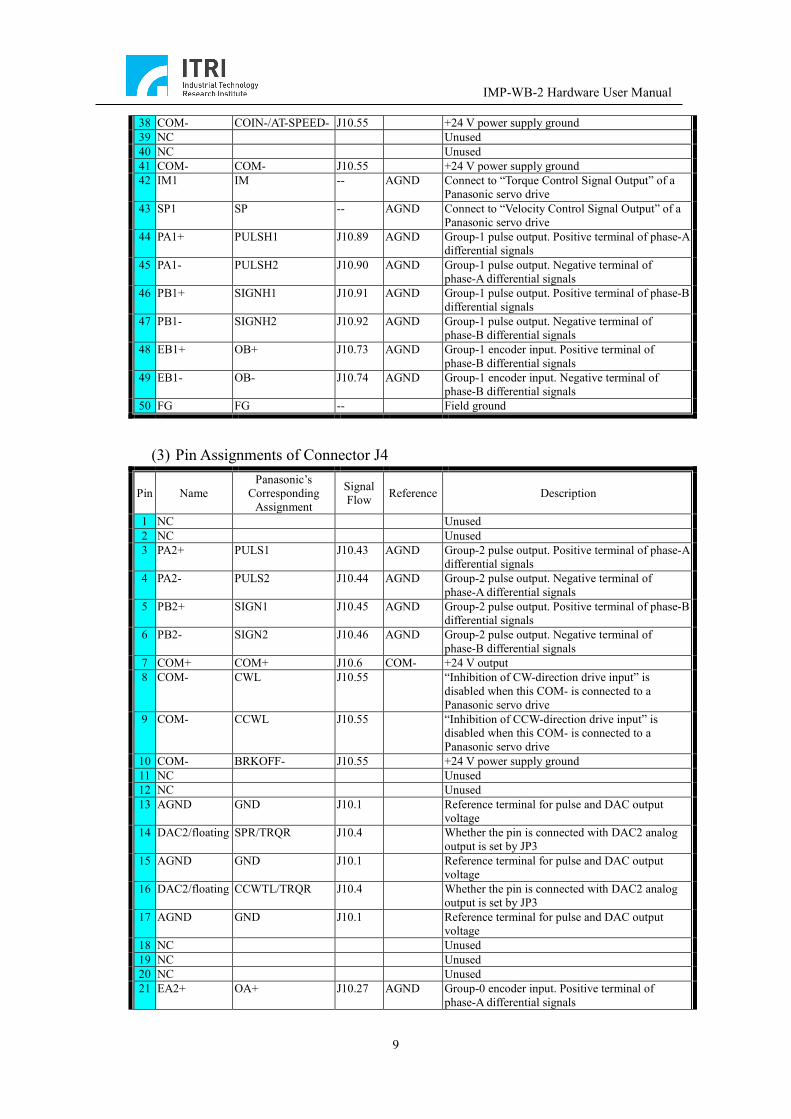
38 COM- COIN-/AT-SPEED- J10.55 +24 V power supply ground 39 NC Unused 40 NC Unused 41 COM- COM- J10.55 +24 V power supply ground 42 IM1 IM -- AGND Connect to “Torque Control Signal Output” of a
Panasonic servo drive 43 SP1 SP -- AGND Connect to “Velocity Control Signal Output” of a
Panasonic servo drive 44 PA1+ PULSH1 J10.89 AGND Group-1 pulse output. Positive terminal of phase-A
differential signals 45 PA1- PULSH2 J10.90 AGND Group-1 pulse output. Negative terminal of
phase-A differential signals 46 PB1+ SIGNH1 J10.91 AGND Group-1 pulse output. Positive terminal of phase-B
differential signals 47 PB1- SIGNH2 J10.92 AGND Group-1 pulse output. Negative terminal of
phase-B differential signals 48 EB1+ OB+ J10.73 AGND Group-1 encoder input. Positive terminal of
phase-B differential signals 49 EB1- OB- J10.74 AGND Group-1 encoder input. Negative terminal of
phase-B differential signals 50 FG FG -- Field ground
(3) Pin Assignments of Connector J4
Pin Name Panasonic’s
Corresponding Assignment
Signal Flow Reference Description
1 NC Unused 2 NC Unused 3 PA2+ PULS1 J10.43 AGND Group-2 pulse output. Positive terminal of phase-A
differential signals 4 PA2- PULS2 J10.44 AGND Group-2 pulse output. Negative terminal of
phase-A differential signals 5 PB2+ SIGN1 J10.45 AGND Group-2 pulse output. Positive terminal of phase-B
differential signals 6 PB2- SIGN2 J10.46 AGND Group-2 pulse output. Negative terminal of
phase-B differential signals 7 COM+ COM+ J10.6 COM- +24 V output 8 COM- CWL J10.55 “Inhibition of CW-direction drive input” is
disabled when this COM- is connected to a Panasonic servo drive
9 COM- CCWL J10.55 “Inhibition of CCW-direction drive input” is disabled when this COM- is connected to a Panasonic servo drive
10 COM- BRKOFF- J10.55 +24 V power supply ground 11 NC Unused 12 NC Unused 13 AGND GND J10.1 Reference terminal for pulse and DAC output
voltage 14 DAC2/floating SPR/TRQR J10.4 Whether the pin is connected with DAC2 analog
output is set by JP3 15 AGND GND J10.1 Reference terminal for pulse and DAC output
voltage 16 DAC2/floating CCWTL/TRQR J10.4 Whether the pin is connected with DAC2 analog
output is set by JP3 17 AGND GND J10.1 Reference terminal for pulse and DAC output
voltage 18 NC Unused 19 NC Unused 20 NC Unused 21 EA2+ OA+ J10.27 AGND Group-0 encoder input. Positive terminal of
phase-A differential signals
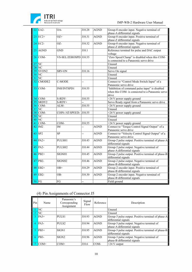
IMP-WB-2 Hardware User Manual
10
22 EA2- OA- J10.28 AGND Group-0 encoder input. Negative terminal of phase-A differential signals
23 EC2+ OZ+ J10.31 AGND Group-0 encoder input. Positive terminal of phase-Z differential signals
24 EC2- OZ- J10.32 AGND Group-0 encoder input. Negative terminal of phase-Z differential signals
25 AGND GND J10.1 Reference terminal for pulse and DAC output voltage
26 COM- VS-SEL/ZEROSPD J10.55 “Zero Speed Clamp” is disabled when this COM- is connected to a Panasonic servo drive
27 NC Unused 28 NC Unused 29 SVON2 SRV-ON J10.16 Servo On signal 30 NC Unused 31 NC Unused 32 CMODE2 C-MODE -- Connect to “Control Mode Switch Input” of a
Panasonic servo drive 33 COM- INH/INTSPD1 J10.55 “Inhibition of command pulse input” is disabled
when this COM- is connected to a Panasonic servo drive
34 COM- S-RDY- J10.55 +24 V power supply ground 35 SRDY2 S-RDY+ -- Servo Ready signal from a Panasonic servo drive 36 COM- ALM- J10.55 +24 V power supply ground 37 NC Unused 38 COM- COIN-/AT-SPEED- J10.55 +24 V power supply ground 39 NC Unused 40 NC Unused 41 COM- COM- J10.55 +24 V power supply ground 42 IM2 IM -- AGND Connect to “Torque Control Signal Output” of a
Panasonic servo drive 43 SP2 SP -- AGND Connect to “Velocity Control Signal Output” of a
Panasonic servo drive 44 PA2+ PULSH1 J10.43 AGND Group-2 pulse output. Positive terminal of phase-A
differential signals 45 PA2- PULSH2 J10.44 AGND Group-2 pulse output. Negative terminal of
phase-A differential signals 46 PB2+ SIGNH1 J10.45 AGND Group-2 pulse output. Positive terminal of phase-B
differential signals 47 PB2- SIGNH2 J10.46 AGND Group-2 pulse output. Negative terminal of
phase-B differential signals 48 EB2+ OB+ J10.29 AGND Group-2 encoder input. Positive terminal of
phase-B differential signals 49 EB2- OB- J10.30 AGND Group-2 encoder input. Negative terminal of
phase-B differential signals 50 FG FG -- Field ground
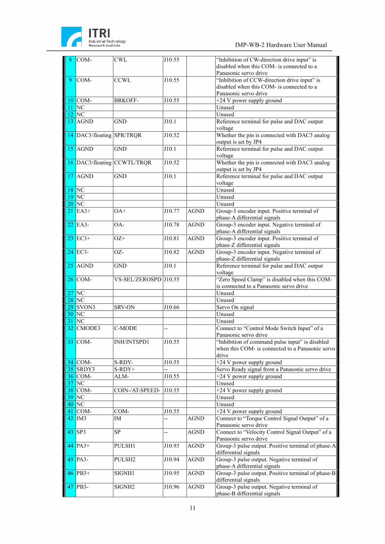
(4) Pin Assignments of Connector J5
Pin Name Panasonic’s
Corresponding Assignment
Signal Flow Reference Description
1 NC Unused 2 NC Unused 3 PA3+ PULS1 J10.93 AGND Group-3 pulse output. Positive terminal of phase-A
differential signals 4 PA3- PULS2 J10.94 AGND Group-3 pulse output. Negative terminal of
phase-A differential signals 5 PB3+ SIGN1 J10.95 AGND Group-3 pulse output. Positive terminal of phase-B
differential signals 6 PB3- SIGN2 J10.96 AGND Group-3 pulse output. Negative terminal of
phase-B differential signals 7 COM+ COM+ J10.6 COM- +24 V output
IMP-WB-2 Hardware User Manual
11
8 COM- CWL J10.55 “Inhibition of CW-direction drive input” is disabled when this COM- is connected to a Panasonic servo drive
9 COM- CCWL J10.55 “Inhibition of CCW-direction drive input” is disabled when this COM- is connected to a Panasonic servo drive
10 COM- BRKOFF- J10.55 +24 V power supply ground 11 NC Unused 12 NC Unused 13 AGND GND J10.1 Reference terminal for pulse and DAC output
voltage 14 DAC3/floating SPR/TRQR J10.52 Whether the pin is connected with DAC3 analog
output is set by JP4 15 AGND GND J10.1 Reference terminal for pulse and DAC output
voltage 16 DAC3/floating CCWTL/TRQR J10.52 Whether the pin is connected with DAC3 analog
output is set by JP4 17 AGND GND J10.1 Reference terminal for pulse and DAC output
voltage 18 NC Unused 19 NC Unused 20 NC Unused 21 EA3+ OA+ J10.77 AGND Group-3 encoder input. Positive terminal of
phase-A differential signals 22 EA3- OA- J10.78 AGND Group-3 encoder input. Negative terminal of
phase-A differential signals 23 EC3+ OZ+ J10.81 AGND Group-3 encoder input. Positive terminal of
phase-Z differential signals 24 EC3- OZ- J10.82 AGND Group-3 encoder input. Negative terminal of
phase-Z differential signals 25 AGND GND J10.1 Reference terminal for pulse and DAC output
voltage 26 COM- VS-SEL/ZEROSPD J10.55 “Zero Speed Clamp” is disabled when this COM-
is connected to a Panasonic servo drive 27 NC Unused 28 NC Unused 29 SVON3 SRV-ON J10.66 Servo On signal 30 NC Unused 31 NC Unused 32 CMODE3 C-MODE -- Connect to “Control Mode Switch Input” of a
Panasonic servo drive 33 COM- INH/INTSPD1 J10.55 “Inhibition of command pulse input” is disabled
when this COM- is connected to a Panasonic servo drive
34 COM- S-RDY- J10.55 +24 V power supply ground 35 SRDY3 S-RDY+ -- Servo Ready signal from a Panasonic servo drive 36 COM- ALM- J10.55 +24 V power supply ground 37 NC Unused 38 COM- COIN-/AT-SPEED- J10.55 +24 V power supply ground 39 NC Unused 40 NC Unused 41 COM- COM- J10.55 +24 V power supply ground 42 IM3 IM -- AGND Connect to “Torque Control Signal Output” of a
Panasonic servo drive 43 SP3 SP -- AGND Connect to “Velocity Control Signal Output” of a
Panasonic servo drive 44 PA3+ PULSH1 J10.93 AGND Group-3 pulse output. Positive terminal of phase-A
differential signals 45 PA3- PULSH2 J10.94 AGND Group-3 pulse output. Negative terminal of
phase-A differential signals 46 PB3+ SIGNH1 J10.95 AGND Group-3 pulse output. Positive terminal of phase-B
differential signals 47 PB3- SIGNH2 J10.96 AGND Group-3 pulse output. Negative terminal of
phase-B differential signals

IMP-WB-2 Hardware User Manual
12
48 EB3+ OB+ J10.79 AGND Group-0 encoder input. Positive terminal of phase-B differential signals
49 EB3- OB- J10.80 AGND Group-0 encoder input. Negative terminal of phase-B differential signals
50 FG FG -- Field ground
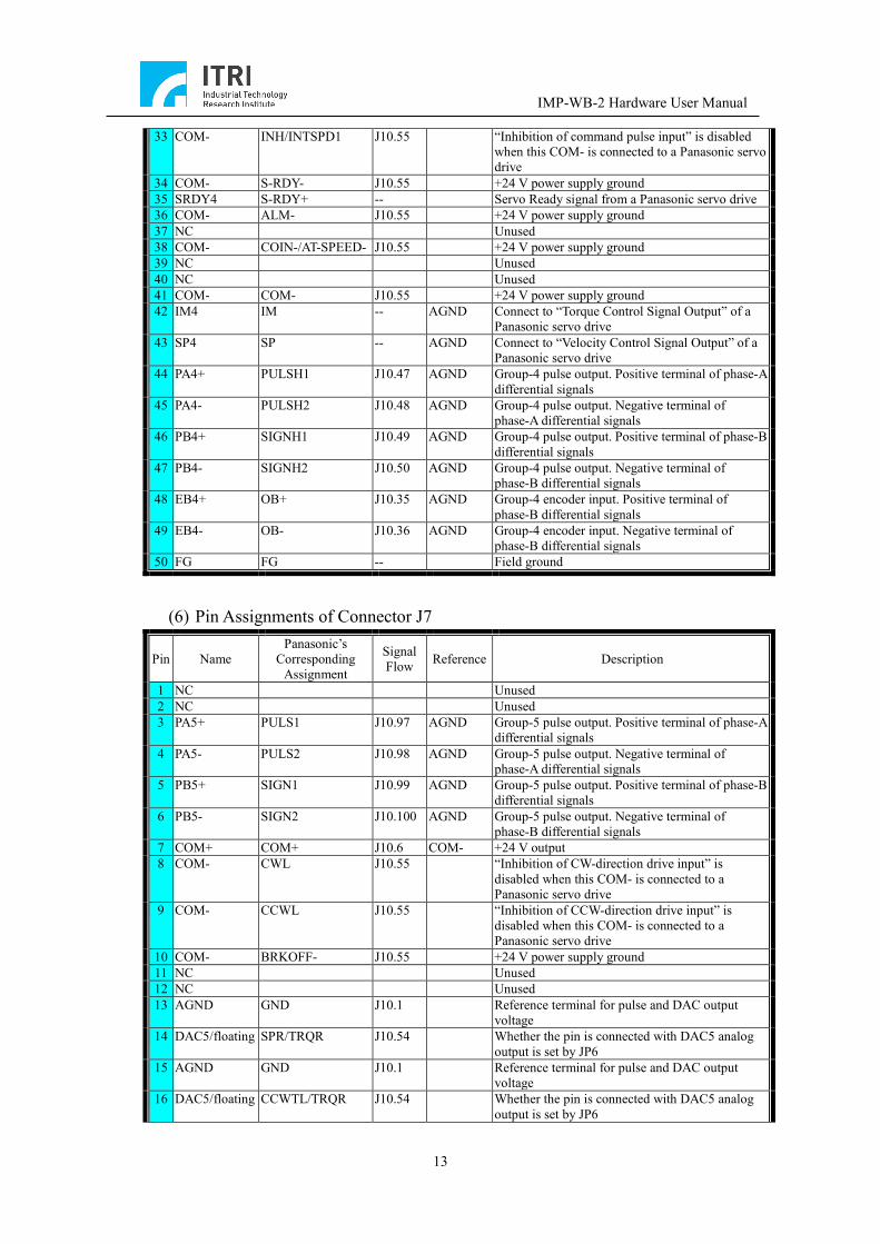
(5) Pin Assignments of Connector J6
Pin Name Panasonic’s
Corresponding Assignment
Signal Flow Reference Description
1 NC Unused 2 NC Unused 3 PA4+ PULS1 J10.47 AGND Group-4 pulse output. Positive terminal of phase-A
differential signals 4 PA4- PULS2 J10.48 AGND Group-4 pulse output. Negative terminal of
phase-A differential signals 5 PB4+ SIGN1 J10.49 AGND Group-4 pulse output. Positive terminal of phase-B
differential signals 6 PB4- SIGN2 J10.50 AGND Group-4 pulse output. Negative terminal of
phase-B differential signals 7 COM+ COM+ J10.6 COM- +24 V output 8 COM- CWL J10.55 “Inhibition of CW-direction drive input” is
disabled when this COM- is connected to a Panasonic servo drive
9 COM- CCWL J10.55 “Inhibition of CCW-direction drive input” is disabled when this COM- is connected to a Panasonic servo drive
10 COM- BRKOFF- J10.55 +24 V power supply ground 11 NC Unused 12 NC Unused 13 AGND GND J10.1 Reference terminal for pulse and DAC output
voltage 14 DAC4/floating SPR/TRQR J10.53 Whether the pin is connected with DAC4 analog
output is set by JP5 15 AGND GND J10.1 Reference terminal for pulse and DAC output
voltage 16 DAC4/floating CCWTL/TRQR J10.53 Whether the pin is connected with DAC4 analog
output is set by JP5 17 AGND GND J10.1 Reference terminal for pulse and DAC output
voltage 18 NC Unused 19 NC Unused 20 NC Unused 21 EA4+ OA+ J10.33 AGND Group-4 encoder input. Positive terminal of
phase-A differential signals 22 EA4- OA- J10.34 AGND Group-4 encoder input. Negative terminal of
phase-A differential signals 23 EC4+ OZ+ J10.37 AGND Group-4 encoder input. Positive terminal of
phase-Z differential signals 24 EC4- OZ- J10.38 AGND Group-4 encoder input. Negative terminal of
phase-Z differential signals 25 AGND GND J10.1 Reference terminal for pulse and DAC output
voltage 26 COM- VS-SEL/ZEROSPD J10.55 “Zero Speed Clamp” is disabled when this COM-
is connected to a Panasonic servo drive 27 NC Unused 28 NC Unused 29 SVON4 SRV-ON J10.20 Servo On signal 30 NC Unused 31 NC Unused 32 CMODE4 C-MODE -- Connect to “Control Mode Switch Input” of a
Panasonic servo drive
IMP-WB-2 Hardware User Manual
13
33 COM- INH/INTSPD1 J10.55 “Inhibition of command pulse input” is disabled when this COM- is connected to a Panasonic servo drive
34 COM- S-RDY- J10.55 +24 V power supply ground 35 SRDY4 S-RDY+ -- Servo Ready signal from a Panasonic servo drive 36 COM- ALM- J10.55 +24 V power supply ground 37 NC Unused 38 COM- COIN-/AT-SPEED- J10.55 +24 V power supply ground 39 NC Unused 40 NC Unused 41 COM- COM- J10.55 +24 V power supply ground 42 IM4 IM -- AGND Connect to “Torque Control Signal Output” of a
Panasonic servo drive 43 SP4 SP -- AGND Connect to “Velocity Control Signal Output” of a
Panasonic servo drive 44 PA4+ PULSH1 J10.47 AGND Group-4 pulse output. Positive terminal of phase-A
differential signals 45 PA4- PULSH2 J10.48 AGND Group-4 pulse output. Negative terminal of
phase-A differential signals 46 PB4+ SIGNH1 J10.49 AGND Group-4 pulse output. Positive terminal of phase-B
differential signals 47 PB4- SIGNH2 J10.50 AGND Group-4 pulse output. Negative terminal of
phase-B differential signals 48 EB4+ OB+ J10.35 AGND Group-4 encoder input. Positive terminal of
phase-B differential signals 49 EB4- OB- J10.36 AGND Group-4 encoder input. Negative terminal of
phase-B differential signals 50 FG FG -- Field ground
(6) Pin Assignments of Connector J7
Pin Name Panasonic’s
Corresponding Assignment
Signal Flow Reference Description
1 NC Unused 2 NC Unused 3 PA5+ PULS1 J10.97 AGND Group-5 pulse output. Positive terminal of phase-A
differential signals 4 PA5- PULS2 J10.98 AGND Group-5 pulse output. Negative terminal of
phase-A differential signals 5 PB5+ SIGN1 J10.99 AGND Group-5 pulse output. Positive terminal of phase-B
differential signals 6 PB5- SIGN2 J10.100 AGND Group-5 pulse output. Negative terminal of
phase-B differential signals 7 COM+ COM+ J10.6 COM- +24 V output 8 COM- CWL J10.55 “Inhibition of CW-direction drive input” is
disabled when this COM- is connected to a Panasonic servo drive
9 COM- CCWL J10.55 “Inhibition of CCW-direction drive input” is disabled when this COM- is connected to a Panasonic servo drive
10 COM- BRKOFF- J10.55 +24 V power supply ground 11 NC Unused 12 NC Unused 13 AGND GND J10.1 Reference terminal for pulse and DAC output
voltage 14 DAC5/floating SPR/TRQR J10.54 Whether the pin is connected with DAC5 analog
output is set by JP6 15 AGND GND J10.1 Reference terminal for pulse and DAC output
voltage 16 DAC5/floating CCWTL/TRQR J10.54 Whether the pin is connected with DAC5 analog
output is set by JP6
IMP-WB-2 Hardware User Manual
14
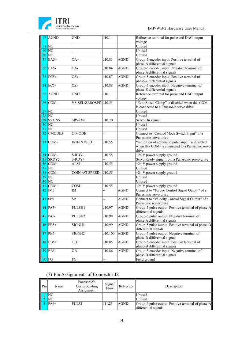
17 AGND GND J10.1 Reference terminal for pulse and DAC output voltage
18 NC Unused 19 NC Unused 20 NC Unused 21 EA5+ OA+ J10.83 AGND Group-5 encoder input. Positive terminal of
phase-A differential signals 22 EA5- OA- J10.84 AGND Group-5 encoder input. Negative terminal of
phase-A differential signals 23 EC5+ OZ+ J10.87 AGND Group-5 encoder input. Positive terminal of
phase-Z differential signals 24 EC5- OZ- J10.88 AGND Group-5 encoder input. Negative terminal of
phase-Z differential signals 25 AGND GND J10.1 Reference terminal for pulse and DAC output
voltage 26 COM- VS-SEL/ZEROSPD J10.55 “Zero Speed Clamp” is disabled when this COM-
is connected to a Panasonic servo drive 27 NC Unused 28 NC Unused 29 SVON5 SRV-ON J10.70 Servo On signal 30 NC Unused 31 NC Unused 32 CMODE5 C-MODE -- Connect to “Control Mode Switch Input” of a
Panasonic servo drive 33 COM- INH/INTSPD1 J10.55 “Inhibition of command pulse input” is disabled
when this COM- is connected to a Panasonic servo drive
34 COM- S-RDY- J10.55 +24 V power supply ground 35 SRDY5 S-RDY+ -- Servo Ready signal from a Panasonic servo drive 36 COM- ALM- J10.55 +24 V power supply ground 37 NC Unused 38 COM- COIN-/AT-SPEED- J10.55 +24 V power supply ground 39 NC Unused 40 NC Unused 41 COM- COM- J10.55 +24 V power supply ground 42 IM5 IM -- AGND Connect to “Torque Control Signal Output” of a
Panasonic servo drive 43 SP5 SP -- AGND Connect to “Velocity Control Signal Output” of a
Panasonic servo drive 44 PA5+ PULSH1 J10.97 AGND Group-5 pulse output. Positive terminal of phase-A
differential signals 45 PA5- PULSH2 J10.98 AGND Group-5 pulse output. Negative terminal of
phase-A differential signals 46 PB5+ SIGNH1 J10.99 AGND Group-5 pulse output. Positive terminal of phase-B
differential signals 47 PB5- SIGNH2 J10.100 AGND Group-5 pulse output. Negative terminal of
phase-B differential signals 48 EB5+ OB+ J10.85 AGND Group-5 encoder input. Positive terminal of
phase-B differential signals 49 EB5- OB- J10.86 AGND Group-5 encoder input. Negative terminal of
phase-B differential signals 50 FG FG -- Field ground
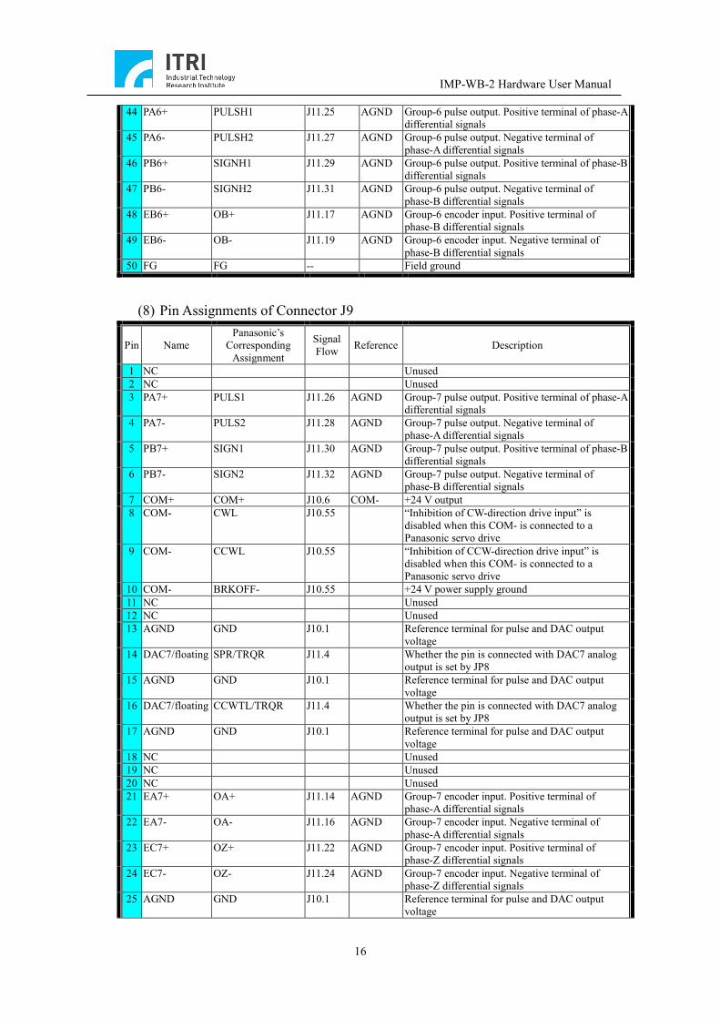
(7) Pin Assignments of Connector J8
Pin Name Panasonic’s
Corresponding Assignment
Signal Flow Reference Description
1 NC Unused 2 NC Unused 3 PA6+ PULS1 J11.25 AGND Group-6 pulse output. Positive terminal of phase-A
differential signals
IMP-WB-2 Hardware User Manual
15
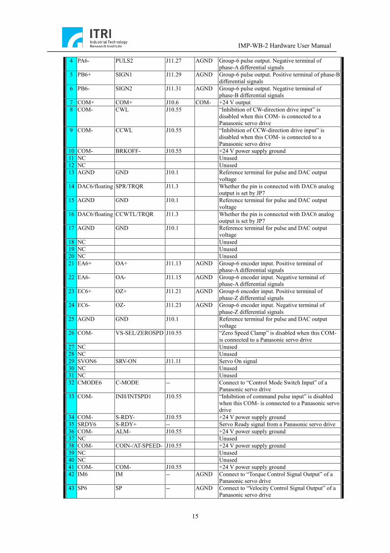
4 PA6- PULS2 J11.27 AGND Group-6 pulse output. Negative terminal of phase-A differential signals
5 PB6+ SIGN1 J11.29 AGND Group-6 pulse output. Positive terminal of phase-B differential signals
6 PB6- SIGN2 J11.31 AGND Group-6 pulse output. Negative terminal of phase-B differential signals
7 COM+ COM+ J10.6 COM- +24 V output 8 COM- CWL J10.55 “Inhibition of CW-direction drive input” is
disabled when this COM- is connected to a Panasonic servo drive
9 COM- CCWL J10.55 “Inhibition of CCW-direction drive input” is disabled when this COM- is connected to a Panasonic servo drive
10 COM- BRKOFF- J10.55 +24 V power supply ground 11 NC Unused 12 NC Unused 13 AGND GND J10.1 Reference terminal for pulse and DAC output
voltage 14 DAC6/floating SPR/TRQR J11.3 Whether the pin is connected with DAC6 analog
output is set by JP7 15 AGND GND J10.1 Reference terminal for pulse and DAC output
voltage 16 DAC6/floating CCWTL/TRQR J11.3 Whether the pin is connected with DAC6 analog
output is set by JP7 17 AGND GND J10.1 Reference terminal for pulse and DAC output
voltage 18 NC Unused 19 NC Unused 20 NC Unused 21 EA6+ OA+ J11.13 AGND Group-6 encoder input. Positive terminal of
phase-A differential signals 22 EA6- OA- J11.15 AGND Group-6 encoder input. Negative terminal of
phase-A differential signals 23 EC6+ OZ+ J11.21 AGND Group-6 encoder input. Positive terminal of
phase-Z differential signals 24 EC6- OZ- J11.23 AGND Group-6 encoder input. Negative terminal of
phase-Z differential signals 25 AGND GND J10.1 Reference terminal for pulse and DAC output
voltage 26 COM- VS-SEL/ZEROSPD J10.55 “Zero Speed Clamp” is disabled when this COM-
is connected to a Panasonic servo drive 27 NC Unused 28 NC Unused 29 SVON6 SRV-ON J11.11 Servo On signal 30 NC Unused 31 NC Unused 32 CMODE6 C-MODE -- Connect to “Control Mode Switch Input” of a
Panasonic servo drive 33 COM- INH/INTSPD1 J10.55 “Inhibition of command pulse input” is disabled
when this COM- is connected to a Panasonic servo drive
34 COM- S-RDY- J10.55 +24 V power supply ground 35 SRDY6 S-RDY+ -- Servo Ready signal from a Panasonic servo drive 36 COM- ALM- J10.55 +24 V power supply ground 37 NC Unused 38 COM- COIN-/AT-SPEED- J10.55 +24 V power supply ground 39 NC Unused 40 NC Unused 41 COM- COM- J10.55 +24 V power supply ground 42 IM6 IM -- AGND Connect to “Torque Control Signal Output” of a
Panasonic servo drive 43 SP6 SP -- AGND Connect to “Velocity Control Signal Output” of a
Panasonic servo drive
IMP-WB-2 Hardware User Manual
16
44 PA6+ PULSH1 J11.25 AGND Group-6 pulse output. Positive terminal of phase-A differential signals
45 PA6- PULSH2 J11.27 AGND Group-6 pulse output. Negative terminal of phase-A differential signals
46 PB6+ SIGNH1 J11.29 AGND Group-6 pulse output. Positive terminal of phase-B differential signals
47 PB6- SIGNH2 J11.31 AGND Group-6 pulse output. Negative terminal of phase-B differential signals
48 EB6+ OB+ J11.17 AGND Group-6 encoder input. Positive terminal of phase-B differential signals
49 EB6- OB- J11.19 AGND Group-6 encoder input. Negative terminal of phase-B differential signals
50 FG FG -- Field ground
(8) Pin Assignments of Connector J9
Pin Name Panasonic’s
Corresponding Assignment
Signal Flow Reference Description
1 NC Unused 2 NC Unused 3 PA7+ PULS1 J11.26 AGND Group-7 pulse output. Positive terminal of phase-A
differential signals 4 PA7- PULS2 J11.28 AGND Group-7 pulse output. Negative terminal of
phase-A differential signals 5 PB7+ SIGN1 J11.30 AGND Group-7 pulse output. Positive terminal of phase-B
differential signals 6 PB7- SIGN2 J11.32 AGND Group-7 pulse output. Negative terminal of
phase-B differential signals 7 COM+ COM+ J10.6 COM- +24 V output 8 COM- CWL J10.55 “Inhibition of CW-direction drive input” is
disabled when this COM- is connected to a Panasonic servo drive
9 COM- CCWL J10.55 “Inhibition of CCW-direction drive input” is disabled when this COM- is connected to a Panasonic servo drive
10 COM- BRKOFF- J10.55 +24 V power supply ground 11 NC Unused 12 NC Unused 13 AGND GND J10.1 Reference terminal for pulse and DAC output
voltage 14 DAC7/floating SPR/TRQR J11.4 Whether the pin is connected with DAC7 analog
output is set by JP8 15 AGND GND J10.1 Reference terminal for pulse and DAC output
voltage 16 DAC7/floating CCWTL/TRQR J11.4 Whether the pin is connected with DAC7 analog
output is set by JP8 17 AGND GND J10.1 Reference terminal for pulse and DAC output
voltage 18 NC Unused 19 NC Unused 20 NC Unused 21 EA7+ OA+ J11.14 AGND Group-7 encoder input. Positive terminal of
phase-A differential signals 22 EA7- OA- J11.16 AGND Group-7 encoder input. Negative terminal of
phase-A differential signals 23 EC7+ OZ+ J11.22 AGND Group-7 encoder input. Positive terminal of
phase-Z differential signals 24 EC7- OZ- J11.24 AGND Group-7 encoder input. Negative terminal of
phase-Z differential signals 25 AGND GND J10.1 Reference terminal for pulse and DAC output
voltage
IMP-WB-2 Hardware User Manual
17
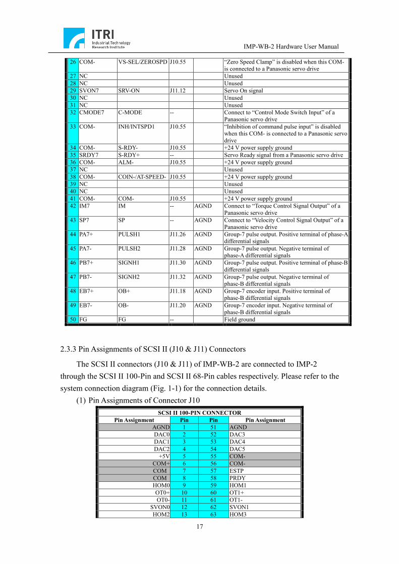
26 COM- VS-SEL/ZEROSPD J10.55 “Zero Speed Clamp” is disabled when this COM- is connected to a Panasonic servo drive
27 NC Unused 28 NC Unused 29 SVON7 SRV-ON J11.12 Servo On signal 30 NC Unused 31 NC Unused 32 CMODE7 C-MODE -- Connect to “Control Mode Switch Input” of a
Panasonic servo drive 33 COM- INH/INTSPD1 J10.55 “Inhibition of command pulse input” is disabled
when this COM- is connected to a Panasonic servo drive
34 COM- S-RDY- J10.55 +24 V power supply ground 35 SRDY7 S-RDY+ -- Servo Ready signal from a Panasonic servo drive 36 COM- ALM- J10.55 +24 V power supply ground 37 NC Unused 38 COM- COIN-/AT-SPEED- J10.55 +24 V power supply ground 39 NC Unused 40 NC Unused 41 COM- COM- J10.55 +24 V power supply ground 42 IM7 IM -- AGND Connect to “Torque Control Signal Output” of a
Panasonic servo drive 43 SP7 SP -- AGND Connect to “Velocity Control Signal Output” of a
Panasonic servo drive 44 PA7+ PULSH1 J11.26 AGND Group-7 pulse output. Positive terminal of phase-A
differential signals 45 PA7- PULSH2 J11.28 AGND Group-7 pulse output. Negative terminal of
phase-A differential signals 46 PB7+ SIGNH1 J11.30 AGND Group-7 pulse output. Positive terminal of phase-B
differential signals 47 PB7- SIGNH2 J11.32 AGND Group-7 pulse output. Negative terminal of
phase-B differential signals 48 EB7+ OB+ J11.18 AGND Group-7 encoder input. Positive terminal of
phase-B differential signals 49 EB7- OB- J11.20 AGND Group-7 encoder input. Negative terminal of
phase-B differential signals 50 FG FG -- Field ground
2.3.3 Pin Assignments of SCSI II (J10 & J11) Connectors
The SCSI II connectors (J10 & J11) of IMP-WB-2 are connected to IMP-2 through the SCSI II 100-Pin and SCSI II 68-Pin cables respectively. Please refer to the system connection diagram (Fig. 1-1) for the connection details.
(1) Pin Assignments of Connector J10 SCSI II 100-PIN CONNECTOR
Pin Assignment Pin Pin Pin Assignment AGND 1 51 AGND DAC0 2 52 DAC3 DAC1 3 53 DAC4 DAC2 4 54 DAC5
+5V 5 55 COM- COM+ 6 56 COM- COM 7 57 ESTP COM 8 58 PRDY HOM0 9 59 HOM1 OT0+ 10 60 OT1+ OT0- 11 61 OT1-
SVON0 12 62 SVON1 HOM2 13 63 HOM3
IMP-WB-2 Hardware User Manual
18
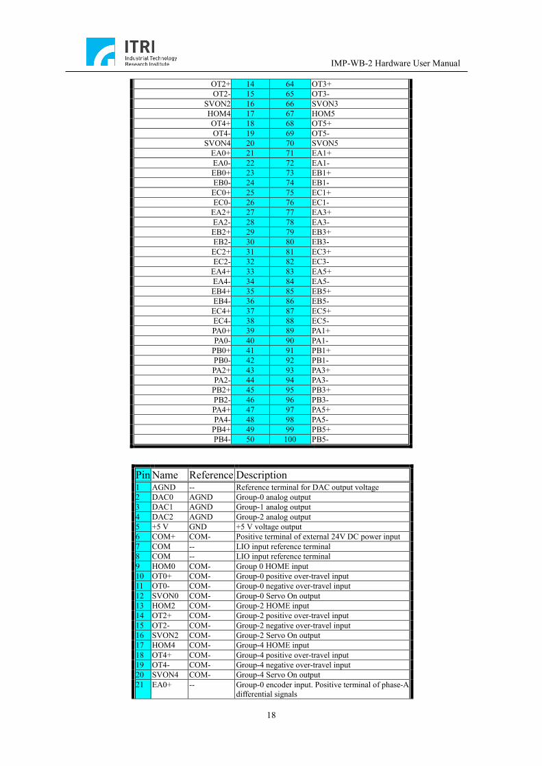
OT2+ 14 64 OT3+ OT2- 15 65 OT3-
SVON2 16 66 SVON3 HOM4 17 67 HOM5 OT4+ 18 68 OT5+ OT4- 19 69 OT5-
SVON4 20 70 SVON5 EA0+ 21 71 EA1+ EA0- 22 72 EA1- EB0+ 23 73 EB1+ EB0- 24 74 EB1- EC0+ 25 75 EC1+ EC0- 26 76 EC1-
EA2+ 27 77 EA3+ EA2- 28 78 EA3- EB2+ 29 79 EB3+ EB2- 30 80 EB3- EC2+ 31 81 EC3+ EC2- 32 82 EC3-
EA4+ 33 83 EA5+ EA4- 34 84 EA5- EB4+ 35 85 EB5+ EB4- 36 86 EB5- EC4+ 37 87 EC5+ EC4- 38 88 EC5- PA0+ 39 89 PA1+ PA0- 40 90 PA1-
PB0+ 41 91 PB1+ PB0- 42 92 PB1- PA2+ 43 93 PA3+ PA2- 44 94 PA3-
PB2+ 45 95 PB3+ PB2- 46 96 PB3- PA4+ 47 97 PA5+ PA4- 48 98 PA5-
PB4+ 49 99 PB5+ PB4- 50 100 PB5-
Pin Name Reference Description 1 AGND -- Reference terminal for DAC output voltage 2 DAC0 AGND Group-0 analog output 3 DAC1 AGND Group-1 analog output 4 DAC2 AGND Group-2 analog output 5 +5 V GND +5 V voltage output 6 COM+ COM- Positive terminal of external 24V DC power input 7 COM -- LIO input reference terminal 8 COM -- LIO input reference terminal 9 HOM0 COM- Group 0 HOME input 10 OT0+ COM- Group-0 positive over-travel input 11 OT0- COM- Group-0 negative over-travel input 12 SVON0 COM- Group-0 Servo On output 13 HOM2 COM- Group-2 HOME input 14 OT2+ COM- Group-2 positive over-travel input 15 OT2- COM- Group-2 negative over-travel input 16 SVON2 COM- Group-2 Servo On output 17 HOM4 COM- Group-4 HOME input 18 OT4+ COM- Group-4 positive over-travel input 19 OT4- COM- Group-4 negative over-travel input 20 SVON4 COM- Group-4 Servo On output 21 EA0+ -- Group-0 encoder input. Positive terminal of phase-A
differential signals
IMP-WB-2 Hardware User Manual
19
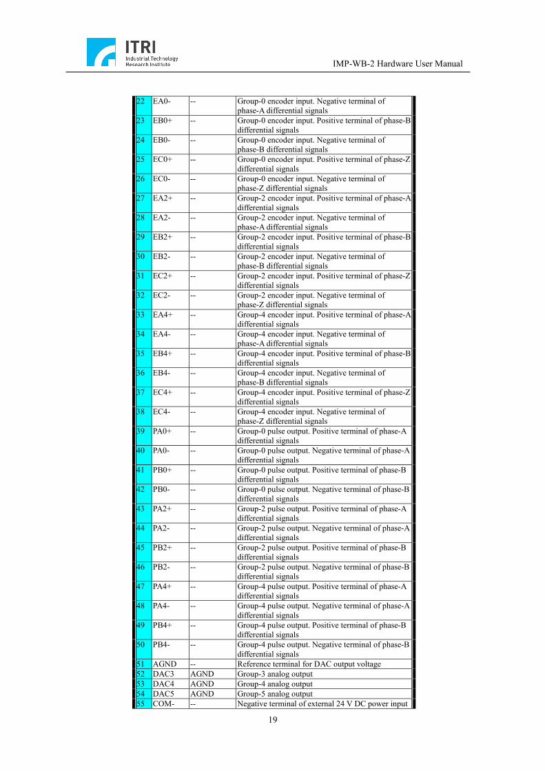
22 EA0- -- Group-0 encoder input. Negative terminal of
phase-A differential signals 23 EB0+ -- Group-0 encoder input. Positive terminal of phase-B
differential signals 24 EB0- -- Group-0 encoder input. Negative terminal of
phase-B differential signals 25 EC0+ -- Group-0 encoder input. Positive terminal of phase-Z
differential signals 26 EC0- -- Group-0 encoder input. Negative terminal of
phase-Z differential signals 27 EA2+ -- Group-2 encoder input. Positive terminal of phase-A
differential signals 28 EA2- -- Group-2 encoder input. Negative terminal of
phase-A differential signals 29 EB2+ -- Group-2 encoder input. Positive terminal of phase-B
differential signals 30 EB2- -- Group-2 encoder input. Negative terminal of
phase-B differential signals 31 EC2+ -- Group-2 encoder input. Positive terminal of phase-Z
differential signals 32 EC2- -- Group-2 encoder input. Negative terminal of
phase-Z differential signals 33 EA4+ -- Group-4 encoder input. Positive terminal of phase-A
differential signals 34 EA4- -- Group-4 encoder input. Negative terminal of
phase-A differential signals 35 EB4+ -- Group-4 encoder input. Positive terminal of phase-B
differential signals 36 EB4- -- Group-4 encoder input. Negative terminal of
phase-B differential signals 37 EC4+ -- Group-4 encoder input. Positive terminal of phase-Z
differential signals 38 EC4- -- Group-4 encoder input. Negative terminal of
phase-Z differential signals 39 PA0+ -- Group-0 pulse output. Positive terminal of phase-A
differential signals 40 PA0- -- Group-0 pulse output. Negative terminal of phase-A
differential signals 41 PB0+ -- Group-0 pulse output. Positive terminal of phase-B
differential signals 42 PB0- -- Group-0 pulse output. Negative terminal of phase-B
differential signals 43 PA2+ -- Group-2 pulse output. Positive terminal of phase-A
differential signals 44 PA2- -- Group-2 pulse output. Negative terminal of phase-A
differential signals 45 PB2+ -- Group-2 pulse output. Positive terminal of phase-B
differential signals 46 PB2- -- Group-2 pulse output. Negative terminal of phase-B
differential signals 47 PA4+ -- Group-4 pulse output. Positive terminal of phase-A
differential signals 48 PA4- -- Group-4 pulse output. Negative terminal of phase-A
differential signals 49 PB4+ -- Group-4 pulse output. Positive terminal of phase-B
differential signals 50 PB4- -- Group-4 pulse output. Negative terminal of phase-B
differential signals 51 AGND -- Reference terminal for DAC output voltage 52 DAC3 AGND Group-3 analog output 53 DAC4 AGND Group-4 analog output 54 DAC5 AGND Group-5 analog output 55 COM- -- Negative terminal of external 24 V DC power input
IMP-WB-2 Hardware User Manual
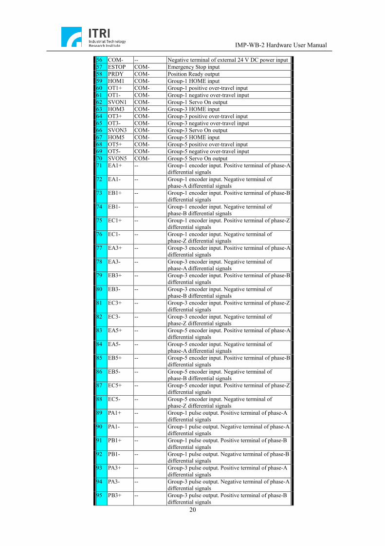
20
56 COM- -- Negative terminal of external 24 V DC power input 57 ESTOP COM- Emergency Stop input 58 PRDY COM- Position Ready output 59 HOM1 COM- Group-1 HOME input 60 OT1+ COM- Group-1 positive over-travel input 61 OT1- COM- Group-1 negative over-travel input 62 SVON1 COM- Group-1 Servo On output 63 HOM3 COM- Group-3 HOME input 64 OT3+ COM- Group-3 positive over-travel input 65 OT3- COM- Group-3 negative over-travel input 66 SVON3 COM- Group-3 Servo On output 67 HOM5 COM- Group-5 HOME input 68 OT5+ COM- Group-5 positive over-travel input 69 OT5- COM- Group-5 negative over-travel input 70 SVON5 COM- Group-5 Servo On output 71 EA1+ -- Group-1 encoder input. Positive terminal of phase-A
differential signals 72 EA1- -- Group-1 encoder input. Negative terminal of
phase-A differential signals 73 EB1+ -- Group-1 encoder input. Positive terminal of phase-B
differential signals 74 EB1- -- Group-1 encoder input. Negative terminal of
phase-B differential signals 75 EC1+ -- Group-1 encoder input. Positive terminal of phase-Z
differential signals 76 EC1- -- Group-1 encoder input. Negative terminal of
phase-Z differential signals 77 EA3+ -- Group-3 encoder input. Positive terminal of phase-A
differential signals 78 EA3- -- Group-3 encoder input. Negative terminal of
phase-A differential signals 79 EB3+ -- Group-3 encoder input. Positive terminal of phase-B
differential signals 80 EB3- -- Group-3 encoder input. Negative terminal of
phase-B differential signals 81 EC3+ -- Group-3 encoder input. Positive terminal of phase-Z
differential signals 82 EC3- -- Group-3 encoder input. Negative terminal of
phase-Z differential signals 83 EA5+ -- Group-5 encoder input. Positive terminal of phase-A
differential signals 84 EA5- -- Group-5 encoder input. Negative terminal of
phase-A differential signals 85 EB5+ -- Group-5 encoder input. Positive terminal of phase-B
differential signals 86 EB5- -- Group-5 encoder input. Negative terminal of
phase-B differential signals 87 EC5+ -- Group-5 encoder input. Positive terminal of phase-Z
differential signals 88 EC5- -- Group-5 encoder input. Negative terminal of
phase-Z differential signals 89 PA1+ -- Group-1 pulse output. Positive terminal of phase-A
differential signals 90 PA1- -- Group-1 pulse output. Negative terminal of phase-A
differential signals 91 PB1+ -- Group-1 pulse output. Positive terminal of phase-B
differential signals 92 PB1- -- Group-1 pulse output. Negative terminal of phase-B
differential signals 93 PA3+ -- Group-3 pulse output. Positive terminal of phase-A
differential signals 94 PA3- -- Group-3 pulse output. Negative terminal of phase-A
differential signals 95 PB3+ -- Group-3 pulse output. Positive terminal of phase-B
differential signals

IMP-WB-2 Hardware User Manual
21
96 PB3- -- Group-3 pulse output. Negative terminal of phase-B differential signals
97 PA5+ -- Group-5 pulse output. Positive terminal of phase-A differential signals
98 PA5- -- Group-5 pulse output. Negative terminal of phase-A differential signals
99 PB5+ -- Group-5 pulse output. Positive terminal of phase-B differential signals
100 PB5- -- Group-5 pulse output. Negative terminal of phase-B differential signals
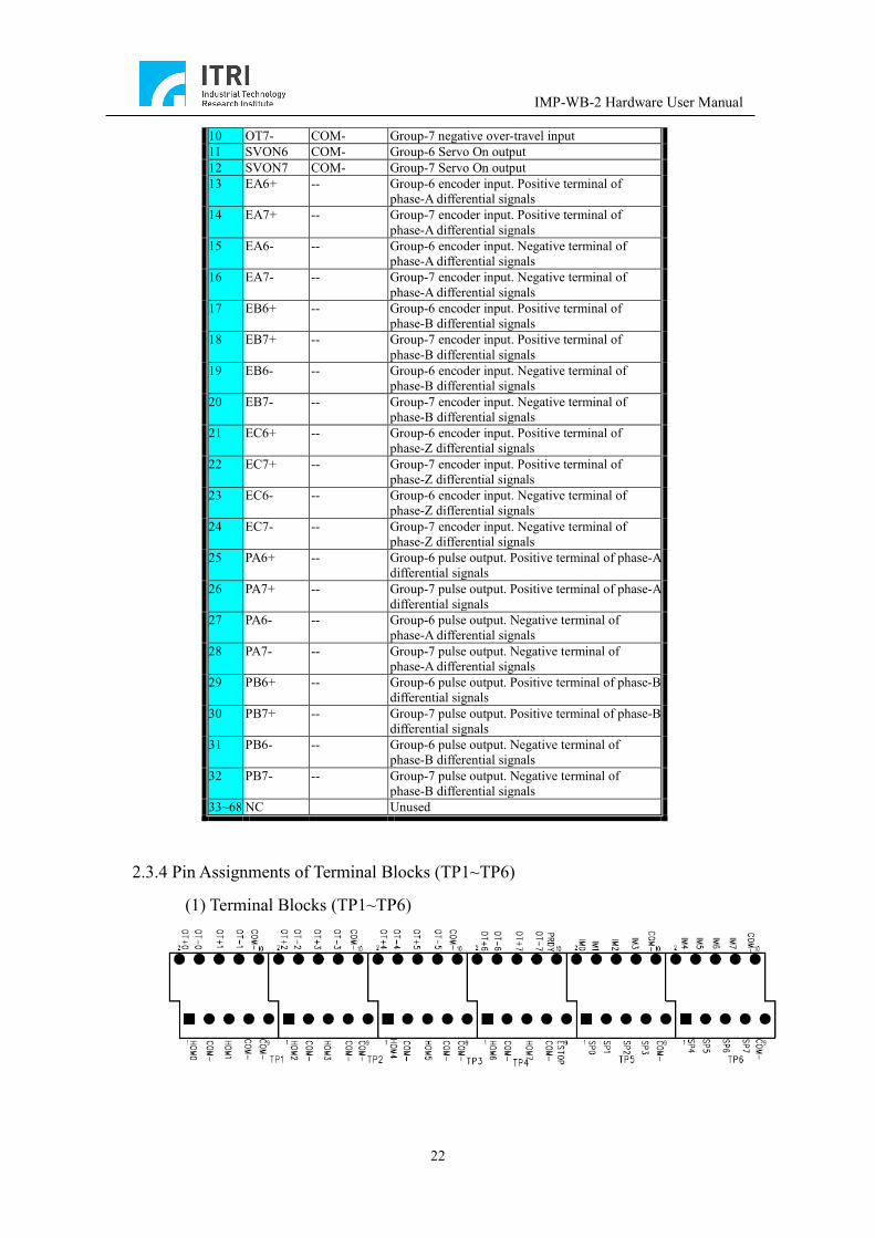
(2) Pin Assignments of Connector J11
SCSI II 68-PIN CONNECTOR Pin Assignment Pin Pin Pin Assignment
AGND 1 35 NC AGND 2 36 NC DAC6 3 37 NC DAC7 4 38 NC HOM6 5 39 GND HOM7 6 40 GND OT6+ 7 41 NC OT7+ 8 42 NC OT6- 9 43 NC OT7- 10 44 NC
SVON6 11 45 NC SVON7 12 46 NC
EA6+ 13 47 NC EA7+ 14 48 NC EA6- 15 49 NC EA7- 16 50 NC EB6+ 17 51 NC EB7+ 18 52 NC EB6- 19 53 NC EB7- 20 54 NC EC6+ 21 55 NC EC7+ 22 56 NC EC6- 23 57 NC EC7- 24 58 NC PA6+ 25 59 NC PA7+ 26 60 NC PA6- 27 61 NC PA7- 28 62 NC
PB6+ 29 63 NC PB7+ 30 64 NC PB6- 31 65 NC PB7- 32 66 NC
NC 33 67 NC NC 34 68 NC
Pin Name Reference Description 1 AGND -- Reference terminal for DAC output voltage 2 AGND -- Reference terminal for DAC output voltage 3 DAC6 AGND Group-6 analog output 4 DAC7 AGND Group-7 analog output 5 HOM6 COM- Group-6 HOME input 6 HOM7 COM- Group-7 HOME input 7 OT6+ COM- Group-6 positive over-travel input 8 OT7+ COM- Group-7 positive over-travel input 9 OT6- COM- Group-6 negative over-travel input
IMP-WB-2 Hardware User Manual
22
10 OT7- COM- Group-7 negative over-travel input 11 SVON6 COM- Group-6 Servo On output 12 SVON7 COM- Group-7 Servo On output 13 EA6+ -- Group-6 encoder input. Positive terminal of
phase-A differential signals 14 EA7+ -- Group-7 encoder input. Positive terminal of
phase-A differential signals 15 EA6- -- Group-6 encoder input. Negative terminal of
phase-A differential signals 16 EA7- -- Group-7 encoder input. Negative terminal of
phase-A differential signals 17 EB6+ -- Group-6 encoder input. Positive terminal of
phase-B differential signals 18 EB7+ -- Group-7 encoder input. Positive terminal of
phase-B differential signals 19 EB6- -- Group-6 encoder input. Negative terminal of
phase-B differential signals 20 EB7- -- Group-7 encoder input. Negative terminal of
phase-B differential signals 21 EC6+ -- Group-6 encoder input. Positive terminal of
phase-Z differential signals 22 EC7+ -- Group-7 encoder input. Positive terminal of
phase-Z differential signals 23 EC6- -- Group-6 encoder input. Negative terminal of
phase-Z differential signals 24 EC7- -- Group-7 encoder input. Negative terminal of
phase-Z differential signals 25 PA6+ -- Group-6 pulse output. Positive terminal of phase-A
differential signals 26 PA7+ -- Group-7 pulse output. Positive terminal of phase-A
differential signals 27 PA6- -- Group-6 pulse output. Negative terminal of
phase-A differential signals 28 PA7- -- Group-7 pulse output. Negative terminal of
phase-A differential signals 29 PB6+ -- Group-6 pulse output. Positive terminal of phase-B
differential signals 30 PB7+ -- Group-7 pulse output. Positive terminal of phase-B
differential signals 31 PB6- -- Group-6 pulse output. Negative terminal of
phase-B differential signals 32 PB7- -- Group-7 pulse output. Negative terminal of
phase-B differential signals 33~68 NC Unused
2.3.4 Pin Assignments of Terminal Blocks (TP1~TP6)
(1) Terminal Blocks (TP1~TP6)
IMP-WB-2 Hardware User Manual
23
Assignment Description COM- 24 V ground OTn+ Group-n positive over-travel limit switch
input HOMn Group-n HOME switch input OTn- Group-n negative over-travel limit switch
input IMn Group-n analog control signal output. Refer
to Servo Drive User Manual. SPn PRDY Position Ready output ESTOP Emergency Stop input
2.3.5 Description of Emergency Stop Switch (SW1)
Used in parallel with the terminal blocks. If the ESTOP is connected with an
external emergency stop button, the ESTOP (SW1) should be set to OFF. If there is no
external emergency stop button, this switch can function as an emergency stop button:
when the switch is pressed down and therefore set to ON, it is the normal operation
state, and when the switch is set to OFF, it is the emergency stop state.
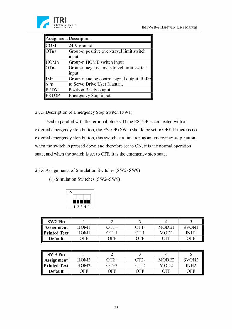
2.3.6 Assignments of Simulation Switches (SW2~SW9)
(1) Simulation Switches (SW2~SW9)
ON ▉ ▉ ▉ ▉ ▉ 1 2 3 4 5
SW2 Pin 1 2 3 4 5 Assignment HOM1 OT1+ OT1- MODE1 SVON1 Printed Text HOM1 OT+1 OT-1 MOD1 INH1
Default OFF OFF OFF OFF OFF
SW3 Pin 1 2 3 4 5 Assignment HOM2 OT2+ OT2- MODE2 SVON2 Printed Text HOM2 OT+2 OT-2 MOD2 INH2
Default OFF OFF OFF OFF OFF

IMP-WB-2 Hardware User Manual
24
SW4 Pin 1 2 3 4 5 Assignment HOM3 OT3+ OT3- MODE3 SVON3 Printed Text HOM3 OT+3 OT-3 MOD3 INH3
Default OFF OFF OFF OFF OFF
SW5 Pin 1 2 3 4 5 Assignment HOM4 OT4+ OT4- MODE4 SVON4 Printed Text HOM4 OT+4 OT-4 MOD4 INH4
Default OFF OFF OFF OFF OFF
SW6 Pin 1 2 3 4 5 Assignment HOM5 OT5+ OT5- MODE5 SVON5 Printed Text HOM5 OT+5 OT-5 MOD5 INH5
Default OFF OFF OFF OFF OFF
SW7 Pin 1 2 3 4 5 Assignment HOM6 OT6+ OT6- MODE6 SVON6 Printed Text HOM6 OT+6 OT-6 MOD6 INH6
Default OFF OFF OFF OFF OFF
SW8 Pin 1 2 3 4 5 Assignment HOM7 OT7+ OT7- MODE7 SVON7 Printed Text HOM7 OT+7 OT-7 MOD7 INH7
Default OFF OFF OFF OFF OFF
SW9 Pin 1 2 3 4 5 Assignment HOM8 OT8+ OT8- MODE8 SVON8 Printed Text HOM8 OT+8 OT-8 MOD8 INH8
Default OFF OFF OFF OFF OFF
(2) Description and Settings HOMn (n = 0~7): Used in parallel with the terminal blocks. If the Home
contact of a terminal block is connected with an external Home sensor, the corresponding HOMn should be set to the OFF position. If there is no external Home sensor for a certain axis, the corresponding dip switch can function as a Home sensor. In that case, a HOMn set to ON indicates that connection has been established with the Home sensor signal of the corresponding axis.
OTn+ (n = 0~7): Used in parallel with the terminal blocks. If the OT+ contact of a terminal block is connected with an external limit switch, the
IMP-WB-2 Hardware User Manual
25
corresponding OTn+ should be set to the OFF position. If there is no external limit switch for a certain axis, the corresponding dip switch can function as a limit switch. In that case, an OTn+ set to ON indicates that connection has been established with the positive over-travel limit switch signal of the corresponding axis.
OTn- (n = 0~7): Used in parallel with the terminal blocks. When the OT- contact of a terminal blocks is connected with an external limit switch, the corresponding OTn- should be set to the OFF position. If there is no external limit switch for a certain axis, the corresponding dip switch can function as a limit switch. In that case, an OTn- set to ON indicates that connection has been established with the negative over-travel limit switch signal of the corresponding axis.
MODn (n = 0~7): Used for C-MODE (control mode) selection. Please refer to Servo Drive User Manual for the required settings for personal use. Set to OFF when left unused.
INHn (n = 0~7): Used in parallel with servo drive connectors. If a Servo On signal is to be output from the motion control platform, the corresponding INHn should be set to the OFF position when connected to the drive. An INHn can also be set to the ON position to function as Servo On.
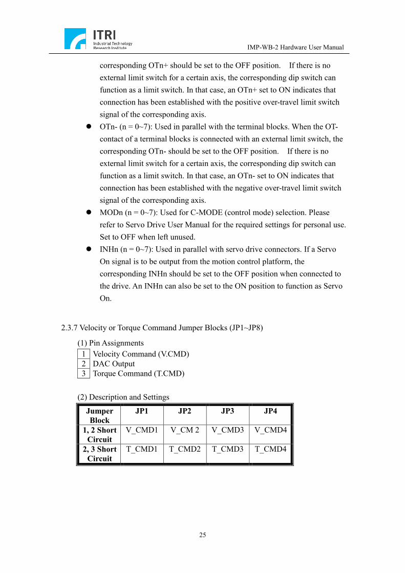
2.3.7 Velocity or Torque Command Jumper Blocks (JP1~JP8)
(1) Pin Assignments 1 Velocity Command (V.CMD) 2 DAC Output 3 Torque Command (T.CMD)
(2) Description and Settings
Jumper Block
JP1 JP2 JP3 JP4
1, 2 Short Circuit
V_CMD1 V_CM 2 V_CMD3 V_CMD4
2, 3 Short Circuit
T_CMD1 T_CMD2 T_CMD3 T_CMD4
IMP-WB-2 Hardware User Manual
26
Jumper Block
JP5 JP6 JP7 JP8
1, 2 Short Circuit
V_CMD5 V_CMD6 V_CMD7 V_CMD8
2, 3 Short Circuit
T_CMD5 T_CMD6 T_CMD7 T_CMD8
* The jumper settings listed above are ineffective if the pulse mode is set for the motor drives.
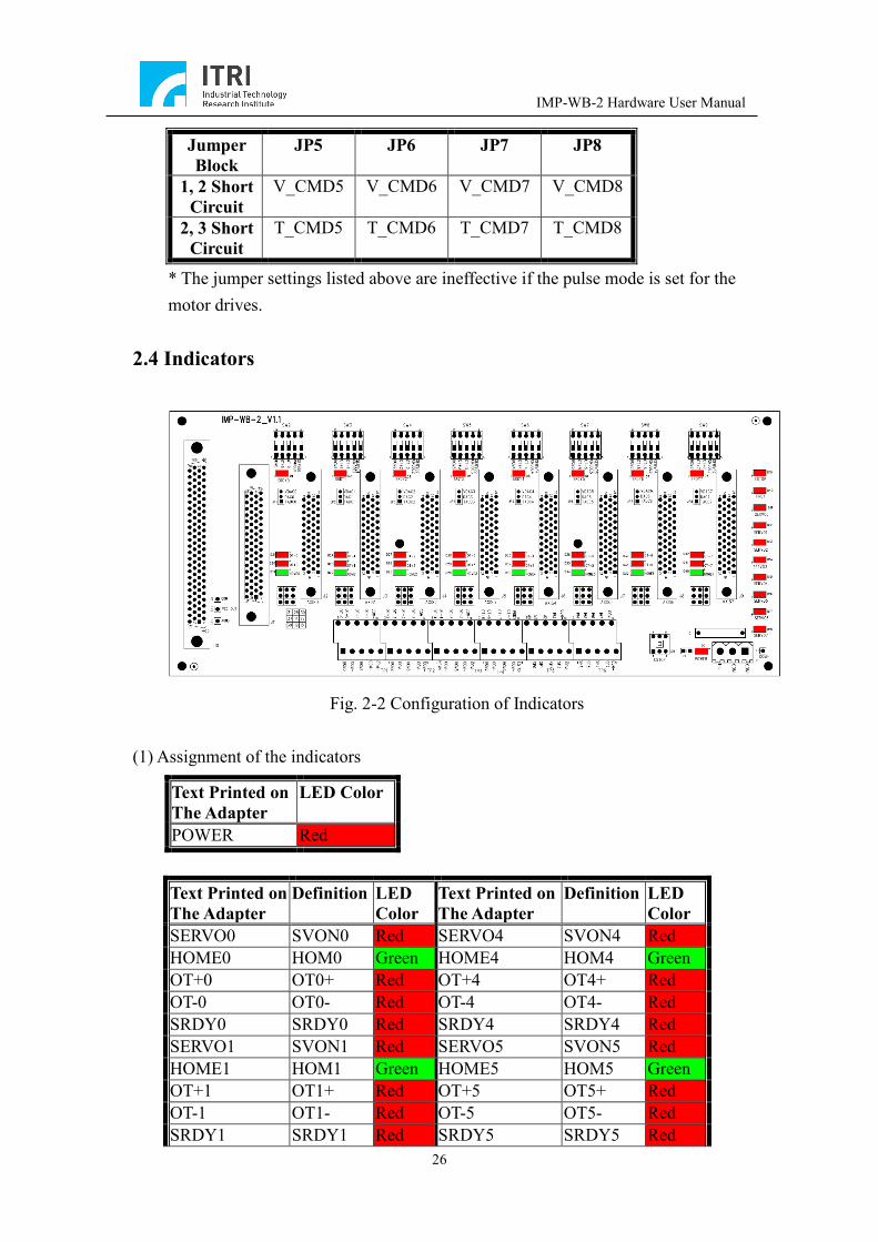
2.4 Indicators
Fig. 2-2 Configuration of Indicators
(1) Assignment of the indicators
Text Printed on The Adapter
Definition LED Color
Text Printed on The Adapter
Definition LED Color
SERVO0 SVON0 Red SERVO4 SVON4 Red HOME0 HOM0 Green HOME4 HOM4 Green OT+0 OT0+ Red OT+4 OT4+ Red OT-0 OT0- Red OT-4 OT4- Red SRDY0 SRDY0 Red SRDY4 SRDY4 Red SERVO1 SVON1 Red SERVO5 SVON5 Red HOME1 HOM1 Green HOME5 HOM5 Green OT+1 OT1+ Red OT+5 OT5+ Red OT-1 OT1- Red OT-5 OT5- Red SRDY1 SRDY1 Red SRDY5 SRDY5 Red
Text Printed on The Adapter
LED Color
POWER Red
IMP-WB-2 Hardware User Manual
27
SERVO2 SVON2 Red SERVO6 SVON6 Red HOME2 HOM2 Green HOME6 HOM6 Green OT+2 OT2+ Red OT+6 OT6+ Red OT-2 OT2- Red OT-6 OT6- Red SRDY2 SRDY2 Red SRDY6 SRDY6 Red SERVO3 SVON3 Red SERVO7 SVON7 Red HOME3 HOM3 Green HOME7 HOM7 Green OT+3 OT3+ Red OT+7 OT7+ Red OT-3 OT3- Red OT-7 OT7- Red SRDY3 SRDY3 Red SRDY7 SRDY7 Red ESTOP ESTP Red PRDY PRDY Red
(2) Description of the indicators:
POWER: The red light, when on, indicates that the external +24 V power input is in normal operation. HOMn (n = 0~7): The green light, when on, indicates that the HOME sensor for the nth axis is activated. OTn+ (n = 0~7): The red light, when on, indicates that the positive over-travel sensor for the nth axis is activated. OTn- (n = 0~7): The red light, when on, indicates that the negative over-travel sensor for the nth axis is activated. SVONn (n = 0~7): The red light, when on, indicates that the Servo On signal of the nth axis has already been output from the motion control platform. SRDYn (n = 0~7): The red light, when off, indicates that the Servo Ready signal of the nth axis is output. PRDY: The light, when on, indicates that the Position Ready signal has already been from the motion control platform. ESTOP: The light, when on, indicates that no ESTOP event has occurred, and that the motion control platform is in normal operation. When the light is off, indicating that an ESTOP event has occurred, the motion control platform is the state of Emergency Stop.
IMP-WB-2 Hardware User Manual
28
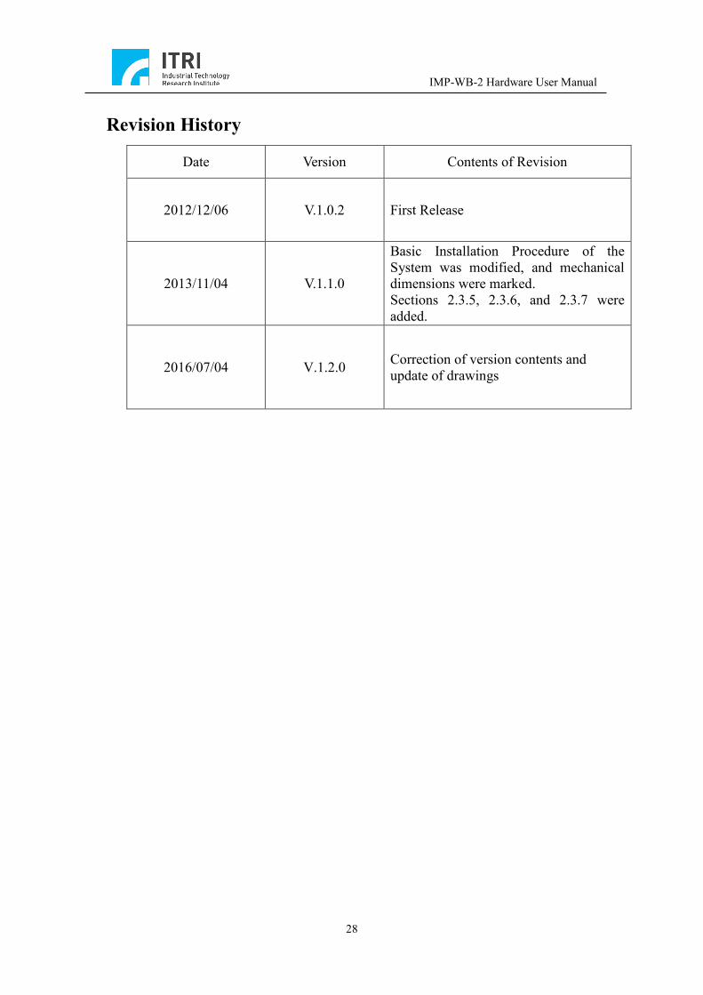
Revision History
Date Version Contents of Revision
2012/12/06 V.1.0.2 First Release
2013/11/04 V.1.1.0
Basic Installation Procedure of the System was modified, and mechanical dimensions were marked. Sections 2.3.5, 2.3.6, and 2.3.7 were added.
2016/07/04 V.1.2.0 Correction of version contents and update of drawings