imovr cascade & energize installation manual
TRANSCRIPT
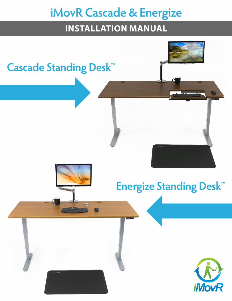
iMovR Cascade & EnergizeINSTALLATION MANUAL
Cascade Standing Desk™
Energize Standing Desk™
# Part name Picture Qty
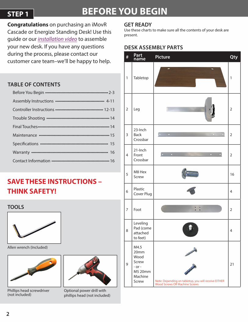
1 Tabletop 1
2 Leg 2
323-InchBackCrossbar
2
421-InchFrontCrossbar
2
5 M8 Hex Screw 16
6 Plastic Cover Plug 4
7 Foot 2
8
Leveling Pad (come attached to feet)
4
9
M4.5 20mm Wood Screw - or -M5 20mm Machine Screw Note: Depending on tabletop, you will receive EITHER
Wood Screws OR Machine Screws
21
2
Phillips head screwdriver (not included)
TOOLS
Optional power drill with phillips head (not included)
BEFORE YOU BEGIN
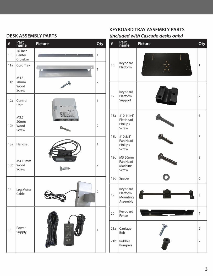
DESK ASSEMBLY PARTS
Before You Begin •••••••••••••••••••••••••••••••••••••••••••••••••• 2-3
Assembly Instructions ••••••••••••••••••••••••••••••••••••••• 4-11
Controller Instructions •••••••••••••••••••••••••••••••••••••• 12-13
Trouble Shooting •••••••••••••••••••••••••••••••••••••••••••••••••• 14
Final Touches ••••••••••••••••••••••••••••••••••••••••••••••••••••••••• 14
Maintenance •••••••••••••••••••••••••••••••••••••••••••••••••••••••• 15
Specifications •••••••••••••••••••••••••••••••••••••••••••••••••••••• 15
Warranty ••••••••••••••••••••••••••••••••••••••••••••••••••••••••••••• 16
Contact Information •••••••••••••••••••••••••••••••••••••••••••••• 16
TABLE OF CONTENTS
GET READYUse these charts to make sure all the contents of your desk are present.
SAVE THESE INSTRUCTIONS – THINK SAFETY!
Allen wrench (Included)
Congratulations on purchasing an iMovR Cascade or Energize Standing Desk! Use this guide or our installation video to assemble your new desk. If you have any questions during the process, please contact our customer care team–we’ll be happy to help.
STEP 1
# Part name Picture Qty
1026-InchCenterCrossbar
1
11a
11b
Cord Tray
M4.5 20mm Wood Screw
1
2
12a
12b
Control Unit
M3.5 20mm Wood Screw
1
2
13a
13b
Handset
M4 15mm Wood Screw
1
2
14 Leg Motor Cable 2
15 Power Supply 1
3
# Part name Picture Qty
16 Keyboard Platform 1
17Keyboard Platform Support
2
18a
18b
18c
18d
#10 1-1/4” Flat Head Phillips Screw
#10 5/8” Pan Head Phillips Screw
M5 20mm Pan Head Machine Screw
Spacer
6
7
8
6
19
Keyboard Platform Mounting Assembly
1
20 Keyboard Fence 1
21a
21b
Carriage Bolt
Rubber Bumpers
2
2
KEYBOARD TRAY ASSEMBLY PARTS (included with Cascade desks only)DESK ASSEMBLY PARTS
4
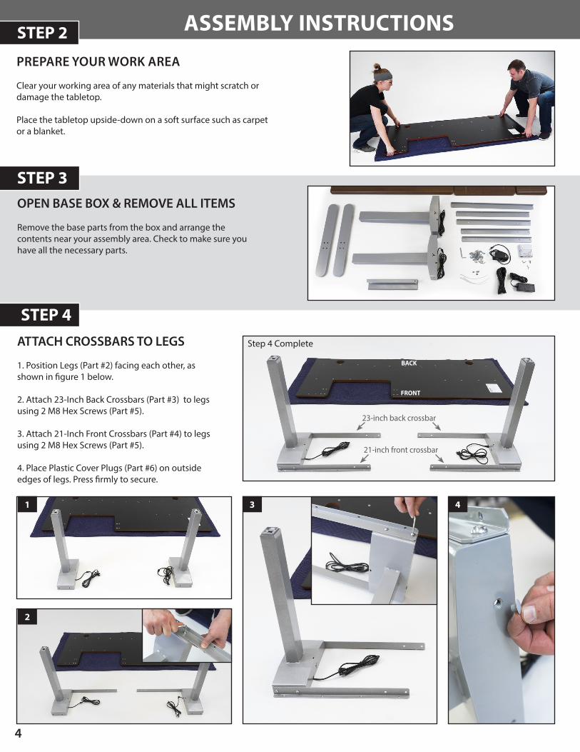
ASSEMBLY INSTRUCTIONS
PREPARE YOUR WORK AREA
Clear your working area of any materials that might scratch or damage the tabletop.
Place the tabletop upside-down on a soft surface such as carpet or a blanket.
OPEN BASE BOX & REMOVE ALL ITEMS
Remove the base parts from the box and arrange the contents near your assembly area. Check to make sure you have all the necessary parts.
STEP 3
STEP 4
STEP 2
ATTACH CROSSBARS TO LEGS
1. Position Legs (Part #2) facing each other, asshown in figure 1 below.
2. Attach 23-Inch Back Crossbars (Part #3) to legsusing 2 M8 Hex Screws (Part #5).
3. Attach 21-Inch Front Crossbars (Part #4) to legsusing 2 M8 Hex Screws (Part #5).
4. Place Plastic Cover Plugs (Part #6) on outsideedges of legs. Press firmly to secure.
2
4
Step 4 Complete
1 3
23-inch back crossbar
21-inch front crossbar
BACK
FRONT
STEP 5
5
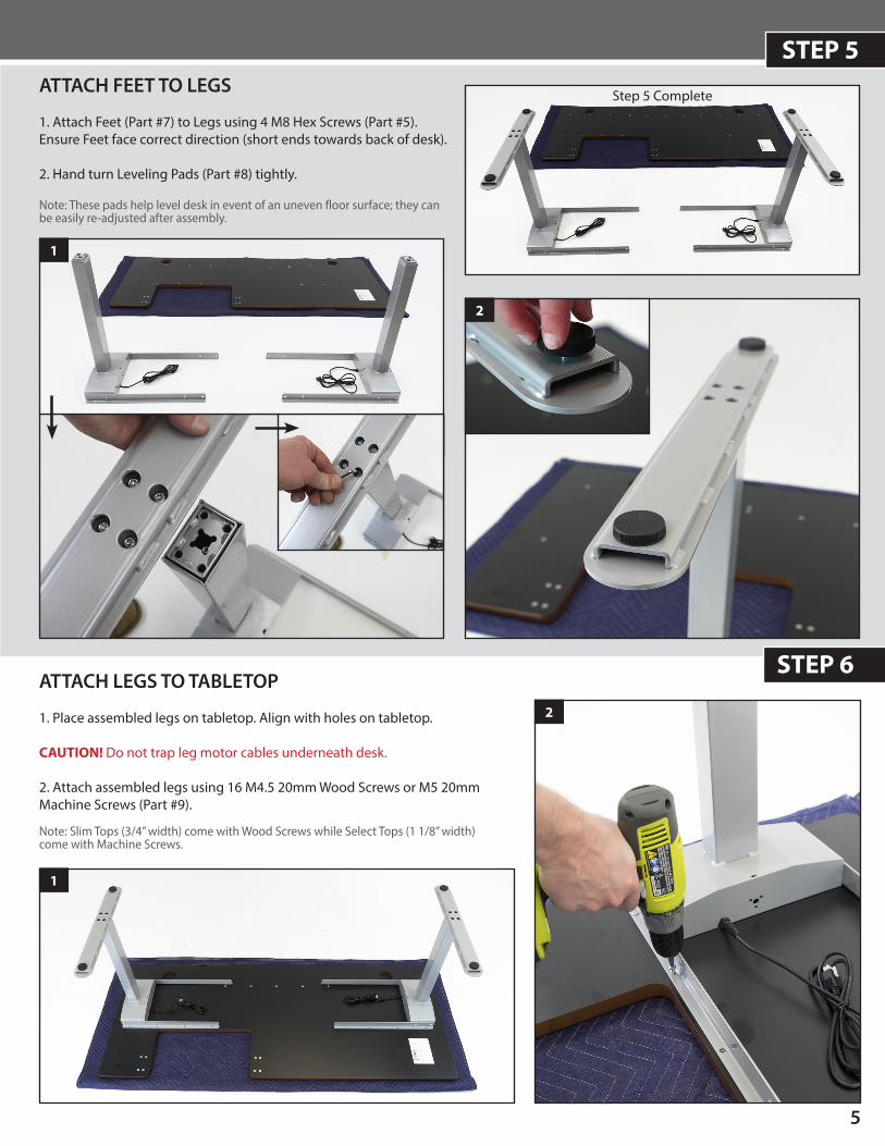
ATTACH LEGS TO TABLETOP
1. Place assembled legs on tabletop. Align with holes on tabletop.
CAUTION! Do not trap leg motor cables underneath desk.
2. Attach assembled legs using 16 M4.5 20mm Wood Screws or M5 20mmMachine Screws (Part #9).
Note: Slim Tops (3/4” width) come with Wood Screws while Select Tops (1 1/8” width) come with Machine Screws.
STEP 6
ATTACH FEET TO LEGS
1. Attach Feet (Part #7) to Legs using 4 M8 Hex Screws (Part #5).Ensure Feet face correct direction (short ends towards back of desk).
2. Hand turn Leveling Pads (Part #8) tightly.
Note: These pads help level desk in event of an uneven floor surface; they can be easily re-adjusted after assembly.
1
2
Step 5 Complete
1
2
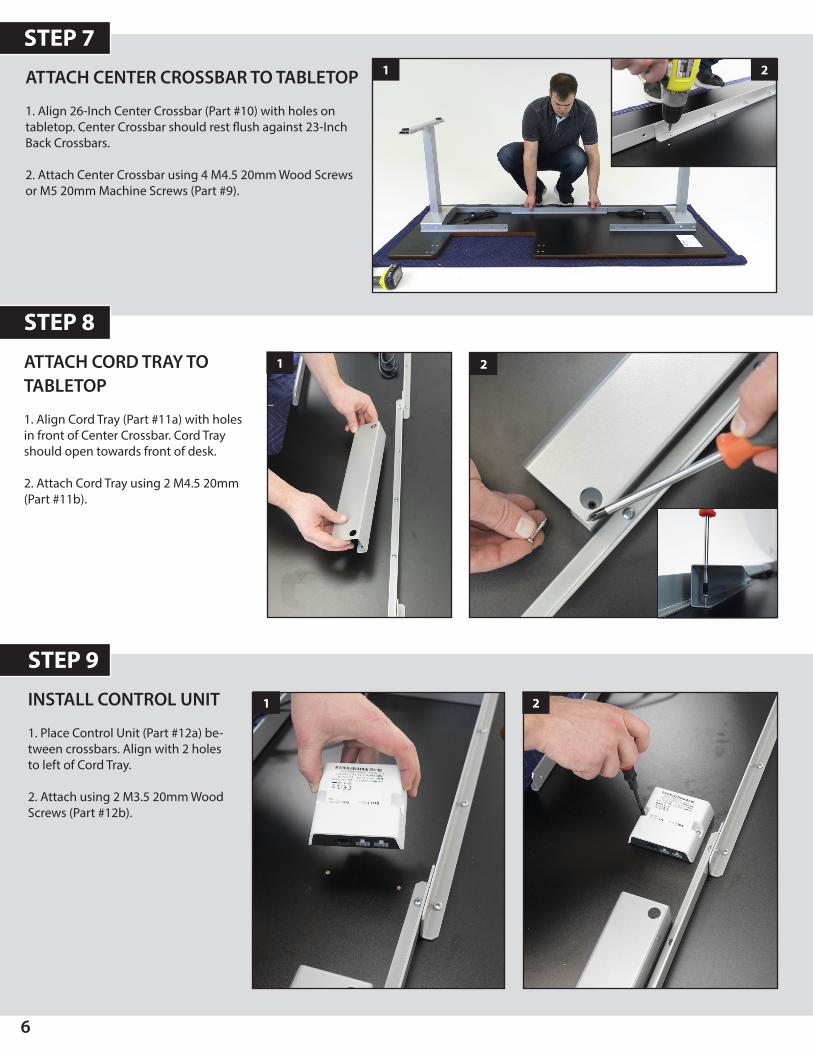
ATTACH CORD TRAY TO TABLETOP
1. Align Cord Tray (Part #11a) with holesin front of Center Crossbar. Cord Trayshould open towards front of desk.
2. Attach Cord Tray using 2 M4.5 20mm(Part #11b).
6
STEP 9
INSTALL CONTROL UNIT
1. Place Control Unit (Part #12a) be-tween crossbars. Align with 2 holesto left of Cord Tray.
2. Attach using 2 M3.5 20mm WoodScrews (Part #12b).
ATTACH CENTER CROSSBAR TO TABLETOP
1. Align 26-Inch Center Crossbar (Part #10) with holes ontabletop. Center Crossbar should rest flush against 23-InchBack Crossbars.
2. Attach Center Crossbar using 4 M4.5 20mm Wood Screwsor M5 20mm Machine Screws (Part #9).
STEP 7
STEP 8
1 2
1 2
1 2
7
STEP 10
If you’ve purchased a Cascade desk, now is time to INSTALL THE STEADYTYPE™ TILTING KEYBOARD PLATFORM.
If you’ve purchased an Energize desk, SKIP TO STEP 14.
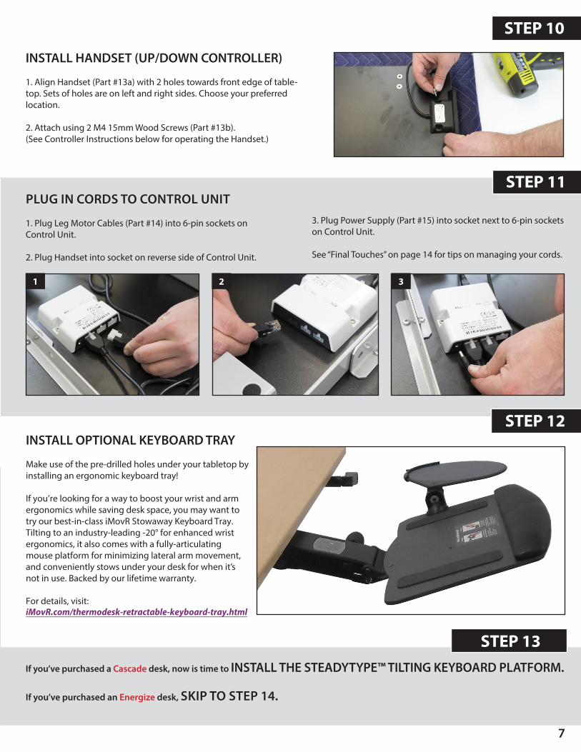
INSTALL OPTIONAL KEYBOARD TRAY
Make use of the pre-drilled holes under your tabletop by installing an ergonomic keyboard tray!
If you’re looking for a way to boost your wrist and arm ergonomics while saving desk space, you may want to try our best-in-class iMovR Stowaway Keyboard Tray. Tilting to an industry-leading -20° for enhanced wrist ergonomics, it also comes with a fully-articulating mouse platform for minimizing lateral arm movement, and conveniently stows under your desk for when it’s not in use. Backed by our lifetime warranty.
For details, visit:iMovR.com/thermodesk-retractable-keyboard-tray.html
INSTALL HANDSET (UP/DOWN CONTROLLER)
1. Align Handset (Part #13a) with 2 holes towards front edge of table-top. Sets of holes are on left and right sides. Choose your preferredlocation.
2. Attach using 2 M4 15mm Wood Screws (Part #13b).(See Controller Instructions below for operating the Handset.)
STEP 13
STEP 11PLUG IN CORDS TO CONTROL UNIT
1. Plug Leg Motor Cables (Part #14) into 6-pin sockets onControl Unit.
2. Plug Handset into socket on reverse side of Control Unit.
3. Plug Power Supply (Part #15) into socket next to 6-pin socketson Control Unit.
See “Final Touches” on page 14 for tips on managing your cords.
STEP 12
1 2 3
8
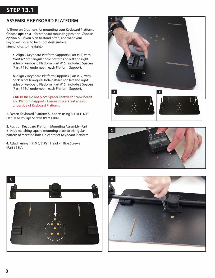
ASSEMBLE KEYBOARD PLATFORM
1. There are 2 options for mounting your Keyboard Platform.Choose option a – for standard mounting position. Chooseoption b – if you plan to stand often, and want yourkeyboard closer to height of desk surface.(See photos to the right.)
a. Align 2 Keyboard Platform Supports (Part #17) withfront set of triangular hole patterns on left and rightsides of Keyboard Platform (Part #16); include 3 Spacers(Part # 18d) underneath each Platform Support.
b. Align 2 Keyboard Platform Supports (Part #17) withback set of triangular hole patterns on left and rightsides of Keyboard Platform (Part #16); include 3 Spacers(Part # 18d) underneath each Platform Support.
CAUTION! Do not place Spacers between screw heads and Platform Supports. Ensure Spacers rest against underside of Keyboard Platform.
2. Fasten Keyboard Platform Supports using 3 #10 1-1/4” Flat Head Phillips Screws (Part #18a).
3. Position Keyboard Platform Mounting Assembly (Part#19) by matching square mounting plate to triangularpattern of recessed holes in center of Keyboard Platform.
4. Attach using 4 #10 5/8” Pan Head Phillips Screws(Part #18b).
1
STEP 13.1
3 4
2
a b
9
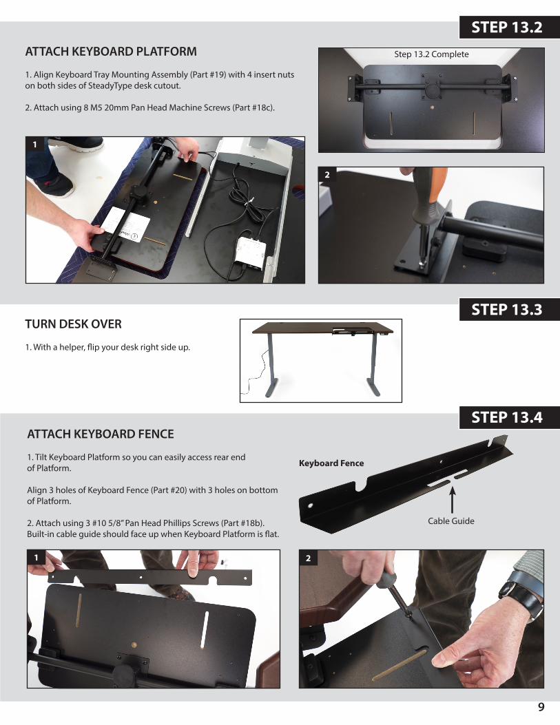
ATTACH KEYBOARD FENCE
1. Tilt Keyboard Platform so you can easily access rear endof Platform.
Align 3 holes of Keyboard Fence (Part #20) with 3 holes on bottom of Platform.
2. Attach using 3 #10 5/8” Pan Head Phillips Screws (Part #18b).Built-in cable guide should face up when Keyboard Platform is flat.
TURN DESK OVER
1. With a helper, flip your desk right side up.
STEP 13.2
STEP 13.4
2
Keyboard Fence
Cable Guide
ATTACH KEYBOARD PLATFORM
1. Align Keyboard Tray Mounting Assembly (Part #19) with 4 insert nutson both sides of SteadyType desk cutout.
2. Attach using 8 M5 20mm Pan Head Machine Screws (Part #18c).
1
2
Step 13.2 Complete
1
STEP 13.3
10
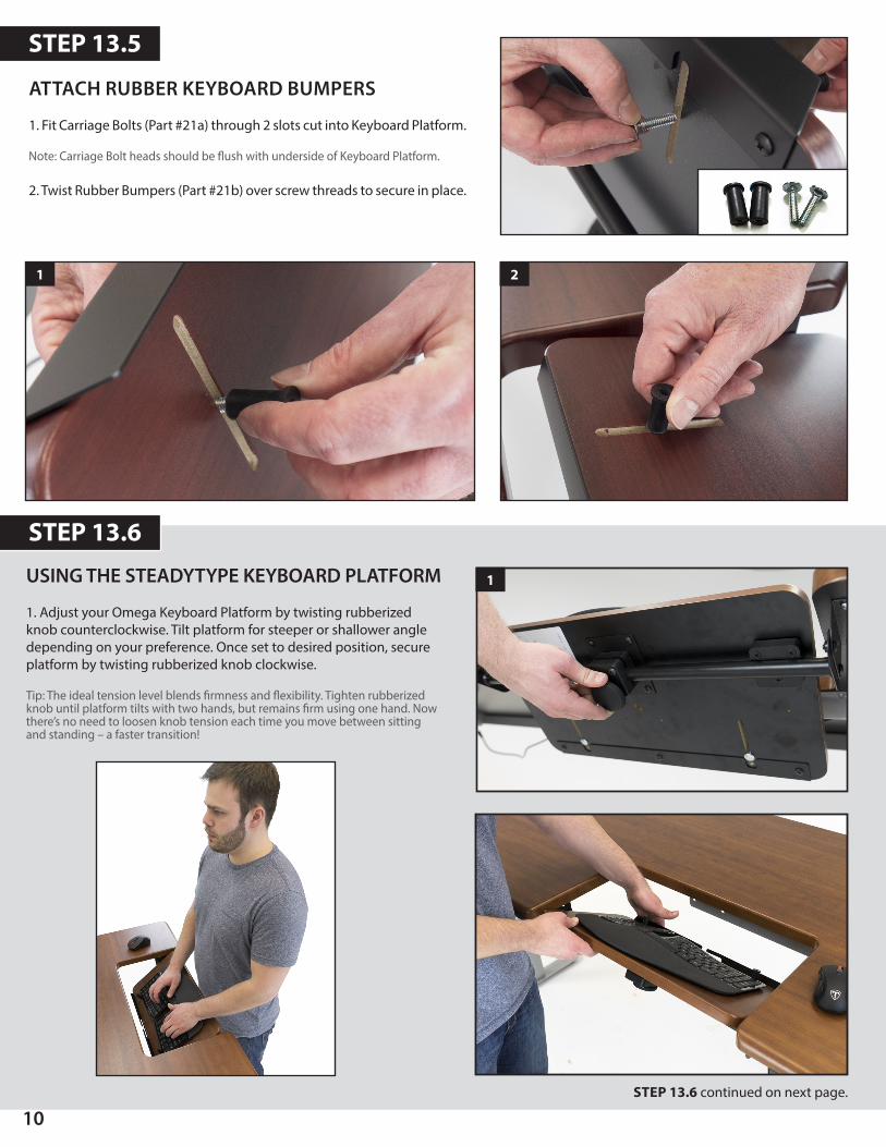
USING THE STEADYTYPE KEYBOARD PLATFORM
1. Adjust your Omega Keyboard Platform by twisting rubberizedknob counterclockwise. Tilt platform for steeper or shallower angledepending on your preference. Once set to desired position, secureplatform by twisting rubberized knob clockwise.
Tip: The ideal tension level blends firmness and flexibility. Tighten rubberized knob until platform tilts with two hands, but remains firm using one hand. Now there’s no need to loosen knob tension each time you move between sitting and standing – a faster transition!
ATTACH RUBBER KEYBOARD BUMPERS
1. Fit Carriage Bolts (Part #21a) through 2 slots cut into Keyboard Platform.
Note: Carriage Bolt heads should be flush with underside of Keyboard Platform.
2. Twist Rubber Bumpers (Part #21b) over screw threads to secure in place.
STEP 13.5
STEP 13.6
STEP 13.6 continued on next page.
1
1 2
11
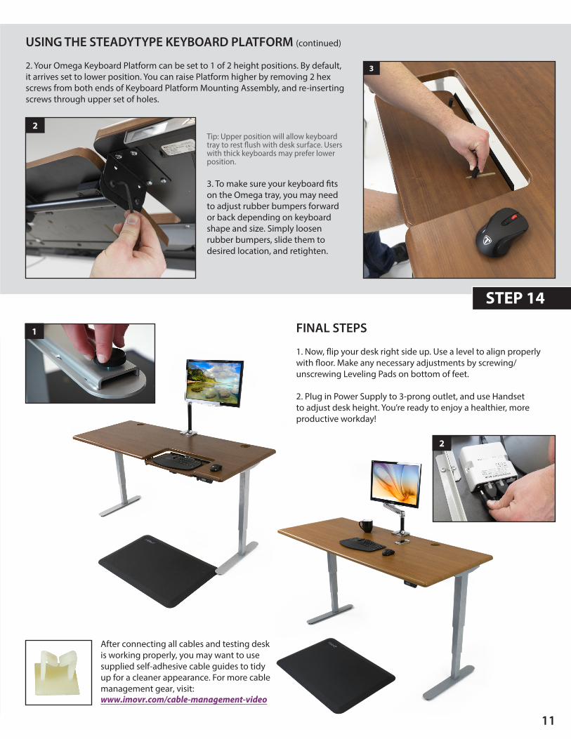
FINAL STEPS
1. Now, flip your desk right side up. Use a level to align properlywith floor. Make any necessary adjustments by screwing/unscrewing Leveling Pads on bottom of feet.
2. Plug in Power Supply to 3-prong outlet, and use Handsetto adjust desk height. You’re ready to enjoy a healthier, moreproductive workday!
STEP 14
USING THE STEADYTYPE KEYBOARD PLATFORM (continued)
2. Your Omega Keyboard Platform can be set to 1 of 2 height positions. By default,it arrives set to lower position. You can raise Platform higher by removing 2 hexscrews from both ends of Keyboard Platform Mounting Assembly, and re-insertingscrews through upper set of holes.
Tip: Upper position will allow keyboard tray to rest flush with desk surface. Users with thick keyboards may prefer lower position.
3. To make sure your keyboard fitson the Omega tray, you may needto adjust rubber bumpers forwardor back depending on keyboardshape and size. Simply loosenrubber bumpers, slide them todesired location, and retighten.
2
3
1
2
After connecting all cables and testing desk is working properly, you may want to use supplied self-adhesive cable guides to tidy up for a cleaner appearance. For more cable management gear, visit:www.imovr.com/cable-management-video
CONTROLLER INSTRUCTIONS
12
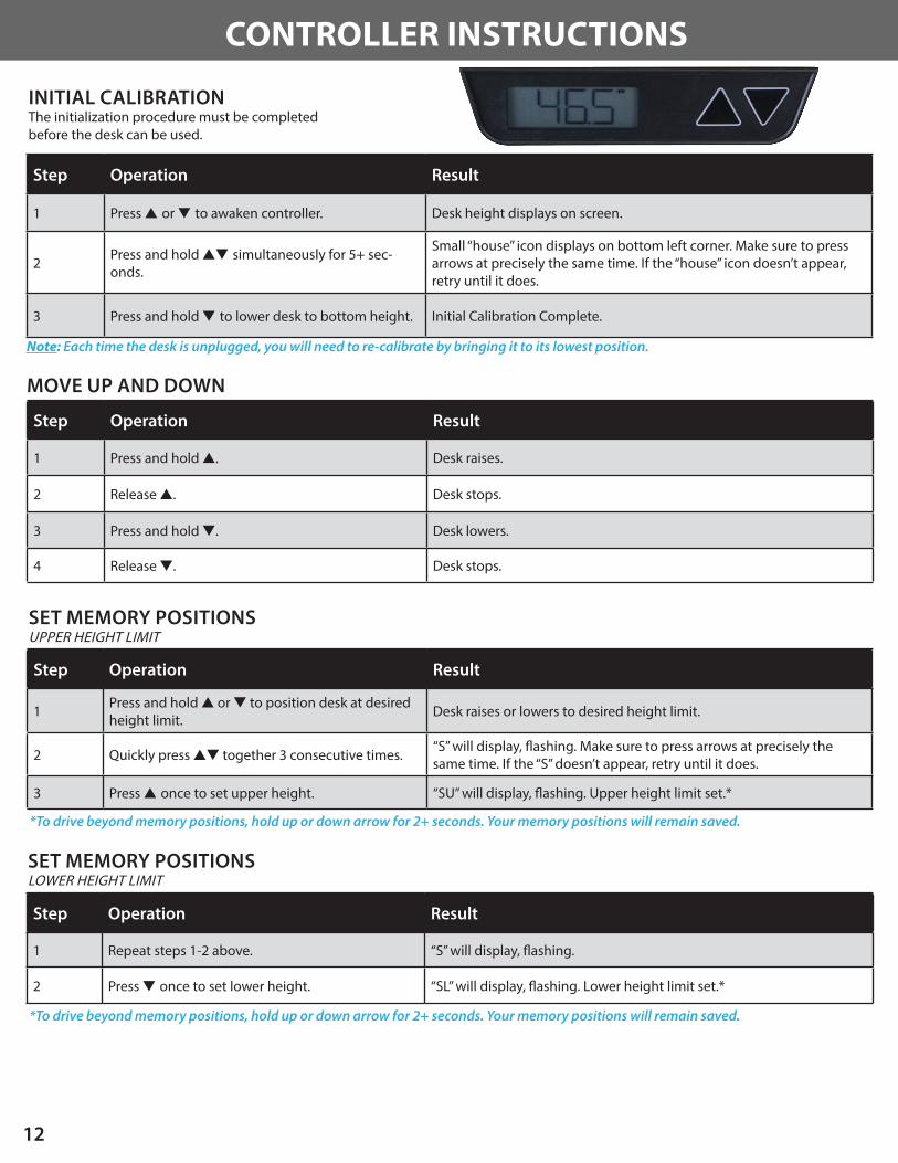
INITIAL CALIBRATIONThe initialization procedure must be completed before the desk can be used.
MOVE UP AND DOWN
Step Operation Result
1 Press s or t to awaken controller. Desk height displays on screen.
2 Press and hold st simultaneously for 5+ sec-onds.
Small “house” icon displays on bottom left corner. Make sure to press arrows at precisely the same time. If the “house” icon doesn’t appear, retry until it does.
3 Press and hold t to lower desk to bottom height. Initial Calibration Complete.
Note: Each time the desk is unplugged, you will need to re-calibrate by bringing it to its lowest position.
Step Operation Result
1 Press and hold s. Desk raises.
2 Release s. Desk stops.
3 Press and hold t. Desk lowers.
4 Release t. Desk stops.
SET MEMORY POSITIONSUPPER HEIGHT LIMIT
Step Operation Result
1 Press and hold s or t to position desk at desired height limit.
Desk raises or lowers to desired height limit.
2 Quickly press st together 3 consecutive times.“S” will display, flashing. Make sure to press arrows at precisely the same time. If the “S” doesn’t appear, retry until it does.
3 Press s once to set upper height. “SU” will display, flashing. Upper height limit set.*
*To drive beyond memory positions, hold up or down arrow for 2+ seconds. Your memory positions will remain saved.
Step Operation Result
1 Repeat steps 1-2 above. “S” will display, flashing.
2 Press t once to set lower height. “SL” will display, flashing. Lower height limit set.*
*To drive beyond memory positions, hold up or down arrow for 2+ seconds. Your memory positions will remain saved.
SET MEMORY POSITIONSLOWER HEIGHT LIMIT
13
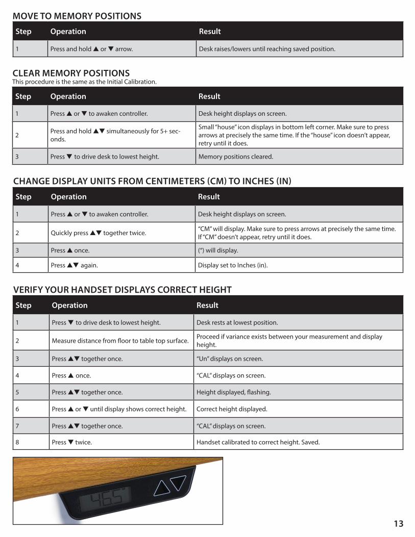
CLEAR MEMORY POSITIONS
Step Operation Result
1 Press s or t to awaken controller. Desk height displays on screen.
2 Press and hold st simultaneously for 5+ sec-onds.
Small “house” icon displays in bottom left corner. Make sure to press arrows at precisely the same time. If the “house” icon doesn’t appear, retry until it does.
3 Press t to drive desk to lowest height. Memory positions cleared.
Step Operation Result
1 Press s or t to awaken controller. Desk height displays on screen.
2 Quickly press st together twice.“CM” will display. Make sure to press arrows at precisely the same time. If “CM” doesn’t appear, retry until it does.
3 Press s once. (“) will display.
4 Press st again. Display set to Inches (in).
CHANGE DISPLAY UNITS FROM CENTIMETERS (CM) TO INCHES (IN)
MOVE TO MEMORY POSITIONS
Step Operation Result
1 Press and hold s or t arrow. Desk raises/lowers until reaching saved position.
This procedure is the same as the Initial Calibration.
Step Operation Result
1 Press t to drive desk to lowest height. Desk rests at lowest position.
2 Measure distance from floor to table top surface. Proceed if variance exists between your measurement and display height.
3 Press st together once. “Un” displays on screen.
4 Press s once. “CAL” displays on screen.
5 Press st together once. Height displayed, flashing.
6 Press s or t until display shows correct height. Correct height displayed.
7 Press st together once. “CAL” displays on screen.
8 Press t twice. Handset calibrated to correct height. Saved.
VERIFY YOUR HANDSET DISPLAYS CORRECT HEIGHT
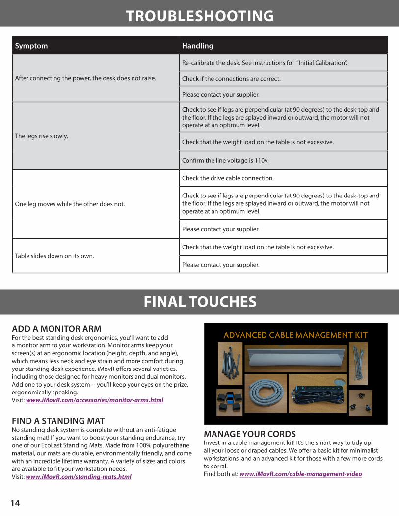
MANAGE YOUR CORDSInvest in a cable management kit! It’s the smart way to tidy up all your loose or draped cables. We offer a basic kit for minimalist workstations, and an advanced kit for those with a few more cords to corral. Find both at: www.iMovR.com/cable-management-video
Symptom Handling
After connecting the power, the desk does not raise.
Re-calibrate the desk. See instructions for “Initial Calibration”.
Check if the connections are correct.
Please contact your supplier.
The legs rise slowly.
Check to see if legs are perpendicular (at 90 degrees) to the desk-top and the floor. If the legs are splayed inward or outward, the motor will not operate at an optimum level.
Check that the weight load on the table is not excessive.
Confirm the line voltage is 110v.
One leg moves while the other does not.
Check the drive cable connection.
Check to see if legs are perpendicular (at 90 degrees) to the desk-top and the floor. If the legs are splayed inward or outward, the motor will not operate at an optimum level.
Please contact your supplier.
Table slides down on its own.Check that the weight load on the table is not excessive.
Please contact your supplier.
14
ADD A MONITOR ARMFor the best standing desk ergonomics, you’ll want to add a monitor arm to your workstation. Monitor arms keep your screen(s) at an ergonomic location (height, depth, and angle), which means less neck and eye strain and more comfort during your standing desk experience. iMovR offers several varieties, including those designed for heavy monitors and dual monitors. Add one to your desk system -- you’ll keep your eyes on the prize, ergonomically speaking. Visit: www.iMovR.com/accessories/monitor-arms.html
FIND A STANDING MATNo standing desk system is complete without an anti-fatigue standing mat! If you want to boost your standing endurance, try one of our EcoLast Standing Mats. Made from 100% polyurethane material, our mats are durable, environmentally friendly, and come with an incredible lifetime warranty. A variety of sizes and colors are available to fit your workstation needs. Visit: www.iMovR.com/standing-mats.html
TROUBLESHOOTING
FINAL TOUCHES
15
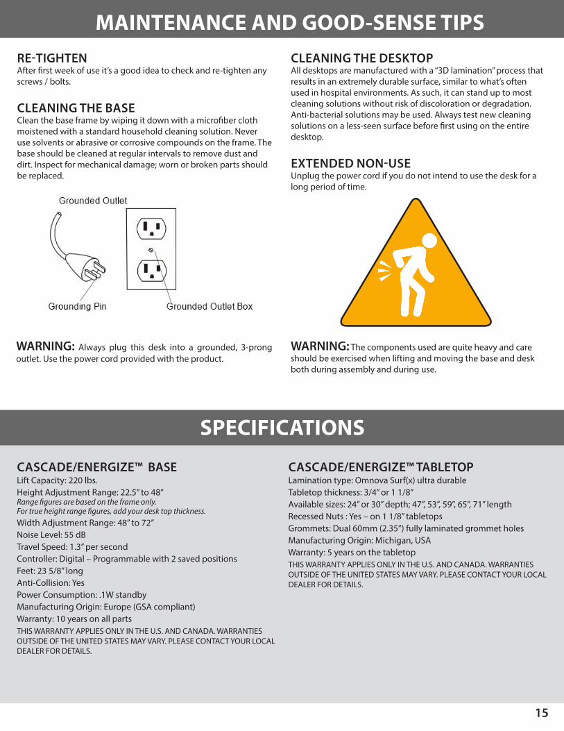
RE-TIGHTENAfter first week of use it’s a good idea to check and re-tighten any screws / bolts.
CLEANING THE BASE Clean the base frame by wiping it down with a microfiber cloth moistened with a standard household cleaning solution. Never use solvents or abrasive or corrosive compounds on the frame. The base should be cleaned at regular intervals to remove dust and dirt. Inspect for mechanical damage; worn or broken parts should be replaced.
CLEANING THE DESKTOP All desktops are manufactured with a “3D lamination” process that results in an extremely durable surface, similar to what’s often used in hospital environments. As such, it can stand up to most cleaning solutions without risk of discoloration or degradation. Anti-bacterial solutions may be used. Always test new cleaning solutions on a less-seen surface before first using on the entire desktop.
EXTENDED NON-USE Unplug the power cord if you do not intend to use the desk for a long period of time.
MAINTENANCE AND GOOD-SENSE TIPS
SPECIFICATIONS
WARNING: Always plug this desk into a grounded, 3-prong outlet. Use the power cord provided with the product.
WARNING: The components used are quite heavy and careshould be exercised when lifting and moving the base and desk both during assembly and during use.
CASCADE/ENERGIZE™ BASELift Capacity: 220 lbs.Height Adjustment Range: 22.5” to 48” Range figures are based on the frame only. For true height range figures, add your desk top thickness.Width Adjustment Range: 48” to 72” Noise Level: 55 dBTravel Speed: 1.3” per secondController: Digital – Programmable with 2 saved positionsFeet: 23 5/8” longAnti-Collision: YesPower Consumption: .1W standbyManufacturing Origin: Europe (GSA compliant)Warranty: 10 years on all partsTHIS WARRANTY APPLIES ONLY IN THE U.S. AND CANADA. WARRANTIES OUTSIDE OF THE UNITED STATES MAY VARY. PLEASE CONTACT YOUR LOCAL DEALER FOR DETAILS.
CASCADE/ENERGIZE™ TABLETOPLamination type: Omnova Surf(x) ultra durableTabletop thickness: 3/4” or 1 1/8” Available sizes: 24” or 30” depth; 47”, 53”, 59”, 65”, 71” lengthRecessed Nuts : Yes – on 1 1/8” tabletopsGrommets: Dual 60mm (2.35”) fully laminated grommet holesManufacturing Origin: Michigan, USAWarranty: 5 years on the tabletopTHIS WARRANTY APPLIES ONLY IN THE U.S. AND CANADA. WARRANTIES OUTSIDE OF THE UNITED STATES MAY VARY. PLEASE CONTACT YOUR LOCAL DEALER FOR DETAILS.
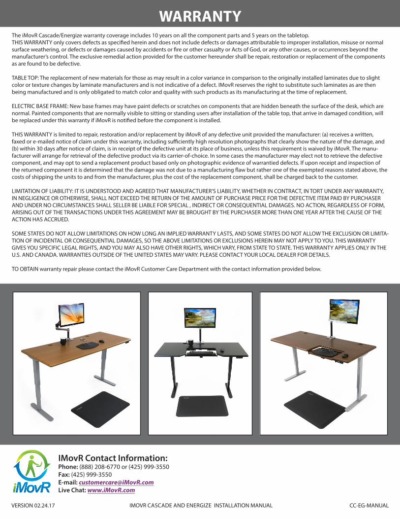
WARRANTYThe iMovR Cascade/Energize warranty coverage includes 10 years on all the component parts and 5 years on the tabletop.THIS WARRANTY only covers defects as specified herein and does not include defects or damages attributable to improper installation, misuse or normal surface weathering, or defects or damages caused by accidents or fire or other casualty or Acts of God, or any other causes, or occurrences beyond the manufacturer’s control. The exclusive remedial action provided for the customer hereunder shall be repair, restoration or replacement of the components as are found to be defective.
TABLE TOP: The replacement of new materials for those as may result in a color variance in comparison to the originally installed laminates due to slight color or texture changes by laminate manufacturers and is not indicative of a defect. IMovR reserves the right to substitute such laminates as are then being manufactured and is only obligated to match color and quality with such products as its manufacturing at the time of replacement.
ELECTRIC BASE FRAME: New base frames may have paint defects or scratches on components that are hidden beneath the surface of the desk, which are normal. Painted components that are normally visible to sitting or standing users after installation of the table top, that arrive in damaged condition, will be replaced under this warranty if iMovR is notified before the component is installed.
THIS WARRANTY is limited to repair, restoration and/or replacement by iMovR of any defective unit provided the manufacturer: (a) receives a written, faxed or e-mailed notice of claim under this warranty, including sufficiently high resolution photographs that clearly show the nature of the damage, and (b) within 30 days after notice of claim, is in receipt of the defective unit at its place of business, unless this requirement is waived by iMovR. The manu-facturer will arrange for retrieval of the defective product via its carrier-of-choice. In some cases the manufacturer may elect not to retrieve the defective component, and may opt to send a replacement product based only on photographic evidence of warrantied defects. If upon receipt and inspection of the returned component it is determined that the damage was not due to a manufacturing flaw but rather one of the exempted reasons stated above, the costs of shipping the units to and from the manufacturer, plus the cost of the replacement component, shall be charged back to the customer.
LIMITATION OF LIABILITY: IT IS UNDERSTOOD AND AGREED THAT MANUFACTURER’S LIABILITY, WHETHER IN CONTRACT, IN TORT UNDER ANY WARRANTY, IN NEGLIGENCE OR OTHERWISE, SHALL NOT EXCEED THE RETURN OF THE AMOUNT OF PURCHASE PRICE FOR THE DEFECTIVE ITEM PAID BY PURCHASER AND UNDER NO CIRCUMSTANCES SHALL SELLER BE LIABLE FOR SPECIAL , INDIRECT OR CONSEQUENTIAL DAMAGES. NO ACTION, REGARDLESS OF FORM, ARISING OUT OF THE TRANSACTIONS UNDER THIS AGREEMENT MAY BE BROUGHT BY THE PURCHASER MORE THAN ONE YEAR AFTER THE CAUSE OF THE ACTION HAS ACCRUED.
SOME STATES DO NOT ALLOW LIMITATIONS ON HOW LONG AN IMPLIED WARRANTY LASTS, AND SOME STATES DO NOT ALLOW THE EXCLUSION OR LIMITA-TION OF INCIDENTAL OR CONSEQUENTIAL DAMAGES, SO THE ABOVE LIMITATIONS OR EXCLUSIONS HEREIN MAY NOT APPLY TO YOU. THIS WARRANTY GIVES YOU SPECIFIC LEGAL RIGHTS, AND YOU MAY ALSO HAVE OTHER RIGHTS, WHICH VARY, FROM STATE TO STATE. THIS WARRANTY APPLIES ONLY IN THE U.S. AND CANADA. WARRANTIES OUTSIDE OF THE UNITED STATES MAY VARY. PLEASE CONTACT YOUR LOCAL DEALER FOR DETAILS.
TO OBTAIN warranty repair please contact the iMovR Customer Care Department with the contact information provided below.
IMovR Contact Information:Phone: (888) 208-6770 or (425) 999-3550 Fax: (425) 999-3550E-mail: [email protected] Live Chat: www.iMovR.com
VERSION 02.24.17 IMOVR CASCADE AND ENERGIZE INSTALLATION MANUAL CC-EG-MANUAL