imc-700 catalog56 catalog - sales service parts rentals
TRANSCRIPT

PRODUCT CATALOGENGINE HEATERS • OIL HEATERS • CONTROLS • ACCESSORIES
IMC-700

HEATER INSTALLATION• Page 22 (Thermosiphon)• Page 51 (In-block)
HOW TO SPECIFY AN ENGINE HEATER
• Page 54
CONVERSION CHARTS
• Page 54
CUSTOM PRODUCTSCall for information on:
• Wiring Harnesses• APUs• Forced Circulation Heating
Systems• Other Specialty Products
1
4
3
2
TABLE OF CONTENTS
PAGES 4 - 5• HOTfl ow® Engine Heaters CTM, CSM Models
PAGES 6 - 17• Thermosiphon Engine Heaters Weathertight Design TPS, CB, CL, WL, SB, SL Models
PAGES 18 - 21• Thermosiphon Engine Heaters Hazardous Location EE Models
PAGES 24 - 29• Lube Oil Heaters (AC and DC)• Industrial Immersion Heaters Thread-in and Threadless Models
PAGES 31 - 36• Remote Thermostats for Lube Oil Heaters• Temperature Controls for Thermosiphon Engine Heaters• Complete Control Systems
PAGES 38 - 40• Battery Warming Pads & Accessories• Blanket Style Battery Warmers• Silicone Hot Pads
PAGES 42 - 53• In-block Heaters• Electrical Cords for In-block Heaters• Thermocords• Flush Mount Kits and Accessories
5

SECTION 1
HOTfl ow® and THERMOSIPHON ENGINE HEATERS
4 Customer Service: 509.536.8660 hotstart.com
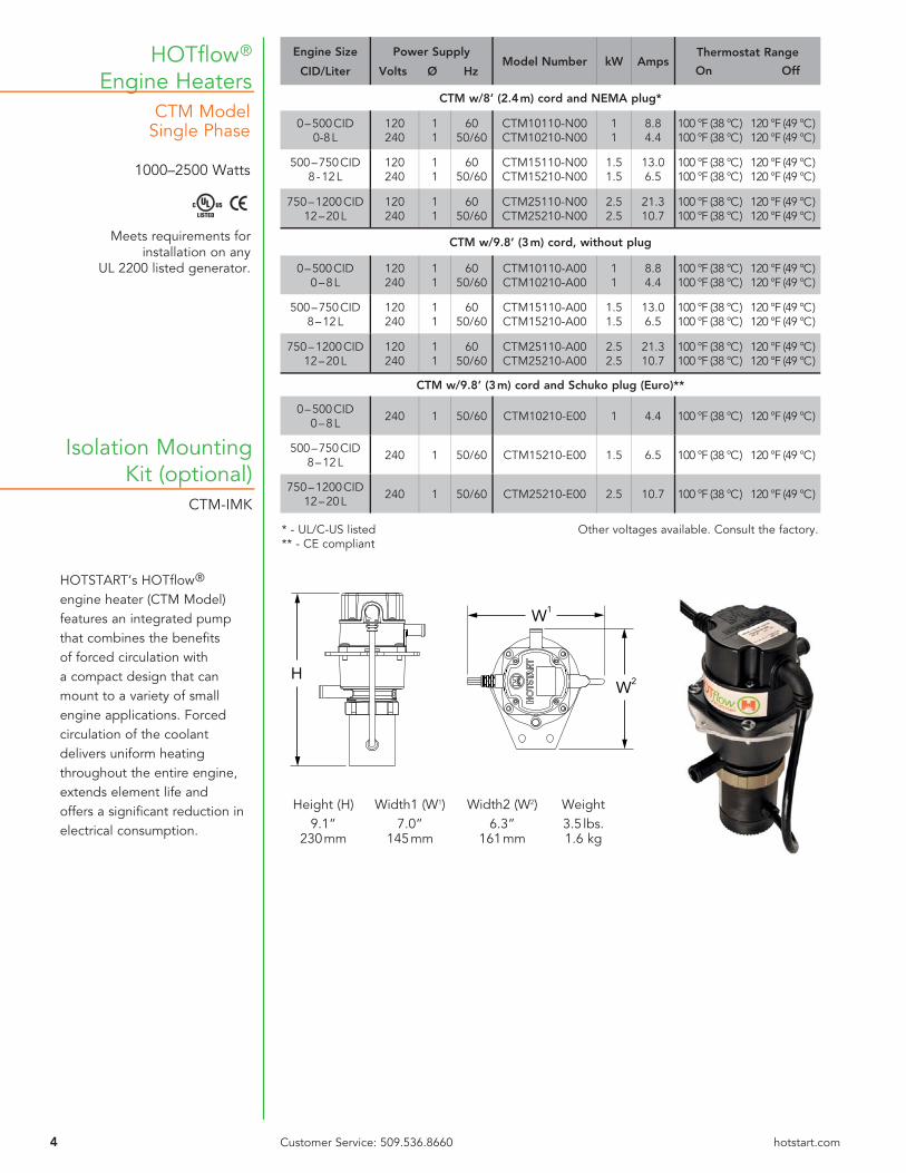
HOTfl ow®
Engine HeatersCTM Model
Single Phase
1000–2500 Watts
H
W1
W2
HOTSTART’s HOTfl ow® engine heater (CTM Model) features an integrated pump that combines the benefi ts of forced circulation with a compact design that can mount to a variety of small engine applications. Forced circulation of the coolant delivers uniform heating throughout the entire engine, extends element life and offers a signifi cant reduction in electrical consumption.
Isolation MountingKit (optional)
CTM-IMK
Height (H) Width1 (W1) Width2 (W2) Weight 9.1” 7.0” 6.3” 3.5 lbs. 230 mm 145 mm 161 mm 1.6 kg
Engine Size
CID/Liter
Power Supply
Volts Ø HzModel Number kW Amps
Thermostat Range
On Off
CTM w/8’ (2.4 m) cord and NEMA plug*
0 – 500 CID0-8 L
120240
11
6050/60
CTM10110-N00CTM10210-N00
11
8.84.4
100 °F (38 °C) 120 °F (49 °C) 100 °F (38 °C) 120 °F (49 °C)
500 – 750 CID8 - 12 L
120240
11
6050/60
CTM15110-N00CTM15210-N00
1.51.5
13.06.5
100 °F (38 °C) 120 °F (49 °C) 100 °F (38 °C) 120 °F (49 °C)
750 – 1200 CID12 – 20 L
120240
11
6050/60
CTM25110-N00CTM25210-N00
2.52.5
21.310.7
100 °F (38 °C) 120 °F (49 °C) 100 °F (38 °C) 120 °F (49 °C)
CTM w/9.8’ (3 m) cord, without plug
0 – 500 CID0 – 8 L
120240
11
6050/60
CTM10110-A00CTM10210-A00
11
8.84.4
100 °F (38 °C) 120 °F (49 °C) 100 °F (38 °C) 120 °F (49 °C)
500 – 750 CID8 – 12 L
120240
11
6050/60
CTM15110-A00CTM15210-A00
1.51.5
13.06.5
100 °F (38 °C) 120 °F (49 °C) 100 °F (38 °C) 120 °F (49 °C)
750 – 1200 CID12 – 20 L
120240
11
6050/60
CTM25110-A00CTM25210-A00
2.52.5
21.310.7
100 °F (38 °C) 120 °F (49 °C) 100 °F (38 °C) 120 °F (49 °C)
CTM w/9.8’ (3 m) cord and Schuko plug (Euro)**
0 – 500 CID0 – 8 L 240 1 50/60 CTM10210-E00 1 4.4 100 °F (38 °C) 120 °F (49 °C)
500 – 750 CID8 – 12 L 240 1 50/60 CTM15210-E00 1.5 6.5 100 °F (38 °C) 120 °F (49 °C)
750 – 1200 CID12 – 20 L 240 1 50/60 CTM25210-E00 2.5 10.7 100 °F (38 °C) 120 °F (49 °C)
* - UL/C-US listed Other voltages available. Consult the factory.** - CE compliant
Meets requirements for installation on any
UL 2200 listed generator.
5Customer Service: 509.536.8660 hotstart.com
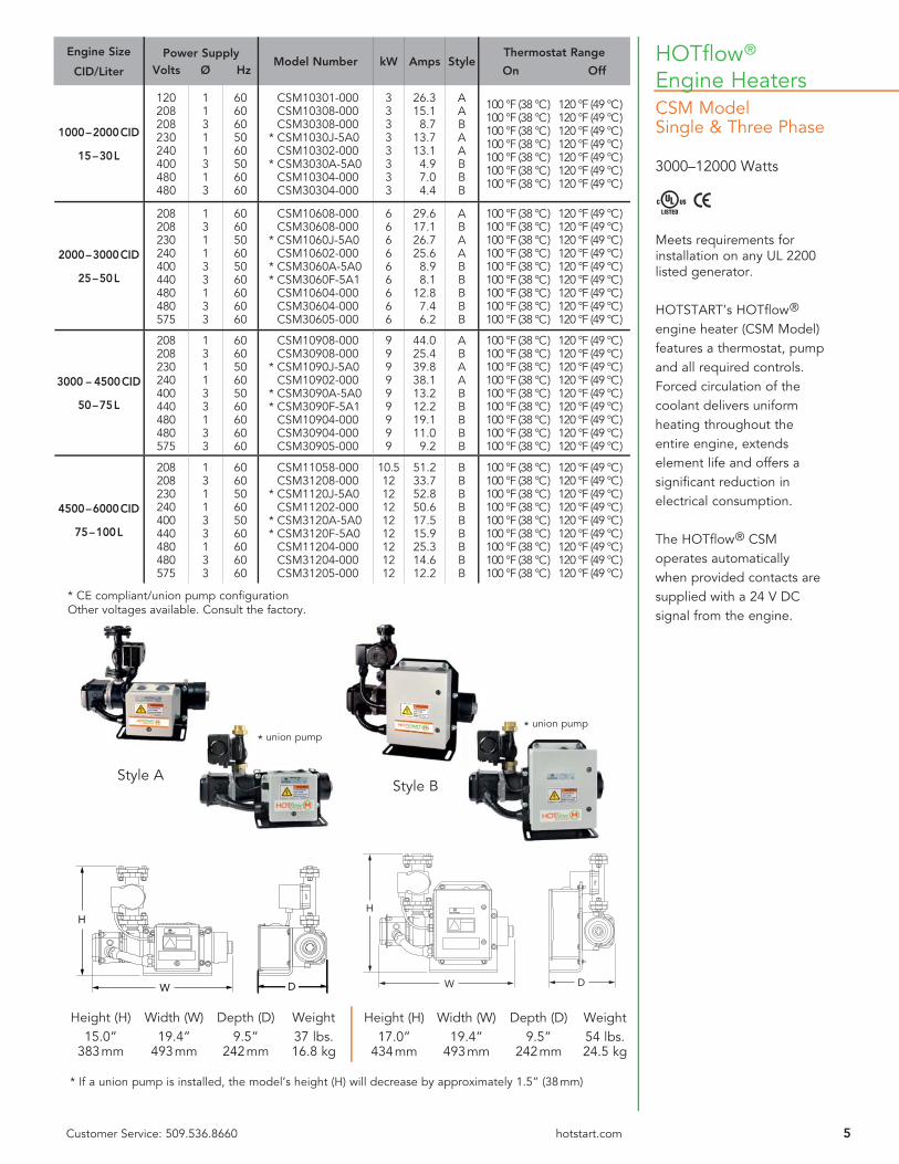
HOTfl ow®
Engine HeatersCSM ModelSingle & Three Phase
3000–12000 Watts
Meets requirements for installation on any UL 2200 listed generator.
HOTSTART’s HOTfl ow® engine heater (CSM Model) features a thermostat, pump and all required controls. Forced circulation of the coolant delivers uniform heating throughout the entire engine, extends element life and offers a signifi cant reduction in electrical consumption.
The HOTfl ow® CSM operates automatically when provided contacts are supplied with a 24 V DC signal from the engine.
Engine Size
CID/Liter
Power Supply Volts Ø Hz
Model Number kW Amps StyleThermostat Range
On Off
1000 – 2000 CID
15 – 30 L
120208208230240400480480
11311313
6060605060506060
CSM10301-000 CSM10308-000 CSM30308-000
* CSM1030J-5A0 CSM10302-000
* CSM3030A-5A0 CSM10304-000 CSM30304-000
33333333
26.315.18.7
13.713.14.97.04.4
AABAABBB
100 °F (38 °C) 120 °F (49 °C) 100 °F (38 °C) 120 °F (49 °C) 100 °F (38 °C) 120 °F (49 °C) 100 °F (38 °C) 120 °F (49 °C) 100 °F (38 °C) 120 °F (49 °C) 100 °F (38 °C) 120 °F (49 °C) 100 °F (38 °C) 120 °F (49 °C)
2000 – 3000 CID
25 – 50 L
208208230240400440480480575
131133133
606050605060606060
CSM10608-000 CSM30608-000
* CSM1060J-5A0 CSM10602-000
* CSM3060A-5A0* CSM3060F-5A1
CSM10604-000 CSM30604-000 CSM30605-000
666666666
29.617.126.725.68.98.1
12.87.46.2
ABAABBBBB
100 °F (38 °C) 120 °F (49 °C) 100 °F (38 °C) 120 °F (49 °C) 100 °F (38 °C) 120 °F (49 °C) 100 °F (38 °C) 120 °F (49 °C) 100 °F (38 °C) 120 °F (49 °C) 100 °F (38 °C) 120 °F (49 °C) 100 °F (38 °C) 120 °F (49 °C) 100 °F (38 °C) 120 °F (49 °C) 100 °F (38 °C) 120 °F (49 °C)
3000 – 4500 CID
50 – 75 L
208208230240400440480480575
131133133
606050605060606060
CSM10908-000 CSM30908-000
* CSM1090J-5A0 CSM10902-000
* CSM3090A-5A0* CSM3090F-5A1
CSM10904-000 CSM30904-000 CSM30905-000
999999999
44.025.439.838.113.212.219.111.09.2
ABAABBBBB
100 °F (38 °C) 120 °F (49 °C) 100 °F (38 °C) 120 °F (49 °C) 100 °F (38 °C) 120 °F (49 °C) 100 °F (38 °C) 120 °F (49 °C) 100 °F (38 °C) 120 °F (49 °C) 100 °F (38 °C) 120 °F (49 °C) 100 °F (38 °C) 120 °F (49 °C) 100 °F (38 °C) 120 °F (49 °C) 100 °F (38 °C) 120 °F (49 °C)
4500 – 6000 CID
75 – 100 L
208208230240400440480480575
131133133
606050605060606060
CSM11058-000 CSM31208-000
* CSM1120J-5A0 CSM11202-000
* CSM3120A-5A0* CSM3120F-5A0
CSM11204-000 CSM31204-000 CSM31205-000
10.51212121212121212
51.233.752.850.617.515.925.314.612.2
BBBBBBBBB
100 °F (38 °C) 120 °F (49 °C) 100 °F (38 °C) 120 °F (49 °C) 100 °F (38 °C) 120 °F (49 °C) 100 °F (38 °C) 120 °F (49 °C) 100 °F (38 °C) 120 °F (49 °C) 100 °F (38 °C) 120 °F (49 °C) 100 °F (38 °C) 120 °F (49 °C) 100 °F (38 °C) 120 °F (49 °C) 100 °F (38 °C) 120 °F (49 °C)
* CE compliant/union pump confi gurationOther voltages available. Consult the factory.
Style A
W
H
D W
H
D
Height (H) Width (W) Depth (D) Weight 15.0” 19.4” 9.5” 37 lbs. 383 mm 493 mm 242 mm 16.8 kg
Height (H) Width (W) Depth (D) Weight 17.0” 19.4” 9.5” 54 lbs. 434 mm 493 mm 242 mm 24.5 kg
Style B
* union pump
* If a union pump is installed, the model’s height (H) will decrease by approximately 1.5” (38 mm)
* union pump
6 Customer Service: 509.536.8660 hotstart.com
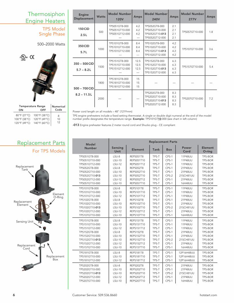
TPS ModelSingle Phase
500–2000 Watts
Thermosiphon Engine Heaters
For TPS Models
ReplacementCord
ReplacementBox
ReplacementTank
Sensing Unit
ElementO-Ring
ReplacementElement
Replacement Parts
EngineDisplacement
WattsModel Number
120VAmps
Model Number
240VAmps
Model Number
277VAmps
150 CID
2.5 L500
TPS051GT8-000TPS051GT10-000 TPS051GT12-000
—
4.24.24.2—
TPS052GT8-000 TPS052GT10-000TPS052GT10-013 TPS052GT12-000
2.12.12.12.1
TPS057GT10-000 1.8
350 CID
5.7 L1000
TPS101GT8-000 TPS101GT10-000 TPS101GT12-000
—
8.48.48.4—
TPS102GT8-000 TPS102GT10-000TPS102GT10-013TPS102GT12-000
4.24.24.24.2
TPS107GT10-000 3.6
350 – 500 CID
5.7 – 8.2 L1500
TPS151GT8-000 TPS151GT10-000 TPS151GT12-000
—
12.512.512.5—
TPS152GT8-000 TPS152GT10-000TPS152GT10-013 TPS152GT12-000
6.36.36.36.3
TPS157GT10-000 5.4
500 – 700 CID
8.2 – 11.5 L
1800TPS181GT8-000 TPS181GT10-000 TPS181GT12-000
151515
— — — —
2000 — —
TPS202GT8-000 TPS202GT10-000TPS202GT10-013 TPS202GT12-000
8.38.38.38.3
TPS207GT10-000 7.2
ModelNumber
Replacement Parts
Sensing Unit
Element Tank BoxPowerCord
Element O-ring
TPS051GT8-000TPS051GT10-000TPS051GT12-000TPS052GT8-000TPS052GT10-000TPS052GT10-013TPS052GT12-000TPS057GT10-000
LSU-8LSU-10LSU-12LSU-8LSU-10LSU-10LSU-12LSU-10
REPS051T8REPS051T10REPS051T12REPS052T8REPS052T10REPS052T10REPS052T12REPS057T10
TPS-TTPS-TTPS-TTPS-TTPS-TTPS-TTPS-TTPS-T
CPS-1CPS-1CPS-1CPS-1CPS-1CPS-2CPS-1CPS-1
11P48UU11P48UU11P48UU21P48UU21P48UU
21SCH81UU21P48UU16H48UU
TPS-BORTPS-BORTPS-BORTPS-BORTPS-BORTPS-BORTPS-BORTPS-BOR
TPS101GT8-000TPS101GT10-000TPS101GT12-000TPS102GT8-000TPS102GT10-000TPS102GT10-013TPS102GT12-000TPS107GT10-000
LSU-8LSU-10LSU-12LSU-8LSU-10LSU-10LSU-12LSU-10
REPS101T8REPS101T10REPS101T12REPS102T8REPS102T10REPS102T10REPS102T12REPS107T10
TPS-TTPS-TTPS-TTPS-TTPS-TTPS-TTPS-TTPS-T
CPS-1CPS-1CPS-1CPS-1CPS-1CPS-2CPS-1CPS-1
11P48UU11P48UU11P48UU21P48UU21P48UU
21SCH81UU21P48UU16H48UU
TPS-BORTPS-BORTPS-BORTPS-BORTPS-BORTPS-BORTPS-BORTPS-BOR
TPS151GT8-000TPS151GT10-000TPS151GT12-000TPS152GT8-000TPS152GT10-000TPS152GT10-013TPS152GT12-000TPS157GT10-000
LSU-8LSU-10LSU-12LSU-8LSU-10LSU-10LSU-12LSU-10
REPS151T8REPS151T10REPS151T12REPS152T8REPS152T10REPS152T10REPS152T12REPS157T10
TPS-TTPS-TTPS-TTPS-TTPS-TTPS-TTPS-TTPS-T
CPS-1CPS-1CPS-1CPS-1CPS-1CPS-2CPS-1CPS-1
11P48UU11P48UU11P48UU21P48UU21P48UU
21SCH81UU21P48UU16H48UU
TPS-BORTPS-BORTPS-BORTPS-BORTPS-BORTPS-BORTPS-BORTPS-BOR
TPS181GT8-000TPS181GT10-000TPS181GT12-000
LSU-8LSU-10LSU-12
REPS181T8REPS181T10REPS181T12
TPS-TTPS-TTPS-T
CPS-1CPS-1CPS-1
12P16H48UU12P16H48UU12P16H48UU
TPS-BORTPS-BORTPS-BOR
TPS202GT8-000TPS202GT10-000TPS202GT10-013TPS202GT12-000TPS207GT10-000
LSU-8LSU-10LSU-10LSU-12LSU-10
REPS202T8REPS202T10REPS202T10REPS202T12REPS207T10
TPS-TTPS-TTPS-TTPS-TTPS-T
CPS-1CPS-1CPS-2CPS-1CPS-1
21P48UU21P48UU
21SCH81UU21P48UU16H48UU
TPS-BORTPS-BORTPS-BORTPS-BORTPS-BOR
Temperature Range ON OFF
Numerical Code
80 °F (27 °C)100 °F (38 °C)120 °F (49 °C)
100 °F (38 °C)120 °F (49 °C)140 °F (60 °C)
81012
Power cord length on all models – 48” (1219 mm)
TPS engine preheaters include a fi xed setting thermostat. A single or double digit numeral at the end of the model number prefi x designates the temperature range. Example: TPS101GT10-000 (see chart in left column)
-013 Engine preheater features 2 meter round cord and Shucko plug - CE compliant

7Customer Service: 509.536.8660 hotstart.com
TPS Model w/in-line adjustable and remote thread-in fi xed thermostat.
Single Phase
500–2000 Watts
Thermosiphon Engine Heaters
In-LineAdjustableThermostat
Remote Thread-inFixed Temperature Thermostat
6.7”170mm7.9”
201mm
OUTLET HOSEBARB 0.625 I.D.
INLETHOSEBARB0.625 I.D.
ThermostatWell
Power Y-cord
AdjustableThermostatAssembly
4.25”108mm
4.6”117mm
1.5”38mm0.25” (4X) Holes
For MountingBrackets
Adjustable 90 ° – 130 °F (32 ° – 54 °C)On differential -20 °F (-7 °C)
In-line thermostat options:
EngineDisplacement
Model Number Volts Watts Phase AmpsThermostat Range
On Off
150 CID
2.5 L
TPS051GT12-001TPS051GT12-A00TPS052GT12-001TPS052GT12-A00
120120240240
500500500500
1111
4.24.22.12.1
100 °F (38 °C) 120 °F (49 °C) ADJUSTABLE 100 °F (38 °C) 120 °F (49 °C) ADJUSTABLE
350 CID
5.7 L
TPS101GT12-001TPS101GT12-A00TPS102GT12-001 TPS102GT12-A00
120120240240
1000100010001000
1111
8.48.44.24.2
100 °F (38 °C) 120 °F (49 °C) ADJUSTABLE 100 °F (38 °C) 120 °F (49 °C) ADJUSTABLE
350 – 500 CID
5.7 – 8.2 L
TPS151GT12-001TPS151GT12-A00TPS152GT12-001TPS152GT12-A00
120120240240
1500150015001500
1111
12.512.56.36.3
100 °F (38 °C) 120 °F (49 °C) ADJUSTABLE 100 °F (38 °C) 120 °F (49 °C) ADJUSTABLE
500 – 700 CID
8.2 – 11.5 L
TPS181GT12-001TPS181GT12-A00TPS202GT12-001TPS202GT12-A00
120120240240
1800180020002000
1111
15158.38.3
100 °F (38 °C) 120 °F (49 °C) ADJUSTABLE 100 °F (38 °C) 120 °F (49 °C) ADJUSTABLE
-001 Remote thread-in fi xed temperature thermostat
ModelNumber
Volts Watts
Replacement Parts
SensingUnit
ElementPowerY-cord
Thermostat Well
TPS051GT12-001TPS051GT12-A00 TPS052GT12-001TPS052GT12-A00
120120240240
500500500500
LSU-10RSU90-130LSU-10RSU90-130
REPS051T12REPS051T12REPS052T12REPS052T12
TPS-YC1#
TPS-YC2#
TW2374-1#
TW2374-1#
TPS101GT12-001TPS101GT12-A00TPS102GT12-001TPS102GT12-A00
120120240240
1000100010001000
LSU-10RSU90-130LSU-10RSU90-130
REPS101T12REPS101T12REPS102T12REPS102T12
TPS-YC1#
TPS-YC2#
TW2374-1#
TW2374-1#
TPS151GT12-001TPS151GT12-A00TPS152GT12-001TPS152GT12-A00
120120240240
1500150015001500
LSU-10RSU90-130LSU-10RSU90-130
REPS151T12REPS151T12REPS152T12REPS152T12
TPS-YC1#
TPS-YC2#
TW2374-1#
TW2374-1#
TPS181GT12-001TPS181GT12-A00TPS202GT12-001TPS202GT12-A00
120120240240
1800180020002000
LSU-10RSU90-130LSU-10RSU90-130
REPS181T12REPS181T12REPS202T12REPS202T12
12P16H54S54X10UU#
TPS-YC2#
TW2374-1#
TW2374-1#
-001 Remote thread-in fi xed temperature thermostat # Call Factory
For TPS Modelw/in-line adjustable and remote thread-in fi xed thermostat.
Single Phase
Common replacement parts for all TPS engine preheaters:— Tank— Box— Element O-ring
See table on page 6
Replacement Parts
Remote Adjustable Thermostat Assembly
Part Number TFTA-5/8HB

8 Customer Service: 509.536.8660 hotstart.com
CB ModelWeathertightSingle Phase
1500–2500 Watts
Thermosiphon Engine Heaters
CB Model without thermostat
CB Model with thermostat
EngineDisplacement
Model Number without Thermostat
Model Number with Thermostat
see chart 1Volts Watts Phase Amps
350 – 500 CID
5.7 – 8.2L
CB115100-000CB115800-000CB115200-000CB115700-000CB115300-000CB115400-000
CB1151XX-200CB1158XX-200CB1152XX-200CB1157XX-200CB1153XX-200CB1154XX-200
120208240277380480
150015001500150015001500
111111
12.57.26.35.43.93.1
500 – 600 CID
8.2 – 9.8L
CB120100-000CB120800-000CB120200-000CB120300-000CB120400-000
CB1201XX-200CB1208XX-200CB1202XX-200CB1203XX-200CB1204XX-200
120208240380480
20002000200020002000
11111
16.79.68.35.34.2
600 – 800 CID
9.8 – 13.1L
CB125100-000CB125800-000CB125200-000CB125700-000CB125300-000CB125400-000
CB1251XX-200CB1258XX-200CB1252XX-200CB1257XX-200CB1253XX-200CB1254XX-200
120208240277380480
250025002500250025002500
111111
20.812.010.49.06.65.2
Heaters with ThermostatsTo specify temperature range of thermostat, insert numerical code from chart in place of the XX in model number.
Example:Desired Temp. Range: 100 ° – 120 °FModel Number: CB1151XX-200Order as: CB115110-200
Temperature Range Numerical CodeON OFF
80 °F (27 °C)100 °F (38 °C)120 °F (49 °C)
100 °F (38 °C)120 °F (49 °C)140 °F (60 °C)
081012
Adjustable 90 ° – 130 °F(32 ° – 54 °C)
A3
CHART 1
16.2”411mm
4.1”104mm
5.75”146mm
OUTLET, 1” NPTFEMALE
INLET, 1” NPTFEMALE
4.3”109mm
20.1”510mm
OUTLET, 1” NPTFEMALE
5.1”129mm
5.2”132mm
5.75”146mm
INLET, 1” NPTFEMALE
CB Model
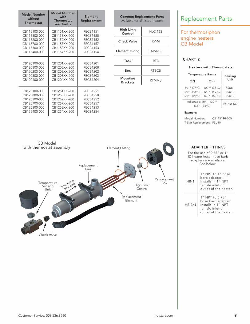
9Customer Service: 509.536.8660 hotstart.com
For thermosiphon engine heatersCB Model
Replacement Parts
Heaters with Thermostats
Temperature Range Sensing UnitON OFF
80 °F (27 °C)100 °F (38 °C)120 °F (49 °C)
100 °F (38 °C)120 °F (49 °C)140 °F (60 °C)
FSU8FSU10FSU12
Adjustable 90 ° – 130 °F(32 ° – 54 °C)
FSU90-130
Example:
Model Number: CB115110-200T-Stat Replacement: FSU10
Model Number without
Thermostat
Model Number with
Thermostatsee chart 2
Element Replacement
CB115100-000CB115800-000CB115200-000CB115700-000CB115300-000CB115400-000
CB1151XX-200CB1158XX-200CB1152XX-200CB1157XX-200CB1153XX-200CB1154XX-200
RECB1151RECB1158RECB1152RECB1157RECB1153RECB1154
CB120100-000CB120800-000CB120200-000CB120300-000CB120400-000
CB1201XX-200CB1208XX-200CB1202XX-200CB1203XX-200CB1204XX-200
RECB1201RECB1208RECB1202RECB1203RECB1204
CB125100-000CB125800-000CB125200-000CB125700-000CB125300-000CB125400-000
CB1251XX-200CB1258XX-200CB1252XX-200CB1257XX-200CB1253XX-200CB1254XX-200
RECB1251RECB1258RECB1252RECB1257RECB1253RECB1254
CHART 2
ReplacementBox
Element O-Ring
ReplacementElement
ReplacementTank
CB Modelwith thermostat assembly
High Limit Control
Temperature Sensing
Unit
Check Valve
Mounting
Brackets
ADAPTER FITTINGS
For the use of 0.75” or 1” ID heater hose, hose barb
adapters are available.See below.
HB-1
1” NPT to 1” hose barb adapter. Installs in 1” NPT female inlet or outlet of the heater.
HB-3/4
1” NPT to 0.75” hose barb adapter. Installs in 1” NPT female inlet or outlet of the heater.
Common Replacement Partsavailable for all listed heaters
High Limit Control
HLC-165
Check Valve RV-M
Element O-ring TMM-OR
Tank RTB
Box RTBCB
Mounting Brackets
RTMMB
6.2”157mm
23.5”597mm
OUTLET, 1” NPTFEMALE
INLET, 1” NPTFEMALE
5.8”147mm
ADJUSTABLE
10 Customer Service: 509.536.8660 hotstart.com
Thermosiphon Engine Heaters
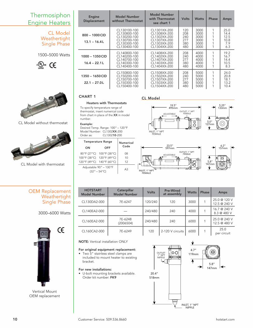
CL ModelWeathertightSingle Phase
1500–5000 Watts
CL Model without thermostat
CL Model with thermostat
Vertical Mount OEM replacement
EngineDisplacement
Model Number without Thermostat
Model Number with Thermostat
see chart 1Volts Watts Phase Amps
800 – 1000 CID
13.1 – 16.4 L
CL130100-100CL130800-100CL130200-100CL130700-100CL130300-100CL130400-100
CL1301XX-200CL1308XX-200CL1302XX-200CL1307XX-200CL1303XX-200CL1304XX-200
120208240277380480
300030003000300030003000
111111
25.014.412.510.87.96.3
1000 – 1350 CID
16.4 – 22.1 L
CL140800-100CL140200-100CL140700-100CL140300-100CL140400-100
CL1408XX-200CL1402XX-200CL1407XX-200CL1403XX-200CL1404XX-200
208240277380480
40004000400040004000
11111
19.216.714.410.58.3
1350 – 1650 CID
22.1 – 27.0 L
CL150800-100CL150200-100CL150700-100CL150300-100CL150400-100
CL1508XX-200CL1502XX-200CL1507XX-200CL1503XX-200CL1504XX-200
208240277380480
50005000500050005000
11111
24.020.818.113.210.4
Heaters with ThermostatsTo specify temperature range of thermostat, insert numerical code from chart in place of the XX in model number.
Example:Desired Temp. Range: 100 ° – 120 °FModel Number: CL1302XX-200Order as: CL130210-200
Temperature Range Numerical CodeON OFF
80 °F (27 °C)100 °F (38 °C)120 °F (49 °C)
100 °F (38 °C)120 °F (49 °C)140 °F (60 °C)
081012
Adjustable 90 ° – 130 °F(32 ° – 54 °C)
A3
19.5”495mm
OUTLET, 1” NPTFEMALE
5.25”133mm
ADJUSTABLE
INLET, 1” NPTFEMALE
5.0”127mm
CHART 1 CL Model
CL M
HOTSTARTModel Number
CaterpillarModel Number
Volts Pre-Wiredat assembly Watts Phase Amps
CL130DA2-000 7E-6247 120/240 120 3000 1 25.0 @ 120 V12.5 @ 240 V
CL140EA2-000 — 240/480 240 4000 1 16.7 @ 240 V8.3 @ 480 V
CL160EA2-000 7E-6248(2006504) 240/480 240 6000 1 25.0 @ 240 V
12.5 @ 480 V
CL160CA2-000 7E-6249 120 2-120 V circuits 6000 1 25.0 per circuit
20.4”518mm
OUTLET 1” NPTNIPPLE
4.7”119mm
INLET, 1” NPTNIPPLE
5.8”147mm
OEM ReplacementWeathertightSingle Phase
3000–6000 Watts
NOTE: Vertical installation ONLY
For original equipment replacement:• Two 5” stainless steel clamps are
included to mount heater to existing bracket.
For new installations:• U-bolt mounting brackets available.
Order kit number: FK9
11Customer Service: 509.536.8660 hotstart.com
Replacement Parts
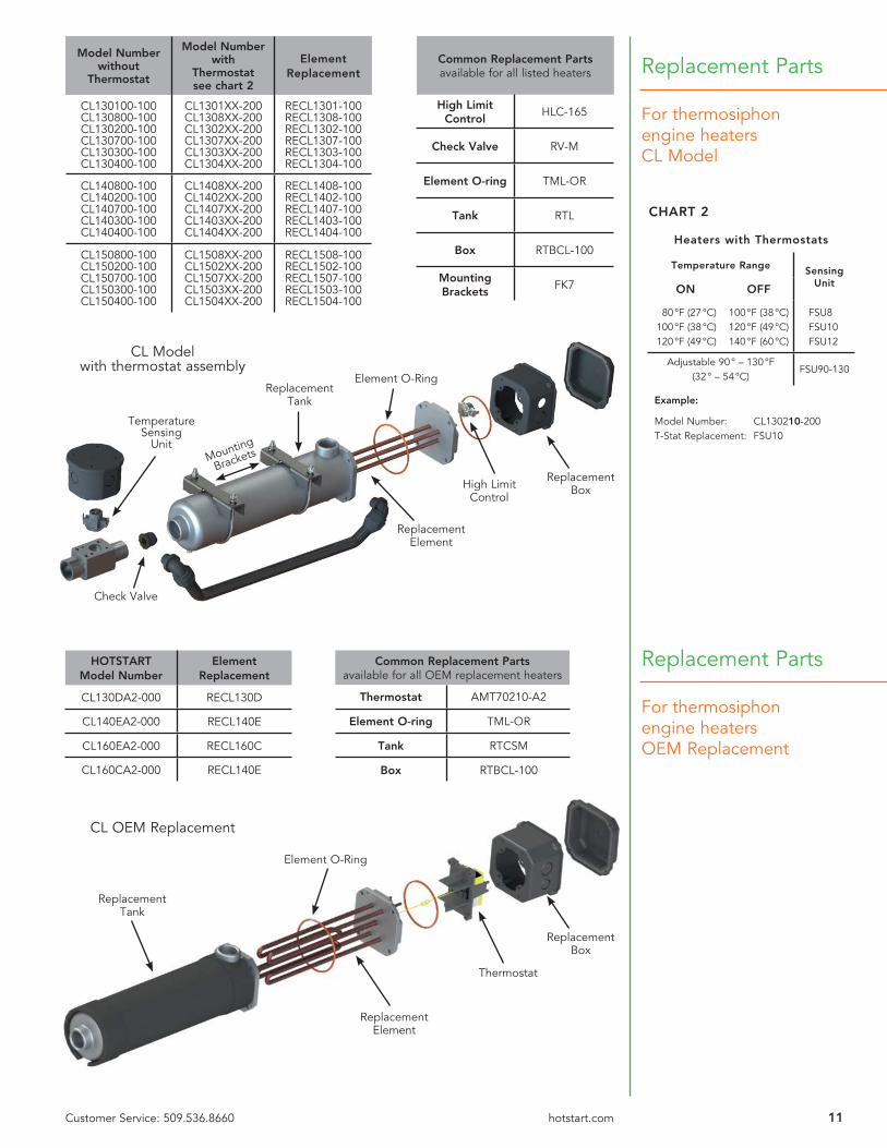
For thermosiphon engine heatersCL Model
Heaters with Thermostats
Temperature Range Sensing UnitON OFF
80 °F (27 °C)100 °F (38 °C)120 °F (49 °C)
100 °F (38 °C)120 °F (49 °C)140 °F (60 °C)
FSU8FSU10FSU12
Adjustable 90 ° – 130 °F(32 ° – 54 °C)
FSU90-130
Example:
Model Number: CL130210-200T-Stat Replacement: FSU10
CHART 2
ReplacementBox
Element O-Ring
ReplacementElement
ReplacementTank
CL Modelwith thermostat
CL Modelwith thermostat assembly
High Limit Control
Temperature Sensing
Unit
Check Valve
Mounting
Brackets
Model Number without
Thermostat
Model Number with
Thermostatsee chart 2
Element Replacement
CL130100-100CL130800-100CL130200-100CL130700-100CL130300-100CL130400-100
CL1301XX-200CL1308XX-200CL1302XX-200CL1307XX-200CL1303XX-200CL1304XX-200
RECL1301-100RECL1308-100RECL1302-100RECL1307-100RECL1303-100RECL1304-100
CL140800-100CL140200-100CL140700-100CL140300-100CL140400-100
CL1408XX-200CL1402XX-200CL1407XX-200CL1403XX-200CL1404XX-200
RECL1408-100RECL1402-100RECL1407-100RECL1403-100RECL1404-100
CL150800-100CL150200-100CL150700-100CL150300-100CL150400-100
CL1508XX-200CL1502XX-200CL1507XX-200CL1503XX-200CL1504XX-200
RECL1508-100RECL1502-100RECL1507-100RECL1503-100RECL1504-100
Common Replacement Partsavailable for all listed heaters
High Limit Control
HLC-165
Check Valve RV-M
Element O-ring TML-OR
Tank RTL
Box RTBCL-100
Mounting Brackets
FK7
HOTSTARTModel Number
Element Replacement
CL130DA2-000 RECL130D
CL140EA2-000 RECL140E
CL160EA2-000 RECL160C
CL160CA2-000 RECL140E
Common Replacement Partsavailable for all OEM replacement heaters
Thermostat AMT70210-A2
Element O-ring TML-OR
Tank RTCSM
Box RTBCL-100
Replacement Parts
For thermosiphon engine heatersOEM Replacement
ReplacementBox
Element O-Ring
ReplacementElement
ReplacementTank
CL OEM Replacement
Thermostat
12 Customer Service: 509.536.8660 hotstart.com
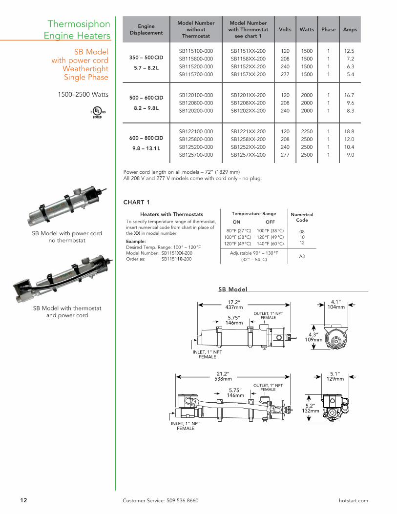
SB Modelwith power cord
WeathertightSingle Phase
1500–2500 Watts
Thermosiphon Engine Heaters
Power cord length on all models – 72” (1829 mm)All 208 V and 277 V models come with cord only - no plug.
SB Model with power cord no thermostat
SB Model with thermostat and power cord
EngineDisplacement
Model Number without
Thermostat
Model Number with Thermostat
see chart 1Volts Watts Phase Amps
350 – 500 CID
5.7 – 8.2 L
SB115100-000SB115800-000SB115200-000SB115700-000
SB1151XX-200SB1158XX-200SB1152XX-200SB1157XX-200
120208240277
1500150015001500
1111
12.57.26.35.4
500 – 600 CID
8.2 – 9.8 L
SB120100-000SB120800-000SB120200-000
SB1201XX-200SB1208XX-200SB1202XX-200
120208240
200020002000
111
16.79.68.3
600 – 800 CID
9.8 – 13.1 L
SB122100-000SB125800-000SB125200-000SB125700-000
SB1221XX-200SB1258XX-200SB1252XX-200SB1257XX-200
120208240277
2250250025002500
1111
18.812.010.49.0
4.3”109mm
4.1”104mm
17.2”437mm
INLET, 1” NPTFEMALE
OUTLET, 1” NPTFEMALE5.75”
146mm
SB Model
5.2”132mm
5.1”129mm
21.2”538mm
INLET, 1” NPTFEMALE
OUTLET, 1” NPTFEMALE5.75”
146mm
Heaters with ThermostatsTo specify temperature range of thermostat, insert numerical code from chart in place of the XX in model number.
Example:Desired Temp. Range: 100 ° – 120 °FModel Number: SB1151XX-200Order as: SB115110-200
Temperature Range Numerical CodeON OFF
80 °F (27 °C)100 °F (38 °C)120 °F (49 °C)
100 °F (38 °C)120 °F (49 °C)140 °F (60 °C)
081012
Adjustable 90 ° – 130 °F(32 ° – 54 °C)
A3
CHART 1
13Customer Service: 509.536.8660 hotstart.com
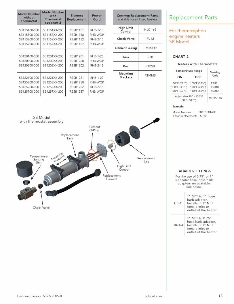
For thermosiphon engine heatersSB Model
Replacement PartsModel Number
without Thermostat
Model Number with
Thermostatsee chart 2
Element Replacement
Power Cord
SB115100-000SB115800-000SB115200-000SB115700-000
SB1151XX-200SB1158XX-200SB1152XX-200SB1157XX-200
RESB1151RESB1158RESB1152RESB1157
RHB-1-15RHB-WOPRHB-2-15RHB-WOP
SB120100-000SB120800-000SB120200-000
SB1201XX-200SB1208XX-200SB1202XX-200
RESB1201RESB1208RESB1202
RHB-1-20RHB-WOPRHB-2-15
SB122100-000SB125800-000SB125200-000SB125700-000
SB1221XX-200SB1258XX-200SB1252XX-200SB1257XX-200
RESB1221RESB1258RESB1252RESB1257
RHB-1-20RHB-WOPRHB-2-15RHB-WOP
ElementO-Ring
ReplacementTank
Check Valve
SB Modelwith thermostat assembly
ReplacementElement
ReplacementBox
High Limit Control
Temperature Sensing
Unit
Heaters with Thermostats
Temperature Range Sensing UnitON OFF
80 °F (27 °C)100 °F (38 °C)120 °F (49 °C)
100 °F (38 °C)120 °F (49 °C)140 °F (60 °C)
FSU8FSU10FSU12
Adjustable 90 ° - 130 °F(32 ° - 54 °C)
FSU90-130
Example:
Model Number: SB115110-200T-Stat Replacement: FSU10
CHART 2
Mounting
Brackets
ADAPTER FITTINGS
For the use of 0.75” or 1” ID heater hose, hose barb
adapters are available.See below.
HB-1
1” NPT to 1” hose barb adapter. Installs in 1” NPT female inlet or outlet of the heater.
HB-3/4
1” NPT to 0.75” hose barb adapter. Installs in 1” NPT female inlet or outlet of the heater.
Common Replacement Partsavailable for all listed heaters
High Limit Control
HLC-165
Check Valve RV-M
Element O-ring TMM-OR
Tank RTB
Box RTBSB
Mounting Brackets
RTMMB
14 Customer Service: 509.536.8660 hotstart.com
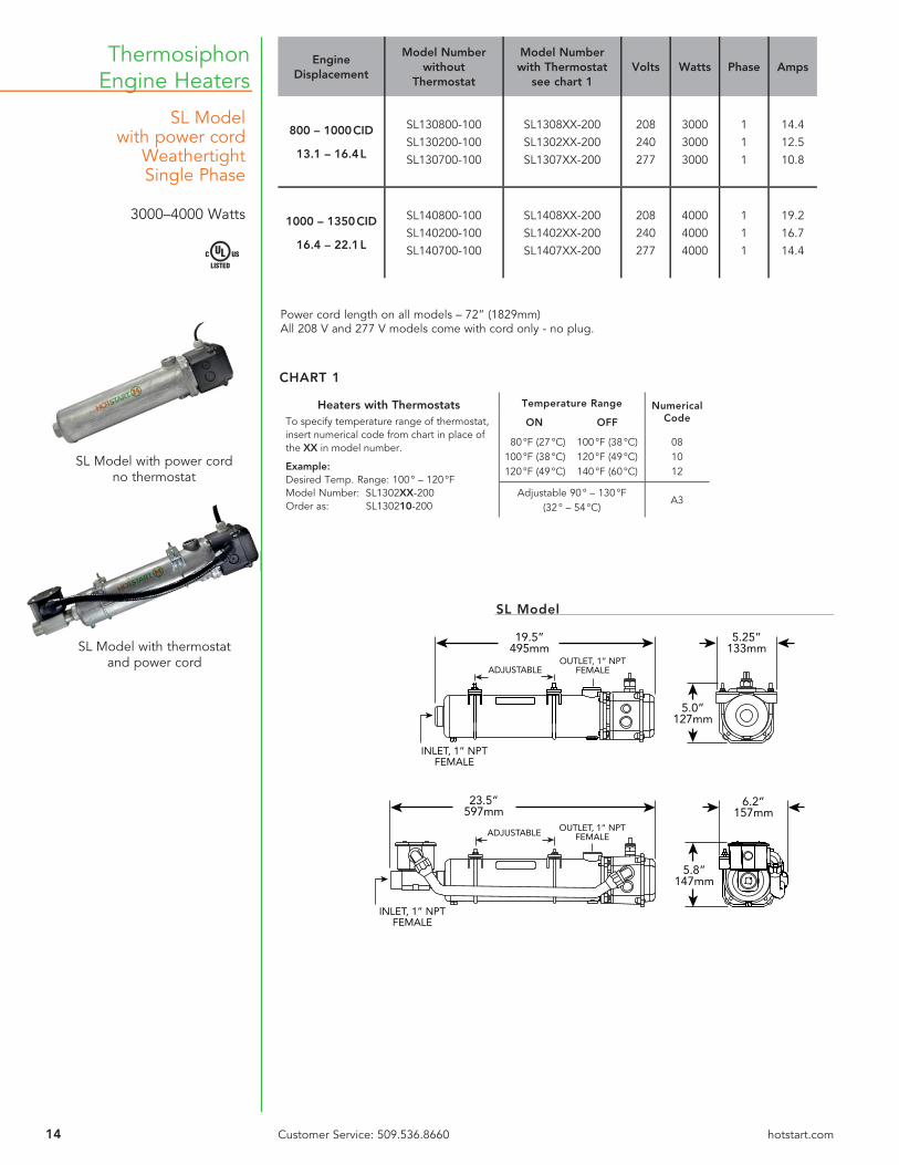
Thermosiphon Engine Heaters
SL Modelwith power cord
WeathertightSingle Phase
3000–4000 Watts
SL Model with power cord no thermostat
SL Model with thermostat and power cord
Power cord length on all models – 72” (1829mm)All 208 V and 277 V models come with cord only - no plug.
EngineDisplacement
Model Number without
Thermostat
Model Number with Thermostat
see chart 1Volts Watts Phase Amps
800 – 1000 CID
13.1 – 16.4 L
SL130800-100SL130200-100SL130700-100
SL1308XX-200SL1302XX-200SL1307XX-200
208240277
300030003000
111
14.412.510.8
1000 – 1350 CID
16.4 – 22.1 L
SL140800-100SL140200-100SL140700-100
SL1408XX-200SL1402XX-200SL1407XX-200
208240277
400040004000
111
19.216.714.4
SL Model
5.0”127mm
5.25”133mm
19.5”495mm
INLET, 1” NPTFEMALE
OUTLET, 1” NPTFEMALEADJUSTABLE
5.8”147mm
6.2”157mm
23.5”597mm
INLET, 1” NPTFEMALE
OUTLET, 1” NPTFEMALEADJUSTABLE
Heaters with ThermostatsTo specify temperature range of thermostat, insert numerical code from chart in place of the XX in model number.
Example:Desired Temp. Range: 100 ° – 120 °FModel Number: SL1302XX-200Order as: SL130210-200
Temperature Range Numerical CodeON OFF
80 °F (27 °C)100 °F (38 °C)120 °F (49 °C)
100 °F (38 °C)120 °F (49 °C)140 °F (60 °C)
081012
Adjustable 90 ° – 130 °F(32 ° – 54 °C)
A3
CHART 1

15Customer Service: 509.536.8660 hotstart.com
Replacement Parts
For thermosiphon engine heatersSL Model
Heaters with Thermostats
Temperature Range Sensing UnitON OFF
80 °F (27 °C)100 °F (38 °C)120 °F (49 °C)
100 °F (38 °C)120 °F (49 °C)140 °F (60 °C)
FSU8FSU10FSU12
Adjustable 90° – 130°F(32° – 54°C)
FSU90-130
Example:
Model Number: SL130210-200T-Stat Replacement: FSU10
CHART 2
ADAPTER FITTINGS
For the use of 0.75” or 1” ID heater hose, hose barb adapters
are available.See below.
HB-1
1” NPT to 1” hose barb adapter. Installs in 1” NPT female inlet or outlet of the heater.
HB-3/4
1” NPT to 0.75” hose barb adapter. Installs in 1” NPT female inlet or outlet of the heater.
Model Number without
Thermostat
Model Number with
Thermostatsee chart 2
Element Replacement
Power Cord
SL130800-100SL130200-100SL130700-100
SL1308XX-200SL1302XX-200SL1307XX-200
RESL1308-100RESL1302-100RESL1307-100
RHL-WOPRHL-2-15RHL-WOP
SL140800-100SL140200-100SL140700-100
SL1408XX-200SL1402XX-200SL1407XX-200
RESL1408-100RESL1402-100RESL1407-100
RHL-WOPRHL-2-20RHL-WOP
Common Replacement Partsavailable for all listed heaters
High Limit Control
HLC-165
Check Valve RV-M
Element O-ring TML-OR
Tank RTL
Box RTBCL-100
Mounting Brackets
FK7
ElementO-Ring
ReplacementTank
Check Valve
SL Modelwith thermostat assembly
ReplacementElement
ReplacementBox
High Limit Control
Temperature Sensing
Unit Mounting
Brackets

16 Customer Service: 509.536.8660 hotstart.com
WL SeriesWeathertightThree Phase
2500–5000 Watts
Thermosiphon Engine Heaters
WL Model without thermostat
WL Model with thermostat
Engine Displacement
Model Number without
Thermostat
Model Number with Thermostat
see chart 1Volts Watts Phase Amps
600 – 800 CID
9.8 – 13.1 L
WL325800-000WL325200-000WL325A00-000WL325400-000WL325500-000
WL3258XX-200WL3252XX-200WL325AXX-200WL3254XX-200WL3255XX-200
208240400480575
25002500250025002500
33333
6.96.03.63.02.5
1000 – 1350 CID
16.4 – 22.1 L
WL340800-000WL340200-000WL340A00-000WL340400-000WL340500-000
WL3408XX-200WL3402XX-200WL340AXX-200WL3404XX-200WL3405XX-200
208240400480575
40004000400040004000
33333
11.19.65.84.84.0
1350 – 1650 CID
22.1 – 27.0 L
WL350800-000WL350200-000WL350A00-000WL350400-000WL350500-000
WL3508XX-200WL3502XX-200WL350AXX-200WL3504XX-200WL3505XX-200
208240400480575
50005000500050005000
33333
13.912.07.26.05.0
W
5.0”127mm
5.25”133mm
19.5”495mm
INLET, 1” NPTFEMALE
OUTLET, 1” NPTFEMALEADJUSTABLE
5.8”147mm
6.2”157mm
23.5”597mm
INLET, 1” NPTFEMALE
OUTLET, 1” NPTFEMALEADJUSTABLE
WL Model
Heaters with ThermostatsTo specify temperature range of thermostat, insert numerical code from chart in place of the XX in model number.
Example:Desired Temp. Range: 100 ° – 120 °FModel Number: WL3252XX-200Order as: WL325210-200
Temperature Range Numerical CodeON OFF
80 °F (27 °C)100 °F (38 °C)120 °F (49 °C)
100 °F (38 °C)120 °F (49 °C)140 °F (60 °C)
081012
Adjustable 90 ° – 130 °F(32 ° – 54 °C)
A3
CHART 1
All 3 phase heaters with thermostat must use a control box. See Control Systems page 34.
17Customer Service: 509.536.8660 hotstart.com
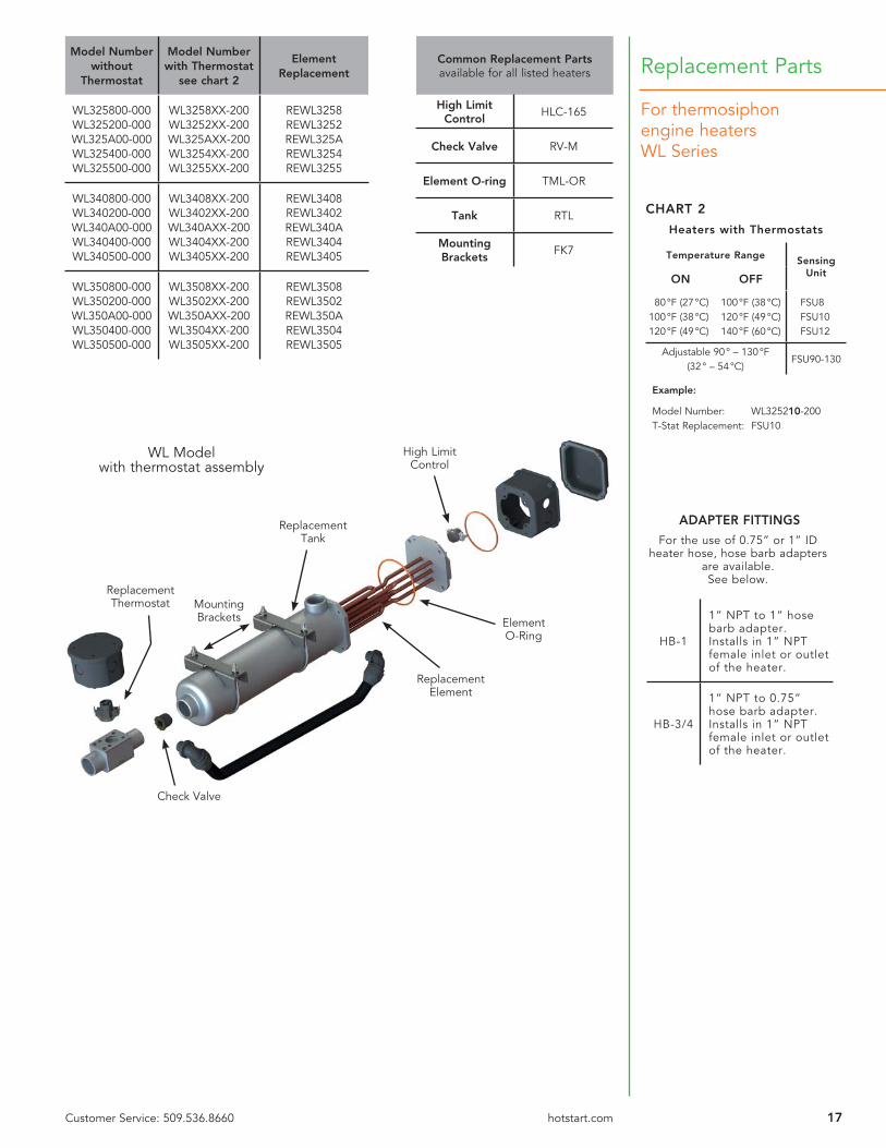
For thermosiphon engine heatersWL Series
Replacement PartsModel Number
without Thermostat
Model Number with Thermostat
see chart 2
ElementReplacement
WL325800-000WL325200-000WL325A00-000WL325400-000WL325500-000
WL3258XX-200WL3252XX-200WL325AXX-200WL3254XX-200WL3255XX-200
REWL3258REWL3252REWL325AREWL3254REWL3255
WL340800-000WL340200-000WL340A00-000WL340400-000WL340500-000
WL3408XX-200WL3402XX-200WL340AXX-200WL3404XX-200WL3405XX-200
REWL3408REWL3402REWL340AREWL3404REWL3405
WL350800-000WL350200-000WL350A00-000WL350400-000WL350500-000
WL3508XX-200WL3502XX-200WL350AXX-200WL3504XX-200WL3505XX-200
REWL3508REWL3502REWL350AREWL3504REWL3505
ReplacementTank
Mounting Brackets Element
O-Ring
ReplacementThermostat
Check Valve
ReplacementElement
WL Modelwith thermostat assembly
Heaters with Thermostats
Temperature Range Sensing UnitON OFF
80 °F (27 °C)100 °F (38 °C)120 °F (49 °C)
100 °F (38 °C)120 °F (49 °C)140 °F (60 °C)
FSU8FSU10FSU12
Adjustable 90 ° – 130 °F(32 ° – 54 °C)
FSU90-130
Example:
Model Number: WL325210-200T-Stat Replacement: FSU10
CHART 2
High Limit Control
ADAPTER FITTINGS
For the use of 0.75” or 1” ID heater hose, hose barb adapters
are available.See below.
HB-1
1” NPT to 1” hose barb adapter. Installs in 1” NPT female inlet or outlet of the heater.
HB-3/4
1” NPT to 0.75” hose barb adapter. Installs in 1” NPT female inlet or outlet of the heater.
Common Replacement Partsavailable for all listed heaters
High Limit Control
HLC-165
Check Valve RV-M
Element O-ring TML-OR
Tank RTL
Mounting Brackets
FK7

18 Customer Service: 509.536.8660 hotstart.com
EE Model Hazardous Location
Single Phase
1500-5000 Watts
Thermosiphon Engine Heaters
EE Model with thermostat
EE Model without thermostat
Engine Displacement
Model Number without Thermostat
Model Numberwith Thermostat
Volts Watts Phase Amp
500cidor less
8.2Lor less
EE115100-000EE115800-000EE115200-000
EE115110-000EE115810-000EE115210-000
120208240
150015001500
111
12.57.26.3
500 - 600cid
8.2 - 9.8L
EE120100-000EE120800-000EE120200-000
EE120110-000EE120810-000EE120210-000
120208240
200020002000
111
16.79.68.3
600 - 800cid
9.8 - 13.1L
EE125800-000EE125200-000EE125400-000
EE125810-000EE125210-000EE125410-000
208240480
250025002500
111
12.010.45.2
800 - 1000cid
13.1 - 16.4L
EE130800-000EE130200-000EE130400-000
EE130810-000EE130210-000EE130410-000
208240480
300030003000
111
14.412.56.3
1000 - 1350cid
16.4 - 22.1L
EE140800-000EE140200-000EE140400-000
EE140810-000EE140210-000EE140410-000
208240480
400040004000
111
19.216.78.3
1350 - 1650cid
22.1 - 27.0LEE150400-000 EE150410-000 480 5000 1 10.4
5.3”135mm
5.3”135mm
20.3”516mm
INLET, 1” NPTFEMALE
OUTLET, 1” NPTFEMALE
ADJUSTABLE
6.9”175mm
25.2”640mm OUTLET, 1” NPT
FEMALE
ADJUSTABLE
5.3”135mm
EE Model
All heaters over 480 V with a thermostat must use a control box. See Control Systems page 34.
Heaters with ThermostatsEE Models are only available with a fi xed setting temperature sensor.
Temperature Range Numerical Code
ON OFF
100 °F (38 °C) 120 °F (49 °C) 10

19Customer Service: 509.536.8660 hotstart.com
For thermosiphon engine heatersEE Model
Replacement PartsModel Number
withoutThermostat
Model Numberwith Thermostat
Element Replacement
EE115100-000EE115800-000EE115200-000EE115400-000
EE115110-000EE115810-000EE115210-000EE115410-000
REEE1151REEE1158REEE1152
E01541E-50NA-00
EE120100-000EE120800-000EE120200-000EE120400-000
EE120110-000EE120810-000EE120210-000EE120410-000
REEE1201REEE1208REEE1202
E02041E-50NA-00
EE125800-000EE125200-000EE125400-000
EE125810-000EE125210-000EE125410-000
REEE1258REEE1252
E02541E-C0NA-00
EE130800-000EE130200-000EE130400-000
EE130810-000EE130210-000EE130410-000
REEE1308REEE1302
E03041E-50NA-00
EE140800-000EE140200-000EE140400-000
EE140810-000EE140210-000EE140410-000
REEE1408REEE1402
E04041E-50NA-00
EE150400-000 EE150410-000 E05041E-C0NA-00
ReplacementTank
Mounting
Brackets
Flange &O-Ring
ReplacementThermostat
Check Valve
ReplacementElement
MC-HL Cable
EE Modelwith thermostat assembly
Heaters with Thermostats
Temperature Range Sensing Unit
ON OFF
100 °F (38 °C) 120 °F (49 °C) RSU10
Example:
Model Number: EE130210-000T-Stat Replacement: RSU10
ADAPTER FITTINGS
For the use of 0.75” or 1” ID heater hose, hose barb adapters
are available.See below.
HB-1
1” NPT to 1” hose barb adapter. Installs in 1” NPT female inlet or outlet of the heater.
HB-3/4
1” NPT to 0.75” hose barb adapter. Installs in 1” NPT female inlet or outlet of the heater.
Common Replacement Partsavailable for all listed heaters
Check Valve RV-M
Flange RF-L
Flange O-ring TML-OR
Tank RTL
MC-HL cable PRP104301-029
Mounting Brackets
FK7

20 Customer Service: 509.536.8660 hotstart.com
EE ModelHazardous Location
Three Phase
1500-5000 Watts
Thermosiphon Engine Heaters
Engine Displacement
Model Number without Thermostat
Model Number with Thermostat
Volts Watts Phase Amp
500cidor less
8.2Lor less
EE315800-000EE315200-000EE315400-000
EE315810-000EE315210-000EE315410-000
208240480
150015001500
333
4.23.61.8
500 - 600cid
8.2 - 9.8L
EE320800-000EE320200-000EE320400-000
EE320810-000EE320210-000EE320410-000
208240480
200020002000
333
5.64.82.4
600 - 800cid
9.8 - 13.1L
EE325800-000EE325200-000EE325400-000
EE325810-000EE325210-000EE325410-000
208240480
250025002500
333
6.96.03.0
800 - 1000cid
13.1 - 16.4L
EE330800-000EE330200-000EE330400-000
EE330810-000EE330210-000EE330410-000
208240480
300030003000
333
8.37.23.6
1000 - 1350cid
16.4 - 22.1L
EE340800-000EE340200-000EE340400-000
EE340810-000EE340210-000EE340410-000
208240480
400040004000
333
11.19.64.8
1350 - 1650cid
22.1 - 27.0L
EE350800-000EE350200-000EE350400-000
EE350810-000EE350210-000EE350410-000
208240480
500050005000
333
13.912.06.0
EE Model with thermostat
EE Model without thermostat
E
All 3 phase heaters with thermostat must use a control box. See Control Systems page 34.
Heaters with ThermostatsEE Models are only available with a fi xed setting temperature sensor.
Temperature Range Numerical Code
ON OFF
100 °F (38 °C) 120 °F (49 °C) 10
5.3”135mm
5.3”135mm
20.3”516mm
INLET, 1” NPTFEMALE
OUTLET, 1” NPTFEMALE
ADJUSTABLE
6.9”175mm
25.2”640mm OUTLET, 1” NPT
FEMALE
ADJUSTABLE
5.3”135mm
EE Model

21Customer Service: 509.536.8660 hotstart.com
For thermosiphon engine heatersEE Model
Replacement PartsModel Number
without Thermostat
Model Number with Thermostat
Element Replacement
EE315800-000EE315200-000EE315400-000
EE315810-000EE315210-000EE315410-000
E01583E-15NA-00E01523E-15NA-00E01543E-15NA-00
EE320800-000EE320200-000EE320400-000
EE320810-000EE320210-000EE320410-000
E02083E-25NA-00E02023E-25NA-00E02043E-25NA-00
EE325800-000EE325200-000EE325400-000
EE325810-000EE325210-000EE325410-000
E02583E-30NA-00E02523E-30NA-00E02543E-30NA-00
EE330800-000EE330200-000EE330400-000
EE330810-000EE330210-000EE330410-000
E03083E-30NA-00E03023E-30NA-00E03043E-30NA-00
EE340800-000EE340200-000EE340400-000
EE340810-000EE340210-000EE340410-000
E04083E-50NA-00E04023E-50NA-00E04043E-50NA-00
EE350800-000EE350200-000EE350400-000
EE350810-000EE350210-000EE350410-000
E05083E-50NA-00E05023E-50NA-00E05043E-50NA-00
ADAPTER FITTINGS
For the use of 0.75” or 1” ID heater hose, hose barb adapters
are available.See below.
HB-1
1” NPT to 1” hose barb adapter. Installs in 1” NPT female inlet or outlet of the heater.
HB-3/4
1” NPT to 0.75” hose barb adapter. Installs in 1” NPT female inlet or outlet of the heater.
Heaters with Thermostats
Temperature Range Sensing Unit
ON OFF
100 °F (38 °C) 120 °F (49 °C) RSU10
Example:
Model Number: EE330210-000T-Stat Replacement: RSU10
Common Replacement Partsavailable for all listed heaters
Check Valve RV-M
Flange RF-L
Flange O-ring TML-OR
Tank RTL
MC-HL cable PRP104301-029
Mounting Brackets
FK7
ReplacementTank
Mounting
Brackets
Flange &O-Ring
ReplacementThermostat
Check Valve
ReplacementElement
MC-HL Cable
EE Modelwith thermostat assembly

Installation Instructions for Thermosiphon Engine Heaters
22 Customer Service: 509.536.8660 hotstart.com
The HOTSTART engine heater uses thermosiphon action – the natural expansion and rising action of a heated fl uid – to circulate heated coolant throughout an engine’s water jacket. Installation of the heating system is critical. Please refer to specifi c instructions that accompany your HOTSTART engine heater or visit hotstart.com and select Installation Instructions, Manuals and Guides from the Resources tab.
For “V” engines larger than eight cylinders or over 1000 CID (15L), HOTSTART recommends using a HOTfl ow® heater. Please refer to pages 4-5 for heater selection.
Prior to heater installation, inspect the coolant supply. When mixing coolant, only use deionized or distilled water and low-silicate antifreeze. Refer to your engine’s manufacturer recommendations. Do not exceed 60% antifreeze to 40% water ratio. Never add unmixed water and antifreeze to an engine. Do not add anti-leak or other coolant additives.
RETURN PORT• Select a return port away from the engine thermostat.• Select a return port high on the engine.• Select a return port toward the rear of the engine.• Select a return port away from the remote thermostat.
NOTE: If an optional remote thermostat is installed• Select a return port away from the supply port.
SUPPLY PORT• Select a supply port low on the engine.• Select a supply port toward the front of
the engine.• Select a supply port away from the
return port.
HEATER MOUNTING• Mount the heater in the proper orientation. Ensure
heater outlet faces upward.• Mount the heater to a vibration-isolated surface.• Mount the heater directly below the return port.• Mount the heater at least 6 inches (15 cm) below the
lowest point of the water jacket.
PREPARING• Drain and fl ush cooling system to remove any debris present in the
engine’s cooling system.
• Select return port. The return port will allow heated coolant to return to the engine.
• Select supply port. The supply port will allow coolant to fl ow from the engine to the heater.
• Select fi ttings. Use the following table to determine the proper port fi tting size for your heater:
• Select hoses. Use the following table to determine the minimum hose inner diameter for your heater:
HOTSTART recommends installing valves to isolate the heating system in case of service. To minimize fl ow restriction, select full-fl ow ball isolation valves.
MOUNTING• Select a heater mounting position directly below the return port
and at least 6 inches (15 cm) below the lowest point of the engine’s water jacket. Mount heater using the supplied mounting brackets and fasteners.
PLUMBING• Install isolation valves to port fi ttings.
• Route and install return hose. The return hose should continuously rise from the heater to the return port.
• Route and install supply hose. The supply hose should continuously descend from the supply port to the heater.
• Refi ll cooling system with coolant. To prevent air pockets, refi ll coolant with return hose removed.
• Start engine. Allow engine to run until engine thermostat opens, purging air from cooling system. Engine must be run to eliminate air from heating system before energizing heater.
WIRING• Connect heater to an appropriately rated power source. Ensure
power source is grounded and in accordance with local and national electrical codes. If necessary, install control box:
If your heater is single-phase and rated up to 480 volts, your heater may be powered directly without the use of a control relay or contactor.
If your heater is three-phase or is single-phase and rated for over 480 volts, the heater thermostats must be used in a control circuit with a contactor for switching the main power to the heating elements.
CB/CL/SB/SL 500–3000 watts 1/2 inch NPT
CB/CL/SB/SL 3750–5000 watts 3/4 inch NPT
WL/EE 1500–5000 watts 3/4 inch NPT
CB/CL/SB/SL 500–3000 watts 3/4 inch
CB/CL/SB/SL 3750–5000 watts 1 inch
WL/EE 1500–5000 watts 1 inch
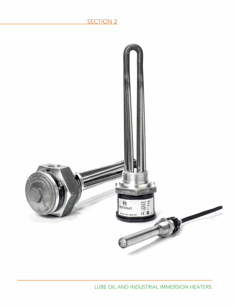
SECTION 2
LUBE OIL AND INDUSTRIAL IMMERSION HEATERS

24 Customer Service: 509.536.8660 hotstart.com
Oil Heaters
Weathertight models are furnished with a 4’ (1.2m) oil- and heat-resistant power cord without plug. Hazardous Location models are furnished with 18” (457mm) of lead wire for connection to the power leads in an approved splice box.
OilCapacity
WeathertightHeater Only
Weathertight With Thermostat
Hazardous Location
Heater OnlyVolts Watts Amps
Watts/Sq Inch
3/8” N.P.T. THREAD WITH A 2 1/8” (54mm) PROBE LENGTH
2 qt. (2L)or Less
OW005100-000OW005200-000
——
——
120240
5050
.4
.220.020.0
1/2” N.P.T. THREAD WITH A 4” (101mm) PROBE LENGTH
2 - 6 qt.2 - 5.7L
OW212100-000OW212200-000
OW2121XX-000OW2122XX-000
OE212100-000OE212200-000
120240
125125
1.0.5
24.624.6
3/4” N.P.T. THREAD WITH A 5” (127mm) PROBE LENGTH
1 - 5 gal.3.8 - 19L
OW415100-000OW415200-000
OW4151XX-000OW4152XX-000
OE415100-000OE415200-000
120240
150150
1.3.6
14.6*14.6*
5 - 15 gal.19 - 57L
OW430100-000OW430800-000OW430200-000
OW4301XX-000OW4308XX-000OW4302XX-000
OE430100-000OE430800-000OE430200-000
120208240
300225300
2.61.11.2
29.322.029.3
1” N.P.T. THREAD WITH A 5 1/4” (133mm) PROBE LENGTH
1 - 5 gal.3.8 - 19L
OW615100-000OW615200-000
OW6151XX-000OW6152XX-000
OE615100-000OE615200-000
120240
150150
1.3.6
10.7*10.7*
5 - 15 gal.19 - 57L
OW630100-000OW630800-000OW630200-000
———
OW6301XX-000OW6308XX-000OW6302XX-000
———
OE630100-000OE630800-000OE630200-000OE630700-000OE630300-000OE630400-000
120208240277380480
300375300265300300
2.61.81.21.01.0.6
21.428.021.419.021.421.4
15 - 30 gal.57 - 113L
OW650100-000OW650800-000OW650200-000OW650700-000
———
OW6501XX-000OW6508XX-000OW6502XX-000OW6507XX-000
———
OE650100-000OE650800-000OE650200-000OE650700-000OE650300-000OE650400-000OE650500-000
120208240277380480575
500450500400500500500
4.12.22.01.41.31.00.8
35.733.035.730.035.735.735.7
Oil Capacity Volts Watts
1/2” NPT with 4” (101mm)
Probe Length
3/4” NPT with 4 7/8” (124mm) Probe Length
1” NPT with 5 3/8” (136mm) Probe Length
AmpsWatts Per
SquareInch
2 qt. 2.0L
or Less
1224
7575
OW207900-012—
OW407900-012OW407900-024
——
6.33.1
1/2” — 14.7* WSI3/4” — 7.3* WSI
2-6 qt.2.0-2.7L
24 125 OW212900-024 — — 5.2 24.6 WSI
1-5 gal.3.8-19L
1224
150150
——
OW415900-012OW415900-024
OW615900-012OW615900-024
12.56.3
3/4” — 14.6* WSI1” — 10.7* WSI
5-15 gal.19-57L
1224
300300
——
—OW430900-024
OW630900-012OW630900-024
25.012.5
3/4”— 29.3 WSI1” — 21.4 WSI
15-30 gal.57-113L
24 500 — — OW650900-024 20.8 35.7 WSI
*NOTE: If heating gear oil (medium weight viscosity), HOTSTART recommends using low watt density heaters.
To specify temperature range of thermostat, insert code from chart in place of the XX in model number.
Example:
Desired Temp. Range 80 °–100 °FModel Number: OW2121XX-000Order as: OW212108-000
Temperature RangeCode
ON OFF
60 °F (16 °C)
80 °F (27 °C)
100 °F (38 °C)
80 °F (27 °C)
100 °F (38 °C)
120 °F (49 °C)
06
08
10
See p.25 for remote thermostat assembly part numbers.
12 V DC and 24 V DC oil heaters can be powered directly from the battery, but will drain the battery very rapidly unless charged by an alternator or generator.
DC Oil Heaters12 V and 24 V
_
+
12 or 24V DC
DIT COIL
C1
C1
MagneticContactors
Oil Heater
C1
When used with a thermostat control, all DC oil heaters must use a DC relay.
12 Vdc/24 Vdc CONTROL BOXES
25 AmpsMaximum
12V24V
JBMC330DC-12VJBMC330DC-24V
Oil heater with Y-cord and remote thermostat
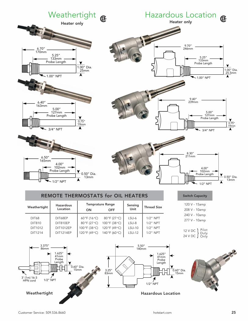
Use a thermostat with all lube oil heaters to protect the oil from overheating. Lube oil heaters must always be installed in the sump with the entire heater submerged below the oil level at all times. See page 25 for remote thermostat part numbers.
Oil Heaters up to 277 V AC meet recognized CSA standards for
safety or performance.
25Customer Service: 509.536.8660 hotstart.com
Heater only
Hazardous LocationWeathertightHeater only
0.50” Dia.13mm
8.30”211mm
4.00”102mm
Probe Length
1/2” NPT
0.75”19mm
9.40”239mm
5.00”127mm
Probe Length
3/4” NPT
9.70”246mm
5.25”133mm
Probe Length
1.00” NPT
1.00” Dia.25.5mm
0.50” Dia.13mm
6.50”165mm
4.00”102mm
Probe Length
1/2” NPT
1.00” Dia.25mm
6.70”170mm
5.25”133mm
Probe Length
1.00” NPT
0.75”19mm
6.40”163mm
5.00”127mm
Probe Length
3/4” NPT
REMOTE THERMOSTATS for OIL HEATERS
Weathertight Hazardous Location
Temprature Range
ON OFFSensing
UnitThread Size
DIT68DIT810DIT1012DIT1214
DIT68EPDIT810EPDIT1012EPDIT1214EP
60 °F (16 °C) 80 °F (27 °C) 80 °F (27 °C) 100 °F (38 °C) 100 °F (38 °C) 120 °F (49 °C) 120 °F (49 °C) 140 °F (60 °C)
LSU-6LSU-8LSU-10LSU-12
1/2” NPT1/2” NPT1/2” NPT1/2” NPT
Switch Capacity
120 V - 15amp
208 V - 10amp
240 V - 10amp
277 V - 10amp
12 V DC
24 V DC
Pilot Duty Only}
5.50”140mm
1.625”41mmProbeLength
1/2” NPT
0.60” Dia.15mm
3.25”83mm
Weathertight Hazardous Location
3.375”86mm
1.625”41mmProbeLength
1/2” NPT
0.60” Dia.15mm
3’ (1m) 16-3HPN cord
26 Customer Service: 509.536.8660 hotstart.com
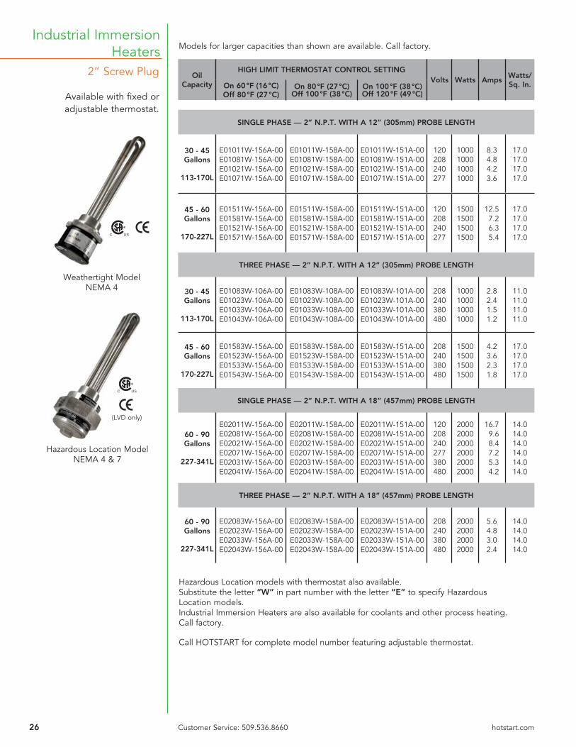
2” Screw Plug
Available with fi xed or adjustable thermostat.
Industrial Immersion Heaters
Weathertight ModelNEMA 4
C US
Hazardous Location ModelNEMA 4 & 7
Hazardous Location models with thermostat also available. Substitute the letter “W” in part number with the letter “E” to specify Hazardous Location models.Industrial Immersion Heaters are also available for coolants and other process heating. Call factory.
Call HOTSTART for complete model number featuring adjustable thermostat.
Models for larger capacities than shown are available. Call factory.
Oil Capacity
HIGH LIMIT THERMOSTAT CONTROL SETTINGVolts Watts Amps
Watts/ Sq. In.On 60 °F (16 °C)
Off 80 °F (27 °C)On 80 °F (27 °C)
Off 100 °F (38 °C)On 100 °F (38 °C)Off 120 °F (49 °C)
SINGLE PHASE — 2” N.P.T. WITH A 12” (305mm) PROBE LENGTH
30 - 45 Gallons
113-170L
E01011W-156A-00E01081W-156A-00E01021W-156A-00E01071W-156A-00
E01011W-158A-00E01081W-158A-00E01021W-158A-00E01071W-158A-00
E01011W-151A-00E01081W-151A-00E01021W-151A-00E01071W-151A-00
120208240277
1000100010001000
8.34.84.23.6
17.017.017.017.0
45 - 60 Gallons
170-227L
E01511W-156A-00E01581W-156A-00E01521W-156A-00E01571W-156A-00
E01511W-158A-00E01581W-158A-00E01521W-158A-00E01571W-158A-00
E01511W-151A-00E01581W-151A-00E01521W-151A-00E01571W-151A-00
120208240277
1500150015001500
12.57.26.35.4
17.017.017.017.0
THREE PHASE — 2” N.P.T. WITH A 12” (305mm) PROBE LENGTH
30 - 45 Gallons
113-170L
E01083W-106A-00E01023W-106A-00E01033W-106A-00E01043W-106A-00
E01083W-108A-00E01023W-108A-00E01033W-108A-00E01043W-108A-00
E01083W-101A-00E01023W-101A-00E01033W-101A-00E01043W-101A-00
208240380480
1000100010001000
2.82.41.51.2
11.011.011.011.0
45 - 60 Gallons
170-227L
E01583W-156A-00E01523W-156A-00E01533W-156A-00E01543W-156A-00
E01583W-158A-00E01523W-158A-00E01533W-158A-00E01543W-158A-00
E01583W-151A-00E01523W-151A-00E01533W-151A-00E01543W-151A-00
208240380480
1500150015001500
4.23.62.31.8
17.017.017.017.0
SINGLE PHASE — 2” N.P.T. WITH A 18” (457mm) PROBE LENGTH
60 - 90 Gallons
227-341L
E02011W-156A-00E02081W-156A-00E02021W-156A-00E02071W-156A-00E02031W-156A-00E02041W-156A-00
E02011W-158A-00E02081W-158A-00E02021W-158A-00E02071W-158A-00E02031W-158A-00E02041W-158A-00
E02011W-151A-00E02081W-151A-00E02021W-151A-00E02071W-151A-00E02031W-151A-00E02041W-151A-00
120208240277380480
200020002000200020002000
16.79.68.47.25.34.2
14.014.014.014.014.014.0
THREE PHASE — 2” N.P.T. WITH A 18” (457mm) PROBE LENGTH
60 - 90 Gallons
227-341L
E02083W-156A-00E02023W-156A-00E02033W-156A-00E02043W-156A-00
E02083W-158A-00E02023W-158A-00E02033W-158A-00E02043W-158A-00
E02083W-151A-00E02023W-151A-00E02033W-151A-00E02043W-151A-00
208240380480
2000200020002000
5.64.83.02.4
14.014.014.014.0
C US
(LVD only)

27Customer Service: 509.536.8660 hotstart.com
2” Screw Plug
Industrial Immersion Heaters
Fixed Thermostat Assembly
HOTSTART immersion heaters include a fi xed-setting, built-in thermostat and are available with an adjustable thermostat.
12” or 18”305mm or 457mm
4.3”109mm
12” or 18”305mm or 457mm
5.5”140mm
3.6”91mm
4.4”112mm
Adjustable Thermostat Assembly
TEMPERATURE RANGE CONTROL
OFF 70 °– 210 °F(21 °– 99 °C) AMT70-210
Nominal thermal differential is 8 °F (-13 °C)
ELECTRICAL RATING
30 Amps at 125 Vac30 Amps at 240 Vac30 Amps at 277 Vac20 Amps at 480 Vac
TEMPERATURE RANGE ON OFF
CONTROL
60 °F (16 °C)80 °F (27 °C)
100 °F (38 °C)
80 °F (27 °C)100 °F (38 °C)120 °F (49 °C)
HLC-6HLC-8HLC-10
ELECTRICAL RATING
15 Amps at 120 Vac10 Amps at 240 Vac10 Amps at 277 Vac
AdjustableThermostat
ControlThermostat
SensorControl
NOTES: On applications where level of fl uid is subject to change, a liquid level switch mounted a minimum of 3–4” (76–102mm) above element is recommended. Liquid level switch is not included with heater.
All 380 V and 480 V heaters must be used in conjunction with contactor and control transformer.
All three phase models must be used with a contactor. See page 34.
Higher or lower temperature ranges are available. Consult HOTSTART.
Weathertight ModelNEMA 4
Hazardous Location ModelNEMA 4 & 7
28 Customer Service: 509.536.8660 hotstart.com
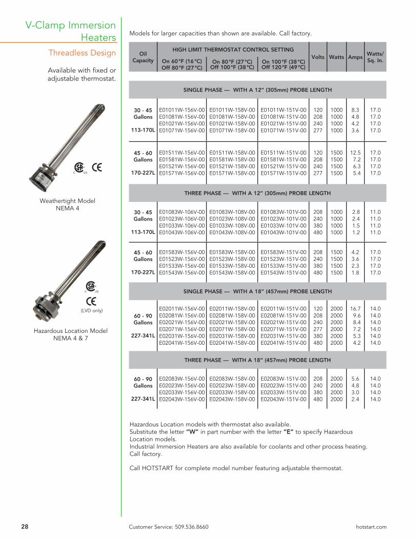
Threadless Design
Available with fi xed or adjustable thermostat.
V-Clamp Immersion Heaters
Hazardous Location models with thermostat also available. Substitute the letter “W” in part number with the letter “E” to specify Hazardous Location models.Industrial Immersion Heaters are also available for coolants and other process heating. Call factory.
Call HOTSTART for complete model number featuring adjustable thermostat.
Oil Capacity
HIGH LIMIT THERMOSTAT CONTROL SETTINGVolts Watts Amps
Watts/ Sq. In.On 60 °F (16 °C)
Off 80 °F (27 °C)On 80 °F (27 °C)
Off 100 °F (38 °C)On 100 °F (38 °C)Off 120 °F (49 °C)
SINGLE PHASE — WITH A 12” (305mm) PROBE LENGTH
30 - 45 Gallons
113-170L
E01011W-156V-00E01081W-156V-00E01021W-156V-00E01071W-156V-00
E01011W-158V-00E01081W-158V-00E01021W-158V-00E01071W-158V-00
E01011W-151V-00E01081W-151V-00E01021W-151V-00E01071W-151V-00
120208240277
1000100010001000
8.34.84.23.6
17.017.017.017.0
45 - 60 Gallons
170-227L
E01511W-156V-00E01581W-156V-00E01521W-156V-00E01571W-156V-00
E01511W-158V-00E01581W-158V-00E01521W-158V-00E01571W-158V-00
E01511W-151V-00E01581W-151V-00E01521W-151V-00E01571W-151V-00
120208240277
1500150015001500
12.57.26.35.4
17.017.017.017.0
THREE PHASE — WITH A 12” (305mm) PROBE LENGTH
30 - 45 Gallons
113-170L
E01083W-106V-00E01023W-106V-00E01033W-106V-00E01043W-106V-00
E01083W-108V-00E01023W-108V-00E01033W-108V-00E01043W-108V-00
E01083W-101V-00E01023W-101V-00E01033W-101V-00E01043W-101V-00
208240380480
1000100010001000
2.82.41.51.2
11.011.011.011.0
45 - 60 Gallons
170-227L
E01583W-156V-00E01523W-156V-00E01533W-156V-00E01543W-156V-00
E01583W-158V-00E01523W-158V-00E01533W-158V-00E01543W-158V-00
E01583W-151V-00E01523W-151V-00E01533W-151V-00E01543W-151V-00
208240380480
1500150015001500
4.23.62.31.8
17.017.017.017.0
SINGLE PHASE — WITH A 18” (457mm) PROBE LENGTH
60 - 90 Gallons
227-341L
E02011W-156V-00E02081W-156V-00E02021W-156V-00E02071W-156V-00E02031W-156V-00E02041W-156V-00
E02011W-158V-00E02081W-158V-00E02021W-158V-00E02071W-158V-00E02031W-158V-00E02041W-158V-00
E02011W-151V-00E02081W-151V-00E02021W-151V-00E02071W-151V-00E02031W-151V-00E02041W-151V-00
120208240277380480
200020002000200020002000
16.79.68.47.25.34.2
14.014.014.014.014.014.0
THREE PHASE — WITH A 18” (457mm) PROBE LENGTH
60 - 90 Gallons
227-341L
E02083W-156V-00E02023W-156V-00E02033W-156V-00E02043W-156V-00
E02083W-158V-00E02023W-158V-00E02033W-158V-00E02043W-158V-00
E02083W-151V-00E02023W-151V-00E02033W-151V-00E02043W-151V-00
208240380480
2000200020002000
5.64.83.02.4
14.014.014.014.0
Models for larger capacities than shown are available. Call factory.
Weathertight ModelNEMA 4
Hazardous Location ModelNEMA 4 & 7
C US
C US
(LVD only)
29Customer Service: 509.536.8660 hotstart.com
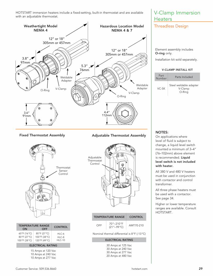
Threadless Design
V-Clamp Immersion Heaters
Element assembly includes O-ring only.
Installation kit sold separately.
NOTES: On applications where level of fl uid is subject to change, a liquid level switch mounted a minimum of 3–4” (76–102mm) above element is recommended. Liquid level switch is not included with heater.
All 380 V and 480 V heaters must be used in conjunction with contactor and control transformer.
All three phase heaters must be used with a contactor. See page 34.
Higher or lower temperature ranges are available. Consult HOTSTART.
12” or 18”305mm or 457mm
3.8”97mm
12” or 18”305mm or 457mm
5.3”76mm
3.6”91mm
4.4”112mm
Weathertight ModelNEMA 4
Hazardous Location ModelNEMA 4 & 7
V-ClampWeldable Adapter
O-RingV-Clamp
O-Ring
Weldable Adapter
HOTSTART immersion heaters include a fi xed-setting, built-in thermostat and are available with an adjustable thermostat.
Fixed Thermostat Assembly Adjustable Thermostat Assembly
TEMPERATURE RANGE CONTROL
OFF 70 °– 210 °F(21 °– 99 °C) AMT70-210
Nominal thermal differential is 8 °F (-13 °C)
ELECTRICAL RATING
30 Amps at 125 Vac30 Amps at 240 Vac30 Amps at 277 Vac20 Amps at 480 Vac
TEMPERATURE RANGE ON OFF
CONTROL
60 °F (16 °C)80 °F (27 °C)
100 °F (38 °C)
80 °F (27 °C)100 °F (38 °C)120 °F (49 °C)
HLC-6HLC-8HLC-10
ELECTRICAL RATING
15 Amps at 120 Vac10 Amps at 240 Vac10 Amps at 277 Vac
AdjustableThermostat
ControlThermostat
SensorControl
V-CLAMP INSTALL KIT
Part Number Parts Included
VC-SKSteel weldable adapter
V-ClampO-Ring

SECTION 3
TEMPERATURE CONTROLS and CONTROL SYSTEMS
31
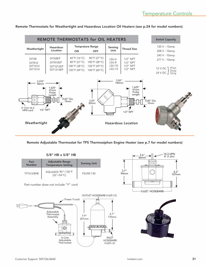
Remote Thermostats for Weathertight and Hazardous Location Oil Heaters (see p.24 for model numbers)
5/8” HB x 5/8” HB
Part Number
Adjustable Range Temperature Setting
Sensing Unit
TFTA-5/8HBAdjustable 90 °–130 °F
(32 °–54 °C)FSU90-130
0.625” HOSEBARB
4.2”107mm
3.7”94mm
2.6”66mm
14-3 HPN4’ (1.2m)
Remote Adjustable Thermostat for TPS Thermosiphon Engine Heater (see p.7 for model numbers)
In-LineAdjustableThermostat
6.7”170mm7.9”
201mm
OUTLET HOSEBARB 0.625 I.D.
INLETHOSEBARB0.625 I.D.
Power Y-cord
AdjustableThermostatAssembly
31Customer Support: 509.536.8660 hotstart.com
Temperature Controls
Weathertight Hazardous Location
Part number does not include “Y” cord
REMOTE THERMOSTATS for OIL HEATERS
Weathertight Hazardous Location
Temprature Range
ON OFFSensing
UnitThread Size
DIT68DIT810DIT1012DIT1214
DIT68EPDIT810EPDIT1012EPDIT1214EP
60 °F (16 °C) 80 °F (27 °C) 80 °F (27 °C) 100 °F (38 °C) 100 °F (38 °C) 120 °F (49 °C) 120 °F (49 °C) 140 °F (60 °C)
LSU-6LSU-8LSU-10LSU-12
1/2” NPT1/2” NPT1/2” NPT1/2” NPT
Switch Capacity
120 V - 15amp
208 V - 10amp
240 V - 10amp
277 V - 10amp
12 V DC
24 V DC
Pilot Duty Only}
3.375”86mm
1.625”41mmProbeLength
1/2” NPT
0.60” Dia.15mm
3’ (1m) 16-3HPN cord
5.50”140mm
1.625”41mmProbeLength
1/2” NPT
0.60” Dia.15mm
3.25”83mm

32 Customer Service: 509.536.8660 hotstart.com
3.6”92mm
1.8”46mm
4X 1/2”CONDUIT
KNOCKOUT
4.3”110mm
1”NPT(FEMALE) 1”NPT
(MALE)
4.8”122mm
3.6”92mm
1.8”46mm
4X 1/2”CONDUIT
KNOCKOUT
4.3”110mm
1”NPT(MALE) 1”NPT
(MALE)
5.0”127mm
3.6”92mm
1.8”46mm
4X 1/2”CONDUIT
KNOCKOUT
4.3”110mm
1”HB1”NPT(MALE)
5.0”127mm
3.0”76mm
1.25”32mm
1.0”
5.0”127mm
2.25”57mm
1" NPT Inlet
1/2" NPT Conduit Opening
1”NPT female x 1”NPT male
CONDUIT TYPE ENCLOSURE
Part Number
Temperature Setting
Maximum Capacity Ratings
On Off120/240V
277V 480V
TFTC8-200TFTC10-200TFTC12-200
80 °F (27 °C) 100 °F (38 °C)100 °F (38 °C) 120 °F (49 °C)120 °F (49 °C) 140 °F (60 °C)
25amp25amp25amp
22amp22amp22amp
12.5amp12.5amp12.5amp
TFTCA-200Adjustable 90 °–130 °F
(32 °–54 °C)25amp 22amp 12.5amp
1”NPT male x 1”NPT male
CONDUIT TYPE ENCLOSURE
Part Number
Temperature Setting
Maximum Capacity Ratings
On Off120/240V
277V 480V
TFTC8-220TFTC10-220TFTC12-220
80 °F (27 °C) 100 °F (38 °C)100 °F (38 °C) 120 °F (49 °C)120 °F (49 °C) 140 °F (60 °C)
25amp25amp25amp
22amp22amp22amp
12.5amp12.5amp12.5amp
TFTCA-220Adjustable 90 °–130 °F
(32 °–54 °C)25amp 22amp 12.5amp
1” hose barb x 1”NPT male
CONDUIT TYPE ENCLOSURE
Part Number
Temperature Setting
Maximum Capacity Ratings
On Off120/240V
277V 480V
TFTC8-240TFTC10-240TFTC12-240
80 °F (27 °C) 100 °F (38 °C)100 °F (38 °C) 120 °F (49 °C)120 °F (49 °C) 140 °F (60 °C)
25amp25amp25amp
22amp22amp22amp
12.5amp12.5amp12.5amp
TFTCA-240Adjustable 90 °–130 °F
(32 °–54 °C)25amp 22amp 12.5amp
HAZARDOUS LOCATIONCONDUIT TYPE ENCLOSURE
Part Number
Temperature Setting
Maximum Capacity Ratings
On Off120/240V
277V 480V
TFT10ER 100 °F (38 °C) 120 °F (49 °C) 25amp 22amp 12.5amp
When using a thermostat above rated capacity or on 3 phase applications, select the proper control box with transformer and contactor as shown on page 34.Temperature Controls

33Customer Service:
509.536.8660 hotstart.com
3.6”92mm
1.8”46mm
4X 1/2”CONDUIT
KNOCKOUT
5.4”137mm
1”NPT(FEMALE)
1”NPT(MALE)
4.8”122mm
3.6”92mm
1.8”46mm
4X 1/2”CONDUIT
KNOCKOUT
5.4”137mm
1”NPT(MALE)
1”NPT(MALE)
5.0”127mm
3.6”92mm
1.8”46mm
4X 1/2”CONDUIT
KNOCKOUT
5.4”137mm
1”HB1”NPT(MALE)
5.0”127mm
60 95
125
155
185
215250
LO
3.0”76mm1.9”
48mm
3.4”86mm
.078”2.0mm
Dia.
5.0”127mm
6.4”163mm
1”NPT female x 1”NPT male
CORD CONNECTED
Part Number
Temperature Setting
Maximum Capacity Ratings
On Off120/240V
277V
TFT8-200TFT10-200TFT12-200
80 °F (27 °C) 100 °F (38 °C)100 °F (38 °C) 120 °F (49 °C)120 °F (49 °C) 140 °F (60 °C)
15amp15amp15amp
15amp15amp15amp
TFTA-200Adjustable 90 °–130 °F
(32 °–54 °C)15amp 15amp
REMOTE ADJUSTABLEWith 5’ (1.5m) Capillary Probe
Part Number
Adjustable Range Temperature Setting
Maximum Capacity Ratings
120/208/240V
277V 480V
AT6525
65 - 250°F (18 - 121°C)(Open or Off Setting)
Differential 4°F (2.2°C)(Close or On Setting)
25amp 22amp 5amp
ATW Aluminum
Well for AT6525 1/2” NPT
Temperature Controls
1”NPT male x 1”NPT male
CORD CONNECTED
Part Number
Temperature Setting
Maximum Capacity Ratings
On Off120/240V
277V
TFT8-220TFT10-220TFT12-220
80 °F (27 °C) 100 °F (38 °C)100 °F (38 °C) 120 °F (49 °C)120 °F (49 °C) 140 °F (60 °C)
15amp15amp15amp
15amp15amp15amp
TFTA-220Adjustable 90 °–130 °F
(32 °–54 °C)15amp 15amp
1” hose barb x 1”NPT male
CORD CONNECTED
Part Number
Temperature Setting
Maximum Capacity Ratings
On Off120/240V
277V
TFT8-240TFT10-240TFT12-240
80 °F (27 °C) 100 °F (38 °C)100 °F (38 °C) 120 °F (49 °C)120 °F (49 °C) 140 °F (60 °C)
15amp15amp15amp
15amp15amp15amp
TFTA-240Adjustable 90 °–130 °F
(32 °–54 °C)15amp 15amp
When using a thermostat above rated capacity or on 3 phase applications, select the proper control box with transformer and contactor as shown on page 34.

34 Customer Service: 509.536.8660 hotstart.com
Control Systems
Model JBC14-100
See wiring schematic page 35
CONTROL SYSTEMS
CONTROL SYSTEMS featuring AUTOMATIC SHUTDOWN DEVICESWith 24 V DC Relay
Amps Volts1 Heater, 1 Thermostat
per application2 Heaters, 2 Thermostats
per application
30A Max30A Max30A Max30A Max30A Max30A Max
120208240400480575
JBC11-100JBC18-100JBC12-100JBC1A-100JBC14-100JBC15-100
JBC21-100JBC28-100JBC22-100JBC2A-100JBC24-100JBC25-100
All HOTSTART heaters with thermostat, operating on three phase current (at any voltage), require the use of a control system with a 3-pole contactor. All HOTSTART heaters with thermostat, operating over 480 V (single or three phase) require a control system to reduce the primary voltage to 120 V for the control circuit. For increased thermostat life, use a control system on all heaters above 277 V either single or three phase.
All control boxes can be used with either single or three phase heaters.Control boxes are available in Hazardous Location models - contact factory for part number.
For heater protection and power savings, HOTSTART recommends de-energizing the heater when engine is running. Control boxes are supplied with a 24 V relay to de-energize the heater upon engine start-up.
Control systems allow for quick electrical installation of all HOTSTART engine heaters. They are designed as a time and labor saving component. Control systems are especially useful on installations that require two coolant heaters or combinations of a coolant heater and oil heater/hydraulic heater etc.
All control boxes on this page are NEMA 4, 12 & IP66.
Model JBC24-100
See wiring schematic page 35

35Customer Service: 509.536.8660 hotstart.com
Control Systems
To control one 480 V heater at maximum 30 amps on manual start engine.
To control two 480 V heaters at maximum 30 amps on automatic start engines.
USER SUPPLIEDCIRCUIT BREAKER
CONTROLTRANSFORMER480V PRIMARY
MAINPOWER
IN
EQUIPMENT GROUNDMUST BE GROUNDED
USER SUPPLIED24VDCSIGNAL
USER SUPPLIEDTHERMOSTAT
A1
A2
K2 N/C
12
11
CB2
120V50VA
X1
H4 H1
X2
CB1
CONTACTORCOIL
K134 2
MAGNETICCONTACTORS
K1
L3
L2
L1
HEATINGELEMENT
Model JBC14-100
Model JBC24-100
USER SUPPLIEDCIRCUIT BREAKER
CONTROLTRANSFORMER480V PRIMARY
MAINPOWER
IN
EQUIPMENT GROUNDMUST BE GROUNDED
USER SUPPLIED24VDCSIGNAL
USER SUPPLIEDTHERMOSTAT
120V50VA
CONTACTORCOIL
MAGNETICCONTACTORS
HEATINGELEMENT
HEATINGELEMENT
A1
A2
K3 N/C12
11
CB4
X1
H4 H1
X2
CB1
K134
2
L3
L2
L1
35
K2 2
CONTACTORCOIL
CB2 CB3
K2K1
Wiring Schematic for JBC14-100
Wiring Schematic for JBC24-100
36 Customer Service: 509.536.8660 hotstart.com
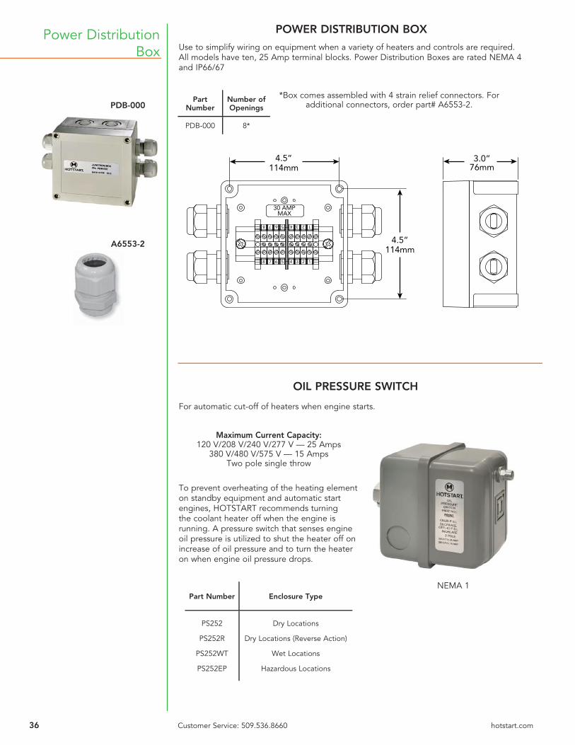
Power Distribution Box
PDB-000
A6553-2
4.5”114mm
4.5”114mm
3.0”76mm
30 AMPMAX
8 7 6 5 4 3 2 1
8 7 6 5 4 3 2 1
POWER DISTRIBUTION BOX
Use to simplify wiring on equipment when a variety of heaters and controls are required. All models have ten, 25 Amp terminal blocks. Power Distribution Boxes are rated NEMA 4 and IP66/67
Part Number
Number of Openings
PDB-000 8*
*Box comes assembled with 4 strain relief connectors. For additional connectors, order part# A6553-2.
Maximum Current Capacity:120 V/208 V/240 V/277 V — 25 Amps
380 V/480 V/575 V — 15 AmpsTwo pole single throw
To prevent overheating of the heating element on standby equipment and automatic start engines, HOTSTART recommends turning the coolant heater off when the engine is running. A pressure switch that senses engine oil pressure is utilized to shut the heater off on increase of oil pressure and to turn the heater on when engine oil pressure drops.
Part Number Enclosure Type
PS252
PS252R
PS252WT
PS252EP
Dry Locations
Dry Locations (Reverse Action)
Wet Locations
Hazardous Locations
OIL PRESSURE SWITCH
For automatic cut-off of heaters when engine starts.
NEMA 1

SECTION 4
BATTERY PADS/WRAPS

38 Customer Service: 509.536.8660 hotstart.com
Battery heater not recommended for nickel cadmium batteries. When batteries are placed in an insulated battery box, a thermostat is recommended to sense battery box temperature to prevent overheating the battery.
Battery Heating Pads
Accessories For Multiple Battery Heating
Typical Connection - 2 Batteries on Each Side of Vehicle
Standard Pad for Single Battery
Style A
6’ HPN1.8m
B
A
KB
7515
-D
KB
7515
-D
KB
7515
-D
KB
7515
-S
Left Side Battery Box Right Side Battery Box
BEC-6
BY-T68 BPC-61
Ground
2’ (0.7m)4’ (1.2m)6’ (1.8m)8’ (2.4m)
3’ (1m)6’ (1.8m)
16-3 HPN
13.2”335mm
13.5”343mm
12.0”305mmCORD
16-3 HPN
Model Number Volts Watts Amps
Nominal Dimensions BatterySize
Style
A B
KB5015KB5015-SKB5015-D
120120120
505050
.42
.42
.42
12.75” (324mm)12.75” (324mm)12.75” (324mm)
8.25” (210mm)8.25” (210mm)8.25” (210mm)
4D4D4D
ABC
KB7515KB7515-SKB7515-D
120120120
757575
.63
.63
.63
19.5” (495mm)19.5” (495mm)19.5” (495mm)
10.5” (267mm)10.5” (267mm)10.5” (267mm)
8D8D8D
ABC
KB7523KB7523-SKB7523-D
240240240
757575
.31
.31
.31
19.5” (495mm)19.5” (495mm)19.5” (495mm)
10.5” (267mm)10.5” (267mm)10.5” (267mm)
8D8D8D
ABC
EXTENSION CORDS
Part Number Length
BEC-2 2’ (0.7m)
BEC-4 4’ (1.2m)
BEC-6 6’ (1.8m)
BEC-8 8’ (2.4m)
POWER SUPPLY CORDS
Part Number Length Volts
BPC-31 3’ (1m) 120
BPC-32 3’ (1m) 240
BPC-61 6’ (1.8m) 120
BPC-62 6’ (1.8m) 240
THERMOSTAT & “Y” CORD ASSEMBLY
Part Number
Temperature Control
On Off
BY-T68 60°F (16°C) 80°F (27°C)
Style B
9.0”229mm
16-3 HPN
B
A
Style C 16-3 HPN B
A9.0”229mm
Special Pads for Multiple Batteries
39Customer Service: 509.536.8660 hotstart.com
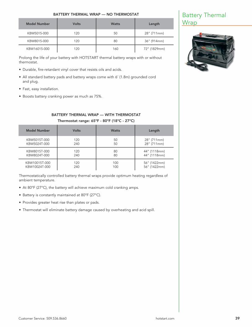
Battery Thermal Wrap
Prolong the life of your battery with HOTSTART thermal battery wraps with or without thermostat.
• Durable, fi re-retardant vinyl cover that resists oils and acids.
• All standard battery pads and battery wraps come with 6’ (1.8m) grounded cord and plug.
• Fast, easy installation.
• Boosts battery cranking power as much as 75%.
Thermostatically controlled battery thermal wraps provide optimum heating regardless of ambient temperature.
• At 80°F (27°C), the battery will achieve maximum cold cranking amps.
• Battery is constantly maintained at 80°F (27°C).
• Provides greater heat rise than plates or pads.
• Thermostat will eliminate battery damage caused by overheating and acid spill.
BATTERY THERMAL WRAP — NO THERMOSTAT
Model Number Volts Watts Length
KBW5015-000 120 50 28” (711mm)
KBW8015-000 120 80 36” (914mm)
KBW16015-000 120 160 72” (1829mm)
BATTERY THERMAL WRAP — WITH THERMOSTAT
Thermostat range: 65°F - 80°F (18°C - 27°C)
Model Number Volts Watts Length
KBW5015T-000KBW5024T-000
120240
5050
28” (711mm)28” (711mm)
KBW8015T-000KBW8024T-000
120240
8080
44” (1118mm)44” (1118mm)
KBW10015T-000KBW10024T-000
120240
100100
56” (1422mm)56” (1422mm)

40 Customer Service: 509.536.8660 hotstart.com
Silicone Pad HeatersVersatile and Easy to Install
HOTSTART adhesive pad heaters can be used on oil pans, hydraulic reservoirs, engine blocks, hydraulic cylinders and diesel fuel tanks.
• Easy peel and stick application.
• Etched foil heating element for optimal heat transfer and long life.
• Durable silicone/fi berglass cover resists abrasion.
• 120 V models are assembled with a standard 6’ (1.8m) HPN cord and plug. 240 V models include 6’ (1.8m) HPN cord without plug.
CAUTION: Do not use pads with higher than recommended wattage for specifi c oil capacities. For use on metal surfaces only.
Not for use on batteries
Model Number Volts Watts Dimensions
AF10015AF10024
120240
100100
4” x 5”(102mm x 127mm)
AF15015AF15024
120240
150150
4” x 5”(102mm x 127mm)
AF25015AF25024
120240
250250
5” x 6”(127mm x 152mm)
AF40015AF40024
120240
400400
6” x 8”(152mm x 203mm)
Application Guidline 100 Watt 150 Watt 250 Watt 400 Watt
Engine oil pan2 - 5 quarts1.9 - 4.7L
5 - 8 quarts4.7 - 7.5L
2 - 5 gallons7.5 - 19.0L
5 - 8 gallons19.0 - 30.3L
Diesel Tank5 - 7 gallons19.0 - 26.5L
7 - 10 gallons26.5 - 38.0L
10 - 20 gallons38.0 - 75.7L
20 - 30 gallons75.7 - 113.5L
Hydraulic Tank1 - 5 gallons4.0 - 19.0L
5 - 10 gallons19.0 - 38.0L
10 - 20 gallons38.0 - 75.7L
20 - 30 gallons75.7 - 113.5L
Water Tankup - 2 gallons
up - 7.5L2 - 4 gallons7.5 - 15.0L
4 - 7 gallons15.0 - 26.5L
7 - 10 gallons26.5 - 38.0L
41
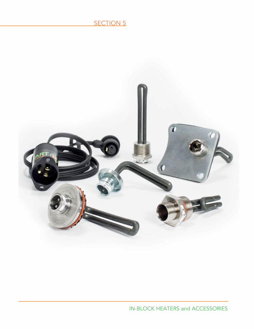
SECTION 5
IN-BLOCK HEATERS and ACCESSORIES
42 Customer Service: 509.536.8660 hotstart.com
C US
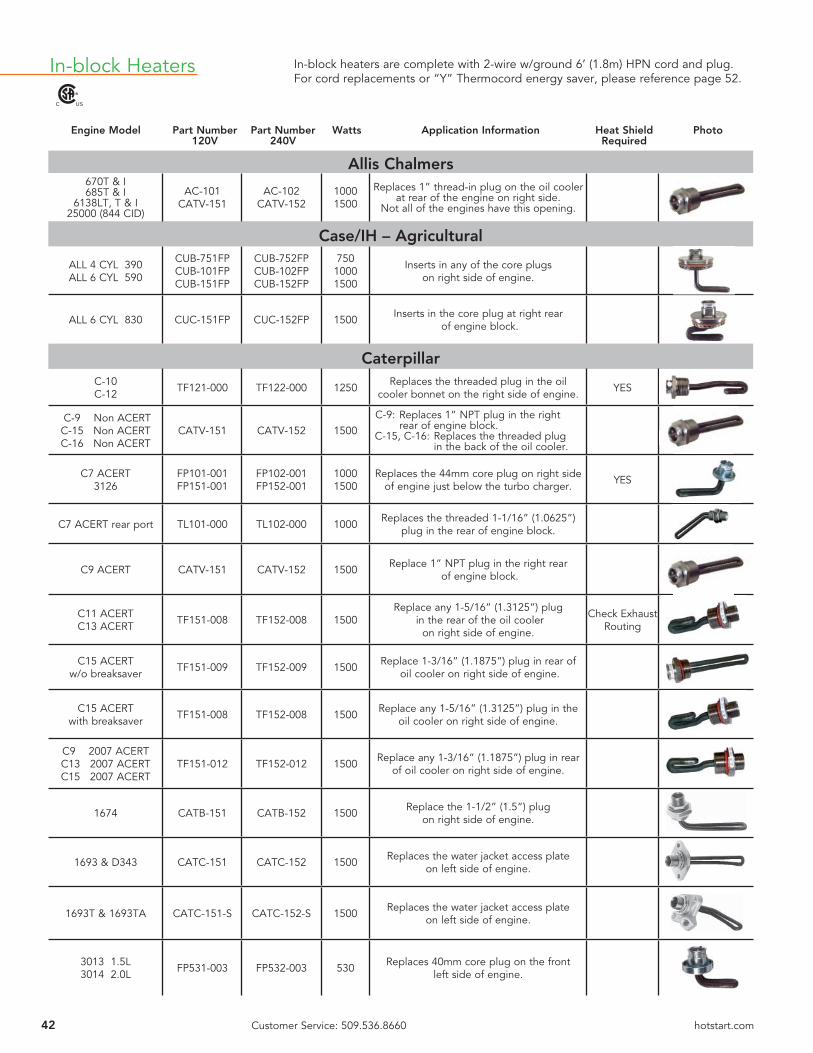
In-block Heaters In-block heaters are complete with 2-wire w/ground 6’ (1.8m) HPN cord and plug. For cord replacements or “Y” Thermocord energy saver, please reference page 52.
Engine Model Part Number Part Number Watts Application Information Heat Shield Photo 120V 240V Required
Allis Chalmers670T & I685T & I
6138LT, T & I25000 (844 CID)
AC-101CATV-151
AC-102CATV-152
10001500
Replaces 1” thread-in plug on the oil cooler at rear of the engine on right side.
Not all of the engines have this opening.
Case/IH – Agricultural
ALL 4 CYL 390ALL 6 CYL 590
CUB-751FPCUB-101FPCUB-151FP
CUB-752FPCUB-102FPCUB-152FP
75010001500
Inserts in any of the core plugs on right side of engine.
ALL 6 CYL 830 CUC-151FP CUC-152FP 1500 Inserts in the core plug at right rear of engine block.
CaterpillarC-10C-12 TF121-000 TF122-000 1250 Replaces the threaded plug in the oil
cooler bonnet on the right side of engine. YES
C-9 Non ACERTC-15 Non ACERTC-16 Non ACERT
CATV-151 CATV-152 1500C-9: Replaces 1” NPT plug in the right rear of engine block.C-15, C-16: Replaces the threaded plug in the back of the oil cooler.
C7 ACERT3126
FP101-001FP151-001
FP102-001FP152-001
10001500
Replaces the 44mm core plug on right side of engine just below the turbo charger. YES
C7 ACERT rear port TL101-000 TL102-000 1000 Replaces the threaded 1-1/16” (1.0625”) plug in the rear of engine block.
C9 ACERT CATV-151 CATV-152 1500 Replace 1” NPT plug in the right rear of engine block.
C11 ACERTC13 ACERT TF151-008 TF152-008 1500
Replace any 1-5/16” (1.3125”) plug in the rear of the oil cooler
on right side of engine.
Check Exhaust Routing
C15 ACERTw/o breaksaver TF151-009 TF152-009 1500 Replace 1-3/16” (1.1875”) plug in rear of
oil cooler on right side of engine.
C15 ACERTwith breaksaver TF151-008 TF152-008 1500 Replace any 1-5/16” (1.3125”) plug in the
oil cooler on right side of engine.
C9 2007 ACERTC13 2007 ACERTC15 2007 ACERT
TF151-012 TF152-012 1500 Replace any 1-3/16” (1.1875”) plug in rear of oil cooler on right side of engine.
1674 CATB-151 CATB-152 1500 Replace the 1-1/2” (1.5”) plug on right side of engine.
1693 & D343 CATC-151 CATC-152 1500 Replaces the water jacket access plate on left side of engine.
1693T & 1693TA CATC-151-S CATC-152-S 1500 Replaces the water jacket access plate on left side of engine.
3013 1.5L3014 2.0L FP531-003 FP532-003 530 Replaces 40mm core plug on the front
left side of engine.
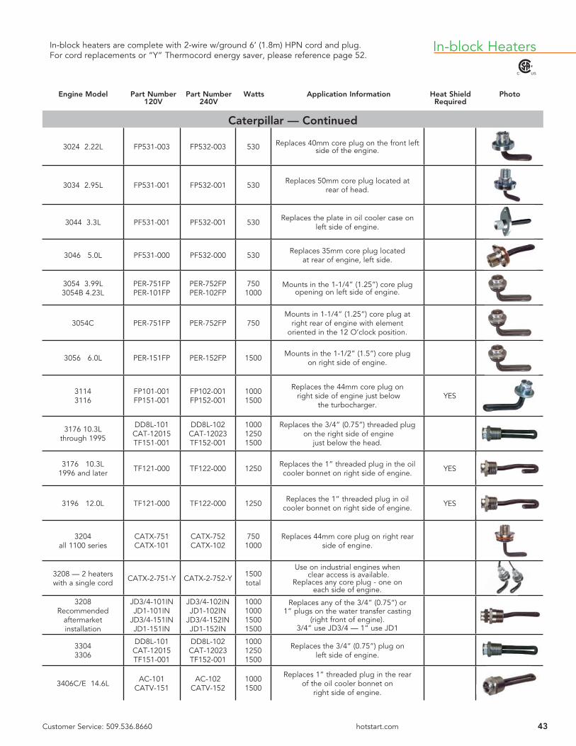
43Customer Service: 509.536.8660 hotstart.com
C US
In-block Heaters
Engine Model Part Number Part Number Watts Application Information Heat Shield Photo 120V 240V Required
Caterpillar — Continued
3024 2.22L FP531-003 FP532-003 530 Replaces 40mm core plug on the front left side of the engine.
3034 2.95L FP531-001 FP532-001 530 Replaces 50mm core plug located at rear of head.
3044 3.3L PF531-001 PF532-001 530 Replaces the plate in oil cooler case on left side of engine.
3046 5.0L PF531-000 PF532-000 530 Replaces 35mm core plug located at rear of engine, left side.
3054 3.99L3054B 4.23L
PER-751FPPER-101FP
PER-752FPPER-102FP
7501000
Mounts in the 1-1/4” (1.25”) core plug opening on left side of engine.
3054C PER-751FP PER-752FP 750Mounts in 1-1/4” (1.25”) core plug at
right rear of engine with element oriented in the 12 O’clock position.
3056 6.0L PER-151FP PER-152FP 1500 Mounts in the 1-1/2” (1.5”) core plug on right side of engine.
31143116
FP101-001FP151-001
FP102-001FP152-001
10001500
Replaces the 44mm core plug on right side of engine just below
the turbocharger.YES
3176 10.3Lthrough 1995
DD8L-101CAT-12015TF151-001
DD8L-102CAT-12023TF152-001
100012501500
Replaces the 3/4” (0.75”) threaded plug on the right side of engine
just below the head.
3176 10.3L1996 and later TF121-000 TF122-000 1250 Replaces the 1” threaded plug in the oil
cooler bonnet on right side of engine. YES
3196 12.0L TF121-000 TF122-000 1250 Replaces the 1” threaded plug in oil cooler bonnet on right side of engine. YES
3204all 1100 series
CATX-751CATX-101
CATX-752CATX-102
7501000
Replaces 44mm core plug on right rear side of engine.
3208 — 2 heaters with a single cord CATX-2-751-Y CATX-2-752-Y 1500
total
Use on industrial engines when clear access is available.
Replaces any core plug - one on each side of engine.
3208Recommended
aftermarket installation
JD3/4-101INJD1-101IN
JD3/4-151INJD1-151IN
JD3/4-102INJD1-102IN
JD3/4-152INJD1-152IN
1000100015001500
Replaces any of the 3/4” (0.75”) or 1” plugs on the water transfer casting
(right front of engine). 3/4” use JD3/4 — 1” use JD1
33043306
DD8L-101CAT-12015TF151-001
DD8L-102CAT-12023TF152-001
100012501500
Replaces the 3/4” (0.75”) plug on left side of engine.
3406C/E 14.6L AC-101CATV-151
AC-102CATV-152
10001500
Replaces 1” threaded plug in the rear of the oil cooler bonnet on
right side of engine.
In-block heaters are complete with 2-wire w/ground 6’ (1.8m) HPN cord and plug. For cord replacements or “Y” Thermocord energy saver, please reference page 52.

44 Customer Service: 509.536.8660 hotstart.com
C US
In-block Heaters In-block heaters are complete with 2-wire w/ground 6’ (1.8m) HPN cord and plug. For cord replacements or “Y” Thermocord energy saver, please reference page 52.
Engine Model Part Number Part Number Watts Application Information Heat Shield Photo 120V 240V Required
Caterpillar — Continued3406 & 3408except 1998
ADEM 2
AC-101CATV-151
AC-102CATV-152
10001500
Replaces 1” threaded plug in the rear of the oil cooler bonnet
on right side of engine.
3406E1998 ADEM 2engines only
TF151-002 TF152-002 1500Replaces the 1” threaded plug that points downward on the top of the rear of the oil
cooler bonnet.YES
3406E ADEM 3 and ADEM
2000 engines
AC-101CATV-151
AC-102CATV-152
10001500
Replaces 1” threaded plug in the rear of the oil cooler bonnet
on right side of engine.
3456 15.8L AC-101CATV-151
AC-102CATV-152
10001500
Replaces 1” threaded plug in the rear of the oil cooler bonnet
on right side of engine.
Cummins6 Cylinder Engines: H, NT, NH, N Family
743 CID, 855 CID, 927 CID, “N14”1. Cummins engines are often referred to by their horsepower rating “i.e. 350 Cummins”2. Cummins engines are often referred to as Big Cam, Big Cam2, 3, 4, full fl ow cooling, etc.All refer to engines of 855 CID Size – listed below
Group I
Flat plate design CUN-151B CUN-152B 1500
6 bolt fl at plate on the right side of the engine. May use either the forward or rear
opening depending on clearance.Flat plate design when the 1/2” NPT opening
is usedCUN-151BH CUN-152BH 1500
Group II
When an external oil cooler is used..
Note: When a 4 bolt fl at plate element design is encountered, remove the next two bolts on the casting, remove the whole casting, and replace the casting and element with either CNT-151B/CNT-152B OR CNT151B90/CNT152B90
When connection is 1 1/2” rubber hose
Engines produced Aug. 1975 thru June 1982
CNT-151B-90 CNT-152B-90 15006 bolt, fl at plate design with an elbow
that will rotate 360 degrees to connect with any hose or casting.
Uses an “O” ring forthe 1 1/4” water tube
connectionEngines produced prior
to August ‘75
CNT-151B CNT-152B 1500 6 bolt, fl at plate design with an elbow that will rotate 360 degrees to connect
with any hose or casting.
Group III
For industrial engines with hole pattern
reversedCUN-151BREV CUN-152BREV 1500 Six bolt fl at plate on the right side
of engine block.
Group IV
1998 and laterN14 Industrial PF151-002 PF152-002 1500 Six bolt fl at plate on the right side
of engine block.

45Customer Service: 509.536.8660 hotstart.com
C US
In-block heaters are complete with 2-wire w/ground 6’ (1.8m) HPN cord and plug. For cord replacements or “Y” Thermocord energy saver, please reference page 52.
In-block Heaters
Engine Model Part Number Part Number Watts Application Information Heat Shield Photo 120V 240V Required
Cummins — Continued
Cummins A4 cyl & 6 cyl CUA-101F CUA-102F 1000 Inserts in any of the core plugs on right
side of engine. Element points down.
ISC/QSC 8.3LISL/QSL 9.0L
DD8L-101TF751-002
DD8L-102TF752-002
1000750
Replaces 3/4” (0.75”) NPT plug in right front side of engine.
L10, M11ISM 2007 CUL-151 CUL-152 1500
Inserts in the forward opening of the heater casting on the right rear
of engine block.
QSB 3.9L, 5.9LISB 5.9 TF751-002 TF752-002 750 Replaces 3/4” (0.75”) NPT plug in the
front of the oil cooler casting.
ISM/QSM 11.0LFlat Plate Design PF151-003 PF152-003 1500 Right rear. Replaces plate.
ISX, QSXSignature 600
Pre 2007PF151-004 PF152-004 1500 Mounts in the oval shaped plate on the
right side of engine block.
4BT 3.9L CUB-751FPCUB-101FP
CUB-752FPCUB-102FP
7501000
Replaces 57.8mm core plug on right side of engine.
Check Exhaust Routing
6BT 5.9LCUB-751FPCUB-101FPCUB-151FP
CUB-752FPCUB-102FPCUB-152FP
75010001500
Replaces 57.8mm core plug on right side of engine.
Check Exhaust Routing
6CT 8.3L CUC-151FP CUC-152FP 1500 Replaces 57.8mm core plug on right rear side of engine.
Detroit Diesel
SERIES 104 cylinder
Phaser engines
PER-751FPPER-101FP
PER-752FPPER-102FP
7501000
Mounts in the 1-1/4” (1.25”) core plug opening on either side of engine.
SERIES 10 6 cylinder
Phaser enginesPER-151FP PER-152FP 1500 Mounts in the 1-1/4” (1.25”) core plug
on right side of engine.
SERIES 30 DD8L-101TF751-002
DD8L-102TF752-002
1000750
Mounts in the 3/4” (0.75”) NPT opening in engine block.
SERIES 40all versions
PER-751FPINTA-121FR151-001
PER-752FPINTA-122FR152-001
75012501500
Mounts in the core plug opening on right side of engine.
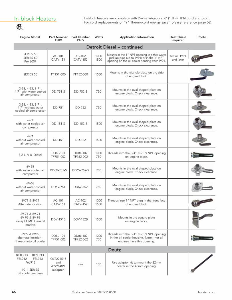
46 Customer Service: 509.536.8660 hotstart.com
C US
In-block Heaters In-block heaters are complete with 2-wire w/ground 6’ (1.8m) HPN cord and plug. For cord replacements or “Y” Thermocord energy saver, please reference page 52.
Engine Model Part Number Part Number Watts Application Information Heat Shield Photo 120V 240V Required
Detroit Diesel – continuedSERIES 50SERIES 60Pre 2007
AC-101CATV-151
AC-102CATV-152
10001500
Mounts in the 1” NPT opening in either water pick up pipe (up to 1991) or in the 1” NPT
opening on the oil cooler housing after 1991.
Yes on 1991 and later
SERIES 55 PF151-000 PF152-000 1500 Mounts in the triangle plate on the sideof engine block.
3-53, 4-53, 3-71, 4-71 with water cooled
air compressorDD-751-S DD-752-S 750 Mounts in the oval shaped plate on
engine block. Check clearance.
3-53, 4-53, 3-71, 4-71 without water
cooled air compressorDD-751 DD-752 750 Mounts in the oval shaped plate on
engine block. Check clearance.
6-71with water cooled air
compressorDD-151-S DD-152-S 1500 Mounts in the oval shaped plate on
engine block. Check clearance.
6-71 without water cooled
air compressorDD-151 DD-152 1500 Mounts in the oval shaped plate on
engine block. Check clearance.
8.2 L V-8 Diesel DD8L-101TF751-002
DD8L-102TF752-002
1000750
Threads into the 3/4” (0.75”) NPT openingon engine block.
6V-53with water cooled air
compressorDD6V-751-S DD6V-752-S 750 Mounts in the oval shaped plate on
engine block. Check clearance.
6V-53without water cooled
air compressorDD6V-751 DD6V-752 750 Mounts in the oval shaped plate on
engine block. Check clearance.
6V71 & 8V71Alternate location
AC-101CATV-151
AC-102CATV-152
10001500
Threads into 1” NPT plug in the front face of engine block.
6V-71 & 8V-716V-92 & 8V-92
except GMC General models
DDV-151B DDV-152B 1500 Mounts in the square plate on engine block.
6V92 & 8V92alternate location -
threads into oil cooler
DD8L-101TF751-002
DD8L-102TF752-002
1000750
Threads into the 3/4” (0.75”) NPT opening in the oil cooler housing. Note - not all
engines have this opening.
Deutz BF4L913 BF6L913 F3L912 F3L913
F6L913
1011 SERIESoil cooled engines
OLT221515 and
A22M48M (adapter)
n/a 150 Use adapter kit to mount the 22mm heater in the 48mm opening.

47Customer Service: 509.536.8660 hotstart.com
C US
In-block heaters are complete with 2-wire w/ground 6’ (1.8m) HPN cord and plug. For cord replacements or “Y” Thermocord energy saver, please reference page 52.
In-block Heaters
Engine Model Part Number Part Number Watts Application Information Heat Shield Photo 120V 240V Required
Deutz – continued
1012 — 4 & 6 cyl1013 — 4 cyl
PF751-000PF121-001
PF752-000PF122-001
7501250
Mounts in the oval shaped plate opening on the oil cooler casting.
1013 6 cyl PF121-001PF751-000
PF122-001PF752-000
1250750
Mounts in the oval shaped plate opening on the top of the oil cooler.
10156 & 8 cyl TL151-004 TL152-004 1500 Replaces 30mm plug in water elbow
on front of engine.
2012 — 4 & 6 cylwithout electric fuel injection
PF751-002 PF752-002 750 Replace oval shaped plate on the top of the oil cooler.
Ford
7.3L V-8 dieselsfrom 1994 on
TF751-002 DD8L-101
TF752-002 DD8L-102
7501000
Mounts in the 3/4” (0.75”) NPT plug in the engine’s block.
Hino
3.8L, 5.8L, 6.0L, 6.4L, 6.7L, H06C-T, H07C-B,
W04C-T, W06E
DD8L-101TF751-002
DD8L-102TF752-002
1000750
Threads into 3/4” (0.75”) NPT opening in engine block. YES
Isuzu
4BD1 6HE1 6BD1 6SA1 6BG1
TF401-001 NONE 400 Replaces 1” NPT plug on left rear of engine.
Iveco
NEF 4cylNEF 6 cyl PF751-001 PF752-001 750 Mount in front opening on right side
of engine block.
John Deere
With 3/4” plug in the back of the block
JD3/4-101INJD3/4-151IN
JD3/4-102INJD3/4-152IN
10001500
3/4” (0.75”) NPT opening in the rear face of engine block.
CheckExhaust Routing
With 1” plug in the back of the block
JD1-101INJD1-151IN
JD1-102INJD1-152IN
10001500
1” NPT opening in the rear face of engine block.
With 1-5/8” opening on the side of the
water jacket
JDS-101JDS-151
JDS-102JDS-152
10001500
1-5/8” (1.625”) threaded opening on the side of the block in the water
distribution channel.
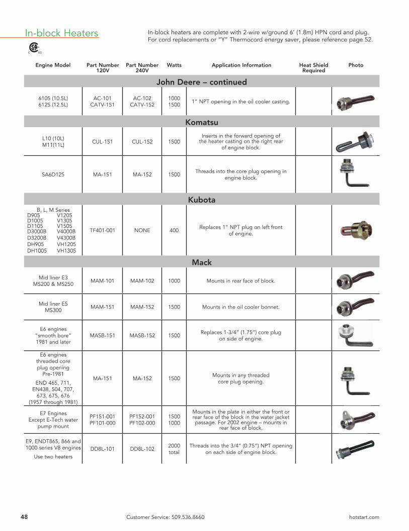
48 Customer Service: 509.536.8660 hotstart.com
C US
In-block Heaters In-block heaters are complete with 2-wire w/ground 6’ (1.8m) HPN cord and plug. For cord replacements or “Y” Thermocord energy saver, please reference page 52.
Engine Model Part Number Part Number Watts Application Information Heat Shield Photo 120V 240V Required
John Deere – continued
6105 (10.5L)6125 (12.5L)
AC-101CATV-151
AC-102CATV-152
10001500 1” NPT opening in the oil cooler casting.
Komatsu
L10 (10L)M11(11L) CUL-151 CUL-152 1500
Inserts in the forward opening of the heater casting on the right rear
of engine block.
SA6D125 MA-151 MA-152 1500 Threads into the core plug opening inengine block.
KubotaB, L, M Series
D905 V1205D1005 V1305D1105 V1505D3000B V4000BD3200B V4300BDH905 VH1205DH1005 VH1305
TF401-001 NONE 400 Replaces 1” NPT plug on left front of engine.
Mack
Mid liner E3MS200 & MS250 MAM-101 MAM-102 1000 Mounts in rear face of block.
Mid liner E5MS300 MAM-151 MAM-152 1500 Mounts in the oil cooler bonnet.
E6 engines“smooth bore”1981 and later
MASB-151 MASB-152 1500 Replaces 1-3/4” (1.75”) core plug on side of engine.
E6 enginesthreaded coreplug opening
Pre-1981
END 465, 711,EN438, 504, 707,
673, 675, 676(1957 through 1981)
MA-151 MA-152 1500 Mounts in any threaded core plug opening.
E7 EnginesExcept E-Tech water
pump mount
PF151-001PF101-000
PF152-001PF102-000
15001000
Mounts in the plate in either the front or rear face of the block in the water jacket passage. For 2002 engine – mounts in
rear face of block.
E9, ENDT865, 866 and 1000 series V8 engines
Use two heatersDD8L-101 DD8L-102 2000
totalThreads into the 3/4” (0.75”) NPT opening
on each side of engine block.

49Customer Service: 509.536.8660 hotstart.com
C US
In-block heaters are complete with 2-wire w/ground 6’ (1.8m) HPN cord and plug. For cord replacements or “Y” Thermocord energy saver, please reference page 52.
In-block Heaters
Engine Model Part Number Part Number Watts Application Information Heat Shield Photo 120V 240V Required
MAN
D2840D2842D2848
PF121-003 PF122-003 1250 Replace oval shaped plate in lower water pipe on right side of engine.
D2866D2876 PF151-006 PF152-006 1500
Replace 3 bolt plate on left side of engine. May require adapter if 3 bolt opening
is not available on engine.Consult customer service.
Massey Ferguson3 cylinder4 cylinder6 cylinder
PER-751FPPER-101FP
PER-752FPPER-102FP
7501000
Mounts in any of the 1-1/4” (1.25”) core plug openings in the engine. YES
Mercedes BenzMBE904MBE906MBE924MBE925
PF101-001 PF102-001 1000 Replaces 60mm core plug on right rear of engine.
Navistar/International
V800 (796 CID) AC-101CATV-151
AC-102CATV-152
10001500
Threads into a 1” NPT opening in the oil cooler bonnet.
INLINE 6 CYLINDER— all series —
312, 360, 414, 436,466 & 530
INTA-121INTA-101
INTA-122INTA-102
12501000
Replaces third or fourth core plug on left side of engine. Element should point
toward 1 O’clock position.
7.3L & T4441994 and later
TF751-002DD8L-101
TF752-002DD8L-102
7501000
Mounts in the 3/4” (0.75”) NPT plug in the engine’s block.
9.0L — V8 diesel INT9-101F INT9-102F 1000 Mounts in a core plug.
Oliver
ALL EXCEPT 1265, 1365 & 1900
TF751-002DD8L-101
TF752-002DD8L-102
7501000
Threads into a 3/4” (0.75”) NPT opening in the block.
Onan — See Cummins “A” Series
Perkins3.1524.2366.354
PER-751FPPER-101FP
PER-752FPPER-102FP
7501000
Mounts in the 1-1/4” (1.25”) core plug opening on right side of engine.
103.15104.22404.22
FP531-003 FP532-003 530 Replaces core plug on left front of engine.

50 Customer Service: 509.536.8660 hotstart.com
C US
In-block Heaters In-block heaters are complete with 2-wire w/ground 6’ (1.8m) HPN cord and plug. For cord replacements or “Y” Thermocord energy saver, please reference page 52.
NOTE: The only replacement part for in-block heaters is the power cord. Please see the power cord section on page 52 for the proper replacement cord set.
For thermostat control of in-block heaters, see page 52. The energy saver Thermocord is available in various temperature ranges.
Supplemental heat for engines using in-block heaters can be achieved by the installation of lube-oil heaters in the oil pan. Reference pages 24 and 25 of this catalog or consult factory.
Engine Model Part Number Part Number Watts Application Information Heat Shield Photo 120V 240V Required
Perkins – continued
700 Series704.30 FP531-001 FP532-001 530 Replaces 50mm core plug located at
rear of head.
800 Series PF531-001 PF532-001 530 Mounts in oval shaped plate on the left front of the block.
1004 (right side)FR751-002FR101-000PER-151FP
FR752-002FR102-000PER-152FP
75010001500
Mounts in the 1-1/2” (1.5”) core plug opening on right side of engine.
1004 (left side) PER-751FPPER-101FP
PER-752FPPER-102FP
7501000
Mounts in the 1-1/4” (1.25”) core plug opening on left side of engine.
1006 (6 Cyl) A & B PER-151FP PER-152FP 1500 Mounts in the 1-1/2” (1.5”) core plug on right side of engine.
1103C FR531-000-WOC
FR532-000-WOC 530
Replaces 1-1/4” (1.25”) core plug onright rear of engine. Element should point
towards 1 O’clock position.
1104 (4 Cyl) C & D PER-751FPPER-101FP
PER-752FPPER-102FP
7501000
Mounts in 1-1/4” (1.25”) core plug opening on right side of engine.
Volvo
D9 PF151-007 PF152-007 1500 Replaces oval shaped plate onright side of engine.
D12CPrior to Serial #250502 PF151-005 PF152-005 1500 Replaces oval shaped plate on
right side of engine. YES
D12CAfter Serial #250502 PF121-002 PF122-002 1250 Replaces oval shaped plate on
right side of engine. YES
TD60, TD61, TD70, TD71, TD100, TD101, VE10, TD120, TD121
VT6-101 VT6-102 1000 Mounts into threaded opening onleft side of engine.
Yanmar 3T72HLE4TN82E
D4TYYDXL4.41
TF401-001 NONE 400 1” NPTNo replacement cord available.
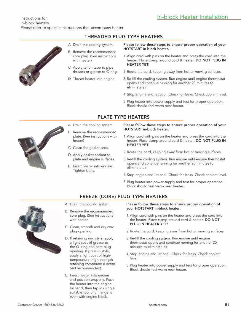
51Customer Service: 509.536.8660 hotstart.com
THREADED PLUG TYPE HEATERS
PLATE TYPE HEATERS
FREEZE (CORE) PLUG TYPE HEATERS
Please follow these steps to ensure proper operation of your HOTSTART in-block heater.
1. Align cord with pins on the heater and press the cord into the heater. Place clamp around cord & heater. DO NOT PLUG IN HEATER YET!
2. Route the cord, keeping away from hot or moving surfaces.
3. Re-fi ll the cooling system. Run engine until engine thermostat opens and continue running for another 20 minutes to eliminate air.
4. Stop engine and let cool. Check for leaks. Check coolant level.
5. Plug heater into power supply and test for proper operation. Block should feel warm near heater.
A. Drain the cooling system.
B. Remove the recommended core plug. (See instructions with heater)
C. Apply tefl on tape to pipe threads or grease to O-ring.
D. Thread heater into engine.
A. Drain the cooling system.
B. Remove the recommended plate. (See instructions with heater)
C. Clean the gasket area.
D. Apply gasket sealant to plate and engine surfaces.
E. Insert heater into engine. Tighten bolts.
Please follow these steps to ensure proper operation of your HOTSTART in-block heater.
1. Align cord with pins on the heater and press the cord into the heater. Place clamp around cord & heater. DO NOT PLUG IN HEATER YET!
2. Route the cord, keeping away from hot or moving surfaces.
3. Re-fi ll the cooling system. Run engine until engine thermostat opens and continue running for another 20 minutes to eliminate air.
4. Stop engine and let cool. Check for leaks. Check coolant level.
5. Plug heater into power supply and test for proper operation. Block should feel warm near heater.
A. Drain the cooling system.
B. Remove the recommended core plug. (See instructions with heater)
C. Clean, smooth and dry core plug opening.
D. If retaining ring style, apply a light coat of grease to the O- ring and core plug opening. If press-in style, apply a light coat of high-temperature, high-strength retaining compound (Loctite 640 recommended).
E. Insert heater into engine and position properly. Push the heater into the engine by hand, then tap in using a suitable tool until fl ange is even with engine block.
Please follow these steps to ensure proper operation of your HOTSTART in-block heater.
1. Align cord with pins on the heater and press the cord into the heater. Place clamp around cord & heater. DO NOT PLUG IN HEATER YET!
2. Route the cord, keeping away from hot or moving surfaces.
3. Re-fi ll the cooling system. Run engine until engine thermostat opens and continue running for another 20 minutes to eliminate air.
4. Stop engine and let cool. Check for leaks. Check coolant level.
5. Plug heater into power supply and test for proper operation. Block should feel warm near heater.
Instructions for:In-block heatersPlease refer to specifi c instructions that accompany heater.
In-block Heater Installation

52 Customer Service: 509.536.8660 hotstart.com
Replacement Cords & Thermostats
Thermocord for In-block Heaters
Part No. VoltsThread
SizeTemp Range
TC031310-866 120 1/2” 100 °–120 °F (38 °– 49 °C)
TC031312-866 120 1/2” 120 °–140 °F (49 °– 60 °C)
TC032310-866 240 1/2” 100 °–120 °F (38 °– 49 °C)
TC032312-866 240 1/2” 120 °–140 °F (49 °– 60 °C)
TC031308-866 120 1/2” 80 °–100 °F (27 °– 38 °C)
TC032308-866 240 1/2” 80 °–100 °F (27 °– 38 °C)
4’1.2m
3 ft.1m
NOTE: When ordering in-block
heater and thermocord, place
suffi x –WOC (which stands
for without cord) after the
heater model number to save
cost as the standard 6’ (1.8m)
heater cord is replaced by the
Thermocord harness.
Heater shown for illustration purposes only
Heat Shield
HS1
Use when exhaust manifold or turbo come close to heater termination.
For use with In-block Heaters
Cord Length
PlugStyle
120 Volt 240 Volt
6’1.8m 1 IM6-1IN IM6-2IN
11’3.4m 1 IM11-1IN IM11-2IN
16’4.8m 1 IM16-1IN IM16-2IN
Cord Length
PlugStyle
120 Volt 240 Volt
6’1.8m 2 11PR72T 21PR72T
11’3.4m 2 11PR132T 21PR132T
16’4.8m 2 11PR192T 21PR192T
STYLE 1
STYLE 2
C US
C US
11PR72T
IM6-1IN
Fits most competitor’s applications.
15amp, 120V
15amp, 240V
15amp, 120V
15amp, 240V
C US
3 ft.1m
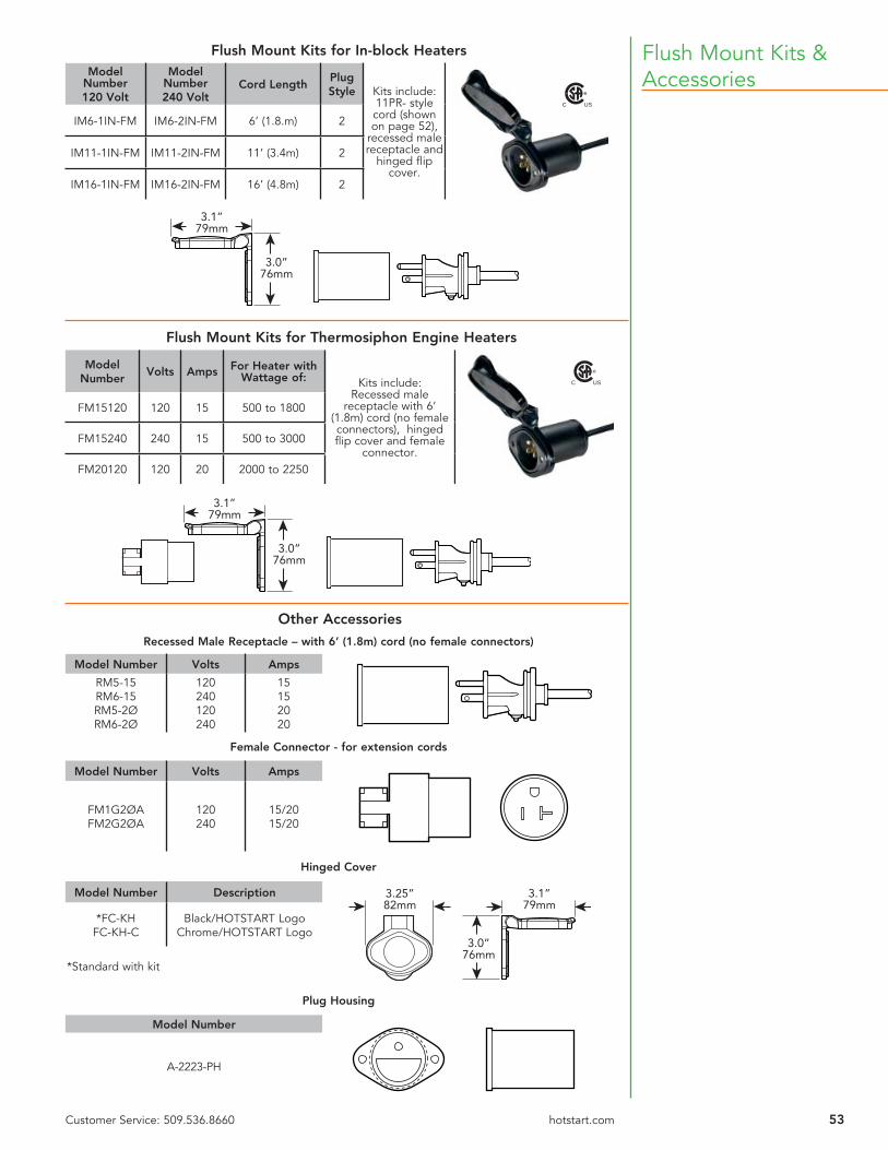
53Customer Service: 509.536.8660 hotstart.com
Flush Mount Kits & Accessories
Other Accessories
Flush Mount Kits for Thermosiphon Engine Heaters
Model Number
Volts Amps For Heater with Wattage of: Kits include:
Recessed male receptacle with 6’
(1.8m) cord (no female connectors), hinged fl ip cover and female
connector.
FM15120 120 15 500 to 1800
FM15240 240 15 500 to 3000
FM20120 120 20 2000 to 2250
3.1”79mm
3.0”76mm
Recessed Male Receptacle – with 6’ (1.8m) cord (no female connectors)
Model Number Volts Amps
RM5-15RM6-15RM5-2ØRM6-2Ø
120240120240
15152020
Female Connector - for extension cords
Model Number Volts Amps
FM1G2ØAFM2G2ØA
120240
15/2015/20
Hinged Cover
Model Number Description 3.1”79mm
3.0”76mm
3.25”82mm
*FC-KHFC-KH-C
Black/HOTSTART LogoChrome/HOTSTART Logo
*Standard with kit
Plug Housing
Model Number
A-2223-PH
Flush Mount Kits for In-block HeatersModel
Number120 Volt
Model Number240 Volt
Cord LengthPlug Style Kits include:
11PR- style cord (shown on page 52),
recessed male receptacle and
hinged fl ip cover.
IM6-1IN-FM IM6-2IN-FM 6’ (1.8.m) 2
IM11-1IN-FM IM11-2IN-FM 11’ (3.4m) 2
IM16-1IN-FM IM16-2IN-FM 16’ (4.8m) 2
3.1”79mm
3.0”76mm
C US
C US

54 Customer Service: 509.536.8660 hotstart.com
Specifying an Engine Heater
Cubic Inches x 0.01639 = LitersLiters x 61.024 = Cubic Inches
Temperature
C x 1.8 + 32 = °F(F - 32) x 0.55 = °C
Cubic Inches - Litres Conversion Chart
1. Determine the best type of heater to be used for the application.• In-block or Thermosiphon Engine Heater?• Weathertight model for all indoor or outdoor applications (hospital, communications
building, shopping mall, pump station, off-road equipment).• Hazardous Location model (off-shore platform, oil rig, gas compression station).
2. Determine engine size.• Cubic inch or liter displacement.
3. Determine wattage required by using this general formula:• 3 watts x cubic inch displacement = watts required.
Example: Engine is 855 CID. Requirement is 2500 watt heater. (855 x 3 = 2565) • This formula is a very good rule of thumb to use down to 0 °F (-18 °C) ambient
temperature. This formula will generally hold engine temperature at approximately 100 °F (38 °C) above ambient.
• Engines over 1250 CID (20 L) and V-type engines require forced circulation preheating systems (CTM, CSM models — see pages 4-5).
4. Now that you have the required wattage, you need to determine:• Voltage available that will power the heater (120, 208, 277, 240, 380, 480).• Is the power source Single Phase or Three Phase?
5. For thermostat selection, determine the desired engine temperature to be maintained.• 100 °F (38 °C) to 120 °F (49 °C) applies 95% of the time. However, specifi cations vary with
respect to the user and a higher or lower range may be required.
You now have the specifi cations needed to select the required engine preheater from the many products listed in this catalog. For other technical information and installation tips, see pages 22 and 51. If you have other questions or need additional assistance, please contact our customer service department.
Conversion Factors
Litres x 1.0567 = QuartsQuarts x 0.94635 = LitresLitres x 0.26417 = GallonsGallons x 3.7854 = Litres
Cubic Inches Litres Cubic Inches Litres Cubic Inches Litres
150 2.46 1600 26.22 3050 49.98200 3.28 1650 27.04 3100 50.80250 4.10 1700 27.86 3150 51.62300 4.92 1750 28.68 3200 52.44350 5.74 1800 29.50 3250 53.26400 6.55 1850 30.32 3300 54.08450 7.37 1900 31.13 3350 54.90500 8.19 1950 31.95 3400 55.71550 9.01 2000 32.77 3450 56.53600 9.83 2050 33.59 3500 57.35650 10.65 2100 34.41 3550 58.17700 11.47 2150 35.23 3600 58.99750 12.29 2200 36.05 3650 59.81800 13.11 2250 36.87 3700 60.63850 13.93 2300 37.69 3750 61.45900 14.75 2350 38.51 3800 62.27950 15.57 2400 39.33 3850 63.091000 16.39 2450 40.15 3900 63.911050 17.21 2500 40.97 3950 64.731100 18.03 2550 41.79 4000 65.551150 18.84 2600 42.61 4050 66.371200 19.66 2650 43.42 4100 67.191250 20.48 2700 44.24 4150 68.001300 21.30 2750 45.06 4200 68.821350 22.12 2800 45.88 4250 69.641400 22.94 2850 46.70 4300 70.461450 23.76 2900 47.52 4350 71.281500 24.58 2950 48.34 4400 72.101550 25.40 3000 49.16 4450 72.92
Fahrenheit Celsius
-40 °F -40 °C-30 °F -34 °C-20 °F -29 °C-10 °F -23 °C0 °F -18 °C10 °F -12 °C20 °F - 7 °C30 °F - 1 °C40 °F 4.5 °C50 °F 10.0 °C60 °F 15.5 °C70 °F 21.0 °C80 °F 27.0 °C90 °F 32.0 °C100 °F 38.0 °C110 °F 43.0 °C120 °F 49.0 °C130 °F 54.0 °C140 °F 60.0 °C150 °F 65.5 °C160 °F 71.0 °C170 °F 77.0 °C180 °F 82.0 °C190 °F 88.0 °C200 °F 93.0 °C210 °F 99.0 °C
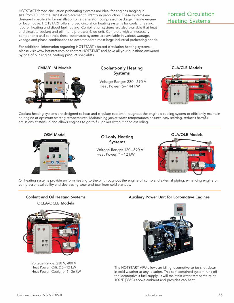
55Customer Service: 509.536.8660 hotstart.com
HOTSTART forced circulation preheating systems are ideal for engines ranging in size from 10 L to the largest displacement currently in production. These systems are designed specifi cally for installation on a generator, compressor package, marine engine or locomotive. HOTSTART offers forced circulation heating systems for coolant heating, lube oil heating and diesel fuel heating. Combination systems are also available that heat and circulate coolant and oil in one pre-assembled unit. Complete with all necessary components and controls, these automated systems are available in various wattage, voltage and phase combinations to accommodate most large industrial preheating needs.
For additional information regarding HOTSTART’s forced circulation heating systems, please visit www.hotstart.com or contact HOTSTART and have all your questions answered by one of our engine heating product specialists.
CMM/CLM Models
Forced Circulation Heating Systems
Voltage Range: 230 – 690 VHeat Power: 6 – 144 kW
CLA/CLE Models
OSM Model OLA/OLE Models
Voltage Range: 120 – 690 VHeat Power: 1 – 12 kW
Coolant heating systems are designed to heat and circulate coolant throughout the engine’s cooling system to effi ciently maintain an engine at optimum starting temperatures. Maintaining jacket water temperatures ensures easy starting, reduces harmful emissions at start-up and allows engines to go to full power without needless idling.
Oil heating systems provide uniform heating to the oil throughout the engine oil sump and external piping, enhancing engine or compressor availability and decreasing wear and tear from cold startups.
Coolant-only Heating Systems
Oil-only Heating Systems
Voltage Range: 230 V, 400 VHeat Power (Oil): 2.5 – 12 kWHeat Power (Coolant): 6 – 36 kW
Coolant and Oil Heating Systems
OCLA/OCLE Models
Auxiliary Power Unit for Locomotive Engines
The HOTSTART APU allows an idling locomotive to be shut down in cold weather at any location. This self-contained system runs off the locomotive’s fuel supply. It will maintain water temperature at 100 °F (38 °C) above ambient and provides cab heat.

56
Customer ServicesTo better serve you, HOTSTART provides a customer service department to answer all your engine heating concerns and questions or to take your sales order.
Customer Service Department: 509.536.8660
Sales orders and requests for quotes can also be faxed to our toll-freeFAX line.
Toll-free FAX line: 800.224.5550
Warranty InformationThe warranty below has been drafted to comply with the Federal Law applicable to products manufactured after December 31, 1976. This warranty gives you specifi c legal rights, and you may also have other rights which vary from state to state.
HOTSTART products are warranted against defects in workmanship and materials. No other express warranty, written or oral, applies. No person is authorized to give any other warranty or assume any liability except by written statement from an offi cer of HOTSTART, Inc.
The warranty extends for twelve months from date of shipment from factory or authorized distributor.
Products must be installed and maintained in accordance with HOTSTART, Inc. instructions. Users are responsible for the suitability of the products to their application. There is no warranty against damage resulting from corrosion, misapplication, improper specifi cation or other operating conditions beyond our control. Claims against carriers for damage in transit must be fi led by the buyer.
Absolutely no material can be returned to HOTSTART, Inc. without prior factory authorization.
Upon factory authorization, return the defective part or product, freight prepaid, to: HOTSTART, 5723 E Alki Ave, Spokane, WA 99212.
Defective items will be repaired or replaced, at our option, at no charge. Such repair or replacements is the exclusive right of HOTSTART, Inc. HOTSTART, Inc. is not liable for labor costs incurred in removal, reinstallation, or unauthorized repair of the product or for damage of any type whatsoever including incidental or consequential damage. Some states do not allow the exclusion or limitation of incidental or consequential damages, so the preceding limitation or exclusion may not apply to you.
Exports, re-exports and imports of HOTSTART products are subject to U.S. export controls. If you are an exporter, importer, distributor, customer or end-user, you are responsible for complying with U.S. export controls and any local export laws in your jurisdiction. We encourage you to seek appropriate legal advice before you export, re-export or sell HOTSTART products.
For more information on exporting products under the U.S. Export Administration Regulations (EAR), please visit the Bureau of Industry and Security (BIS) website: http://www.bis.doc.gov
HOTSTART, Inc.
www.hotstart.com
Distributor
10-16
Corporate and Manufacturing Headquarters5723 E Alki AveSpokane, WA [email protected]
Oil & Gas Offi ce21732 Provincial BlvdSuite 170Katy, TX [email protected]
Europe Offi ceHOTSTART GmbHAm Turm 8653721 [email protected]
Asia Pacifi c Offi ceHOTSTART Asia Pacifi c Ltd2-27-15-4F, HonkomagomeBunkyo-ku, Tokyo113-0021, [email protected]